Article

A Smart Sensors-Based Solar-Powered System to Monitor and Control Tube Well for Agriculture Applications

1
US Pakistan Center for Advance Studies in Energy, University of Engineering and Technology, Peshawar 25000, Pakistan
2
Department of Electrical Engineering, University of Engineering and Technology, Mardan 23200, Pakistan
3
Computer Sciences Program, Turabah University College, Taif University, P.O. Box 11099, Taif 21944, Saudi Arabia
4
Department of Electrical Engineering, Lahore College for Women University, Lahore 54000, Pakistan
5
Department of Electrical Engineering, University of Engineering and Technology, Peshawar 25000, Pakistan
6
Center of Excellence in Information Assurance, King Saud University, Riyadh 11653, Saudi Arabia
7
Department of Electrical Engineering, CECOS University of IT Emerging Sciences, Hayatabad, Peshawar 25100, Pakistan
*
Author to whom correspondence should be addressed.
Processes 2022, 10(8), 1654; https://doi.org/10.3390/pr10081654
Submission received: 21 July 2022 / Revised: 5 August 2022 / Accepted: 9 August 2022 / Published: 20 August 2022
(This article belongs to the Special Issue Advanced Processes Creating New Technologies in Tomorrow's Industry)

Abstract

:
Agricultural productivity plays a vital role in a country’s economy, which can be increased by providing the proper water needed for crops. Proper water provision ensures suitable moisture and appropriate conditions essential for crops, water resource preservation, minimized water wastage, and energy consumption. However, adequate water provision is challenging due to intermittent and uncertain environmental and weather conditions. On this note, a model with uncertain and stochastic conditions (rain, wet, dry, humidity, and moisture) capturing abilities is needed. Thus, a smart-sensors-based solar-powered system is developed for monitoring and controlling the tube well that ensures proper water provision to crops. The developed system properly checks weather and environmental conditions (rain, temperature, irradiance, humidity, etc.), soil conditions (wet or dry), and crop conditions to monitor and regulate water flow accordingly to minimize water and energy consumption wastage. The developed system is an integrated system of four modules: Arduino with a built-in Atmel AT mega microcontroller, sensors, solar power, and a global system for mobile communication (GSM). The GSM module exchanges acknowledgement messages with the operator and controller about the various statuses, such as weather and environmental conditions, soil conditions (wet or dry), crop conditions, and the toggle status of the motor (OFF, ON/main power supply, or solar power). In order for the controller module to determine the motor state, the sensors module computes many parameters, including rain, wet, dry, humidity, and moisture. In addition, the sensor module also prevents the motor from dry running. The developed smart irrigation system is superior to existing irrigation systems in aspects of water wastage and energy consumption minimization.

1. Introduction

1.1. Motivation and Background

Agriculture has a significant impact on the economic development of a country. Promoting agriculture and improving crop yield is indispensable to meet the rising food demand of the population. The crop yield depends on a proper irrigation system (proper water supply). Despite such importance, the irrigation systems in most areas are obsolete. In obsolete methods of irrigation, the improper (under or over irrigation/scarce or bulk) provision of water damages crops [1]. Thus, outdated methods are manual [2], time consuming and ineffective [3], causing water and energy loss [4]. In addition, several million liters of water are required for primitive irrigation methods. In remote areas, the power unavailability problem is also a critical issue, where still a reliable solution has not been developed [5]. In fact, water resources, energy, and agriculture land are enough to produce food for the next decades if water is well managed in irrigation [6]. Thus, innovative and modern solutions must be explored using advanced technologies to intelligently control water in irrigation and minimize water and energy loss.

1.2. Literature Review

On this note, researchers conducted research on smart irrigation systems in the literature. For instance, a precision agriculture model was developed in [7] for the purpose of increasing the crop yield and minimizing energy and water usage. The precision agriculture collects observations via different means, such as sensors, drones, satellite connected to the web, and mobile application-based decision support system [8]. Reducing water and energy wastage in irrigation is an important challenging issue for many countries [9]. Around the globe, more than 70% of water is used for agriculture [10], and mostly water is wasted, causing water shortage in the majority of countries; they have to adopt smart intelligent methods for irrigation [11].
Fuzzy logic (FL) applications [12,13,14] in agriculture for irrigation has captured the attention of most researchers because the FL controller does not require an exact model and is helpful for farmers to make optimal decisions in irrigation for their crops [15]. On this note, an intelligent smart irrigation system based on the FL controller was developed in [16]. The obtained results were compared to the proportional-integral-derivative controller and traditional feedback system to endorse the applicability of the FL controller in irrigation. The alfalfa irrigation management system based on the FL controller was developed in [17]. A dedicated software was developed to find irrigation timing and amount for alfalfa irrigation management system to operate efficiently. This system was tested in Zhuozhou, in Hebei Province of China, and the obtained results show that the developed system is promising for real-time irrigation [18]. The FL controller is used in several studies, such as [19,20,21], for smart irrigation application considering the availability of water, humidity, and soil moisture conditions to ensure water saving by providing water to crops whenever needed.
Internet of things (IoT) is an emerging technology that has solved various problems in different sectors [4,22]. In this regard, Refs. [23,24] developed an IoT-based automatic irrigation system that collects farm information, alerts the irrigation unit, and checks water level in real time. The authors developed an integrated system based on Bluetooth technology [25] to monitor and control irrigation. However, a major disadvantage of Bluetooth technology is its limited range of a few meters and impracticality for those fields which are at a distance of a few kilometers. A system based on the PIC 16F88 microcontroller was designed in [26] to monitor the moisture, temperature, and humidity of crop fields using sensors. Similarly, adaptive control strategies were developed in [27,28,29,30,31]. A global system for mobile communication (GSM) based model was introduced in [32] to organize the irrigation schedule. Short message service (SMS) messages are exchanged when there is a possibility of rain based on weather predictions in the field. Machine learning methods were introduced for the irrigation application in [33]. A decision-making model for irrigation was developed in [34] for the purpose of increasing the quantity and quality of the crop yield. Efficient water management is a major concern in irrigation, which is solved using an integrated model of deep learning and sensors [35,36]. Researchers developed a model based on Raspberry Pi to record the growth rate of plants during various environmental conditions [37]. The model is suitable for record keeping in various environmental conditions [38]. However, this model is not suitable for remote areas, where Internet service is unavailable. In [39], the authors studied different technologies and policies on smart irrigation systems used in the field of agriculture. In [40], an integrated framework of wireless sensors network, Raspberry Pi, and fuzzy logic controller using IoT was developed for the zoning irrigation smart system to save water and money. This integrated framework is powered from solar energy [41]. Recently, a hybrid model of global positioning system with radial function network was developed in [42] for monitoring and controlling an irrigation system in India. The authors [43] developed a real-time smart irrigation system to achieve higher yields with less irrigation water. An innovative irrigation system based on long short-term memory neural networks was proposed in [44]. Similarly, optimization models were developed in [45,46,47,48,49,50,51,52,53,54,55,56,57,58]. For example, the intelligent model optimizes and schedules water usage using the sensors’ humidity, temperature, and soil moisture data. A comprehensive review was conducted in aspects of hardware systems developed for smart irrigation systems in [59]. A study was conducted in [60] on monitoring and controlling irrigation systems.

1.3. Research Gaps

The above stated works are valuable assets of literature and are capable of performing irrigation. However, the problem with existing systems is that they are either too costly to be installed in the field, or the range of communication system used is limited, and real-time remote monitoring is not possible, especially for fields located far enough from the user. Additionally, the authors in the above works either focused on water wastage or energy consumption minimization, appropriate conditions selection, or proper water provision to fields. In addition, none of the works considered water wastage, energy consumption minimization, appropriate conditions selection, and proper water provision, simultaneously.

1.4. Contributions

To overcome these problems, a smart-sensors-based solar-powered system is developed to control and monitor water flow from a tube well for irrigation applications. The developed system remotely controls and monitors irrigation for crops in the field, minimizing water wastage and energy consumption, appropriate conditions selection, proper water provision, and labor cost reduction. To clarify the novelty and uniqueness of this study, the proposed smart irrigation system is compared with current existing systems ranging from [61,62,63,64,65,66,67], and a brief comparison is listed in Table 1. The GSM technology has made a significant advancement in the recent era and is used in many fields, including smart irrigation. The reason is that it is cheap, reliable, and easily deployable.
First of all, different types of sensors, including soil humidity, rain, water level, and irradiance sensors, are deployed in the field. These sensors sense data and send them to the Arduino microcontroller. The Arduino is programmed to receive data from sensors on specified pins. After receiving data, first, it will send these data to an LCD screen for display and, in the meantime, make some decisions. In the first place, the humidity of the soil is checked. If it is humid, then the water level in the field is checked using water level sensors. If the water level is not up to the mark, the Arduino will send a command to switch on the motor. The same information is conveyed to the user using the GSM module of the system. When the water level reaches a specific predefined value, the Arduino will send another command to switch off the motor. Similarly, if the soil is dry, then the rain detection sensor is checked, and the motor is not switched on until there is no sign of rain. The water flow rate is also monitored using the flow rate sensor. All the updates are displayed on the LCD screen and subsequently sent to the user. The user can also know the status of all these sensors and parameters by sending an SMS to the system. So, the whole system works in close coordination with each other. Information is collected by sensors, and sent to the Arduino, which sends it to the LCD and GSM module. The GSM then sends it to the user or subscriber. This way, a smart and controlled irrigation system is implemented. It is also worth mentioning here that all of this system is solar powered. The green energy is eco-friendly and uninterrupted, with no power outage issue. The major technical contributions and uniqueness of the paper are described as follows:
  • The GSM module of the proposed system exchanges acknowledgement messages with the operator and controller about the various status, such as weather and environmental conditions, soil conditions (wet or dry), crop conditions, and toggle status of motor (OFF, ON/main power supply or solar power).
  • Based on the weather and environmental conditions, soil conditions, crop conditions, and parameters sensor output, the motor is turned on or off automatically via the Arduino microcontroller to prevent excessive usage of water and electricity.
  • The motor is turned off automatically when rain is started to save power.
  • The proposed system is powered via solar plant that reduces power consumption and power outages.

1.5. Organization

The rest of the paper is organized as follows: The approach and methodology of the proposed system is discussed in Section 2. The experimental setup and results are presented in Section 3, and discussion is conducted in Section 4. Finally, the paper is concluded in Section 5 with future works.

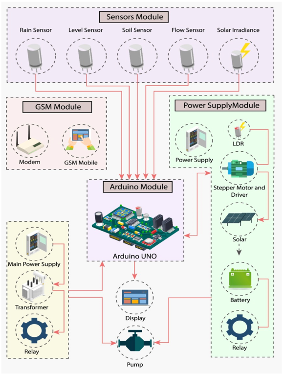
2. Approach and Methodology
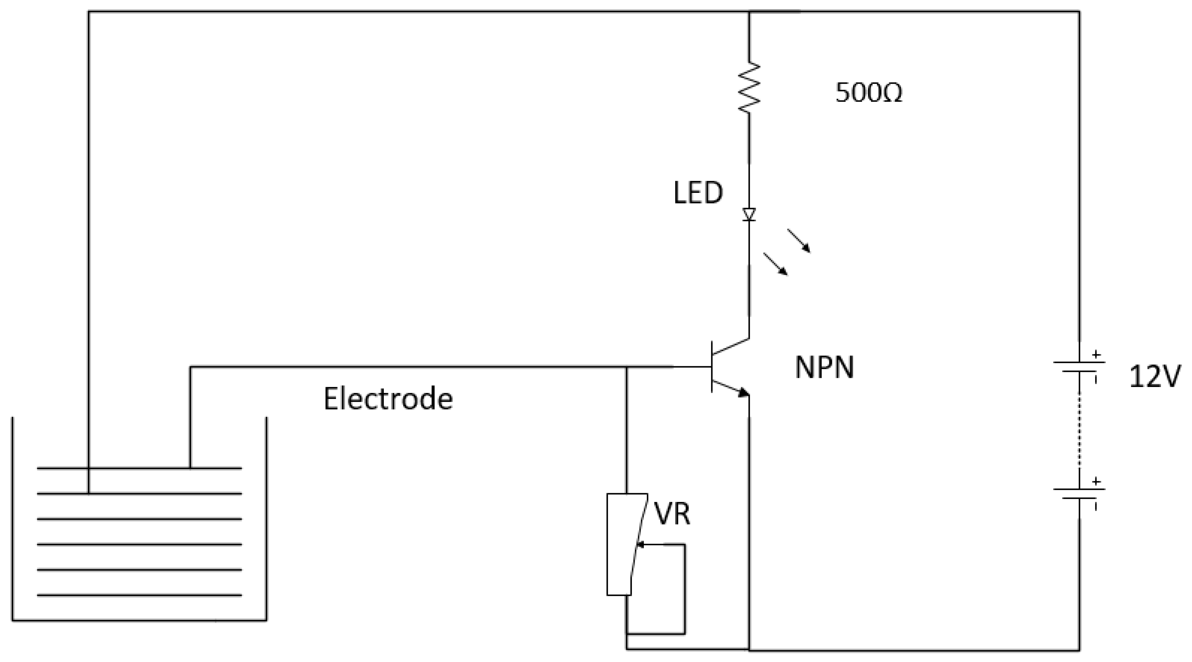
Agriculture fields are located far away from the farmers’ residence, and it is difficult for them to visit a few times a day to turn on and off the motor to guard crops against improper irrigation and unconditional rain. To resolve these issues, a smart-sensors-based solar-powered system for smart irrigation is developed, which will be discussed in detail in this section. The designed system monitors and controls water flow to the field by turning on and off the motor based on weather and field conditions. The developed framework comprises Arduino with a built-in Atmel ATmega microcontroller module, sensors (humidity, soil, moisture, rain, level, flow, etc.) module, solar power module, and GSM module, as shown in Figure 1. The Arduino microcontroller module works as a central control device in the developed framework. The sensors modules acquire data. The acquired data are sent to the analog-to-digital converter (ADC) of the microcontroller. The microcontroller makes the decision based on the received data from the sensors to either switch on or off the motor via a digital signal generated at its digital I/O pin. The decision taken by the microcontroller is communicated via the GSM module to the operator/user via SMS. The operator/user can remotely control the motor via handset and also view the operation status via a handset upon receiving acknowledgments of the sent commands. In addition, LCD is used to view the operation status and various parameters under consideration. The developed system works on 12 v DC supply due to the Arduino. Therefore, 220 v AC supply is converted to 12 v DC to operate the system and is also initially used to power up the AC pump to fill the tube well. The solar power module generates 12 v DC, which is used to power a submersible pump to push the water from the well to agriculture fields for irrigation. Relays are used to control the switching of motors. All data recorded of the whole process are shared with the user via SMS. The tube well pump is turned on and off as per the decision taken by the microcontroller based on the weather, field, and water conditions.
The whole process is shown in Figure 2 via a flow chart. An SMS about the status of the motor is sent back as an acknowledgment to the user. The flow chart of the controlled sequence commands to operate tube well in manual or automatic mode is depicted in Figure 3. To check the feasibility of the smart-sensors-based solar-powered system, aspects of availability, cost, various sensors, voltage converters, motors, and other performance parameters are evaluated. The components are selected based on careful evaluation, which is used in the developed framework. Furthermore, all components used in the developed system are initially simulated to analyze and check its feasibility and functionality. This simulation analysis facilitated us to develop the design of a smart-sensors-based solar-powered system with minimal effort and time. Both the simulation (software) and prototype’s (hardware) current design with mathematical relationships and explanation are elaborated as follows:

2.1. Sensors Module

In this subsection, the sensors module is discussed in detail. The sensors module has various sensors, such as moisture, soil, level (shown in Figure 4), humidity (depicted in Figure 5), flow, rain, etc., that measure the physical quantity and give an output in the same format. Some sensors operate on batteries returning an electrical signal at the output that varies with the physical quantity.
Dominant parameters in selecting the sensors are the operation range, resolution, accuracy, cost, and suitability for the underlying problem. For example, the temperature sensor measures temperatures up to 100 °C. This sensor is sufficient for the measurement of outdoor temperature but not suitable for temperature measurements up to 1000 °C, which is the required temperature for boiling liquids. While choosing sensors, there is a tradeoff between accuracy and price. Thus, users can choose suitable sensors depending upon the system requirements and budget. Electronic sensors have three pins, i.e., gnd for ground, Vcc for power, and out for output. These pins may either be analog or digital. A complete discussion of sensors used in our proposed system is as follows:

Water Flow Sensor

Water flow sensors operate using a 5–24 V DC and generate pulses on digital output pin as output. This sensor works on the Hall-effect phenomenon, which is connected in line with the waterline, as depicted in Figure 6. The pinwheel inside the sensor moves with frequency and water counter increments per revolution. The generated output is fed to the Arduino on the digital I/O pin that computes the flow rate as per the mathematical model.
Q = pulse   frequency 7.5
where Q represents flow rate measured in liters per minute, and the pulse frequency is measured in hertz.

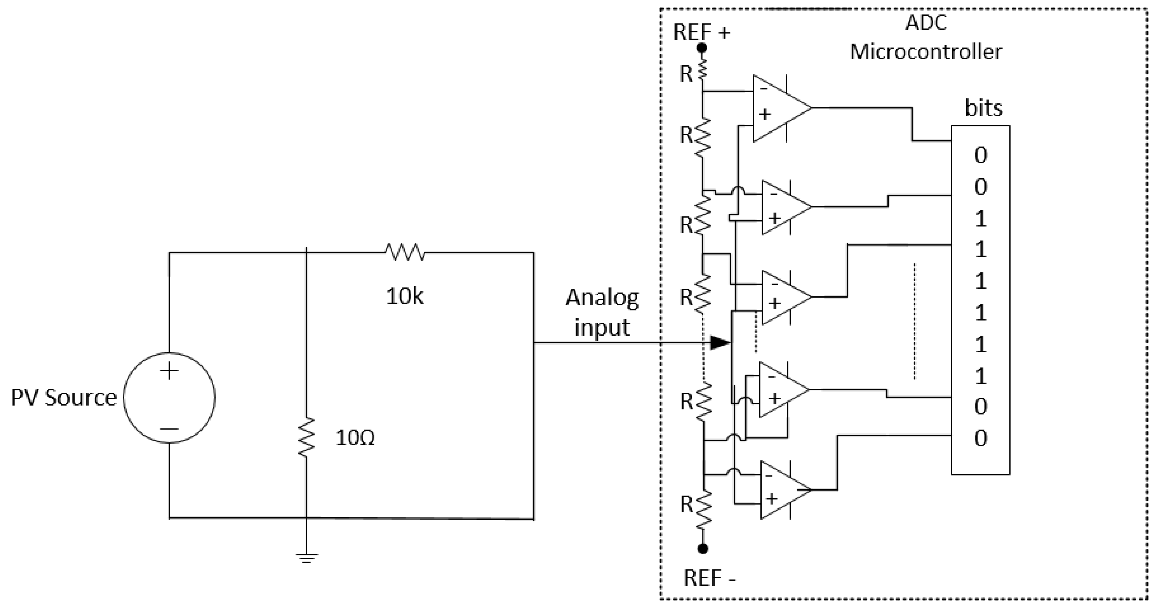
2.2. Irradiance Measurement

Solar irradiance is measured in watts per meter square. Solar cell output current is directly proportional to solar irradiance. On the other hand, the voltage of each cell is independent of the solar irradiance and is approximately 0.5 to 0.6 v, known as the open-circuit voltage (Voc) of a solar cell. The feasibility analysis facilitates users in choosing the optimal location and suitable solar panel for the developed system. The Arduino, via the analog channel, receives the solar cell output voltage. An appropriate resistor is connected with Arduino and solar cell in series to measure the appropriate irradiance, as shown in Figure 7.
The ADC shown in Figure 8 converts the signal to voltage, and the mathematical relationship implemented is defined as
R   =   P / A
where R represents irradiance, and A denotes solar cell/panel (i.e., panel width x panel length/10,000) total area.
The power is computed as follows:
P = V 2 R
where V represents analog voltage read by ADC, and R denotes connected resistance connected across analog input.

2.3. Solar-Powered Water Pump

This work uses a solar-powered pump with the following specifications: maximum power rating   P max = 8 watts, maximum height of 5 m, where the motor can lift 10 L of water per minute operating at a voltage of 12 v. Solar cells are chosen that are feasible for the operation of motor with the above specifications. The quality of solar panel is evaluated via efficiency, which is measured as follows:
%   Efficiency = p max A   × 1000   ×   100
where   P max denotes solar panel maximum power output, A represents the solar panel total area, and the size of used solar panel is 7″ × 11″. The efficiency of the solar panel at the above discussed specification is 16.1%.

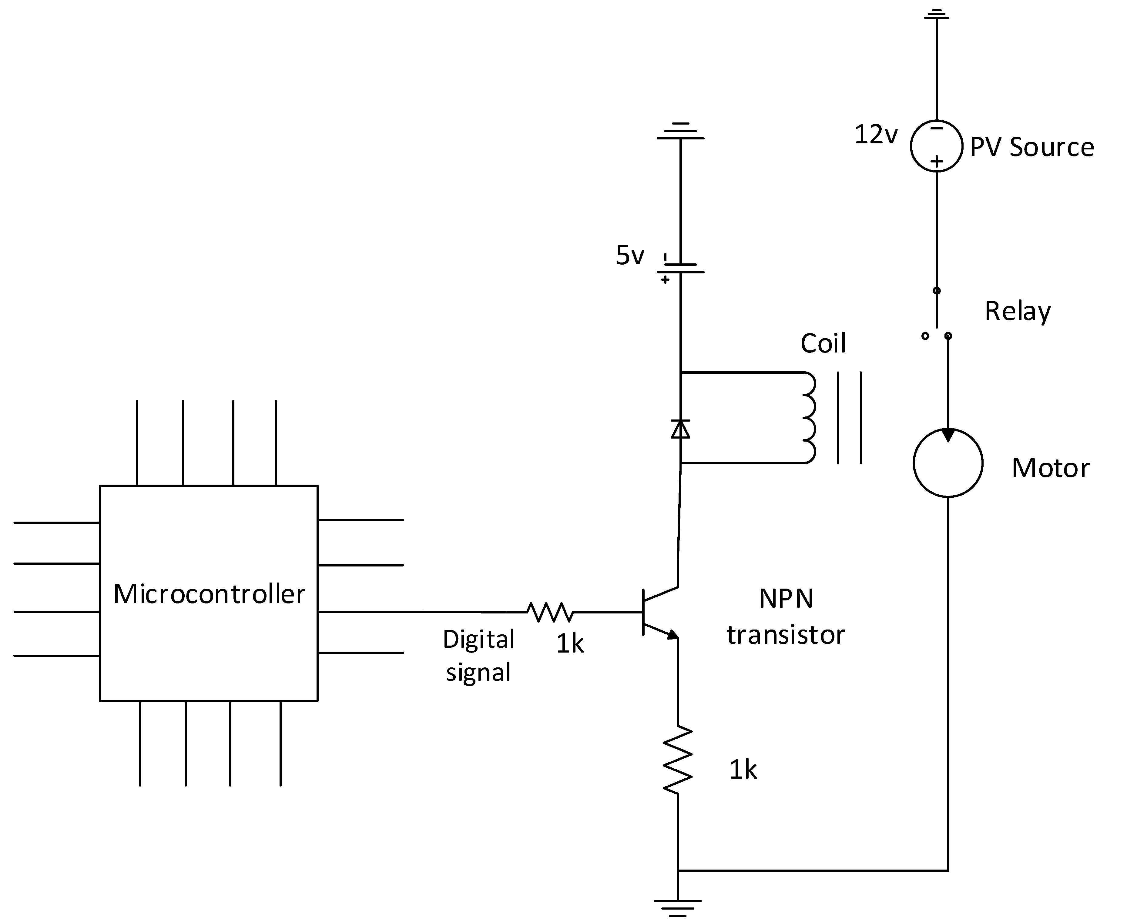
2.4. Motor Switching
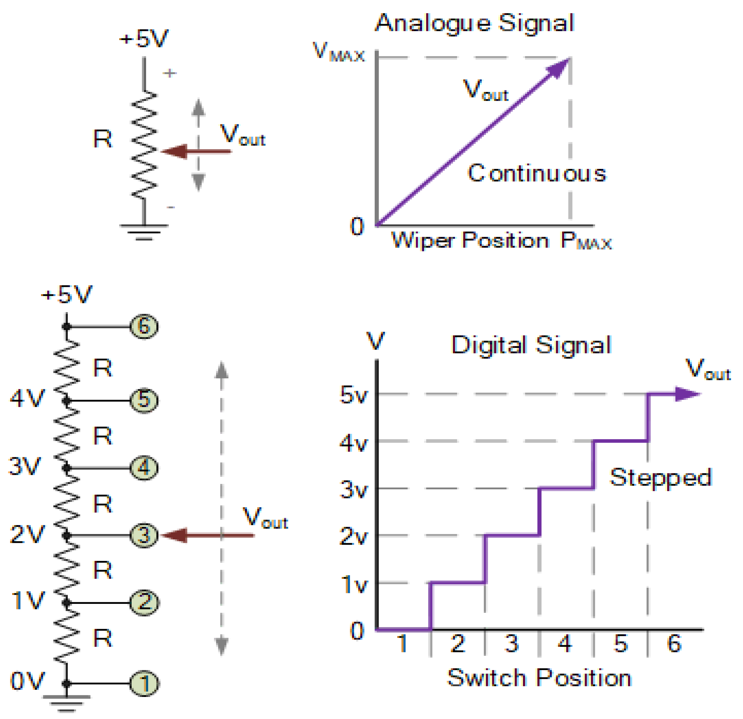
The developed system mainly controls motor operation based on specific conditions, such as weather and environmental conditions (rain, temperature, irradiance, humidity, etc.), soil conditions (wet or dry), and crop conditions to monitor and regulate water flow accordingly to minimize water and energy consumption wastage. For instance, the motor will be turned on when the soil is dry, and the tube well has sufficient water; otherwise, it will remain off. The switching circuitry employed for this purpose is shown in Figure 8. A transistor is used as a switch in the switching circuitry, and it has three operation regions: cut-off, linear, and saturation region. The microcontroller decides to either turn on or off the motor. The microcontroller issues a command to turn on the motor. It generates a high signal on the I/O pin, which drives the base to operate the transistor in a saturation region that energizes the relay to shift from a normally closed (NC) position to a normally open (NO) position, which makes a path for the current flow. As a result, the motor will be turned on. In contrast, when the motor turn-off command is fed to a microcontroller, it sets the I/O pin to low, removing the base signal from the transistor that operates it in the cut-off region. Consequently, the motor will be turned off. The LCD will display the on or off status of the motor for visualization.

2.5. ADC

ADC is a device used to convert an analog signal to a digital signal by converting continuous amplitudes to fixed discrete levels. The working mechanism of ADC is visualized in Figure 9. This work used sensors whose outputs are analog signals that must be converted to digital signals before feeding to the microcontroller. The Arduino has on-chip ADCs with 10-bit resolution. Thus, ADCs assign 1024 discrete, distinct levels to each incoming analog signal. The higher the resolution, the better the accuracy. The ADCs conversion is formulated as follows:
D out = 2 n 1 ×   V in V ref
where V ref represents reference analog voltage, and D out denotes the digital value of the corresponding analog input voltage V in .
To convert the obtained digital value to an analog value, rearranging Equation (5), we obtain Equation (6), which ensures conversion as follows:
V in =   D out × V ref 2 n 1

2.6. Voltage Regulator

Voltage regulators are of two types: (i) linear regulators and (ii) switching regulators. Linear regulators use variable resistances to regulate and maintain the constant output voltage. Positive (78xx) and negative (79xx) voltage regulators are examples of linear regulators. In positive and negative regulators, input voltage > output/desired regulated voltage. In contrast, switching regulators turn on/off transistors at different intervals for maintaining a constant/regulated output voltage. In switching regulators, input voltage < or > output voltage/regulated voltage, e.g., buck and boost converter. Moreover, it is obvious from Figure 10 that the efficiency of the linear regulator is constant for the same amount of output current. In contrast, a switching converter has higher efficiency and improves with the increase in current. Switching regulators are more effective and efficient than linear regulators, as depicted in Figure 11. For instance, a regulator with 24 v input voltage and 1A load generates a 6 v constant output voltage resulting in input power Pin = Vin × Iin = 24 W and output power Pout = 6 V × 1 A= 6 W returning 25% efficiency (% efficiency = Pout/Pin), dissipated power Pd = 24 − 6 = 18 W. Thus, more power is dissipated while performing regulation than the power consumed, which raises the junction temperature. In this work, we use a linear voltage regulator due to the following reasons: (i) devices input voltages and output voltages do not have enough difference, (ii) low noise, cost, and simple circuit configuration.

3. Experimental Setup, Results, and Discussion

First, the proposed smart irrigation framework is designed and implemented in Proteus software, as depicted in Figure 11. The developed framework has four modules such as a controller module, power supply module, GSM module, and sensors module. The controller module has Arduino with a built-in ATmega-328 microcontroller, the power supply module has main supply/PV panels, the GSM module is SIM900D, and the sensors module has soil moisture, temperature, humidity, level, and rain detection sensors. The controller module is the main part, which monitors the whole irrigation process. The purpose of this implementation is to test and select the efficient system’s parameters. The change in the behavior of components under different conditions (environmental conditions) was taken and kept under consideration. For example, the linear regulator has much significant power dissipation when its input voltage is more than double the output voltage. In other words, the more significant the difference in voltages, the larger the power dissipation. Since the used sensors operate on 5 v, a 7805 linear voltage regulator is used in the proposed system. A heat sink is also placed for excessive heat absorption. After testing and analyzing via simulations, appropriate hardware components are selected, and a hardware prototype is developed. The hardware components used for prototype development are as follows: PC with Arduino software, Arduino ATmega-328, soil moisture sensor (YL 69), humidity and temperature sensor (DHT22), rain level monitoring sensor, GSM module (SIM900D), relays, solar PV panels, LCD, and pumps. The specifications of the developed system are listed in Table 2 as follows:
The developed system is tested on six square meter field irrigation from 7 June to 13 July 2021. The proposed system’s complexity analysis depends on system hardware (Arduino), compiler efficiency, operating system, and inputs size. The complexity analysis results are listed in Table 3. The complexity is mainly illustrated from the execution time and average CPU usage. The execution time is the time taken by the Arduino to run a program to find the irrigation time, which is 10−14 s in our case. The whole system occupies 65% of Arduino CPU.
The management of monitoring the tube wells and controlling the water provision for the land was conducted using different electronic sensors. To make smart decisions according to the measured values, the received data from sensors are fed into Arduino. The system values are determined from ADC measured values, so the system’s performance depends on ADC. The results, along with their verification, are given in Figure 12. As we can see, the user receives the status of every parameter through an SMS.
The results of the proposed smart irrigation system under various operating conditions are listed in Table 4 and Table 5, respectively. The motor is turned on under no-rain conditions and dry soil to irrigate the crops. Before switching the motor on, solar irradiance is also checked to know if enough solar energy is available to switch on the motor. The water flow rate is also monitored through a preinstalled sensor to see the amount of water running into the field. The measured water flow rate was 10 L/min.
Once the motor starts, it will remain on until one of the three conditions is satisfied, i.e., either rain occurs or the water level in the field reaches a defined level, irradiance falls below a threshold value, or the utility supply is unavailable.
The user receives an SMS alert whenever any of the system parameters change. Moreover, the motor can also be turned on or off by the user remotely through an SMS sent to the system. After receiving an SMS, the system will first authenticate the user by matching the number with the previously saved ones in the Arduino microcontroller memory. The request is processed only if the user is valid. The request is automatically discarded in the case of an invalid user. Similarly, an authenticated user can also request data acquired by the system. The requested data are sent to the user as well as to the LCD screen installed for display, as shown in Table 6.
After receiving the data, if for any reason the user wants to turn the motor off, he can do so by sending turn off command to the system.
The evaluation of the system was done based on accuracy of the installed sensors in terms of their measured values. The measured quantity is converted into output voltage and then plotted against each other to obtain a graph. Figure 13 illustrates the measurement of the soil sensor for our 10-bit ADC, i.e., for n = 10, 2 10 1 = 1023, as follows:
A out = D o 1023
where   A out represents analog output voltage and D o denotes ADC value.
Percentage moisture in the soil is measured as follows:
M   = 100 ( A out   ×   100 )
where M represents percentage moisture in the soil.
As seen in Figure 13, percent moisture in the soil is inversely proportional to the ADC output voltage values. The ADC voltage output value is maximal (5 V) for no moisture (0% moisture) and vice versa. The observed values of soil moisture are shown in Figure 13. These results can also be used for measuring the deficiency of irrigation water, using the following expression:
S d = S wf S wc
where S d represents the water depletion of soil in inches, S wf denotes the water content of soil at field capacity in inches, and S wc indicates the current water content of soil.
The linear behavior between the volume of water and ADC output values is shown in Figure 14.
A rectangular tank of height ‘h’ and width ‘w’ of 1 m was considered to calculate the threshold level or depth ‘d’ for water level sensor. The water volume V in the tank can be calculated using the relation V = h × l × d under step size 1/1024 = 0.00097. This indicates that every one degree change in ADC corresponds to one degree change in depth. Thus, the height and width are constant if an ADC reads the 512 value than V = 0.4964   m 3   (i.e., [512 × 0.00097] × 1 × 1) or 496.4 L. The water level threshold for turning the motor on and off can be set easily after determining the depth ‘d’. Rain detection can also be done using the same sensor. In this case, the need to calculate the threshold depth is omitted because the sensor will automatically generate an output after sensing raindrops.

4. Discussion

Many models in the literature have been proposed, which rely only on utility supply. Since solar energy is used by both the proposed model and [65], some similarities and differences can be highlighted with existing systems. Firstly, both models used different sensors for data collection and GSM technology for communication to automate irrigation. Also, both models used a central controller (microcontroller) for making smart decisions. Secondly, both models achieved excellent results in terms of the measurement and accuracy of sensors, water, and energy consumption minimization. However, in [65], some confrontations can be seen with low daylight. The blustery/windy climate was also an issue. The problem with low sunlight means low irradiance, which means lesser solar power output, leading to motor operation below its rated value. This problem was addressed in our system by constantly monitoring solar irradiance. As the irradiance falls below a threshold and enough solar energy is not available to operate the motor, the motor is automatically turned off. This issue can also be addressed by adding a maximum power point tracking technique. At maximum power point, specific voltage and current values are calculated, as shown in Figure 15. The blue and green lines show current–voltage and power–voltage relations, respectively. It is evident from the graphs that in the case of partial shading or low irradiance, the power drop from the maximum value is significant. In contrast, there is no power drop in the case of no shading, and at high irradiance, the power is maximal. To further elaborate on this concept, as shown in Figure 16a, five different irradiances with values ranging from 600 W/m2 to 1400 W/m2 and a step size of 200 are taken at a fixed temperature of 250 °C. The results indicate that current and power are directly proportional to the irradiance. Furthermore, it also helps to select suitable solar panels for the system. Similarly, five different temperatures ranging from 12–350 °C with a step size of 50 °C were taken at fixed solar irradiance of 1000 W/m2. The results indicate that current and voltage are in inverse proportion with the temperature, as shown in Figure 16b. Furthermore, it also helps in the selection of suitable solar panels for the developed smart irrigation system. A water level sensor is also installed in the well to show the status of the water level in the well to prevent the motor from dry running. Hence, if the water level in the well falls below the motor level, the motor will remain off, even if the soil is dry and there is no rain. This sensor will also help to monitor the availability of water deep inside the earth.
In a nutshell, the many available smart irrigation systems [13,14,15,16,17,18,19,20,21,22,23,24,25,26,27,28,29,30,31,32,33,34,35,36,37,38,39,40,41,42,43,44,45] proposed previously achieved remarkable results. However, they lacked system protection analysis and did not have any selection criteria for devices’ selection for a particular task. We introduced criteria and techniques that fix these issues and eventually help the smart automation communities enhance their system performance.
We analyzed the solar panel efficiency and utilized it in the developed system for smart irrigation. Motor protection is ensured by measuring irradiance and setting up threshold criteria that ensure optimized operation. Furthermore, voltage regulators were compared on the basis of power dissipation and utilization. Their suitability for different operating conditions was also studied. This analysis helps design solar and non-solar powered smart irrigation systems with limited energy resources and power efficient devices.
To endorse the results of the proposed system, a comparison is conducted in aspects of performance with existing models, such as [65,66,67]. These systems are selected as benchmark due to architectural similarities with the proposed system. For fair evaluation, conditions, parameters, and duration for the proposed and existing systems are kept the same.
The water consumed and time spent by actuators of the proposed and existing models are shown in Table 7. Results show that the developed model consumed least amount of water than existing models, such as [65,66,67]. Additionally, the proposed model actuators operating time recorded is less than that of existing models [65,66,67]. On the record, the proposed system consumed water at 580 L/day, which is the least compared to existing models.
The proposed smart irrigation system and existing systems, such as [65,66,67], estimated water and energy consumption for the duration of four months is depicted in Figure 17. A four-month duration is adopted because the four-month time is the optimal time required for the maturation of crops. It is evident from the results that the amount of water and energy consumed by the proposed system is considerably less than that of systems such as [65,66,67]. The developed system is advantageous in aspects of water and energy consumption minimization, even when huge/large agriculture areas are considered.
The water and energy consumed by the proposed and existing models are listed in Table 8. Results show that the proposed smart irrigation system considerably reduced water and energy consumption compared to existing models, such as [56,65,67], which is 45 L and 29 Wh, respectively. The resultant findings show that the proposed smart irrigation system is the most suitable option for the farmer to irrigate crops.
Table 9 shows the results of the proposed and existing systems in aspects of relative difference between water and energy cost that the farmer pays as per the real price defined by the irrigation authorities for the duration of 4 months. According to the listed results, the proposed system can save 45.35%, 28.20% and 68.25% in costs compared to [65], [66], and [67], respectively.
From the results and discussions, we are convinced that the proposed smart irrigation system is efficient in aspects of cost, water, and energy savings, compared to existing systems, such as [65,66,67]. It is difficult to estimate the exact percentage improvement because for precise estimation comparison, several scales and various aspects are needed, which is difficult because each system has its pros and cons. However, the concluding remarks are as follows:
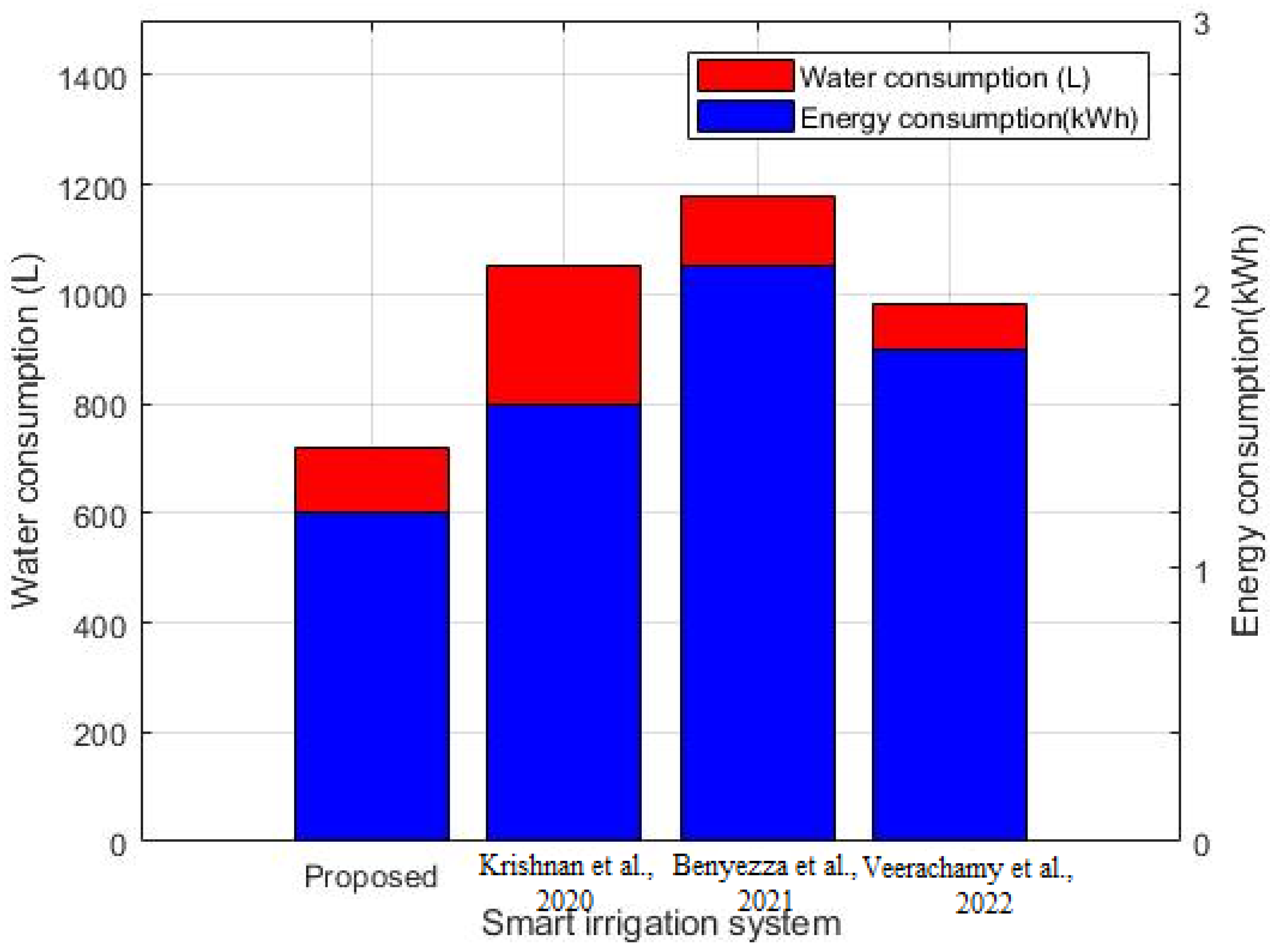
  • The obtained results listed in Table 7 illustrate that the proposed smart irrigation system takes 41.7%, 20.89%, and 14.92% less time compared to existing systems, such as [65], [66], and [67], respectively. Additionally, the capital cost of the proposed approach is nearly 10% less than the existing systems, such as [65], [66], and [67], respectively.
  • The obtained comparative results (proposed and existing ([65,66,67]) listed in Table 9 show that the proposed system gives an improvement in water and energy consumption of 51.1% and 44.82% compared to [65], 35.5% and 31.0% compared to [66], 26.6% and 20.6% compared to [67], respectively.
From the above discussion, we conclude that the proposed smart irrigation system is the most suitable system for farmers to irrigate the crops in their fields, which will return savings in terms of cost, time, water, and energy.

5. Conclusions

This research focused on the serious issue of water and energy loss during irrigation and proposed an optimal solution to the problem by developing a low-cost smart-sensor-based solar-powered irrigation system. The proposed smart irrigation system has four modules: Arduino with a built-in ATmega microcontroller, sensors, solar power/utility, and GSM. The Arduino microcontroller module takes input from different sensors such as soil moisture, rain, humidity, and water level sensors installed in the field. The Arduino makes a decision based on the information received from the sensor module. The Arduino will send a command to turn on the tube well if the soil is dry, there is no rain, and the crops need water. The Arduino will send a command to turn off the tube well when the water level reaches the desired level, conserving water and saving crops from over-irrigation. A sensor installed in the well also prevents the motor from dry running and ultimately overheating. An LCD screen is also installed, which shows the status of the motor and sensors. The GSM module installed conveys all this information to the user located remotely. The user can also enquire about the status of the tube well (on or off) and sensors using his cellphone. It is worth mentioning here that primarily, the system works on solar power. Overall, the proposed system is economical (as the sensors are low cost and operation cost is also zero), reliable, and easily deployable. The proposed system saves a lot of time, money, energy, and water. It also reduces the need for more human resources, as it is smart, automatic, and user friendly. Even someone with just basic cellphone know-how can use it without any inconvenience. Results show that the proposed system is superior to existing systems in terms of water wastage, energy consumption, and cost minimization, and revolutionizes the existing irrigation system.
This work can be extended in future in the following directions:
  • The controller will be programmed based on the Lyapunov optimization technique to solve the irrigation scheduling problem in real time, where on-field events and requests will be responded to for effective irrigation.
  • A Lyapunov-optimization-technique-based controller will be employed in fog- and cloud-based environments to solve the irrigation scheduling problem under dynamic and uncertain conditions for remote fields that the farmer is unable to access.

Author Contributions

Conceptualization, methodology, software, validation, formal analysis, investigation, resources, data curation, S.U., G.R., S.K., G.H., K.R. and S.M.; writing—original draft preparation, S.U., F.A.K., F.A. and G.H.; writing—review and editing, visualization, supervision, F.A., F.R.A. and G.H.; project administration, funding acquisition, F.R.A., F.A.K. and G.H. All authors have read and agreed to the published version of the manuscript.

Funding

The APC is supported by the Taif University Researchers Supporting Project Number (TURSP-2020/331), Taif University, Taif, Saudi Arabia.

Institutional Review Board Statement

Not applicable.

Informed Consent Statement

Not applicable.

Data Availability Statement

Not applicable.

Acknowledgments

The authors would like to acknowledge the support from Taif University Researchers Supporting Project Number (TURSP-2020/331), Taif University, Taif, Saudi Arabia.

Conflicts of Interest

The authors declare no conflict of interest.

Abbreviations and Acronyms

AbbreviationsExplanation
GSMGlobal System for Mobile Communication
FLFuzzy Logic
IoTInternet of Things
PICPeripheral Interface Controller
SMSShort Messaging Service
LCDLiquid Crystal Display
LDRLight Dependent Resistor
SVRSupport Vector Regression
GPRSGeneral Packet Radio Service
ADCAnalog-to-Digital Converter
DCDirect Current
ACAlternating Current
I/OInput/Output
NONormally Open
NCNormally Closed
SIMSubscriber Identity Module
PVPhotovoltaic
PCPersonal Computer
CPUCentral Processing Unit
RAMRandom Access Memory
GndGround
VccVoltage Common Collector
VocOpen Circuit Voltage
QFlow rate in liters/minute
EIrradiance
PElectrical Power
AArea
RResistance
VVoltage
VinInput Voltage
Iin Input Current
PmaxMaximum Electrical Power
PdDissipated Power
DoutDigital Value of Input Voltage
VrefReference Analog Voltage
AoutAnalog Output Voltage
DoADC Reference Voltage
MPercentage Moisture in Soil
SdWater Depletion of Soil in Inches
SwfContent of Soil at Field Capacity in Inches
SwcCurrent Water Content of Soil
VVolume of the Tank
HHeight of Tank
WWidth of the Tank
DDepth of the Tank
WhWatt Hours

References

  1. Khan, M.H. Agriculture in Pakistan: A Revisit. Pak. Dev. Rev. 2020, 59, 115–120. [Google Scholar] [CrossRef]
  2. Muangprathub, J.; Boonnam, N.; Kajornkasirat, S.; Lekbangpong, N.; Wanichsombat, A.; Nillaor, P. IoT and agriculture data analysis for smart farm. Comput. Electron. Agric. 2019, 156, 467–474. [Google Scholar] [CrossRef]
  3. Tariq, M.; Van De Giesen, N.; Janjua, S.; Shahid, M.; Farooq, R. An Engineering Perspective of Water Sharing Issues in Pakistan. Water 2020, 12, 477. [Google Scholar] [CrossRef] [Green Version]
  4. Yang, Y.; Peng, J.C.; Ye, C.; Ye, Z.; Ding, Y. A Criterion and Stochastic Unit Commitment towards Frequency Resilience of Power Systems. IEEE Trans. Power Syst. 2021, 37, 640–652. [Google Scholar] [CrossRef]
  5. Gondchawar, N.; Kawitkar, R.S. IoT based smart agriculture. Int. J. Adv. Res. Comput. Commun. Eng. 2016, 5, 838–842. [Google Scholar]
  6. Sakthipriya, N. An effective method for crop monitoring using wireless sensor network. Middle-East J. Sci. Res. 2014, 20, 1127–1132. [Google Scholar]
  7. Zhang, N.; Wang, M.; Wang, N. Precision agriculture—A worldwide overview. Comput. Electron. Agric. 2002, 36, 113–132. [Google Scholar] [CrossRef]
  8. Khanna, A.; Kaur, S. Evolution of Internet of Things (IoT) and its significant impact in the field of Precision Agriculture. Comput. Electron. Agric. 2019, 157, 218–231. [Google Scholar] [CrossRef]
  9. Li Johansson, E.; Fader, M.; Seaquist, J.W.; Nicholas, K.A. Simulating potential water grabbing from large-scale land acquisitions in Africa. In Proceedings of the 19th EGU General Assembly Conference Abstracts, Vienna, Austriap, 23–28 April 2017; p. 9285. [Google Scholar]
  10. Doungmanee, P. The nexus of agricultural water use and economic development level. Kasetsart J. Soc. Sci. 2016, 37, 38–45. [Google Scholar] [CrossRef] [Green Version]
  11. Velasco-Muñoz, J.; Aznar-Sánchez, J.; Belmonte-Ureña, L.; Román-Sánchez, I. Sustainable Water Use in Agriculture: A Review of Worldwide Research. Sustainability 2018, 10, 1084. [Google Scholar] [CrossRef] [Green Version]
  12. Papageorgiou, E.I.; Kokkinos, K.; Dikopoulou, Z. Fuzzy sets in agriculture. In Fuzzy Logic in Its 50th Year; Springer: Cham, Switzerland, 2016; pp. 211–233. [Google Scholar]
  13. Cao, B.; Zhao, J.; Liu, X.; Arabas, J.; Tanveer, M.; Singh, A.K.; Lv, Z. Multiobjective Evolution of the Explainable Fuzzy Rough Neural Network with Gene Expression Programming. IEEE Trans. Fuzzy Syst. 2022. [Google Scholar] [CrossRef]
  14. Zhang, L.; Zheng, H.; Cai, G.; Zhang, Z.; Wang, X.; Koh, L.H. Power-frequency oscillation suppression algorithm for AC microgrid with multiple virtual synchronous generators based on fuzzy inference system. IET Renew. Power Gener. 2022, 16, 1589–1601. [Google Scholar] [CrossRef]
  15. Bahat, M.; Inbar, G.; Yaniv, O.; Schneider, M. A fuzzy irrigation controller system. Eng. Appl. Artif. Intell. 2000, 13, 137–145. [Google Scholar] [CrossRef]
  16. Touati, F.; Al-Hitmi, M.; Benhmed, K.; Tabish, R. A fuzzy logic based irrigation system enhanced with wireless data logging applied to the state of Qatar. Comput. Electron. Agric. 2013, 98, 233–241. [Google Scholar] [CrossRef]
  17. Li, M.; Sui, R.; Meng, Y.; Yan, H. A real-time fuzzy decision support system for alfalfa irrigation. Comput. Electron. Agric. 2019, 163, 104870. [Google Scholar] [CrossRef]
  18. Ibrahim, F.S.; Konditi, D.; Musyoki, S. Smart irrigation system using a fuzzy logic method. Int. J. Eng. Res. Technol. 2018, 11, 1417–1436. [Google Scholar]
  19. Izzuddin, T.A.; Johari, M.A.; Rashid, M.Z.A.; Jali, M.H. Smart irrigation using fuzzy logic method. ARPN J. Eng. Appl. Sci. 2018, 13, 1819–6608. [Google Scholar]
  20. Ponnusamy, R.; Rajaprakash, S.; Jaichandran, R. Fuzzy Logic Controller for Effective Irrigation Based on Field Soil Moisture and Availability of Water. J. Adv. Res. Dyn. Control. Syst. 2017, 9, 90–97. [Google Scholar]
  21. Villarrubia, G.; De Paz, J.F.; De La Iglesia, D.H.; Bajo, J. Combining Multi-Agent Systems and Wireless Sensor Networks for Monitoring Crop Irrigation. Sensors 2017, 17, 1775. [Google Scholar] [CrossRef] [Green Version]
  22. Cao, B.; Zhang, Y.; Zhao, J.; Liu, X.; Skonieczny, L.; Lv, Z. Recommendation Based on Large-Scale Many-Objective Optimization for the Intelligent Internet of Things System. IEEE Internet Things J. 2021, 9, 15030–15038. [Google Scholar] [CrossRef]
  23. Rajkumar, M.N.; Abinaya, S.; Kumar, V.V. Intelligent irrigation system—An IOT based approach. In Proceedings of the 2017 International Conference on Innovations in Green Energy and Healthcare Technologies (IGEHT), Coimbatore, India, 16–18 March 2017; pp. 1–5. [Google Scholar]
  24. Difallah, W.; Benahmed, K.; Bounnama, F.; Draoui, B.; Saaidi, A. Intelligent Irrigation Management System. Int. J. Adv. Comput. Sci. Appl. 2018, 9. [Google Scholar] [CrossRef]
  25. Liu, S.; Guo, L.; Webb, H.; Yao, X.; Chang, X. Internet of Things Monitoring System of Modern Eco-Agriculture Based on Cloud Computing. IEEE Access 2019, 7, 37050–37058. [Google Scholar] [CrossRef]
  26. Narvekar, P.R.; Kumbhar, M.M.; Patil, S.N. Grape leaf diseases detection & analysis using SGDM matrix method. Int. J. Innov. Res. Comput. Commun. Eng. 2014, 2, 3365–3372. [Google Scholar]
  27. Zhang, L.; Wang, X.; Zhang, Z.; Cui, Y.; Ling, L.; Cai, G. An adaptative control strategy for interfacing converter of hybrid microgrid based on improved virtual synchronous generator. IET Renew. Power Gener. 2021, 16, 261–273. [Google Scholar] [CrossRef]
  28. Yu, D.; Ma, Z.; Wang, R. Efficient Smart Grid Load Balancing via Fog and Cloud Computing. Math. Probl. Eng. 2022, 2022, 3151249. [Google Scholar] [CrossRef]
  29. Liu, J.; Yin, Y.; Wang, K.; Wei, P.; Lu, H.; Song, C.; Liang, Q.; Huang, W. Domain size control in all-polymer solar cells. iScience 2022, 25, 104090. [Google Scholar] [CrossRef]
  30. Zhang, Y.; Shi, X.; Zhang, H.; Cao, Y.; Terzija, V. Review on deep learning applications in frequency analysis and control of modern power system. Int. J. Electr. Power Energy Syst. 2022, 136, 107744. [Google Scholar] [CrossRef]
  31. Shang, L.; Dong, X.; Liu, C.; Gong, Z. Fast Grid Frequency and Voltage Control of Battery Energy Storage System Based on the Amplitude-Phase-Locked-Loop. IEEE Trans. Smart Grid 2022, 13, 941–953. [Google Scholar] [CrossRef]
  32. Navarro-Hellín, H.; Martínez-Del-Rincon, J.; Domingo-Miguel, R.; Soto-Valles, F.; Torres-Sánchez, R. A decision support system for managing irrigation in agriculture. Comput. Electron. Agric. 2016, 124, 121–131. [Google Scholar] [CrossRef] [Green Version]
  33. Rawal, S. IOT based smart irrigation system. Int. J. Comput. Appl. 2017, 159, 7–11. [Google Scholar] [CrossRef]
  34. Barker, J.B.; Heeren, D.M.; Neale, C.M.; Rudnick, D.R. Evaluation of variable rate irrigation using a remote-sensing-based model. Agric. Water Manag. 2018, 203, 63–74. [Google Scholar] [CrossRef] [Green Version]
  35. Zhang, B.; Jiang, H.-F.; Han, X. Study on Corn Water Saving Irrigation Decision-making Model. Adv. J. Food Sci. Technol. 2015, 9, 9–12. [Google Scholar]
  36. Sami, M.; Khan, S.Q.; Khurram, M.; Farooq, M.U.; Anjum, R.; Aziz, S.; Qureshi, R.; Sadak, F. A Deep Learning-Based Sensor Modeling for Smart Irrigation System. Agronomy 2022, 12, 212. [Google Scholar] [CrossRef]
  37. Katta, S.; Ramatenki, S.; Sammeta, H. Smart irrigation and crop security in agriculture using IoT. In AI, Edge and IoT-Based Smart Agriculture; Academic Press: Cambridge, MA, USA, 2022; pp. 143–155. [Google Scholar] [CrossRef]
  38. López-Andreu, F.J.; López-Morales, J.A.; Erena, M.; Skarmeta, A.F.; Martínez, J.A. Monitoring System for the Management of the Common Agricultural Policy Using Machine Learning and Remote Sensing. Electronics 2022, 11, 325. [Google Scholar] [CrossRef]
  39. Ahansal, Y.; Bouziani, M.; Yaagoubi, R.; Sebari, I.; Sebari, K.; Kenny, L. Towards Smart Irri-gation: A Literature Review on the Use of Geospatial Technologies and Machine Learning in the Management of Water Re-sources in Arboriculture. Agronomy 2022, 12, 297. [Google Scholar] [CrossRef]
  40. Chauhan, A.; Sah, R.R.; Khatri, R. IoT-Based Smart Irrigation System—A Hardware Review. In IOT with Smart Systems; Springer: Singapore, 2022; pp. 647–659. [Google Scholar]
  41. Vivekanandhan, V.; Sakthivel, S.; Manikandan, M. Adaptive neuro fuzzy inference system to enhance the classification performance in smart irrigation system. Comput. Intell. 2021, 38, 308–322. [Google Scholar] [CrossRef]
  42. Rehman, A.U.; Asif, R.M.; Tariq, R.; Javed, A. Gsm based solar automatic irrigation system using moisture, temperature and humidity sensors. In Proceedings of the 2017 International Conference on Engineering Technology and Technopreneurship (ICE2T), Kuala Lumpur, Malaysia, 18–20 September 2017; pp. 1–4. [Google Scholar]
  43. Kansara, K.; Zaveri, V.; Shah, S.; Delwadkar, S.; Jani, K. Sensor based automated irrigation system with IOT: A technical review. Int. J. Comput. Sci. Inf. Technol. 2015, 6, 5331–5333. [Google Scholar]
  44. Ishak, S.; Malik, N.A.; Latiff, N.A.; Ghazali, N.E.; Baharudin, M. Smart home garden irrigation system using Raspberry Pi. In Proceedings of the 2017 IEEE 13th Malaysia International Conference on Communications (MICC), Johor Bahru, Malaysia, 28–30 November 2017; pp. 101–106. [Google Scholar]
  45. Cao, B.; Fan, S.; Zhao, J.; Tian, S.; Zheng, Z.; Yan, Y.; Yang, P. Large-Scale Many-Objective Deployment Optimization of Edge Servers. IEEE Trans. Intell. Transp. Syst. 2021, 22, 3841–3849. [Google Scholar] [CrossRef]
  46. Yu, D.; Wu, J.; Wang, W.; Gu, B. Optimal performance of hybrid energy system in the presence of electrical and heat storage systems under uncertainties using stochastic p-robust optimization technique. Sustain. Cities Soc. 2022, 83, 103935. [Google Scholar] [CrossRef]
  47. Zhong, C.; Li, H.; Zhou, Y.; Lv, Y.; Chen, J.; Li, Y. Virtual synchronous generator of PV generation without energy storage for frequency support in autonomous microgrid. Int. J. Electr. Power Energy Syst. 2022, 134, 107343. [Google Scholar] [CrossRef]
  48. Zheng, C.; An, Y.; Wang, Z.; Wu, H.; Qin, X.; Eynard, B.; Zhang, Y. Hybrid offline programming method for robotic welding systems. Robot. Comput. Manuf. 2022, 73, 102238. [Google Scholar] [CrossRef]
  49. Zhu, D.; Wang, B.; Ma, H.; Wang, H. Research on evaluating vulnerability of integrated electricity-heat-gas systems based on high-dimensional random matrix theory. CSEE J. Power Energy Syst. 2020, 6, 1–10. [Google Scholar] [CrossRef]
  50. Hu, S.; Wu, H.; Liang, X.; Xiao, C.; Zhao, Q.; Cao, Y.; Han, X. A preliminary study on the eco-environmental geological issue of in-situ oil shale mining by a physical model. Chemosphere 2022, 287, 131987. [Google Scholar] [CrossRef] [PubMed]
  51. Quan, Q.; Gao, S.; Shang, Y.; Wang, B. Assessment of the sustainability of Gymnocypris eckloni habitat under river damming in the source region of the Yellow River. Sci. Total Environ. 2021, 778, 146312. [Google Scholar] [CrossRef]
  52. Li, J.; Wang, F.; He, Y. Electric Vehicle Routing Problem with Battery Swapping Considering Energy Consumption and Carbon Emissions. Sustainability 2020, 12, 10537. [Google Scholar] [CrossRef]
  53. Xu, X.; Niu, D.; Xiao, B.; Guo, X.; Zhang, L.; Wang, K. Policy analysis for grid parity of wind power generation in China. Energy Policy 2020, 138, 111225. [Google Scholar] [CrossRef]
  54. Wang, H.; Zheng, X.; Yuan, X.; Wu, X. Low-Complexity Model-Predictive Control for a Nine-Phase Open-End Winding PMSM With Dead-Time Compensation. IEEE Trans. Power Electron. 2022, 37, 8895–8908. [Google Scholar] [CrossRef]
  55. Li, H.; Hou, K.; Xu, X.; Jia, H.; Zhu, L.; Mu, Y. Probabilistic energy flow calculation for regional integrated energy system considering cross-system failures. Appl. Energy 2022, 308, 118326. [Google Scholar] [CrossRef]
  56. Xie, X.; Chen, D. Data-driven dynamic harmonic model for modern household appliances. Appl. Energy 2022, 312, 118759. [Google Scholar] [CrossRef]
  57. Li, H.; Zhang, Y.; Tai, Y.; Zhu, X.; Qi, X.; Zhou, L.; Li, Z.; Lan, H. Flexible transparent electromagnetic interference shielding films with silver mesh fabricated using electric-field-driven microscale 3D printing. Opt. Laser Technol. 2022, 148, 107717. [Google Scholar] [CrossRef]
  58. Li, J.; Xu, K.; Chaudhuri, S.; Yumer, E.; Zhang, H.; Guibas, L.J. GRASS: Generative recursive autoencoders for shape structures. ACM Trans. Graph. 2017, 36, 1–14. [Google Scholar] [CrossRef]
  59. Vatari, S.; Bakshi, A.; Thakur, T. Green house by using IoT and cloud computing. In Proceedings of the 2016 IEEE International Conference on Recent Trends in Electronics, Information & Communication Technology (RTEICT), Bangalore, India, 20–21 May 2016; pp. 246–250. [Google Scholar]
  60. Patel, J.; Patel, E.; Pati, P. Sensor and cloud based smart irrigation system with Arduino: A technical review. Int. J. Eng. Appl. Sci. Technol. 2019, 3, 25–29. [Google Scholar]
  61. Goap, A.; Sharma, D.; Shukla, A.K.; Krishna, C.R. An IoT based smart irrigation management system using Machine learning and open source technologies. Comput. Electron. Agric. 2018, 155, 41–49. [Google Scholar] [CrossRef]
  62. Munir, M.S.; Bajwa, I.S.; Naeem, M.A.; Ramzan, B. Design and Implementation of an IoT System for Smart Energy Consumption and Smart Irrigation in Tunnel Farming. Energies 2018, 11, 3427. [Google Scholar] [CrossRef] [Green Version]
  63. Munir, M.S.; Bajwa, I.S.; Cheema, S.M. An intelligent and secure smart watering system using fuzzy logic and blockchain. Comput. Electr. Eng. 2019, 77, 109–119. [Google Scholar] [CrossRef]
  64. Nawandar, N.K.; Satpute, V.R. IoT based low cost and intelligent module for smart irrigation system. Comput. Electron. Agric. 2019, 162, 979–990. [Google Scholar] [CrossRef]
  65. Krishnan, R.S.; Julie, E.G.; Robinson, Y.H.; Raja, S.; Kumar, R.; Thong, P.H.; Son, L.H. Fuzzy Logic based Smart Irrigation System using Internet of Things. J. Clean. Prod. 2020, 252, 119902. [Google Scholar] [CrossRef]
  66. Benyezza, H.; Bouhedda, M.; Rebouh, S. Zoning irrigation smart system based on fuzzy control technology and IoT for water and energy saving. J. Clean. Prod. 2021, 302, 127001. [Google Scholar] [CrossRef]
  67. Veerachamy, R.; Ramar, R.; Balaji, S.; Sharmila, L. Autonomous Application Controls on Smart Irrigation. Comput. Electr. Eng. 2022, 100, 107855. [Google Scholar] [CrossRef]
Figure 1. Schematic diagram of developed smart sensors based solar powered system for smart irrigation.
Processes 10 01654 g001
Figure 2. Working flow chart of the smart-sensors-based solar-powered system.
Processes 10 01654 g002
Figure 3. Flow chart of controlled sequence commands to operate tube well in manual or automatic mode.
Processes 10 01654 g003
Figure 4. Circuit diagram of water level sensor used in proposed system.
Processes 10 01654 g004
Figure 5. Circuit diagram of FC-28 soil humidity sensor.
Processes 10 01654 g005
Figure 6. Circuit diagram of water flow sensor namely YF-S401.
Processes 10 01654 g006
Figure 7. Circuit diagram for irradiance measurement.
Processes 10 01654 g007
Figure 8. Motor switching circuitry for smart-sensors-based solar-powered system.
Processes 10 01654 g008
Figure 9. ADCs working for smart sensors based solar powered system.
Processes 10 01654 g009
Figure 10. Voltage regulators evaluation in aspects of efficiency and current.
Processes 10 01654 g010
Figure 11. Software implementation of proposed smart-sensor-based solar-powered system.
Processes 10 01654 g011
Figure 12. Hardware results of proposed system for validation.
Processes 10 01654 g012
Figure 13. Results of soil moisture measured in percentage against output voltage.
Processes 10 01654 g013
Figure 14. Results of water volume measured in meter cube against the generated output voltage.
Processes 10 01654 g014
Figure 15. Maximum power point tracking results under various conditions, such as no shading and partial shading.
Processes 10 01654 g015
Figure 16. (a) Current and power behavior under varying irradiance and fixed temperature of 25 °C. (b) Current and voltage behavior under varying temperature and fixed irradiance of 1000 W/m2.
Processes 10 01654 g016aProcesses 10 01654 g016b
Figure 17. Proposed smart irrigation system and existing systems, such as [65,66,67], estimated water and energy consumption for the duration of four months.
Processes 10 01654 g017
Table 1. A brief comparison of some recent literature on developed systems and proposed system for irrigation.
Existing Systems Sensors ControllersUser Interface Connectivity Power Source Features
[61,62]Soil moisture, soil and air temperature, and
humidity
Kmeans clustering and SVR model implemented in the serverSPI, Xbee, and Wi-FiWebpageUtility Water wastage and cost minimization, irrigation requirement prediction accuracy
[63,64]Soil moisture, light, temperature, camera, and humidityFL based decision support system
implemented in server
Bluetooth and Wi-FiAndroid application, IoTUtility Water wastage and energy minimization, remote monitoring, secure communication
[65]Soil moisture, rain, water level,
LDR, temperature, and humidity
FL implemented in ArduinoGSM, and GPRSLCD display, and mobile phoneUtility and solar Water wastage and energy consumption minimization, remote monitoring, and low labor cost
[66] Soil moisture and temperatureFL implemented in the serverSPI, RF, and Wi-FiNode-RED server (web-based access, no need to
install application)
Utility Water wastage, energy consumption, and cost minimization, remote monitoring, low labor cost, zoning-based irrigation, easy installation
[67] Soil moisture, temperature, rainfall, and humidityArduino UNO with Atmega328GSM, and Espressif (ESP) 8266-WiFi LCD display, mobile phone, application, IoT and cloud platformUtilityReduces water utilization, human labor, and remote monitoring
Proposed smart irrigation system Weather and environmental conditions (rainfall, temperature, irradiance, and humidity, etc.), soil conditions (wet or dry), and crop conditionsArduino UNO with microcontroller ATmega328p GSM, and GPRS Local LCD display, mobile phone, android application, and TV platformUtility and solarRemote monitoring and controlling, moisture and appropriate conditions essential for crops, water resource preservation, water wastage, energy consumption, cost minimization, low-cost, low manual labor cost, efficient, easy to implement, solar power, secure tube well operation, and optimized energy consumption
Table 2. Specifications of different components.
ComponentsTypes Specifications
Humidity and temperature sensorDHT223.0 V to 6 V
−40 °C to 80 °C
±0.5%
0 to 100%RH
Humidity
$4.99/$9.90
±2%
Soil moisture sensorYL 693.3 V to 5 V
Moisture
$1.00/$2.00
±2%
Rain level monitoring sensor--3.3 V to 5 V
Rain detection
$1.00/$2.00
±2%
Table 3. Proposed smart irrigation system complexity analysis.
ProcessorRAMExecution Time (s)CPU Usage (%)
2.40 GHz 64-bit, Intel(R) Core(TM) 3110 M 6.00 GB10−1465
Table 4. Physical parameters of smart-sensor-based solar-powered system under no rain and motor on status.
Sensed ParametersOperation Status
RainNo
SoilDry
Irradiance950 watt/meter square
Flow10 l/m
MotorOn
Table 5. Physical parameters of smart-sensor-based solar-powered system under raining condition and motor status off.
Sensed ParametersOperation Status
RainYes
SoilWet
Flow0 l/m
Irradiance950 watt/meter square
MotorOff
Table 6. The system detects a data request from the user.
ParametersOperation Status
Request Data
SMSDetected
User Authorized
RainNo rain
SoilDry
Flow10 l/m
MotorOn
Table 7. Proposed system evaluation in aspects of actuator time and water consumption.
Irrigation Systems Consumed Water (L)Actuators Operating Time
[65]6801 h 35 mn 00 s
[66]61 01 h 21 mn 45 s
[67]5701 h 17 mn 15 s
Proposed system4501 h 06 mn 52 s
Table 8. Proposed system evaluation in aspects of energy and water consumption.
Irrigation Systems Water Consumption (L)Energy Consumption (Wh)
[65]6842
[66]61 38
[67]5735
Proposed system4529
Table 9. Relative water and energy cost savings of the proposed system compared to existing systems.
SystemsWater Cost (Relative Difference (%))Energy Cost (Relative Difference (%))Proposed System Net Savings
[65]38.936.4245.35
[66]24.863.3428.20
[67]60.647.6168.25
Publisher’s Note: MDPI stays neutral with regard to jurisdictional claims in published maps and institutional affiliations.

