Article

Factors to Influence the Trajectory Control Ability of a Reverse Push-the-Bit Rotary Steerable System

1
School of Petroleum Engineering, China University of Petroleum, Qingdao 266580, China
2
China Oilfield Services Limited, No. 201 Sea Oil Road of Yanjiao Development Zone, Langfang 065201, China
*
Author to whom correspondence should be addressed.
Processes 2022, 10(8), 1621; https://doi.org/10.3390/pr10081621
Submission received: 25 July 2022 / Revised: 14 August 2022 / Accepted: 15 August 2022 / Published: 16 August 2022
(This article belongs to the Special Issue Advanced Processes Creating New Technologies in Tomorrow's Industry)

Abstract

:
The reverse push-the-bit rotary steerable method based on the principle of a “labor-saving lever” provides a feasible technical solution for further improving trajectory control ability of the rotary steerable drilling system, further prolonging the system’s service life and further increasing the system’s drilling speed. In order to reveal the working characteristics of such a method deeply, the influence of the key structural parameters of the rotary steerable drilling system on its trajectory control ability is studied based on the finite element method. The results show that, with the certain distance from the bit to the centralizer, the structural parameters of the flexible joint, the distance from the flexible joint to the paranoid mechanism, and the distance from the paranoid mechanism to the centralizer are the main factors to affect trajectory control ability. Reducing the stiffness of the flexible joint, shortening the distance from the flexible joint to the paranoid mechanism, and optimizing the distance from the paranoid mechanism to the centralizer are the keys to improve trajectory control ability to the utmost. The performance of the reverse push-the-bit rotary steerable method with optimized parameters is obviously better than the existing method, but its actual drilling effect needs to rely on on-site verification and further optimization.

1. Introduction

The push-the-bit rotary steerable drilling system has become the mainstream of current research and field promotion because of its simple structure and strong trajectory control ability [1,2,3,4,5,6,7]. However, with the continuous advancement of oil and gas exploration and development to deep, deep-sea, and unconventional fields, the continuous increase in the complexity of drilling strata and the properties of rock’s hardness and anti-drilling, the continuous rise in the temperature and pressure in the bottom hole, the growing demand of drilling risk control, and the continuous reduction in drilling costs, the rotary steerable system needs to further improve its temperature and pressure resistance ability, further improve its trajectory control ability, further extend its working life, and further improve the rotary steerable drilling speed [8,9,10,11,12,13,14,15,16,17]. In the existing push-the-bit rotary steerable drilling system, the application point (power point) of the pushing force is between the fulcrum and the resistance point, whose lever principle is called the third type of lever, or “speed lever”, and is also known as the laborious lever in physics. That is, the output force at the power point is greater than the force obtained at the resistance point, which cannot achieve the goal of efficiently converting the power into the pushing force on the bit. Shortening the distance between the power point and the resistance point is the current way to improve the force transfer efficiency, but this method still cannot achieve the goal of a transformation rate of 100%, and it greatly increases the difficulty of measurement near the bit. Due to such limitations, the existing push-the-bit rotary steerable drilling system faces difficult problems in further improving trajectory control ability, further prolonging its service life and further increasing its drilling speed. In response to these difficulties, the China University of Petroleum (East China) has designed a new rotary steerable method based on the principle of the “labor-saving lever” [18], which provides a feasible technical solution.

2. The Realization of Mechanism and Principle of the New Rotary Steerable Method Based on a “Labor-Saving Lever”

“Labor-saving lever” means that the fulcrum is in the middle of the power point and the resistance point, which is also called the first type of lever. If the position of the fulcrum is selected properly, this type of lever can achieve the goal of applying power several times to the resistance point. Archimedes, a famous scientist in ancient Greece, said: “If you give me a fulcrum and a hard rod long enough, I can move the whole earth”. The lever principle reflected in his words is just the principle of the labor saving lever.
Based on the principle of a “labor-saving lever”, the author proposes a new rotary steerable method, whose realization scheme is shown in Figure 1. The bottom hole assembly (BHA) used here is: bit + near-bit centralizer + paranoid mechanism + flexible joint + upper BHA. The centralizer in the picture is packed hole one, and the paranoid mechanism can achieve the purpose of pushing the rotary steerable tool to the well wall. During steerable drilling, the realization mechanism of the new rotary steerable method can automatically measure the inclination and azimuth angle and compare them with the designed value. According to the difference between the measured and designed value, the pushing force output by the paranoid mechanism is telescopic in order to achieve the goal of exerting force to the bit. When the inclination needs to be increased, the paranoid mechanism exerts a downward pushing force; when the inclination needs to be lowered, the paranoid mechanism exerts an upward pushing force; when the azimuth needs to be increased, the paranoid mechanism exerts a counterclockwise pushing force; when the azimuth needs to be lowered, the paranoid mechanism exerts a clockwise pushing force. Under the action of the “labor-saving lever” fulcrum (centralizer), the pushing force is amplified and exerted to the bit so that the bit can obtain several times the pushing force output by the paranoid mechanism. Meanwhile, the direction of the bit also should be changed so that the bit points to the expected direction to achieve the goal of controlling the well bore trajectory in coordination with the pushing force and the expected pointing effect. Figure 2 shows the state of the system in the borehole during the inclination process.

3. Selection of the Analysis Method for Trajectory Control Capability of the New Rotary Steerable System

In order to analyze the trajectory control ability of the new rotary steering drilling system, the BHA is simplified as a linear beam problem under ideal conditions, and the finite element model is established by ABAQUS software. The static analysis of the simplified bottom hole assembly is carried out by the finite element analysis method. Compared with the actual working conditions, the influence of drilling tool speed, vibration, and footage is ignored. The parameters of the new rotary steerable drilling system, such as pushing force and pointing angle, can studied through software simulation, whose process makes the following assumptions:
(1)
Each unit of the BHA can be elastically deformed.
(2)
The bit is packed hole one, and there is no coupling between the bit and the formation.
(3)
The centralizer is approximately packed hole one with a center slightly lower than the bit center.
(4)
The drill collar above the tangent point of the drilling tool lies flat on the down hole wall.
(5)
The three contact points of the paranoid mechanism, the centralizer and the bit with the borehole wall are rigid.
(6)
The borehole wall is rigid body, and the borehole size does not change with time.
(7)
The centralizer, bit, and paranoid mechanism are in point contact with the borehole wall.
When establishing the linear model, the parameters of the rotary steerable drilling system include two parts. One is the structural parameters, including drill collar, flexible joint, and outer diameter, body thickness, and length of the steerable tool. The other is the material parameters, including density, Poisson’s ratio, and Young’s modulus.
The drilling tools in the bottom hole are jointed to define units, including the tangent point to the flexible joint, the flexible joint, the flexible joint to the paranoid mechanism, the paranoid mechanism to the centralizer, and the centralizer to the bit, as shown in Figure 3. The contacts between the paranoid mechanism, the centralizer, the bit, and the borehole wall are simplified as point contacts.
The steps and methods of finite element ABAQUS modeling are as follows:
  • Building components
When building the components, the linear characteristics of the three-dimensional model space are selected to draw five segments representing upper drill collar (L5), flexible segment (L4), part (L3) from the flexible segment to the paranoid mechanism, steerable tool (L2) from the paranoid mechanism to the centralizer, and near-bit segment (L1) from the centralizer to the bit. The initial length value is given, and the system generates the global coordinate system CSYS-GLOBLE by default, with the X-axis pointing in the direction of the borehole axis and the Z-axis pointing outward.
  • Set material and section properties
The attribute module defines the material and section characteristics of the component. The material is 40CrNiMo. The section creation module creates five sections and assigns them to each unit.
  • Assembly component
The assembly module assembles the created components.
  • Apply loads and define boundaries
The model is simplified as a linear beam, and the leftmost end of the beam, namely the tangent point of the drill collar, the paranoid mechanism, the centralizer, and the bit, are set as nodes. The WOB along the axis direction is applied at the leftmost part of the drill collar, the pushing force is applied along the negative direction of the Y-axis at the steerable rib, and the entire linear beam is applied with a gravity of 9.8 m/s2. The boundary conditions are set at the tangent point of the drill collar, that is, the element node is close to the borehole wall along the Y-axis direction, the displacement in the X-axis direction is not limited, and the translational displacement in the Z-axis direction is zero (U2 = −0.01895 m, U3 = 0). The element nodes at the bit and the centralizer all are set to zero translational displacements along the X, Y, and Z axes (U1 = U2 = U3 = 0). The position of the drill collar’s tangent point is the boundary point where the drill collar just leaves the borehole wall, which should be adjusted continuously by simulating the phenomenon that the drill collar exceeds the borehole wall so that the results are more in line with the actual situation.
  • Create analysis steps and meshes
The analysis step is set to static, general. The grid is divided into seeds according to the number of cells, among which there are five cells in total, and each cell has 20 seeds. The meshing is shown in Figure 4.
  • Submit a task
Create a task in the task’s segment mission module and submit the task to run.
  • Visual analysis
Simulation analysis results are available in the visualization module.
  • Find the pushing force of the bit
The rotation angle of the bit is obtained by the deflection angle of the bit around the Z-axis, and the chart of the angle with time is formed in the software.
In order to obtain the influencing factors of trajectory control ability, a joint analysis of three parameters of the pushing force on the bit, the pointing angle of the bit, and the drilling trend angle is adopted. The schematic diagram of the drilling trend angle is shown in Figure 5. Taking o as the origin, the borehole coordinate system and the bit coordinate system are established. The Z axis plane is parallel to the z axis plane. The X axis of the borehole coordinate system is in the direction of the borehole axis, the x axis of the bit coordinate system points to the bit axis, and y and z point to the bit side. The angle ω at which the x axis of the bit deviates from the X axis of the borehole is the rotation angle at the bit. The angle υ between the actual drilling direction of the bit and the X axis of the borehole is the drilling trend angle α, which is expressed as Formula (1) [19].
a = arctan v y 2 + v z 2 v x
In the formula,
  • α—drilling trend angle, rad;
  • vx—the component of the actual drilling direction of the bit along the x-axis, m/s2;
  • vy—The component of the actual drilling direction of the bit along the y-axis direction, m/s2;
  • vz—The component of the actual drilling direction of the bit along the z-axis direction, m/s2.
The size of the drilling trend angle α reflects the deviation in the actual drilling direction of the bit from the axis of the well bore, which can predict the changing trend of the new drilling hole. If α > 0, there is a trend of increasing inclination, if α < 0, there is a trend of decreasing inclination, and if α = 0, the change of well deviation remains unchanged.

4. Influence Law of Different Factors on the Trajectory Control Ability of the New Rotary Steerable System

The size of the borehole is set to 215.9 mm, the Young’s modulus of the steel (E) used for the drilling tool is 202 GPa, the density of the steel is 7800 kg/m3, and the Poisson’s ratio is 0.3.
The initial data for each unit are as follows:
The distance from the centralizer to the bit (L1) is 0.75 m, and the outer and inner diameter of the centralizer joint (Dc1 and Di1) is 190 mm and 57.2 mm.
The distance between the paranoid mechanism and the centralizer (L2) is 2.73 m, and the outer and inner diameter of the paranoid mechanism body (Dc2 and Di2) is 190 mm and 57.2 mm.
The distance between the flexible segment and the paranoid mechanism (L3) is 0.79 m, and the outer and inner diameter of the joint between the flexible segment and the paranoid mechanism (Dc3 and Di3) is 178 mm and 71 mm.
The length of the flexible segment (L4) is 1 m, and the outer and inner diameter of the flexible segment (Dc4 and Di4) is 125 mm 71 mm.
The length (L5) between the upper drill collar and the borehole wall to the flexible segment is determined according to the displacement in the Y-axis direction at the tangent point. When the displacement value of the tangent point in the Y direction is equal to the annular gap of 0.01895 m, that is, when it is close to the lower borehole wall, the obtained length of L5 is the length of the upper drill collar. The outer and inner diameter of the upper drill collar (Dc5 and Di5) is 178 mm and 71 mm.
The WOB of the rotary steerable drilling system is all 78,400 N, and the pushing force applied by the paranoid mechanism is all 14,250 N.

4.1. Influence of a Flexible Segment’s Length on Trajectory Control Ability

In order to analyze the influence of the flexible segment’s length on trajectory control ability, the distance between the bit and the centralizer, the wall thickness of the outer diameter of the flexible segment, the distance between the flexible segment and the paranoid mechanism, and the distance between the paranoid mechanism and the centralizer are set, which is shown above. By changing the flexible segment’s length (L4), the variation rules of drilling trend angle, the pushing force on the bit, and the rotation angle of the bit are studied. The influence of the flexible segment’s length on trajectory control ability is analyzed when the well inclination angle is 0°, 45°, and 90°, whose results are shown in Figure 6.
  • With the increase in the length of the flexible segment, the drilling trend angle, the pushing force on the bit, and the rotation angle of the bit show a trend of first increasing and then decreasing. As the rotation angle of the bit is very small and the change value is not obvious, it can be considered that the value remains basically unchanged.
  • There is an optimal length of a flexible segment, which varies slightly with different well inclination angles. That is, with the increase in well inclination angle, the optimal length is slightly shortened. When the well inclination angle is 0°, 45°, and 90°, respectively, the length of the flexible segment is 1.5 m, 1.5 m, and 1 m, accordingly.
  • The well inclination has a significant effect on the pushing force applied by the new rotary steerable drilling system to the bit. With the increase in the inclination angle, the pushing force on the bit corresponding to the optimal length of the flexible segment shows an increasing trend, and the increase is significant.
  • The well inclination has a significant effect on the drilling trend angle of the new rotary steerable drilling system. As the well inclination increases, the drilling trend angle shows an increasing trend.

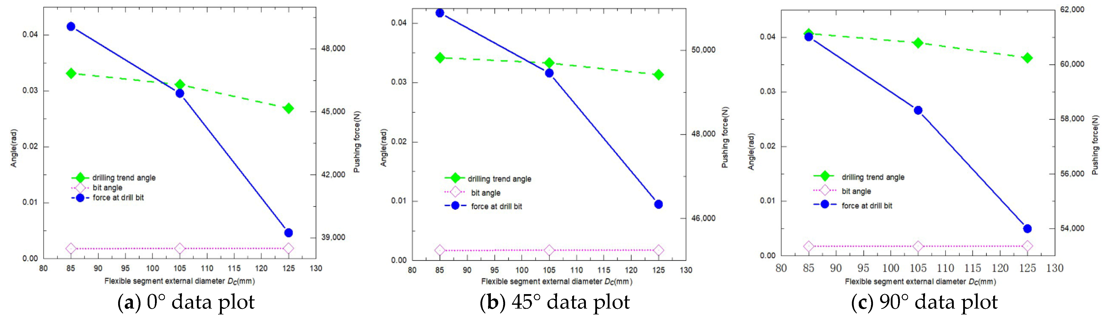
4.2. The Influence of the Outer Diameter of the Flexible Segment on Trajectory Control Ability

In order to analyze the influence of the outer diameter of the flexible segment on trajectory control ability, the length of the flexible segment is set as 1 m. Meanwhile the distance from the bit to the centralizer, the outer diameter and wall thickness of the flexible segment, the distance from the flexible segment to the paranoid mechanism, and the dis dance from the paranoid mechanism to the centralizer are set, as shown above. By keeping the flexible segment’s inner diameter unchanged and changing its outer diameter, the variation rules of drilling trend angle, the pushing force on the bit, and the rotation angle of the bit are studied. The influence of the flexible segment’s length on trajectory control ability is analyzed when the well inclination angle is 0°, 45°, and 90°, whose results are shown in Figure 7.
  • The outer diameter of the flexible segment has a greater impact on trajectory control ability. The smaller the outer diameter of the flexible segment, the greater the pushing force on the bit, the larger the bit’s rotation angle and the drilling trend angle, that is, the stronger the trajectory control ability. However, due to the consideration of the down hole safety of the flexible segment, whose outer diameter should not be too small, the optimal outer diameter is 105 mm, according to the existing data.
  • Under the premise that the outer diameter and length of the flexible segment are constant, the well inclination has a significant influence on the pushing force exerted by the new rotary steerable drilling system on the bit. With the increase in the well inclination, the pushing force on the bit shows an increasing trend and increases significantly.

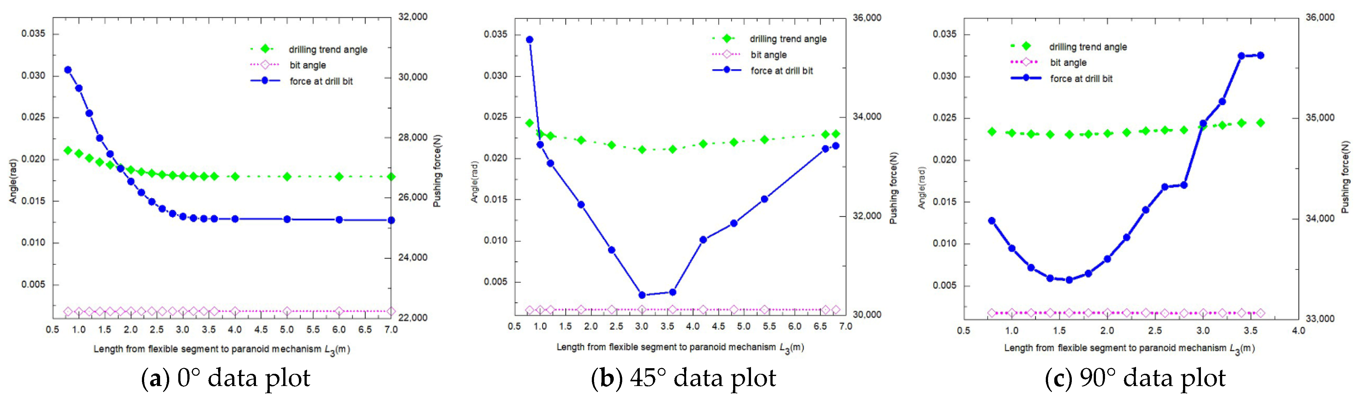
4.3. Influence of the Distance from the Flexible Segment to the Paranoid Mechanism on Trajectory Control Ability

In order to analyze the influence of the distance between the flexible segment and the paranoid mechanism on trajectory control ability, the length and the optimal outer diameter of the flexible segment are set as 1 m and 105 mm. Meanwhile, the distance from the bit to the centralizer and from the paranoid mechanism to the centralizer are set as 2.73 m. By changing the distance between the flexible segment and paranoid mechanism, the variation rules of drilling trend angle, the pushing force on the bit, and the rotation angle of the bit are studied. The influence of the distance between the flexible segment and paranoid mechanism on trajectory control ability is analyzed when the well inclination angle is 0°, 45°, and 90°, whose results are shown in Figure 8.
  • With the increase in the distance between the flexible segment and the paranoid mechanism, the change in the bit’s rotation angle is not obvious, and it can be considered that the value is basically unchanged.
  • With the increase in the distance from the flexible segment to the paranoid mechanism, the drilling trend angle and the pushing force on the bit have the same trend. At 0° inclination, both of them show a decreasing trend, while at 45° inclination and 90° inclination, both of them show a trend of first decreasing and then increasing.
  • In a well bore with an inclination angle, there is a worse distance between the flexible segment and the paranoid structure, which can weaken the trajectory control ability significantly.
  • The worse distance from the flexible segment to the paranoid mechanism tends to decrease as the well inclination increases.

4.4. Influence of the Distance from the Paranoid Mechanism to the Centralizer on Trajectory Control Ability

In order to analyze the influence of the distance from the paranoid mechanism to the centralizer on trajectory control ability, the length and the optimal outer diameter of the flexible segment are set as 1 m and 105 mm, and the distance from flexible segment to paranoid mechanism (L3) is set as 0.79 m. By changing the distance between the centralizer and paranoid mechanism, the variation rules of drilling trend angle, the pushing force on the bit, and the rotation angle of the bit are studied. The influence of the distance between the paranoid mechanism and centralizer on trajectory control ability is analyzed when the well inclination angle is 0°, 45°, and 90°, whose results are shown in Figure 9.
  • With the increase in the distance between the paranoid mechanism and the centralizer, the change in the bit’s rotation angle is not obvious, and it can be considered that the value is basically unchanged.
  • With the increase in the distance from the paranoid mechanism to the centralizer, the drilling trend angle and the pushing force on the bit have the same trend, which is to increase first and then decrease overall.
  • There is an optimal distance between the paranoid mechanism and the centralizer, which can strengthen the trajectory control ability significantly.
  • Within the set well bore, the optimal distrance from the paranoid structure to the centralizer is 2.73 m.

4.5. The Optimal Structure Scheme of the New Rotary Steerable System and the Comparison with the Existing Drilling System

The trajectory control ability of the new and the existing rotary steerable system is compared. The structure diagrams of the two steerable systems are shown in Figure 10, including Figure 10a, which shows the new rotary steerable drilling system, and Figure 10b, which shows the existing system.
The pushing force on the bit, the rotation angle, and the drilling trend angle are calculated respectively when the well inclination is 0°, 45°, and 90° and the paranoid mechanism of the two rotary steerable systems exerts the same pushing force of 1.5 tons. The details are shown in Figure 11.
  • Under the premise of the same pushing force output from the paranoid mechanism, the force obtained by the bit of the new rotary steerable system is greatly improved compared with that of the conventional rotary steerable system, and the improvement range increases with the increase in the well inclination. In the case of 0°, 45°, and 90°, the pushing force on the bit is increased by 3.7 times, 4 times, and 5.3 times respectively.
  • The inclination angle of the bit in the new rotary steerable system is a positive value, that is, it is in the same direction as the pushing force obtained by the bit, whose function is to increase the inclination. While the inclination angle of the bit in the conventional rotary steerable system is a negative value, that is, it is opposite to the direction of the pushing force obtained by the bit, whose effect is to decrease the inclination.
  • Under the premise that the paranoid mechanism outputs the same pushing force, the drilling trend angle of the new rotary steerable system is greatly improved compared with the conventional system, and the improvement range increases with the increase in the well inclination. In the case of 0°, 45°, and 90°, the drilling trend angle is increased by 5.5 times, 4.7 times, and 6.5 times, respectively.
  • The pushing force obtained by the bit in the new rotary steerable system is in the same direction as the inclination angle of the bit, and the two control the borehole trajectory together. Meanwhile the pushing force on the bit in the conventional rotary steerable system is opposite to the direction of the inclination angle of the bit, that is, the trajectory control process and the two effects are contradictory. The performance of the trajectory control depends on who is dominant.
  • The direct factor for the change in the borehole trajectory is the bit. Whether the bit can cut the sidewall is the fundamental factor for the trajectory change in push-the-bit rotary steerable drilling. Therefore, no matter which steerable mode, it is necessary to carry out research on matching bits to optimize the effect [20].

5. Discussion

This study only focuses on the pushing force on the bit and pointing angle of the bit (including drilling trend angle). However, the direct factor of well bore trajectory change is the bit. The research on matching the bit should be carried out regardless of any steerable method in order to achieve optimal effect.
The above study provides new technical ideas for solving the problems of improving the trajectory control ability, prolonging the tool’s life, and increasing the drilling speed of rotary steerable drilling technology. The study also provides a reference for the research and development of a new rotary steerable drilling system. However, the present study is only in the initial stage. The trajectory control effect under the combined action of WOB, bit, and formation needs further in-depth research and field verification and optimization.

6. Conclusions

The trajectory control ability of the new rotary steerable system based on the principle of a “labor-saving lever” is affected by the distance from the bit to the centralizer, the structural parameters of the flexible segment, the distance from the flexible segment to the paranoid mechanism, and the distance from the paranoid mechanism to the centralizer. Reducing the stiffness of the flexible segment, shortening the distance from the flexible segment to the paranoid mechanism, and optimizing the distance from the paranoid mechanism to the centralizer are the keys to improve the trajectory control ability of the new rotary steerable method to the utmost.
Compared with the conventional steerable system, the new one achieves 3.7, 4, and 5.3 times more pushing force on the bit when the pushing force output by the tool is the same at a well inclination of 0°, 45°, and 90°. Meanwhile, the drilling trend angle is increased by 5.5 times, 4.7 times, and 6.5 times, respectively, and the pushing force on the bit in the new rotary steerable system is in the same direction as the inclination angle of the bit, both of which work together to control the borehole trajectory. It overcomes the shortcomings of a conventional rotary steerable system such that the pushing force on the bit and the inclination angle of the bit are opposite, and the two effects are contradictory, thus limiting the trajectory control ability.

Author Contributions

Writing—original draft preparation, Y.L., X.Q., J.J. and G.L.; Writing—review and editing, Y.L. and X.Q. All authors have read and agreed to the published version of the manuscript.

Funding

The National Natural Science Foundation of China’s general project “The Influence Law and Regulation Mechanism of Oil and Gas Wellbore Pipe Load on its Sound Transmission” (No. 52074324); The National Natural Science Foundation’s general project “The Mechanism and Control Criterion of Hard and Thick Roof Breaking Based on Thick Plate Theory” (No. 51674284); The national key R&D program, the intergovernmental key project of international scientific and technological innovation cooperation, “Speed-up Technology of Ultra-high Pressure Jet Coupled with Mechanical Impact in Deep geothermal well drilling” (No. 2021YEE0111400).

Institutional Review Board Statement

Not applicable.

Informed Consent Statement

Not applicable.

Data Availability Statement

Not applicable.

Acknowledgments

This work was supported by the Strategic Pilot Science and Technology Project of Chinese Academy of Sciences (XDA14030000), the Key Projects of China National Offshore Oil Corporation (CNOOC-KJ135ZDXM25ZHYF-1), and the Shandong Key Research and Development Program (International Science and Technology Cooperation, 2019GHZ001).

Conflicts of Interest

The authors declare no conflict of interest.

References

  1. Qilong, X.; Qingshan, D.; Leilei, H. The latest progress and development trend of rotary steering drilling technology. China Pet. Mach. 2010, 41, 1–6. [Google Scholar]
  2. Bayliss, M.T.; Panchal, N.; Whidborne, J.F. Rotary steerable directional drilling stick/slip mitigation control. IFAC Proc. Vol. 2012, 45, 66–71. [Google Scholar] [CrossRef]
  3. Xinjun, G.; Jing, L. Research on application of steering drilling technologies in shale gas development. Procedia Eng. 2014, 73, 269–275. [Google Scholar] [CrossRef]
  4. Staff, J. Hybrid rotary steerable system delivers higher build rates and smoother holes. J. Pet. Technol. 2013, 65, 32–34. [Google Scholar] [CrossRef]
  5. Matheus, J.; Ignova, M.; Hornblower, P. A hybrid approach to closed-loop directional drilling control using rotary steerable systems. In Proceedings of the SPE Latin America and Caribbean Petroleum Engineering Conference, Maracaibo, Venezuela, 21–23 May 2014; OnePetro: Richardson, TX, USA, 2014. [Google Scholar]
  6. Chunxu, Y.; Ruihe, W.; Laiju, H. A dynamic evaluation method for safe operation of the bottom hole assembly with bit-push rotary steering drilling system. Mech. Sci. 2020, 44, 64–70. [Google Scholar]
  7. Xiong, J.; Wen, J.; Rong, J. New progress in research on rotational oriented drilling technology. Nat. Gas Ind. 2010, 30, 87–90. [Google Scholar]
  8. Zhipeng, C.; Xing, L.; Gaocheng, W.; Yajun, J.; Jiehui, Z.; Zhaofeng, L. Application of rotary geosteering technology in horizontal wells and its implication: A case study of the zhaotong shale gas demonstration area of Yunnan. Nat. Gas Ind. 2015, 35, 64–70. [Google Scholar]
  9. Wei, J.; Shiquan, J.; Limin, S. Research on rotary navigation drilling tools and its application. Oil Drill. Prod. Technol. 2008, 30, 21–24. [Google Scholar]
  10. Tetsuo, Y.; Cargill, E.J.; Gaynor, T.M.; Hardin, J.; Hay, R.T.; Akio, I.; Kiyosawa, Y. Robotic controlled drilling: A new rotary steerable drilling system for the oil and gas industry. In Proceedings of the IADC/SPE Drilling Conference, Dallas, TX, USA, 26–28 February 2002. [Google Scholar]
  11. Flatern, R.V. Rotary steerables ready for the mainstream. Offshore Eng. 2003, 28, 32–36. [Google Scholar]
  12. Zhirui, W.; Junliang, W. Development of rotary steering technology in foreign countries and its status quo in china. Drill. Prod. Technol. 2018, 41, 5. [Google Scholar]
  13. Yucai, S.; Haifang, S.; Bujiang, Y.; Zhichuan, G.; Heng, W.; Zaiqing, M. A design method to prevent self-locking of a static push-the-bit rotary steerable drilling tool. J. China Univ. Pet. (Ed. Nat. Sci.) 2017, 41, 7. [Google Scholar]
  14. Jinzhou, Z.; Mingxin, S. Analysis of working mode of rotary steerable drilling system. China Pet. Mach. 2004, 32, 3. [Google Scholar]
  15. Qi, L.; Chun-wen, D.; Shao-huai, Z. Well trajectory control theory for rotary steering drilling system and applied techniques. Acta Pet. Sin. 2005, 26, 5. [Google Scholar]
  16. Shihong, X.; Zheng, L. Development status and prospect of rotary guided drilling technology. China Pet. Mach. 2006, 34, 5. [Google Scholar]
  17. Jing, L.; Gansheng, Y.; Tao, L. Steering principles of rotary steerable drilling systems in china and abroad. Explor. Eng. (Rock Soil Drill. Tunn.) 2012, 39, 53–58. [Google Scholar]
  18. Yongwang, L. An Efficient Intelligent Steering Drilling System and Drilling Method. 2020. [Google Scholar]
  19. Yucai, S.; Zhichuan, G.; Hongshan, Z.; Genlu, H. A new method for build-up rate prediction of bottom-hole assembly in well drilling. J. China Univ. Pet. (Ed. Nat. Sci.) 2015, 41, 85–89. [Google Scholar]
  20. Yongwang, L.; Yong, H.; Deyong, Z.; Zhichuan, G.; Yuca, S. A High Build Slope Bit Suitable for Push against Rotary Steering Drilling Technology. 2021. [Google Scholar]
Figure 1. Schematic diagram of the new rotary steerable drilling system.
Processes 10 01621 g001
Figure 2. Schematic diagram of the steerable process of the new rotary steerable drilling system.
Processes 10 01621 g002
Figure 3. Model simplification and unit division.
Processes 10 01621 g003
Figure 4. Schematic diagram of the new rotary steerable drilling system.
Processes 10 01621 g004
Figure 5. Digram of drilling trend angle.
Processes 10 01621 g005
Figure 6. Influence of the flexible segment length (L4) on trajectory control capacity of the tool.
Processes 10 01621 g006
Figure 7. Influence of the flexible segment external diameter (DC) on trajectory control capacity of the tool.
Processes 10 01621 g007
Figure 8. Influence of the length from the flexible segment to the paranoid mechanism (L3) on trajectory control capacity.
Processes 10 01621 g008
Figure 9. Influence of the length from paranoid mechanism to centralizer (L2) on trajectory control capacity of the tool.
Processes 10 01621 g009
Figure 10. Structure comparison of rotary steerable drilling system.
Processes 10 01621 g010
Figure 11. Comparison of trajectory control ability of two kinds of steerable systems.
Processes 10 01621 g011
Publisher’s Note: MDPI stays neutral with regard to jurisdictional claims in published maps and institutional affiliations.

