
Study on the Influence of Flow Distribution Structure of Piston Pump on the Output of Pulsation Pump

Abstract
:1. Introduction
2. Working Principle of Valve Plate of Axial Piston Pump
3. Analysis of Output Flow Pulsation of Axial Piston Pump
3.1. Analysis of Output Flow Pulsation of Axial Piston Pump under Constant Working Conditions
3.2. Analysis of Output Flow Pulsation of an Axial Piston Pump in Practical Situation
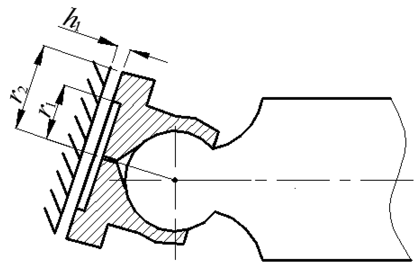
3.2.1. Analysis of Oil Leakage in a Plunger Pump
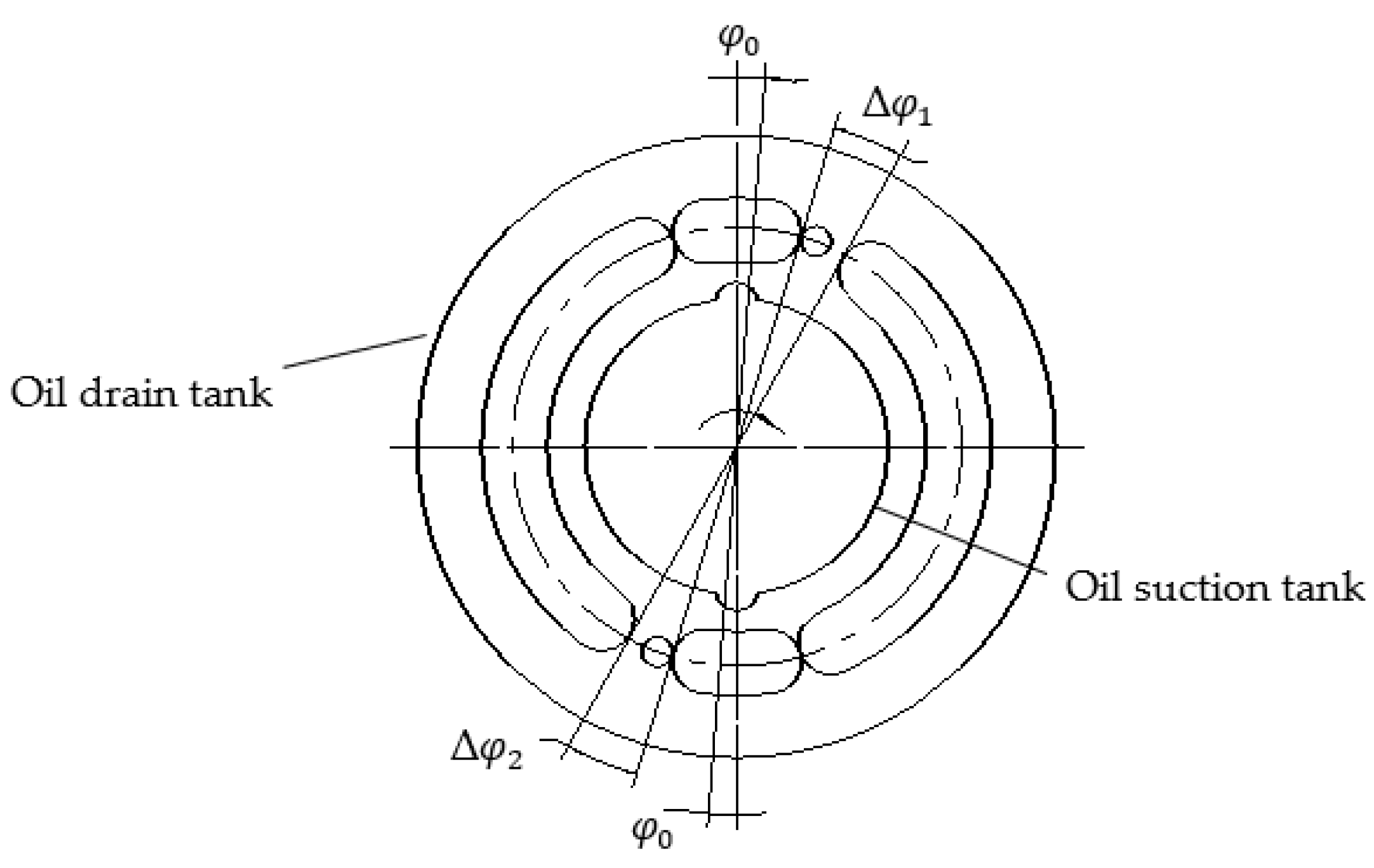
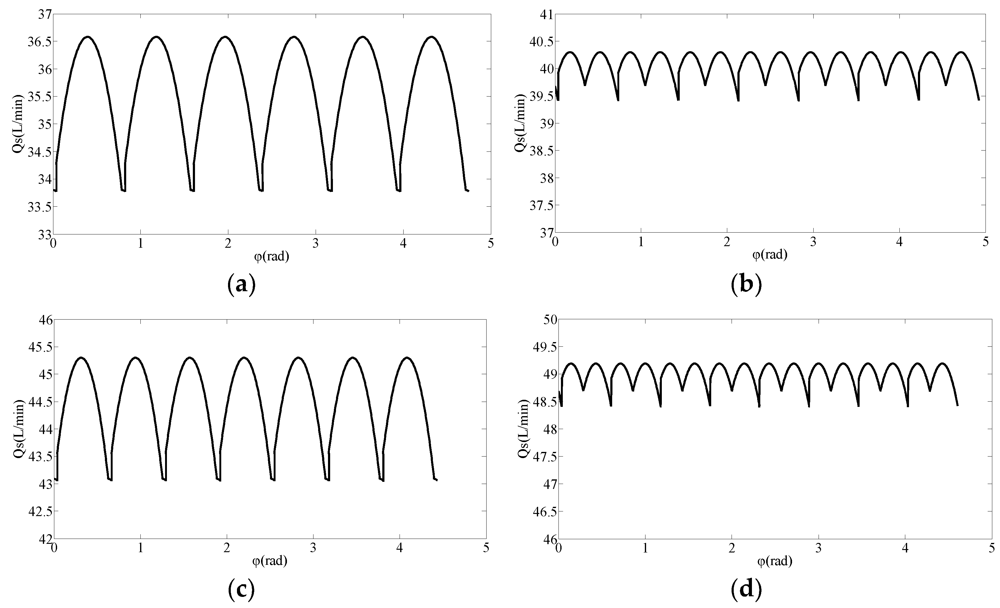
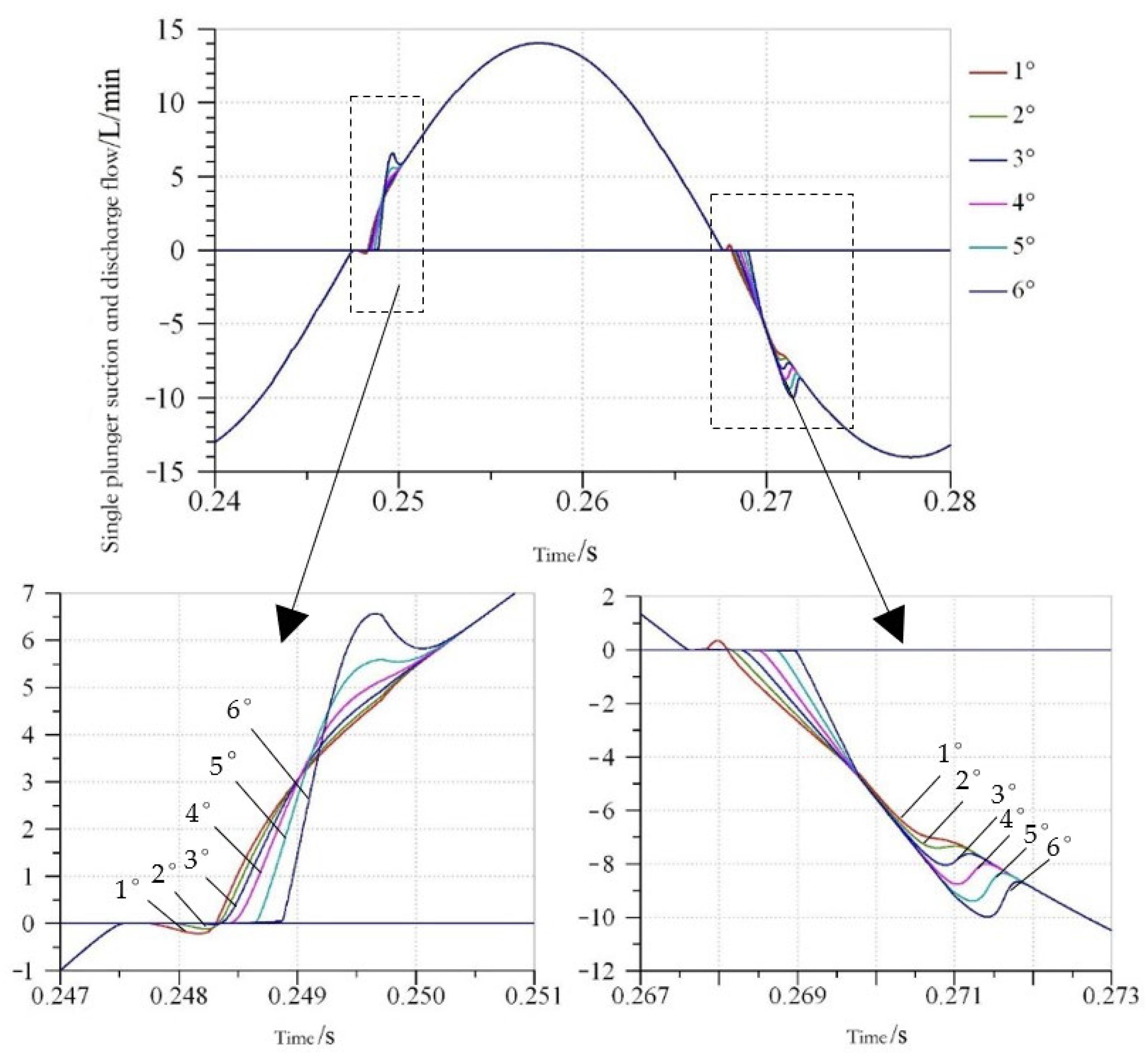
3.2.2. Influence of Port Plate Structure on Output Flow Pulsation of Axial Piston Pump
- (1)
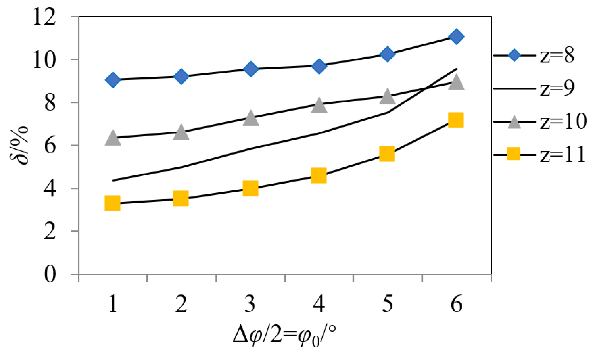
- Δφ/2 = = 6°, δz = 11 < δz = 10 < δz = 9 < δz = 8, that is, the larger the number of plungers, the smaller the pump output flow pulsation rate. The flow pulsation rate values are greater than the theoretical instantaneous flow pulsation rate, but the regularity is consistent with it. However, when Δφ/2 = = 1~5°, δz = 11 < δz = 9 < δz = 10 < δz = 8, that is, the output flow pulsation of odd pump is obviously less than that of even pump.
- (2)
- When Δφ/2 = decreases from 6° to 1°, the output flow curves of 8~11-piston pumps become more and more regular, the flow pulsation rate decreases gradually, the flow pulsation of odd number pump decreases faster than that of even number pump and the gap between them becomes larger and larger.
- (3)
- When Δφ/2 = = 1°, the flow pulsation rate of 8~11-plunger pumps reaches the minimum value, which is close to the theoretical value. When Δφ/2 = = 3°, the fluctuation of the difference of the pump flow pulsation rate of the number of adjacent plungers is the smallest. When Δφ/2 = = 5~6°, the flow pulsation rates of 9- and 10-plunger pumps are very close. Under this port plate structure, the number of plungers is designed as 9 or 10, which breaks the convention that odd piston pumps are better than even piston pumps.
4. System Modeling and Simulation Analysis of Axial Piston Pump
4.1. Modeling and Correctness Verification
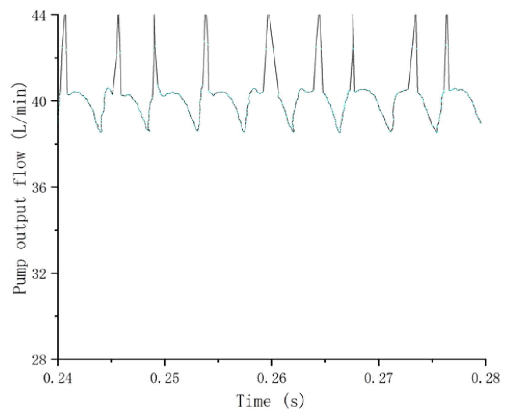
4.2. Simulation Analysis of Influence of Port Plate Structure on Output Flow Pulsation of Axial Piston Pump
5. Experimental Verification
6. Conclusions
- (1)
- Without considering leakage and flow distribution, the output flow pulsation rate of an odd pump is obviously lower than that of an even pump. With the increase of the number of plungers, the pump output flow pulsation rate decreases. The larger the number of plungers, the slower the decreasing trend of flow pulsation.
- (2)
- The influence of the port plate structure on pump output flow pulsation under different flow distribution conditions was studied. It is more reasonable when the mismatching angle of the valve plate is 3~5° and the dead angle is 6~10°. At this time, the difference between the output flow pulsation of odd and even piston pumps is very small, and the odd or adjacent even number of pistons is appropriate. In the hydraulic pump hydraulic motor system, when the hydraulic pump is used as a hydraulic motor under the condition of power recovery, the odd number or adjacent even number of hydraulic motors are appropriate.
- (3)
- Through the comparison of the prototype pump bench test and simulation data, the correctness of the simulation conclusion was verified, which provides a reference for the design and improvement of the piston pump.
Author Contributions
Funding
Acknowledgments
Conflicts of Interest
References
- Pan, Y.; Li, Y.B. Valve Plate Improvement and Flow Ripple Characteristic Analysis for Double Compound Axial Piston Pump. Trans. Chin. Soc. Agric. Mach. 2016, 47, 391–398. [Google Scholar]
- Hu, M.; Xu, N. Modelling and Analysis of Dynamics Characteristics of Piston-slipper Group of Axial Piston Pump. Trans. Chin. Soc. Agric. Mach. 2016, 47, 373–380. [Google Scholar]
- Zhang, X.G.; Yan, Z.; Quan, L. Theoretical Analysis and Experiment on Flow Allocation Characteristics of Dual Discharging Axial Piston Pump. Trans. Chin. Soc. Agric. Mach. 2017, 48, 373–380. [Google Scholar]
- Zhang, Z.P. Design and Research of 55 mL/R Eleven Plunger Swashplate Axial Piston Pump. Master’s Thesis, Southwest Jiao Tong University, Chengdu, China, 2009. [Google Scholar]
- Yuan, H. Structural Optimization Design of Key Parts of Swashplate Axial Piston Pump. Master’s Thesis, Hefei Polytechnic University, Hefei, China, 2015. [Google Scholar]
- Wang, H.Y.; Wei, X.Y. Simulation Study on the Flow Pulsation Characteristics of Axial Piston Pump. Mach. Tool Hydraul. 2014, 42, 144–148. [Google Scholar]
- Ye, M. Theoretical analysis of flow pulsation of axial piston pump. Trans. Chin. Soc. Agric. Mach. 1990, 19, 41–47. [Google Scholar]
- Na, Y.Q.; Yin, W.B.; Na, C.L. Theretical Analysis of Transit Flow Through Axial Piston Pumps. J. Lanzhou Univ. Technol. 2004, 30, 56–59. [Google Scholar]
- Liu, C.J.; Xu, X.L. Simulation analysis of actual flow in axial piston pump. Mach. Tool Hydraul. 1999, 3, 66–67. [Google Scholar]
- Yan, Y.Q.; Shi, Z.Q.; Zheng, L. Analysis of Influence Factors for Axial Piston Hydraulic Pump Flow Fluctuation Based on AMESim. Chin. Hydraul. Pnenumatics 2014, 2, 104–108. [Google Scholar]
- Zhang, R.; Liu, H.L.; Ke, J. Characteristics Simulation of Swashplate Axial Piston Pump Based on AMESim. Mach. Tool Hydraul. 2012, 40, 118–120. [Google Scholar]
- Harrisona, M.; Edge, K.A. Proceedings of the Institution of Mechanical Engineers; Institution of Mechanical Engineers: London, UK, 2000; Volume 214, pp. 53–64. [Google Scholar]
- Weddfelt, K.G.; Pettersson, M.E.; Palmberg, J. Methods of Reducing Flow Ripple from Fluid Power Piston Pumps-an Experimental Approach. Phys. Status Solidi Appl. Res. 1991, 73, 71–79. [Google Scholar]
- Liu, Z.F.; Yuan, H.; Cheng, H.B. Method for Determining Best Piston Numbers of a Swash Plate Axial Piston Pump. China Mech. Eng. 2015, 26, 237–242. [Google Scholar]
- Bergada, J.M.; Kumar, S.; Davies, D.L.; Watton, J. A complete analysis of axial piston pump leakage and output flow ripples. Appl. Math. Model. 2012, 36, 1731–1751. [Google Scholar] [CrossRef]
- Bergada, J.M.; Watton, J.; Haynes, J.M.; Davies, D.L. The hydrostatic/hydrodynamic behaviour of an axial piston pump slipper with multiple lands. Meccanica 2010, 45, 585–602. [Google Scholar] [CrossRef] [Green Version]
- Bergada, J.M.; Davies, D.L.; Kumar, S.; Watton, J. The effect of oil pressure and temperature on barrel film thickness and barrel dynamics of an axial piston pump. Meccanica 2012, 47, 639–654. [Google Scholar] [CrossRef]
- Zhu, H.; Bo, G.; Zhou, Y.B. Pump Selection and Performance Prediction for the Technical Innovation of an Axial-Flow Pump Station. Math. Probl. Eng. 2018, 2018, 6543109. [Google Scholar] [CrossRef]
- Zhang, T.X.; Zhang, N. Vibration Modes and the Dynamic Behaviour of a Hydraulic Plunger Pump. Shock. Vib. 2016, 2016, 9679542. [Google Scholar] [CrossRef] [Green Version]
- Ji, D.T.; Lu, W.G.; Lu, L.G. Comparison of Saddle-Shaped Region of Head-Flow Curve between Axial-Flow Pump and Its Corresponding Axial-Flow Pump Device. Shock. Vib. 2021, 2021, 9481822. [Google Scholar] [CrossRef]
- Lasaar, R. The influence of the microscopic and macroscopic gap geometry on the energy dissipation in the lubricating gaps of displacement machines. In Proceedings of the 1st FPNI-PhD Symposium, Hamburg, Germany, 20–22 September 2000; Volume 9, pp. 101–116. [Google Scholar]
- Lasaar, R.; Ivantysynova, M. Advanced gap design-basis for innovative displacement machines. In Proceedings of the 3rd International Fluid Power Conference, Aachen, Germany, 5–6 March 2002; Volume 2, pp. 215–230. [Google Scholar]
- Olems, L. Investigations of the temperature behaviour of the piston cylinder assembly in axial piston pumps. Int. J. Fluid Power 2000, 1, 27–39. [Google Scholar] [CrossRef]
- Park, S.H.; Lee, J.M.; Kim, J.S. Robust control of the pressure in a control-cylinder with direct drive valve for the variable displacement axial piston pump. Proc. Inst. Mech. Eng. Part I J. Syst. Control Eng. 2009, 223, 455–465. [Google Scholar] [CrossRef]
- Zhang, X.J.; Chen, Y.H.; Zhou, Z.J. Influence of Axial Piston Pump Parameters to Flow and Pressure Pulsation. Mach. Tool Hydraul. 2018, 46, 125–129. [Google Scholar]
- Zhang, J.; Liu, B.L.; Lv, R.Q.; Yang, Q.F.; Dai, Q.M. Study on Oil Film Characteristics of Piston-Cylinder Pair of Ultra-High Pressure Axial Piston Pump. Processes 2020, 8, 68. [Google Scholar] [CrossRef] [Green Version]
- Deng, H.S.; Wang, Q.C.; Dai, P.; Yang, Y.K. Study on Leaking Characteristics of Port Plate Pair in Primary Three-Row Axial Piston Pump/Motor. Math. Probl. Eng. 2018, 2018, 7395727. [Google Scholar] [CrossRef] [Green Version]
- Hong, H.C.; Zhao, C.X.; Zhang, B.; Bai, D.P.; Yang, H.Y. Flow Ripple Reduction of Axial-Piston Pump by Structure Optimizing of Outlet Triangular Damping Groove. Processes 2020, 8, 1664. [Google Scholar] [CrossRef]
- Huang, Y.; Ruan, J.; Zhang, C.C.; Ding, C.; Li, S. Research on the Mechanical Efficiency of High-Speed 2D Piston Pumps. Processes 2020, 8, 853. [Google Scholar] [CrossRef]
- Gao, Y.J.; Gu, L.C.; Jiao, L.F. Effects of Oil Properties on Flow Pulsation of Axial Piston Pumps by Simulation Analysis. China Mech. Eng. 2017, 28, 1333–1338. [Google Scholar]


| Z is an odd number | 5 | 7 | 9 | 11 | Z is an even number | 6 | 8 | 10 | 12 |
| Pulsation rate δ1/% | 4.97 | 2.52 | 1.53 | 1.02 | Pulsation rate δ1/% | 14.03 | 7.66 | 4.97 | 3.45 |
| Name | Numerical Value | Unit |
|---|---|---|
| Radius of plunger distribution circle | 29.7 | mm |
| Prime mover speed | 1500 | r/min |
| Plunger diameter | 17 | mm |
| Inclined plate | 12.5 | degree |
| Contact length between plunger and cylinder block | 34.6 | mm |
| Viscous damping coefficient | 5 | Nm (rev/min) |
| Coulomb friction torque loss | 3 | Nm |
| Static friction torque loss | 7 | Nm |
| Plunger pair fit clearance | 0.005 | mm |
| Shoe pair clearance | 0.002 | mm |
| Clearance of port pair | 0.01 | mm |
| Moment of inertia of cylinder block | 0.0016 | Kgmm2 |
| Initial tank pressure | 2 | bar |
| Maximum opening diameter of oil drain throttle valve | 2.9 | mm |
| Maximum opening diameter of oil suction throttle valve | 4.3 | mm |
| Name | Simulation Value | Experimental Value |
|---|---|---|
| 9 plunger pump | 6.56 | 7.45 |
| 10 plunger pump | 7.91 | 8.65 |
Publisher’s Note: MDPI stays neutral with regard to jurisdictional claims in published maps and institutional affiliations. |
© 2022 by the authors. Licensee MDPI, Basel, Switzerland. This article is an open access article distributed under the terms and conditions of the Creative Commons Attribution (CC BY) license (https://creativecommons.org/licenses/by/4.0/).
Share and Cite
Li, R.; Liu, J.; Ding, X.; Liu, Q. Study on the Influence of Flow Distribution Structure of Piston Pump on the Output of Pulsation Pump. Processes 2022, 10, 1077. https://doi.org/10.3390/pr10061077
Li R, Liu J, Ding X, Liu Q. Study on the Influence of Flow Distribution Structure of Piston Pump on the Output of Pulsation Pump. Processes. 2022; 10(6):1077. https://doi.org/10.3390/pr10061077
Chicago/Turabian StyleLi, Ruichuan, Jilu Liu, Xinkai Ding, and Qi Liu. 2022. "Study on the Influence of Flow Distribution Structure of Piston Pump on the Output of Pulsation Pump" Processes 10, no. 6: 1077. https://doi.org/10.3390/pr10061077