1. Introduction
Rotary drums are used in many industries such as chemical, pharmaceutical, metallurgical, and food processing [
1]. They provide good conditions for mixing, drying, coating, granulation, chemical reaction [
2], clinkering of cement, regeneration of spent catalyst, and char activation [
3]. They can process a wide range of particle sizes and shapes. High construction cost, non-uniform temperature profile, and limited reaction rate between solid and gas are their disadvantages [
3].
Rotary drums can be used in batch or continuous processes [
4]. In continuous mode, solids are fed into the drum through a feeder. They move forward and mix by a combined action of rotation and gravitation due to inclination of the drum. The time that particles stay in the drum is defined as residence time [
5]. Residence time is one of the most important parameters that can be used to evaluate heat and mass transfer conditions and reaction extent in the rotary drum [
6]. For instance, if heat transfer derives the drying or reaction of particles, the residence time of particles must be longer than time that is required to accomplish desired drying or reaction [
7]. Thus, residence time distribution (RTD) can affect the reaction progress or the pyrolysis performance in the kiln [
8].
Plug flow and completely mixed flow are two different ideal models for flow patterns. In reality, solid flow differs from these ideal flow models. Thus, the RTD of particles deviates from the RTD of plug flow and mixed flow [
9]. Many factors affect the RTD, such as the rotation speed of the drum, incline angle, feed rate (as operation variables) [
10,
11], internal geometry [
12], and particle shape [
13].
Most of the studies on the RTD measurement in rotary drums are dedicated to spherical particles as reviewed, e.g., by Lu et al. [
14], while in industrial application, particles are mostly non-spherical [
15,
16]. Some other researchers study non-spherical shape in rotary drums via the means of experiments and simulation, such as cylindrical particles (such as broken rice or wood pellet) [
10,
11,
17,
18], cuboid particles (such as wood chips or alumina) [
5,
15,
17,
19], pharmaceutical tablets [
1], ellipsoid particles [
20], polyhedral particles [
21], and cubic particles [
16,
18]. In addition, even spherical particles may undergo shape change due to cohesion, breakage, or reaction [
7,
22]. Non-spherical particles’ flow behavior is more complex than spherical particles [
23]. For instance, correlations and criteria used for characterizing flow regime for spherical particles may not be used for non-spherical particles [
2,
20,
24].
The axial dispersion model (ADM) is used to describe non-ideal solid flow [
25]. RTD of solids can be defined as a function of Peclet number. Peclet number includes the combined effect of dispersion coefficient and mean residence time (MRT). Thus, a change in the axial dispersion coefficient or the MRT can lead to a change in the RTD. Variables in the ADM are meaningful and can be compared to other phenomena such as reaction and heat transfer [
16,
25]. Gao et al. measured RTD of spherical, cylindrical and quadrilobe particles. Their results showed that non-spherical particles have less axial dispersion than spheres [
5]. Lu et al. studied axial dispersion coefficient for cubic particles. Their results showed that axial dispersion coefficient depends on rotation speed, acceleration of gravity and volume equivalent diameter [
16].
In addition to experiments, discrete element (DEM) simulations answer many unknowns concerning granular flow through accurate modeling of inter-particle interactions. DEM is a robust and mature modeling approach for granular flow. The sub-models of mechanical contact interactions and techniques for representing particle surface are well established for spherical particles, while sub-models and shape representations of non-spherical particles still need improvement [
26]. One fundamental step in utilizing DEM for granular flow is to validate simulation results against reliable experimental measurements. Therefore, providing detailed and vast experimental data on the flow behavior of granular flows (especially for non-spherical particles) for DEM-based research is another aim of this research.
Among non-spherical particle with regular and irregular shape, cubic and cuboid particles can be obtained by six cuts, and their dimensions can be easily specified. Thus, we used cubic particles as the model particle for non-spherical particles with sharp edges. Additionally, wooden and ceramic cuboid particles were used in a mixture to find the effect of density variation. This mixture resembles the conditions that the solid flow contains particles with various density (such as wood pyrolysis in rotary kiln with ceramic as a heat carrier [
27]). RTD was measured at different rotation speeds, incline angles, feed rates, particle sizes, and volume fraction of wooden particles, and then fitted to the ADM. In all cases, we tried to compare our results with similar results on spherical and non-spherical particles without sharp edge to find the similarities and the differences between their flow behavior. All the experimental results on RTD were also provided as
Supplementary Data to be used by other researchers who are aiming to validate their DEM simulation results.
2. Material and Procedure
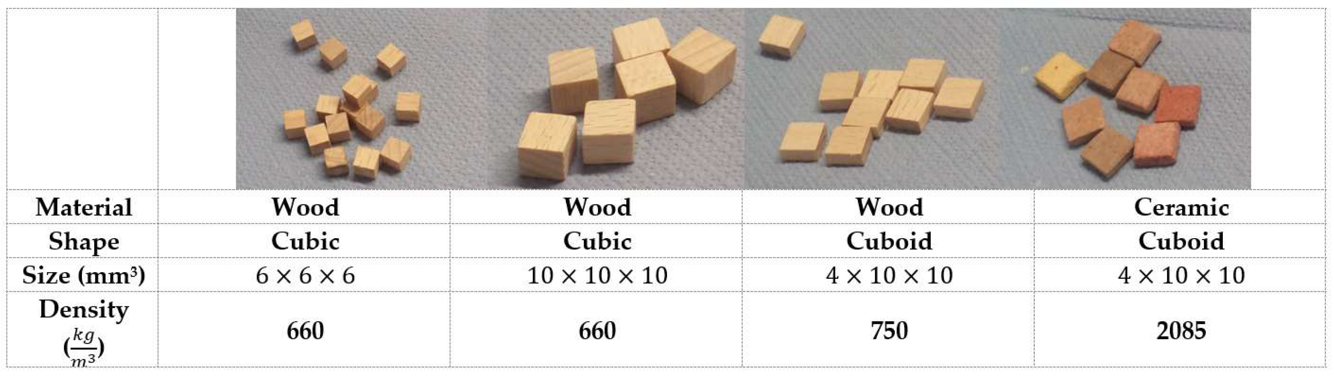
Figure 1 shows the shape and properties of particles that we used in this study. The dimensions of cubic wooden particles were 6 × 6 × 6 mm
3 and 10 × 10 × 10 mm
3. We also tested the variation in the density with cuboid ceramic (heavy) and wooden (light) particles whose dimensions were 4 × 10 × 10 mm
3. The density variation is important, since, in reality, ceramic particles can be used as heat carriers in the system [
27].
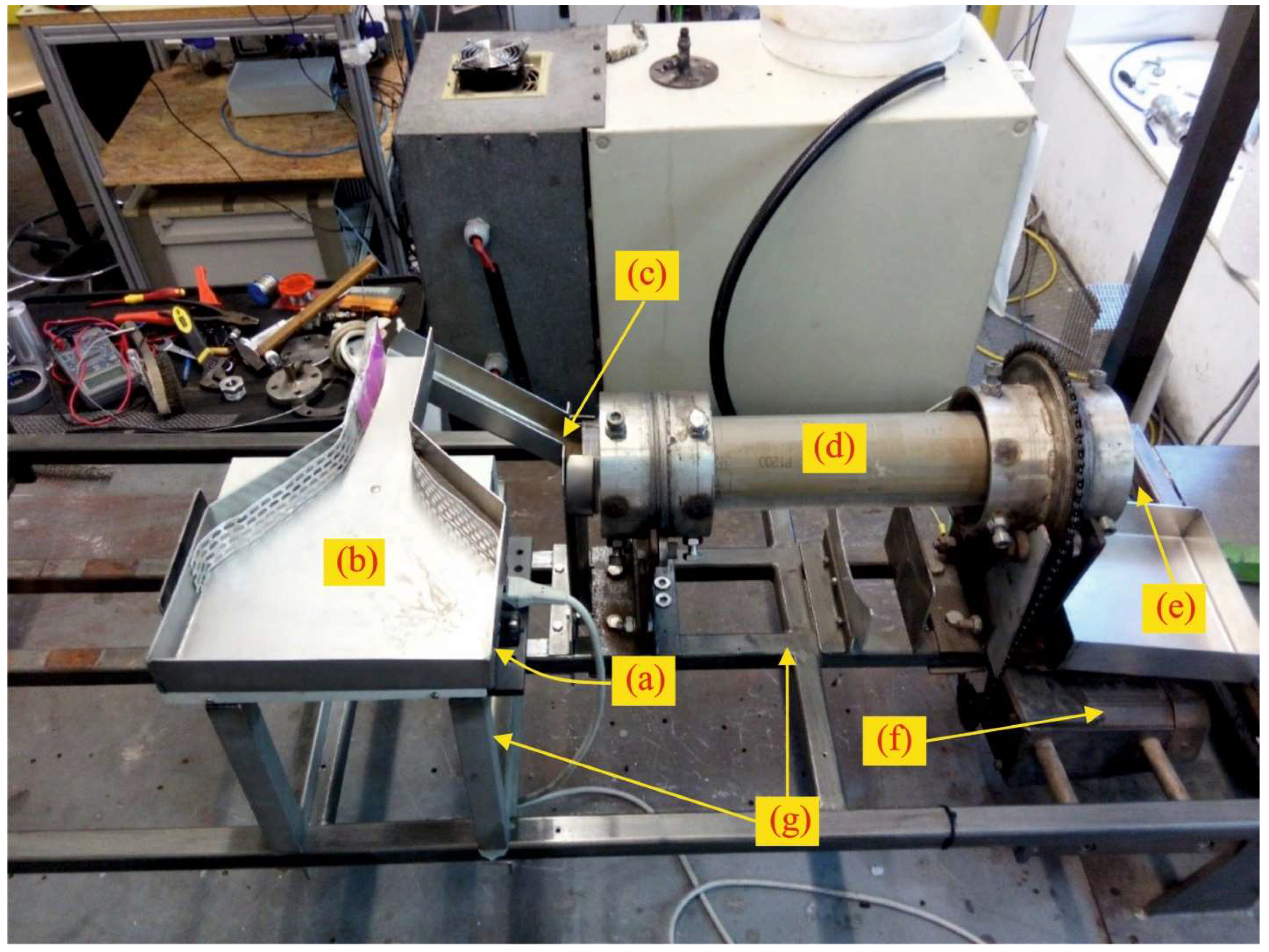
All experiments were performed in a rotary drum with length 50.0 cm, inside diameter 8.4 cm, and outside diameter 9.0 cm and at room temperature. The drum was made of plexiglas with very smooth surface. This smooth surface could not resemble the actual roughness of the rotary kilns in practice. Therefore, a thin sandpaper P1200 was affixed to the inside surface of the drum to achieve the desirable roughness in the surface.
Figure 2 shows the experimental setup including parts that were used in this research.
A three-phase AC motor (400 V) was used with a frequency inverter for rotation speed control. The feeder was vibrated using a Retsch DR 100 vibrator (Retsch, Hann, Germany) to achieve the desired flow rate of particles. The incline angle of the support of the kiln was changed by a jack.
Table 1 lists experimental conditions. Rotation speed varied between 3 rpm to 11 rpm; incline angle, between 2° to 4°; and feed rate, between 0.67 cm
3/s and 1.08 cm
3/s for cubic particles. Cuboid particles (wood and ceramic mixture) were used to determine the effect of density at 7 rpm and 2°, whereas the volume fraction of wood was varied in the mixture of wood and ceramic particles.
We used colored particles as the tracers. When rotary drum operation reached steady state condition, these colored tracers were fed into the drum. A Samsung HMX-F90 camera, located near the outlet of drum, recorded the particles’ movement and their exit moments. Entrance and exit times of each tracer give us the residence time. Recorded videos were processed by Kdenlive 19.12.3. Each experiment was repeated three times.
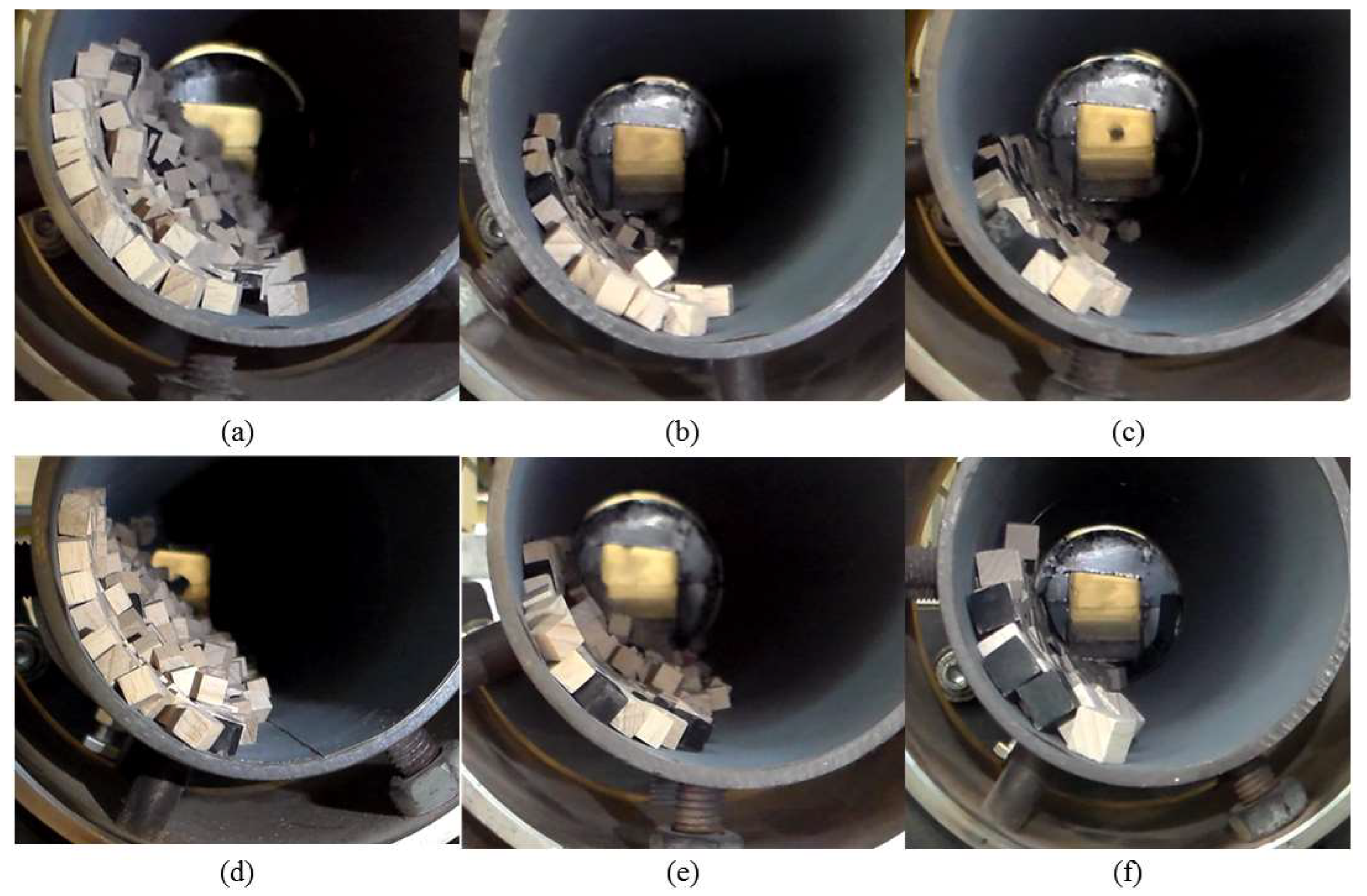
Figure 3 demonstrates cross view of drum at different rotation speed, incline angle and feed rate for 6 mm and 10 mm cubes. Tracers are particles with dark color.
4. The Axial Dispersion Model (ADM)
A one-dimensional axial dispersion model (ADM) was used for fitting experimental data. This model describes convective-dispersive transport of particles at unsteady state condition without reaction [
28,
29].
where
C(
z,
t) shows dimensionless tracer concentration,
z is dimensionless length (
z = l/
L),
l is position of tracer in the axial direction,
t is time,
uz is the mean axial velocity,
L is the drum length, and
Pe is the Peclet number.
Pe number indicates the ratio of convective mass transport to dispersive mass transport. If the
Pe number is high, the convective mass transport is dominant; while if
Pe number is low, the dispersion is dominant. A narrow time distribution is obtained when
Pe number is high, while a wide distribution is obtained when
Pe number is low.
where
Dax is axial dispersion coefficient
, as a measure for erratic movement [
10].
All dispersion is assumed to happen in the drum; which means that the tracer concentration gradient begins from the drum inlet by dispersion and convection (Equation (5)) and ends at the drum outlet (Equation (6)) [
28,
29].
ADM equation with above boundary conditions is solved numerically [
28,
29], though the analytical solution can be found for
Pe > 50 [
30]. An implicit finite difference method was used to solve ADM according to the above boundary conditions. Solution of ADM gives the tracer concentration at all positions and times.
C(
z = 1,
t) shows the concentration of tracer at the drum outlet that depends on
Pe. Time distribution changes due to changes in
Pe. Average absolute square error (AASE) was defined (Equation (7)), to find the best fitted curve of ADM on experimental data. The nearest curve is obtained based on the minimum value of AASE. MRT is obtained from the experiment based on Equation (2). Consequently, the axial dispersion coefficient is calculated by Equation (4). fminbnd function is used in MATLAB R2018b to minimize AASE.
5. Result and Discussion
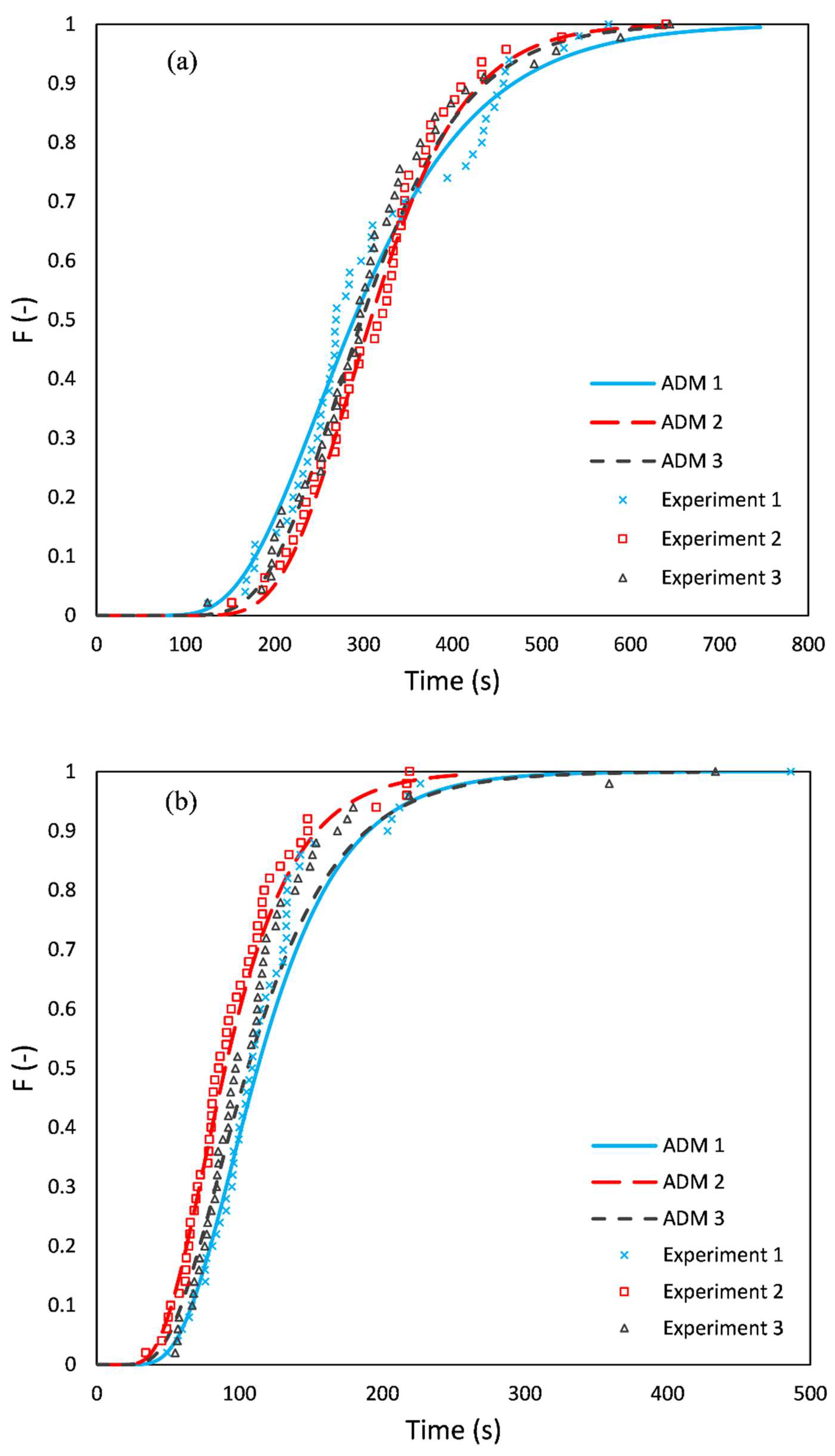
Figure 5 shows the cumulative residence time distributions obtained from experiments and fitted with the ADM. The cumulative residence time distribution,
F(
t), shows the fraction of tracers that has left the drum. It includes RTD results of three rotation speeds (3, 7, and 11 rpm), three incline angles (2, 3 and 4°), and two feed rates (0.67 and 1.08 cm
3/s) for 6 mm cubes. The ADM fitted curves can describe one-dimensional flow behavior in the drum very well. The difference between the first and the last tracer residence time for 3 rpm (
Figure 5a) is approximately 550 s. For the two other cases (7 rpm and 11 rpm), these differences are approximately 300 s and 80 s; therefore, when rotation speed increases, tracers leave the drum faster, and RTD becomes narrower.
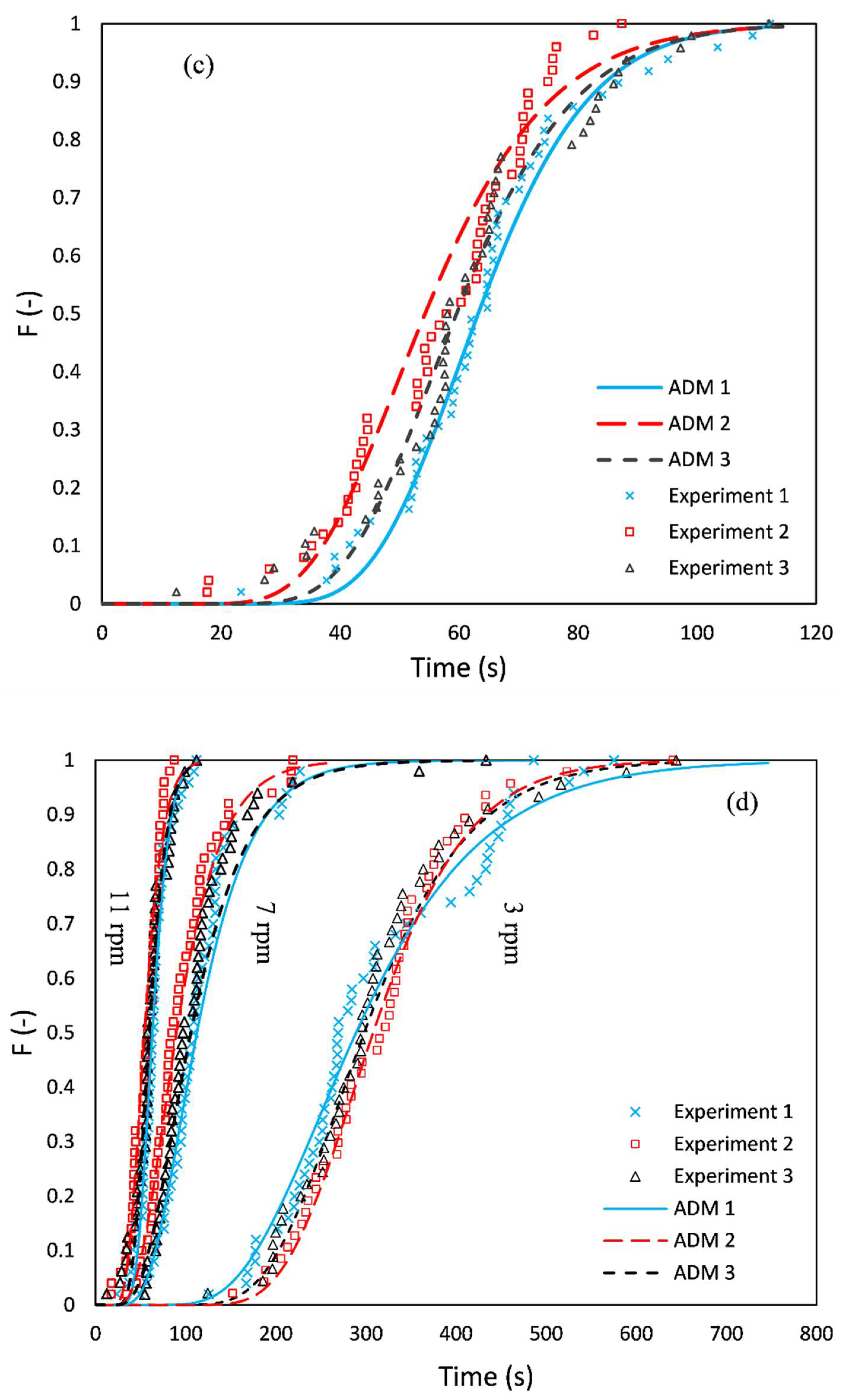
Figure 5d compares cumulative residence time distribution at three different rotation speed. A narrower distribution is obtained due to higher rotation speed. Other researchers have also shown that narrower RTD are obtained when rotation speed increases [
5,
7,
10,
24,
31,
32,
33].
Figure 5e shows the effect of the incline angle on the RTD. When the incline angle increases, the residence time of particles decreases and RTD becomes narrower. Previous studies similarly showed that RTD becomes narrower when incline angle increases [
7,
10,
24,
33].
Figure 5f compares the RTD results of 6 mm at two different flow rates. According to
Figure 5f, an increase in the feed causes a slight shift to higher values of RTD. The shapes of RTD curves at two flow rates are similar. Njeng et al. [
33] showed that feed rate had a slight effect on RTD curves for cuboid particles.
Table 2 shows the results of
Figure 5a–c. MRTs of each row are obtained from the experiment based on Equation (2).
Pe, AASE, and
Dax are obtained from ADM. An increase in the rotation speed led to a decrease in the MRT. The MRT value changes from 313 s to 61 s when the rotation speed is increased from 3 to 11 rpm. Axial dispersion coefficient increases when rotation speed changes from 3 rpm to 7 rpm; however, it decreases when rotation speed changes from 7 rpm to 11 rpm.
In the following sections, we present the effects of rotation speed, incline angle, feed rate, particle size and density on the MRT and the axial dispersion coefficient. All the RTD experimental data and ADM analysis results can be found in the
Supplementary Data that accompanies this article. The data are stored in the spreadsheet (Microsoft Excel) format. The data can be used for validation DEM simulations for non-spherical particles.
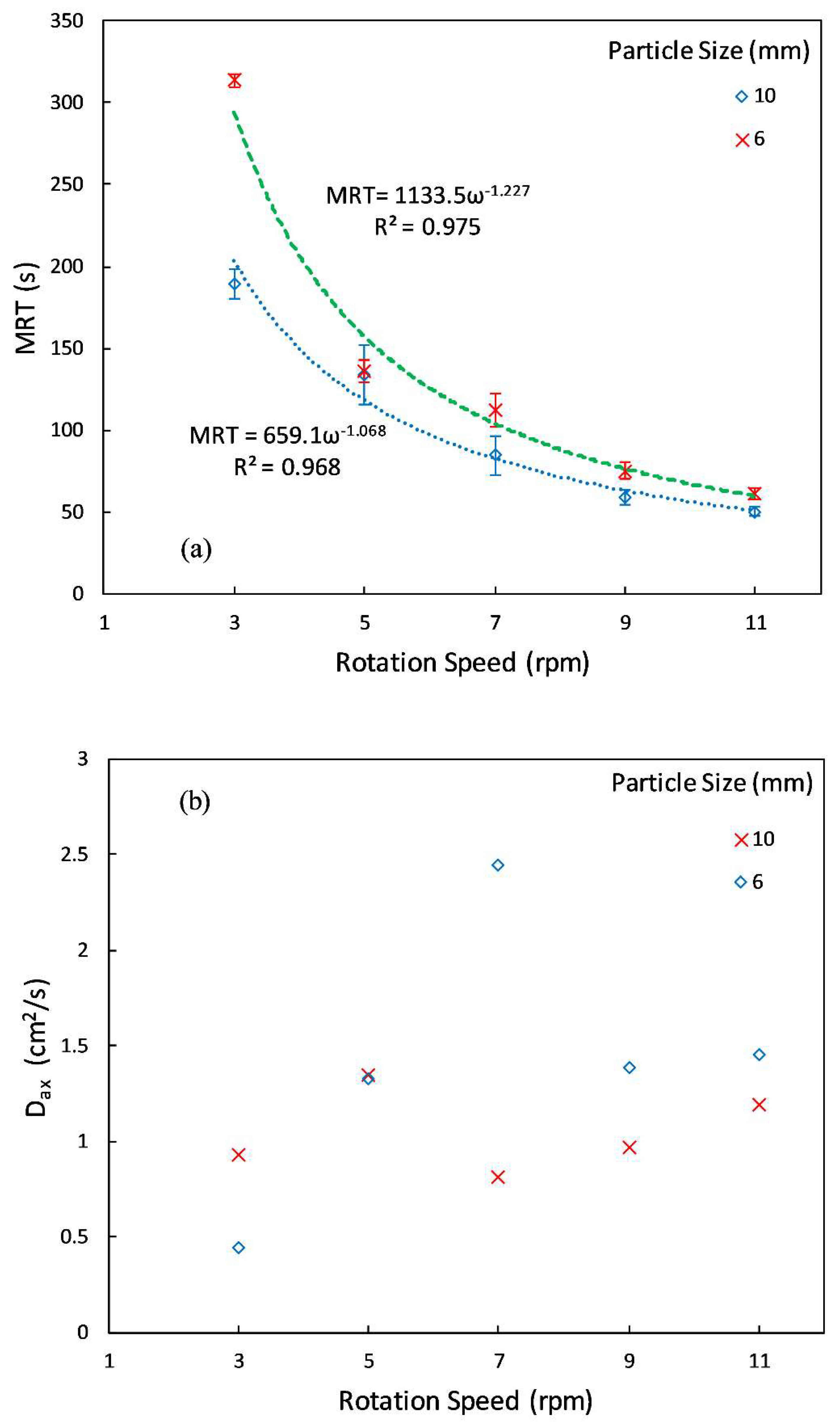
5.1. Effect of Rotation Speed
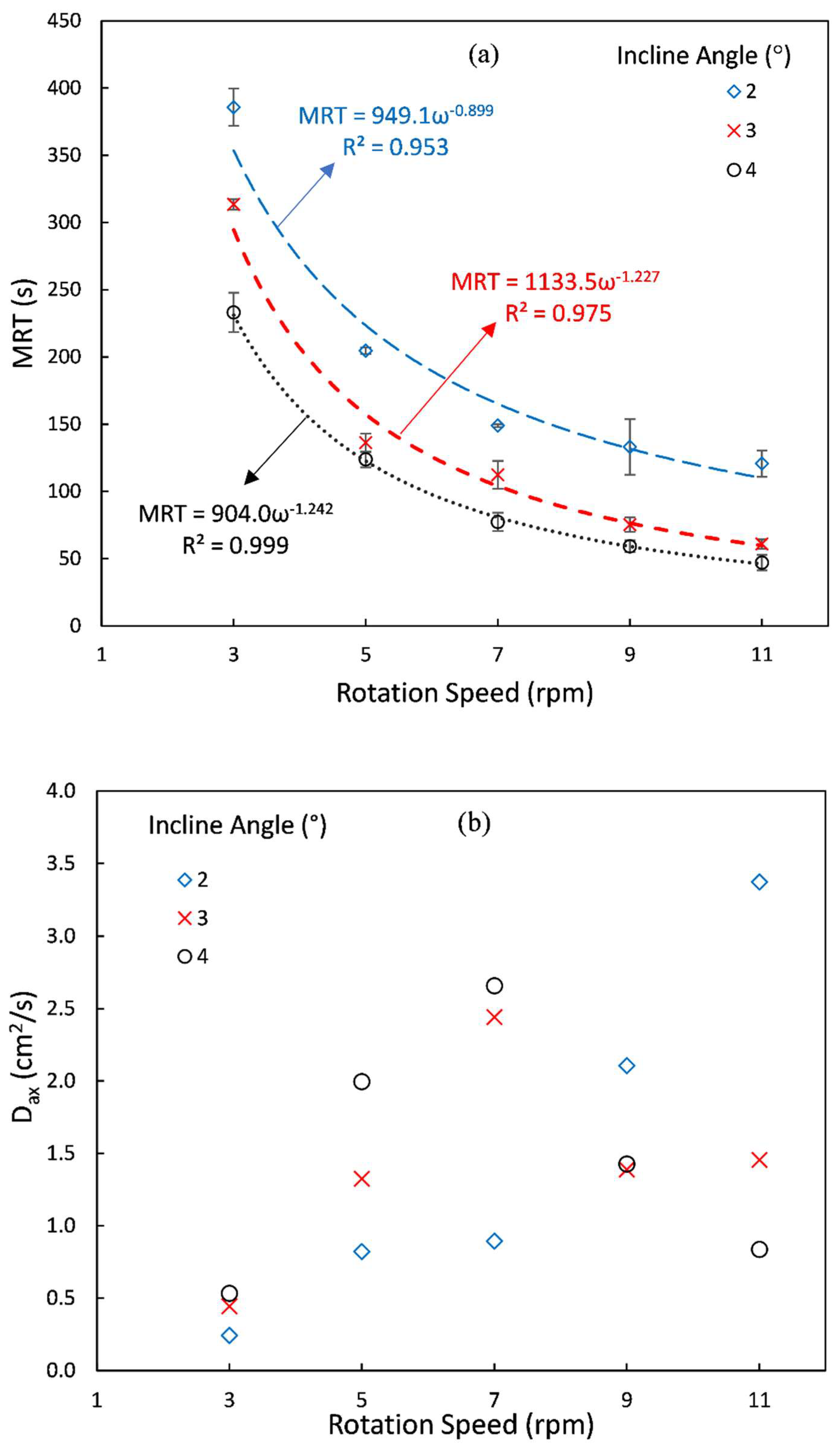
Figure 6a shows the effect of rotation speed on MRT for 6 mm cubes in which rotation speed changes from 3 rpm to 11 rpm at three different incline angles while feed rate is fixed at 1.08 cm
3/s. The error bars also show the interval change in mean with the confidence level of 95%. An exponential model was used to find the relationship between rotation speed and MRT. Regressed equations are presented in the figure. On average, particles remain shorter in the drum when rotation speed increases. At low rotation speeds (3–5 rpm), the rotation speed has a greater effect on MRT than high rotation speeds. MRT decreases when incline angle increases. The figure indicates an overall 69 % decrease in the MRT when the rotation speed changes from 3 rpm to 11 rpm at 2° incline angle. This change in MRT is more notable for higher incline angle values.
When the incline angle increases, the magnitude of exponents of rotation speed (
ω) in the regressed equations in the figure also increases (∣−0.899∣ < ∣−1.227∣ < ∣−1.242∣), which shows that rotation speed has a more pronounced effect on the MRT at higher incline angles. Previous studies showed that
,
, and
for spherical particles [
7,
34,
35]. Njeng et al. [
33] established a relationship for spherical and non-spherical particles (broken rice and beech chips) which shows
. Gao et al. [
5] showed that the effect of rotation speed on the MRT of spherical particles is not same as non-spherical particles (cylindrical and cuboid). Our results show that the magnitude of the exponent for cubic particles with sharp edges is higher than that for spherical and non-spherical particles without sharp edge (see
Table 3 to compare the operating conditions in this research with others).
Figure 6b shows the effect of rotation speed on the axial dispersion coefficient at three incline angles. At 2° of incline angle, the axial dispersion coefficient increases with rotation speed. This behavior can also be seen for other incline angles (3° and 4°) up to 7 rpm, while after 7 rpm, the axial dispersion coefficient decreases. When the rotation speed increases, particles rise to a higher height on the drum wall, detach and avalanche from that height. This means that avalanching particles on the surface have more chance of having random motions on the surface (contrary to the particles in layers below the surface). It should be noted that the axial dispersion coefficient shows random displacement of particles [
10]. Generally, other studies showed that axial dispersion coefficient increases with rotation speed for cohesive powder and catalyst [
7,
31], spherical particles [
10,
11,
34], cylindrical particles [
10,
10,
36], cuboid particles [
33] and cubic particles [
16].
Reviewing the captured movies in the experiments revealed that a change in flow behavior occurs at 9 rpm when the incline angle is 3° and 4° and the bed flow behavior is similar to slumping regime. Sherritt et al. [
37] indicated that for slumping regime, the axial dispersion coefficient decreased when rotation speed increased. Our results beyond 7 rpm at 3° and 4° incline angle show a similar effect. Thus, increasing rotation speed has an inverse effect on axial dispersion coefficient.
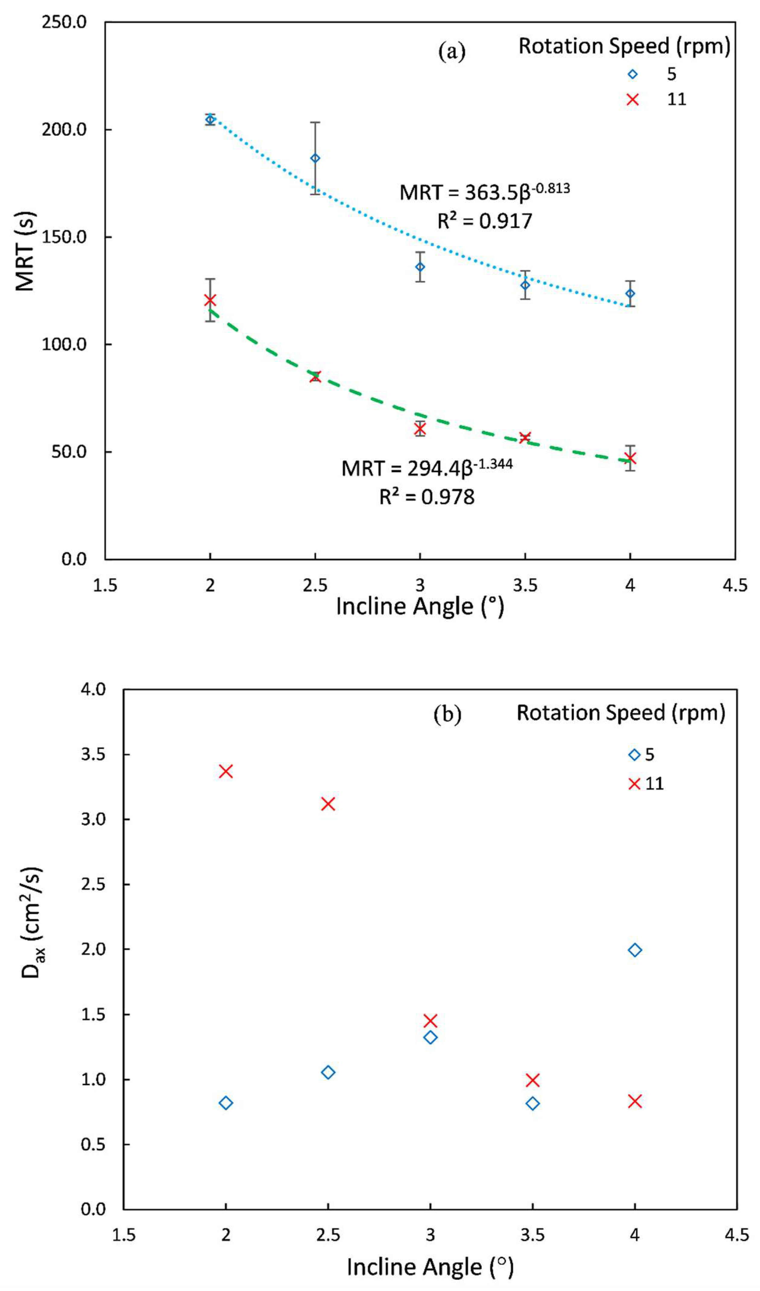
5.2. Effect of Incline Angle
Figure 7 illustrates the effect of incline angle on the MRT and the axial dispersion coefficient.
Figure 7a shows the effect of incline angle on the MRT at two different rotation speeds and feed rate 1.08 cm
3/s for 6 mm cubes. In addition, the power law functions were regressed on the data and equations are presented in the figure. MRT decreases as the incline angle increases. MRT does not change too much between 3° to 4°, while this effect is considerable from 2° to 3°. An increase in the rotation speed at each incline angle causes a shift of MRT to a lower value (almost 80 s in each case). The effect of incline angle on the MRT is similar to the effect of rotation speed, so we can write
(where
β indicates incline angle). The relations
and
can be found for spherical particles [
7,
34,
35], while Njeng et al. [
33] showed that
for spherical and non-spherical particles. Our results show a wider span of exponent for non-spherical particles with sharp edges. This indicates that the incline angle has a stronger dependency on the MRT than it does on spherical and non-spherical particles without sharp edges.
In
Figure 7b, when incline angle increases, axial dispersion coefficient increases (except at 3.5°) at 5 rpm. The standard deviation of axial dispersion coefficient at 3°, 3.5° and 4° are, respectively, equal to 0.058, 0. 376 and 0.803 cm
2/s, which clearly shows that the reduction in the average value at 3.5° is not statistically significant. The axial dispersion coefficient decreases as the incline angle increases at 11 rpm. When the rotation speed is high, the number of particles in the drum is low and only one or, at most, two layers of particles are formed, which means that there is directed motion of particles rather than random motion of particles during avalanching. Consequently, the axial dispersion coefficient decreases.
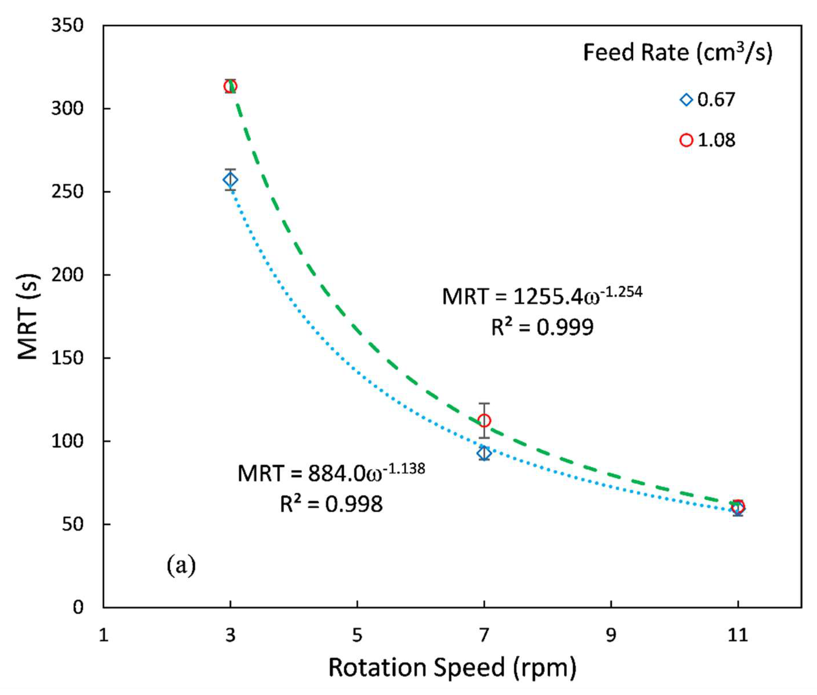
5.3. Effect of Feed Rate
The effects of feed rate on the MRT and the axial dispersion coefficient are shown in
Figure 8 at 3° incline angle for 6 mm cubes. When the feed rate decreases, the number of particles and formed layers decrease, and hence, residence time decreases.
Figure 3a,e illustrate that a decrease in feed rate leads to a decrease in the fill level in the drum. On average, particles remain for a shorter time in the drum when the feed rate decreases. This fact is more considerable at low rotation speeds. When rotation speed increases from 3 rpm to 7 rpm, the flowability of particles in the drum enhances and, hence, the difference between the MRTs of different feed rate decreases. An 11 rpm feed rate does not have a significant effect on the MRT. Other studies also confirm slight effect of feed rate on the MRT. For instance, Gao et al. [
5] observed that the MRT was weakly influenced by feed rate for sphere, cylinder or cuboid. Similar results were observed for cuboid particles by Njeng et al. [
33] and for cylindrical particles by Sudah et al. [
36]. It is noteworthy that changing feed rate can slightly change the MRT, which was reported in previous research [
5,
7,
11,
33,
34,
35,
39,
40]. Our results have good qualitative agreement with other studies [
5,
7,
11,
33,
34,
35,
39,
40].
Figure 8b shows that the feed rate does not have a pronounced effect on the axial dispersion coefficient. At 3 rpm and 11 rpm, the values of axial dispersion coefficient are close together, whereas at 7 rpm they are far from together. In other studies, usually, when the feed rate increased, the axial dispersion coefficient decreased [
10,
33]. This shows that the randomness of particle movement decreases when the feed rate decreases. However, there were some cases in which feed rate had a direct effect on axial dispersion coefficient. Sudah et al. [
36] observed that for cylindrical particles, the axial dispersion coefficient decreased from 0.1 cm
2/s to 0.034 m
2/s when the feed rate increased form 0.46 cm
3/s to 1.83 cm
3/s; and then it gradually increased to 0.042 cm
2/s when the feed rate further increased to 4.34 cm
3/s. Gao et al. [
5] showed that the axial dispersion coefficient of cuboid particles did not change as a function of feed rate, but feed rate had a small effect on the axial dispersion coefficient of cylindrical particles, and had a more noticeable effect on the axial dispersion coefficient of spherical particles. Our results at 7 rpm do not follow these trends from other literature.
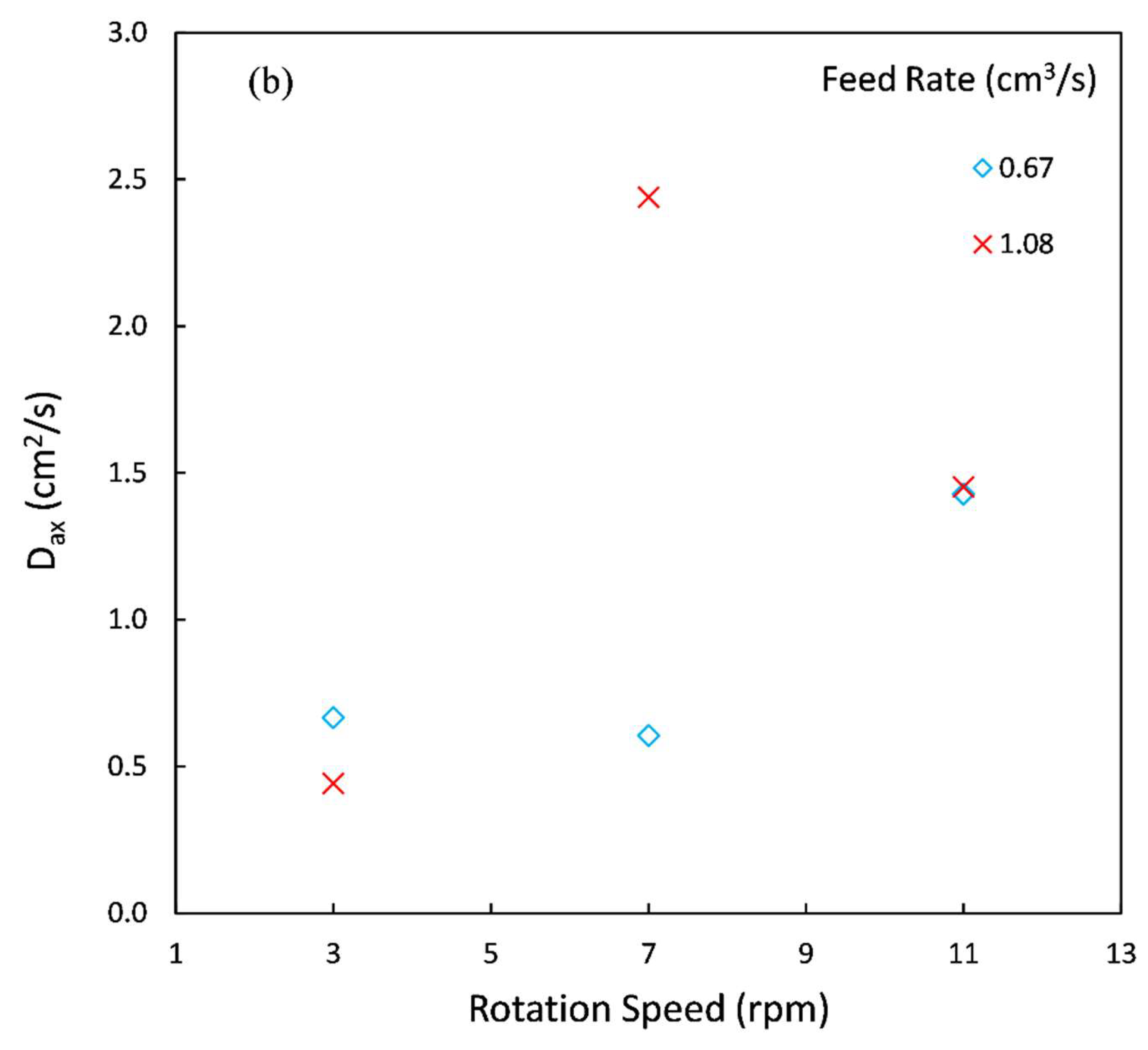
5.4. Effect of Particle Size
Figure 9 shows the effect of particle size on the MRT and the axial dispersion coefficient. To understand the effect of size, 6 mm and 10 mm cubes at 3° were compared at the same volumetric flow rate (1.08 cm
3/s). At these conditions, we observed a lower number of large particles in the drum (see
Figure 3a,f). When size increases, the number of particles decreases and then particle–particle and particle–wall interactions decrease. Then, on average, the MRT decreases with an increase in the size. Other studies also confirm these results [
41,
42]. When rotation speed increases, the flowability of particles in the drum increases, and then the difference between MRT for 6 mm cubes and 10 mm decreases. Nafsun et al. [
43] showed a similar effect of particle size on the thermal mixing time for changes in rotational speed (thermal mixing time is directly proportional to the MRT). They discovered that at a high rotation speed effect of particle size diminishes, but at low rotation speeds, particle size had an significant effect on the thermal mixing time [
43].
The axial dispersion coefficient for larger particles is lower than that for smaller particles (see
Figure 9b). This shows that smaller particles are dispersed better. Rotation speed does not significantly affect the axial dispersion coefficient for 10 mm cubes, while rotation speed has a notable effect on the axial dispersion coefficient for 6 mm cubes (see
Figure 9b). Bensmann et al. [
42] showed that when particle size is increased from 0.55 mm to 1.5 mm, the axial dispersion coefficient is increased from 0.019 cm
2/s to 0.240 cm
2/s, and then decreased to 0.035 cm
2/s.
5.5. Effect of Mixture Composition in the Feed
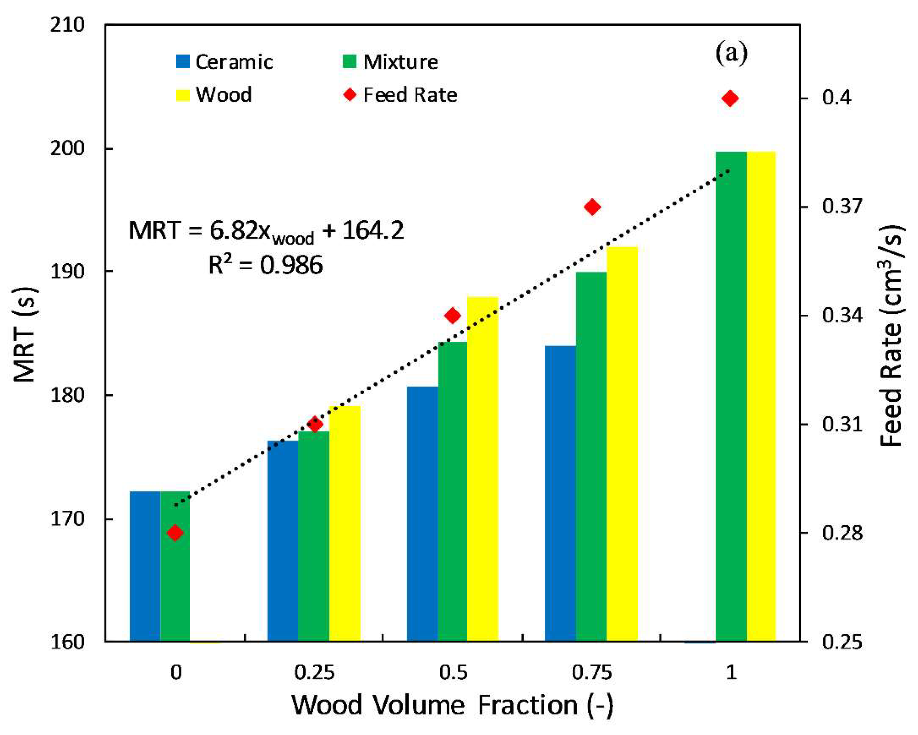
Ceramic and wooden particles of the same size (10 × 10 × 4 mm
3) were entered into the drum to study the effect of volume fraction of heavy and light particles. Rotation speed and incline angle were fixed at 7 rpm, and 2°, while wood and ceramic volume fractions were changed. The number of tracers of each kind (wooden and ceramic) was proportional to the volume fraction of each particle in the mixture. We could not fix the feed rate at the various volume fractions due to the changes in the density. Therefore, in this series of experiments, feeder vibration was kept constant and we let the feed rate change with volume fraction. The feed rate increased when the wood volume fraction increased in the experiments. For example, for pure ceramic (wood volume fraction = 0) the feed rate was 0.28 cm
3/s, while for pure wood, it was 0.40 cm
3/s. In
Figure 8a, we showed that the feed rate does not significantly change the MRT of particles in the drum. Based on this observation, we can still draw some conclusions about the pure effect of wood volume fraction on the MRT (without considering the fact that feed rate changes with wood volume fraction).
Figure 10a shows the effect of wood volume fraction in the feed on the MRT (the ceramic volume fraction is 1-wood volume fraction). Since we could distinguish between wood and ceramic particles in the outlet, we calculated separate MRTs for wooden and ceramic particles. Then, the mixture MRT is calculated by Equation (8).
Wood particles stay for a longer time in the drum than ceramic particles. This is mainly related to the higher weight of the wood particles relative to the ceramic particles. Reviewing the captured movies in the experiment, we observed that the mixture sticks to the wall of the drum and rise with the wall. At a certain point, they detach from the wall and avalanche down. During avalanching, ceramic particles travel a longer axial distance (the drum is inclined). This process is repeated a number of times until the particles exit the drum. Thus, ceramic particles stay a shorted time in the drum. The MRT of the mixture is also shown in this figure. We provided a linear regression for the MRT of the mixture as a function of wood volume fraction. It clearly shows that the MRT of the wood and ceramic mixture (particles with different densities) can be linearly interpolated by using the MRTs of pure particles. The regressed line of the MRT of the mixture in
Figure 10a shows that the MRT of mixture is a linear function of wood volume fraction:
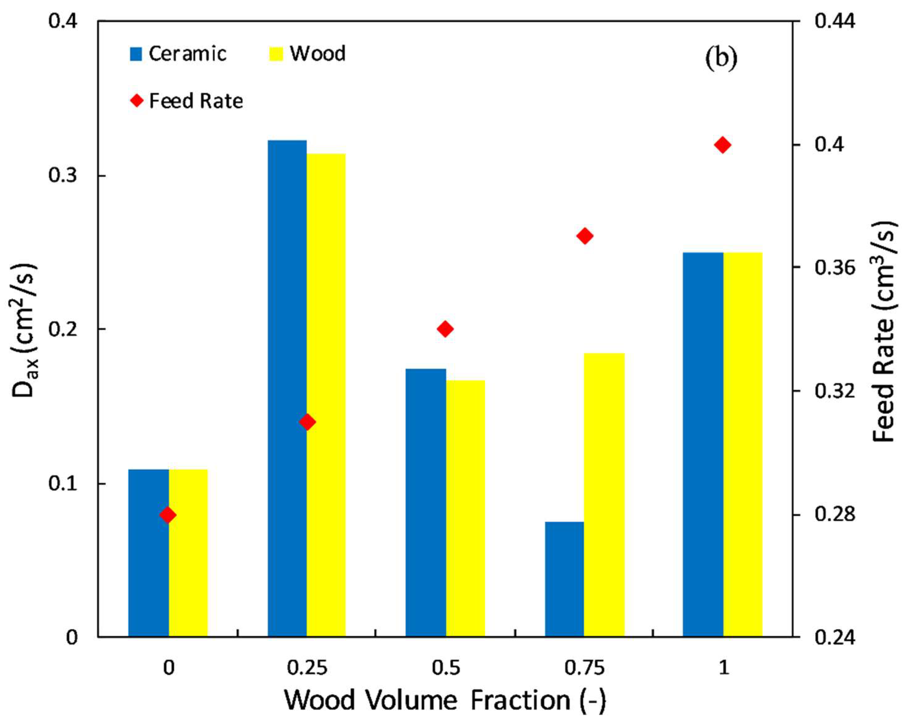
Figure 10b shows the effect of wood volume fraction on the axial dispersion coefficient. When wood volume fraction changes, the axial dispersion coefficient does not change notably. Therefore, a change in the wood volume fraction in the mixture does not have a significant effect on the axial dispersion coefficient in this range of operating conditions. We could not find a clear trend for axial dispersion coefficient; however, the maximum of axial dispersion values was observed at the wood volume fraction of 0.25.
6. Conclusions
Understanding the motion pattern of non-spherical particles in a continuous rotary drum is of great importance for design and scaleup of pyrolysis processes, food manufacturing processes, etc. The motion pattern of spherical particles is characterized by RTD measurements that reflect the cumulative effect of motion of individual particles in the drum. RTD was measured in a continuous rotary drum with the length 50.0 cm and internal diameter 8.4 cm, using colored particles as tracers. Non-spherical particles with sharp edges were selected in the experiments, since in practice we are facing this class of shapes rather than spherical or non-spherical particles without sharp edges.
Particles with two sizes, 6 and 10 mm, and two densities, 750 and 2085 kg/m
3, were used in experiments. We included the particles with two densities in our experiments to resemble the condition in which wooden particles (as pyrolysis media) are processed along with ceramic materials (as heat carrier media). In the experiments, rotation speeds varied between 3 and to 11 rpm; incline angle, between 2 and 4°; and feed rate, between 0.28 cm
3/s to 1.08 cm
3/s. The effect of mixture composition (a mixture of low- and high-density particles) on the RTD was also investigated. We also fitted the RTD data with the axial dispersion model to obtain a better insight on the flow behavior of particles in the drum. The results were compared with those from similar studies on spherical and non-spherical particles without sharp edges to better understand the similarities and differences between the two (particles with sharp edges and without sharp edges). All the experimental results on RTD are also provided as
supplementary data to be used by other researchers who are aiming to validate their DEM simulation results.
Our results showed that the MRT of non-spherical particles with sharp edges depends on ω−α similar to other shapes (spherical and non-spherical particles without sharp edge), but the exponent is higher in our experiments (0.9 < α < 1.24), especially at high incline angles. At rotation speeds between 3 and 7 rpm, the axial dispersion coefficient increased with rotation speed, while this trend was not observed with further increase in the rotation speed due to change in the flow regime in the drum. The MRT also depends on incline angle MRT ∝ β−b, where b varies between 0.81 (at low rotation speed) to 1.34 (high rotation speed). However, the exponent b is closer to 1 for other particles with other shapes, suggesting the more pronounced role of incline angle on the particle motion for particles with sharp edges. The axial dispersion coefficient increases with incline angle at 5 rpm and it decreases with increasing the incline angle at 11 rpm. When feed rate increases, fill level increases, and consequently the MRT increases, especially at low rotation speed. Feed rate does not affect the axial dispersion coefficient in our experiments. Smaller particle has higher MRT than bigger particle. We could show that the value of α in the relation MRT ∝ ω−α is higher for smaller particles and the difference between MRT of large and small particles diminishes as the rotation speed increases. Rotation speed has a significant effect on the axial dispersion coefficient of 6 mm cubes, while rotation speed has a small effect on the axial dispersion coefficient of 10 mm cubes. Wooden particles (low density) have higher MRT than ceramic particles (high density). For a mixture of wooden and ceramic particles, the MRT linearly increases with volume fraction of wooden particles in a mixture. The MRT of mixture scales with the MRT of pure wooden and ceramic particles, with volume fraction as the scaling factor.


 ,
, 


