Article

Design and Control of Extractive Dividing Wall Column for Separating Dipropyl Ether/1-Propyl Alcohol Mixture

1
School of Chemical Engineering, East China University of Science and Technology, Shanghai 200237, China
2
College of Environmental and Chemical Engineering, Shanghai University of Electric Power, Shanghai 200090, China
*
Author to whom correspondence should be addressed.
Processes 2022, 10(4), 665; https://doi.org/10.3390/pr10040665
Submission received: 3 March 2022 / Revised: 20 March 2022 / Accepted: 26 March 2022 / Published: 29 March 2022
(This article belongs to the Topic Chemical and Biochemical Processes for Energy Sources)

Abstract

:
The focus of this work is the study of the extractive dividing wall column (EDWC) for separating the azeotropic mixture of dipropyl ether and 1-propyl alcohol with N, N-dimethylacetamide (DMAC) as the entrainer. Three separation sequences are investigated, including a conventional extractive distillation sequence (CEDS), EDWC and a pressure swing distillation sequence (PSDS). The static simulation results showed that the EDWC with DMAC as the entrainer is more economically attractive than CEDS and PSDS. Subsequently, a control structure CS1 based on a three-temperature control loop and a control structure CS2 with the vapor split ratio as the manipulated variable are investigated for the EDWC. Their dynamic control performances are evaluated by facing large feed flow rates and composition disturbances. The results showed that the CS1 can deal with feed flow rate disturbance effectively. However, the transient deviation is large and the settling time is too long when facing feed flow composition disturbances. The CS2 can quickly and effectively deal with feed flow rate and composition disturbances, and it can maintain the two products at high purity.

1. Introduction

Dipropyl ether (DPE) is a flammable, colorless liquid with a boiling point of 90.08 °C. It is used mainly as a gasoline additive, stabilizing agent and industrial solvent [1]. 1-propyl alcohol (PA) is a highly flammable, colorless liquid with a boiling point of 97.1 °C. 1-propyl may be used in several applications such as personal care products, cosmetics, pharmaceuticals and solvent, as well as an intermediate for the production of methyl isobutyl ketone, amines, acetone and glycerol [2]. Dipropyl ether can be synthesized by the dehydration of 1-propyl alcohol with sulfuric acid, but the mixture of dipropyl ether and 1-propyl alcohol is an azeotropic mixture and it cannot be completely separated by a simple distillation process.
Much research has been focused on the selection of a separation process for the azeotropic mixture of dipropyl ether and 1-propyl alcohol. Lladosa et al. [3] designed a pressure swing distillation process and an extractive distillation process with 2-ethoxyethanol as an entrainer. Their results showed that pressure swing distillation can reduce the total annual cost by 29.46% compared with that of the extractive distillation process. Mangili [4] further proposed two improved processes based on vapor recompression and direct heat integration, and the results showed that the two improved processes can be increased by 68.69% and 39.54%, making them more economically attractive than the pressure swing distillation process. Luo et al. [5] designed an extractive distillation with 2-methoxyethanol as an entrainer and a heat-integrated pressure swing distillation to separate isopropyl ether/isopropanol azeotropic mixture. Their results revealed that the heat-integrated pressure swing distillation process could reduce the total annual cost by 5.75% compared with that of the extractive distillation process. An extractive distillation under lower pressure was redesigned by You et al. [6]. It was found that the extractive distillation process under lower pressure could reduce the total annual cost by 7.6%.
Dividing wall columns (DWCs) have attracted wide attention because they can greatly reduce the energy consumption of the distillation process. The internal space of the DWC is divided by a dividing wall to realize the separation of the ternary mixture in one column. Compared with the conventional distillation sequence, DWC reduces the number of condensers and reboilers, and thermodynamically reduces the effect of remixing in the column. Generally, DWC can save about 30% of capital costs and energy compared with conventional separation sequence [7,8,9,10].
Applying the DWC technology to the extractive distillation process is the extractive dividing wall column (EDWC, see Figure 1a). A dividing wall is added to divide the column into three parts. The feed and the entrainer is fed into the extractive distillation section C1. The entrainer S and components B enter the public stripping section C3, which are finally separated in the entrainer recovery section C2. The AB components are withdrawn from both sides of the column top, respectively. The entrainer is recycled from the bottom of the column. In order to balance the loss of entrainer caused by distillates, it is necessary to add a makeup stream. Figure 1b is the equivalent two columns model commonly used to simulate the EDWC. The entrainer recovery section is simulated by a column C2 without reboiler. The extractive distillation section and the public stripping section are combined into a column C1 for simulation.
Compared with the conventional extractive distillation sequence, EDWC has one reboiler, and the structure of the dividing wall also increases the complexity of the structure in the column. Therefore, the control structure of the EDWC is the key factor for its industrially implementation. Wu et al. [11] investigated the acetone/methanol system and designed a three-temperature control loop based on the conventional extractive distillation sequence, two condensers and one reboiler control three parts of the temperature control tray to achieve the stability of product purity. Xia et al. [12,13] investigated the methylal/methanol system and designed two control structures. The first control structure includes four composition controllers and an adjustable vapor split ratio, however, when faced with a decrease in the feed flow rate, the purity of the methanol product decreased relatively quickly. On this basis, the author proposed an improved control structure based on the differential temperature control, which effectively suppresses the offsets of methanol product purity. Zhang et al. [14] investigated the ethyl acetate/isopropanol system, and used a three column model to simulate the EDWC, and optimized the column structure with the goal of minimal total annual cost. Subsequently, three control structures were proposed, in addition to the three-temperature control loop structure, the two improved structures with the entrainer flow rate and the vapor split ratio as the control variables were investigated. The dynamic simulation results showed that the two improved structures have excellent dynamic performance.
Although the control structure for controlling the vapor split ratio has achieved good dynamic performance in simulation, it is difficult to achieve in industrial application. Recently, many researchers [15,16,17,18,19,20] have designed a special internal column to directly control the vapor split ratio of DWC in laboratory devices. Luyben [21] proposed changing the vapor split ratio by varying the pressure on both sides of the EDWC. Jing et al. [22] added a pressure compensation, based on Luyben’s research, to further improve the dynamic performance. Zhu et al. [23] realized the control of the vapor split ratio by adding an intermediate reboiler in the extractive distillation section.
In addition, a variety of new control systems were used in the control of the EDWC, such as artificial neural network [24,25], model prediction control [26,27,28,29], which showed good dynamic performance when controlling the EDWC.
In this paper, the conventional extractive distillation sequence (CEDS), the EDWC, and the pressure swing distillation sequence (PSDS) were designed and optimized using N, N-dimethylacetamide (DMAC) as the entrainer. Then, the three processes were compared through economic analysis. Finally, a control structure CS1 based on a three temperature control loop and a control structure CS2 with vapor split ratio as the manipulated variable are investigated to control the EDWC.

2. Steady State Design

2.1. Materials and Methods

The feed flow rate was 100 kmol/h, and the feed composition was 50/50 mol% DPE/PA. The production specifications of DPE and PA reached 99.9 mol%. The condenser pressure was set to 101.325 kPa. The pressure drop of each tray was 0.69 kPa.
The steady-state and dynamic simulations were implemented by Aspen Plus V9.0 and Aspen Dynamics V9.0 commercial software, the DSTWU module for shortcut calculations and RadFrac module for rigorous simulations. According to thermodynamic behaviors of ternary system of DPE + PA + N, N-dimethylformamide, the UNIQUAC model was suitable to describe the ternary system [30]. Thus, the UNIQUAC model was applied to predict the vapor–liquid equilibrium in the simulations.
In this work, the minimal total annual cost (TAC) was the optimization goal, which is defined as the sum of the annual operation costs and capital investments divided by the three-year investment payback period. The capital investments are mainly composed of the column vessels, two condensers, and one reboiler. Here, it is assumed that the heat transfer coefficients of the condenser and the reboiler are 0.852 kW/(K·m2) and 0.568 kW/(K·m2). Some items are usually not considered because the cost of trays, reflux drums, pipelines, pumps, valves is much less than the cost of the column vessels and heat exchanger. For the above basis of the assumption and more calculation details, please refer to Luyben’s book [31].
The mainly optimized design variables include the number of stages NT, the feed stage NF, the entrainer feed stage NFE when design CEDS and EDWC, and the reflux ratios of the columns.
The optimization strategies mainly include: varying the reflux ratio to meet the production specifications, adjusting the feed stage to minimize the reboiler duty and varying the number of stages to minimize the TAC.

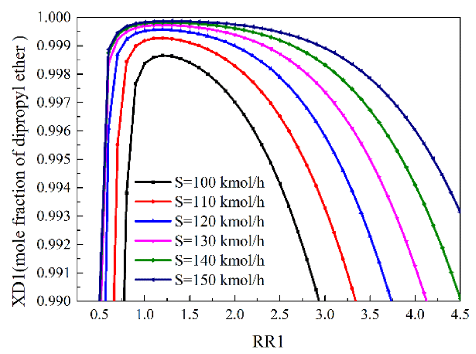
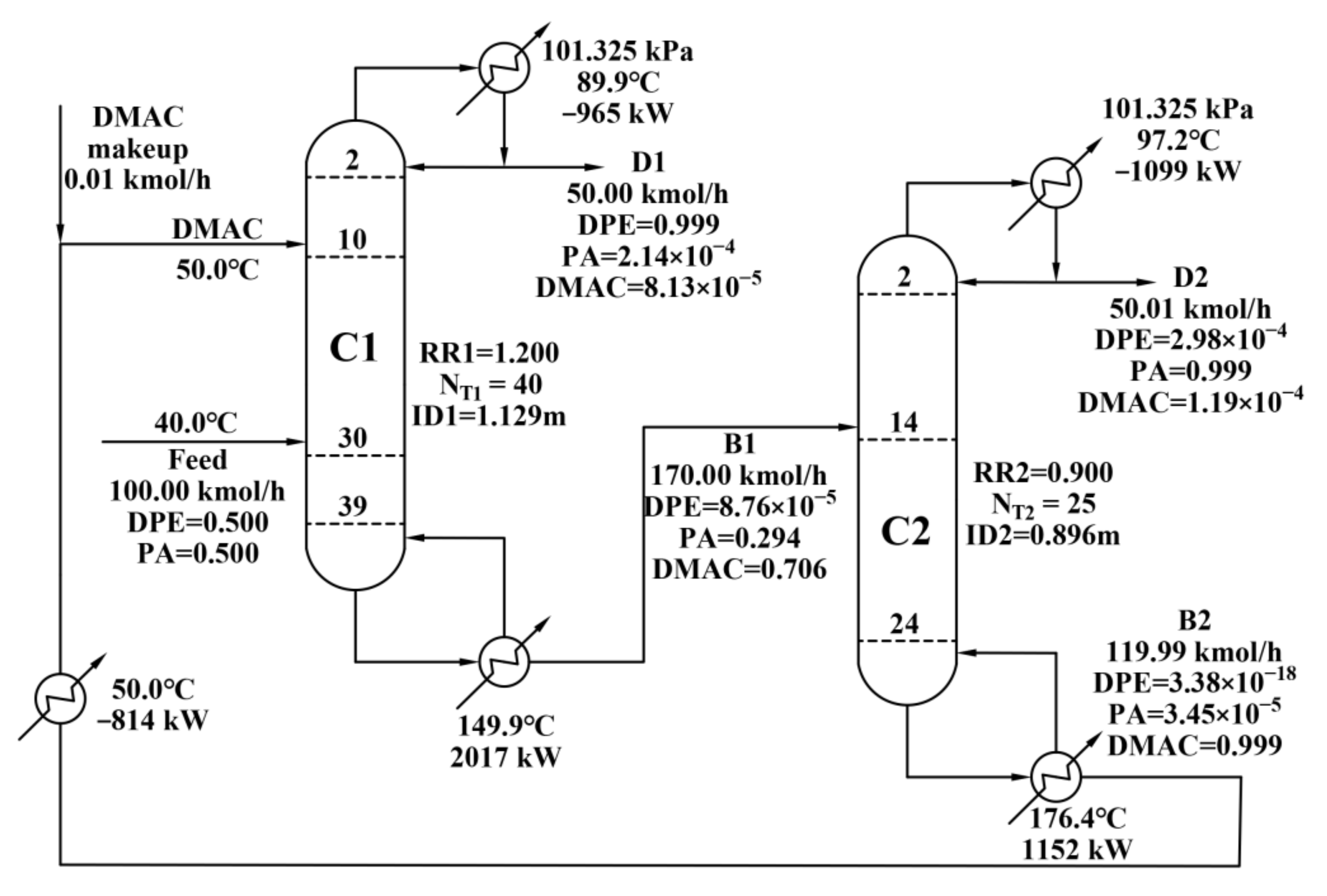
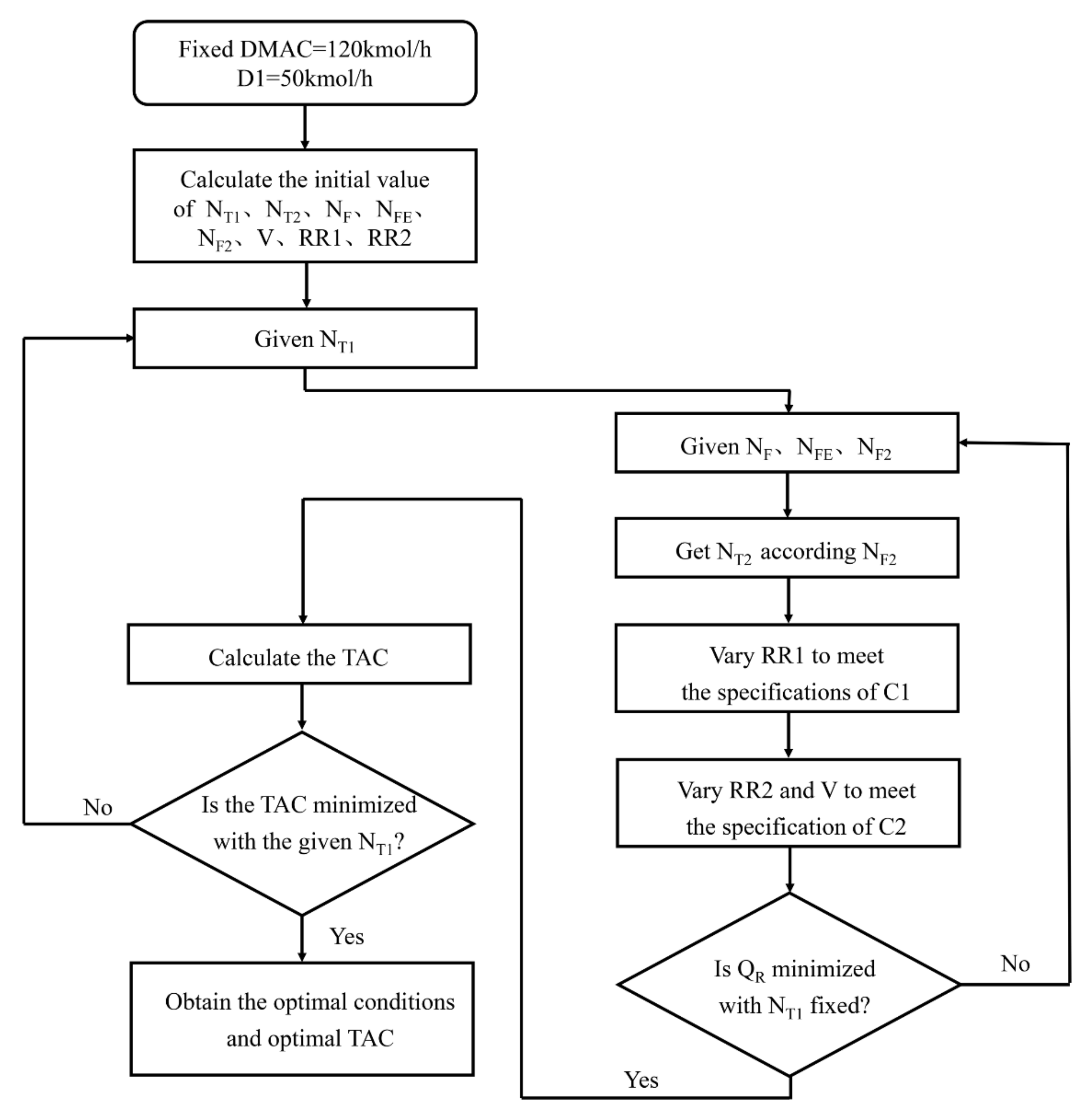
2.2. Steady State Design for CEDS

For the extractive distillation, it was necessary to select the entrainer and its flow rate. N,N-dimethylformamide is the best entrainer for separating DPE and PA [3]. However, it is not an environmentally friendly solvent or entrainer. Hence, in this work, DMAC was selected as the entrainer, which shows similar properties as N, N-dimethylformamide was selected as the entrainer.
The effect of entrainer flow rate S and reflux ratio RR1 on the concentration of light component DPE was determined by sensitivity analysis. As illustrated in Figure 2, the increase of S resulted in the improvement of the purity of DPE product. Additionally, the purity of DPE product first improved and then reduced with the increase of RR1. Obviously, the increase of RR1 can prevent more entrainer entering the column top, thereby improving the purity of DPE product. However, too large RR1 also leads to the dilution of the concentration of DMAC by the surplus DPE, so that more component PA enters the top of the column. In order to achieve the production specifications, the entrainer flow rate was selected as 120 kmol/h, and the reflux ratio of the extractive distillation column C1 was selected as 1.2. Figure 3 shows the final optimization results and detailed information of each steam, heat duties and the size of the column.

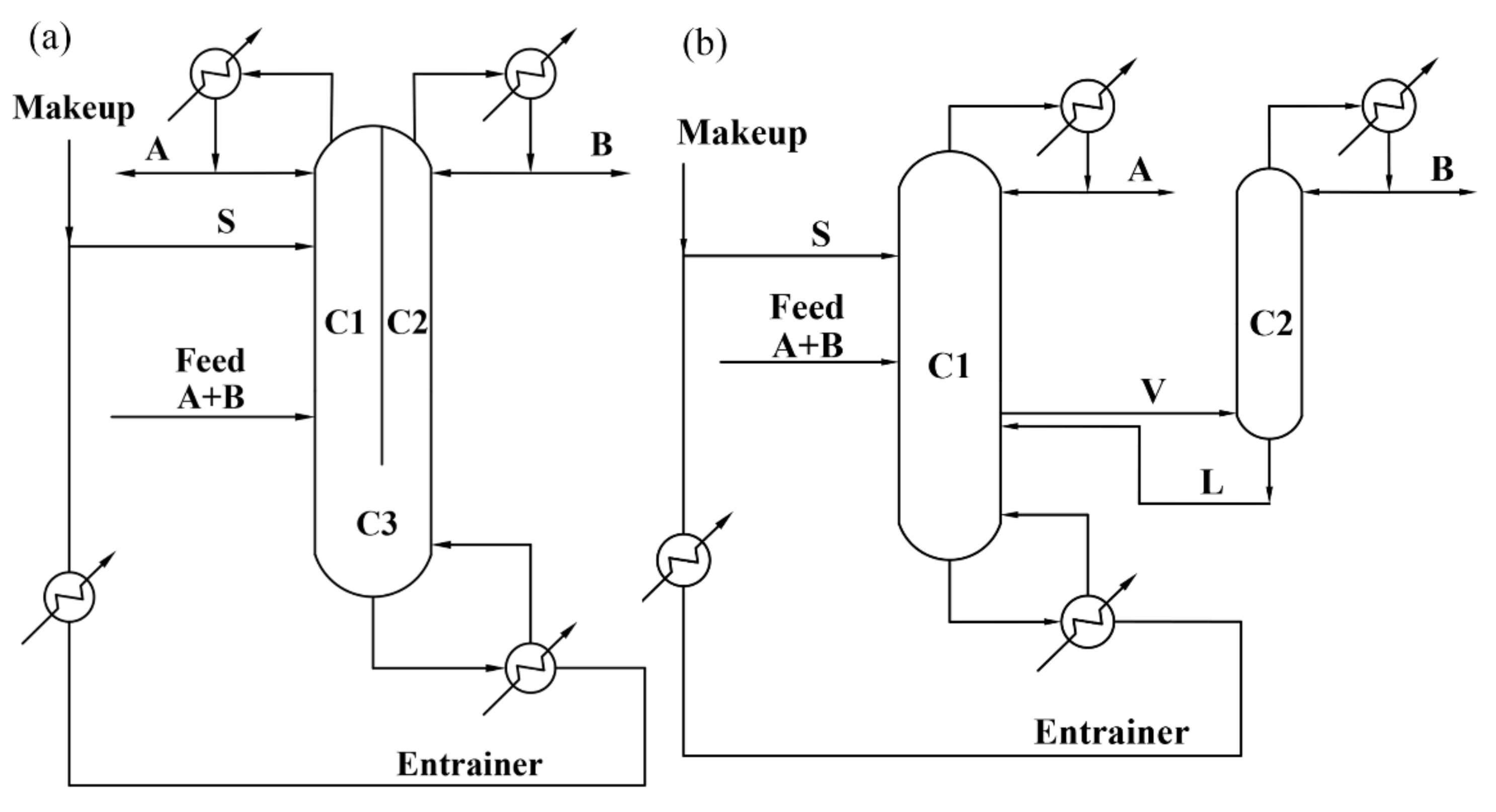
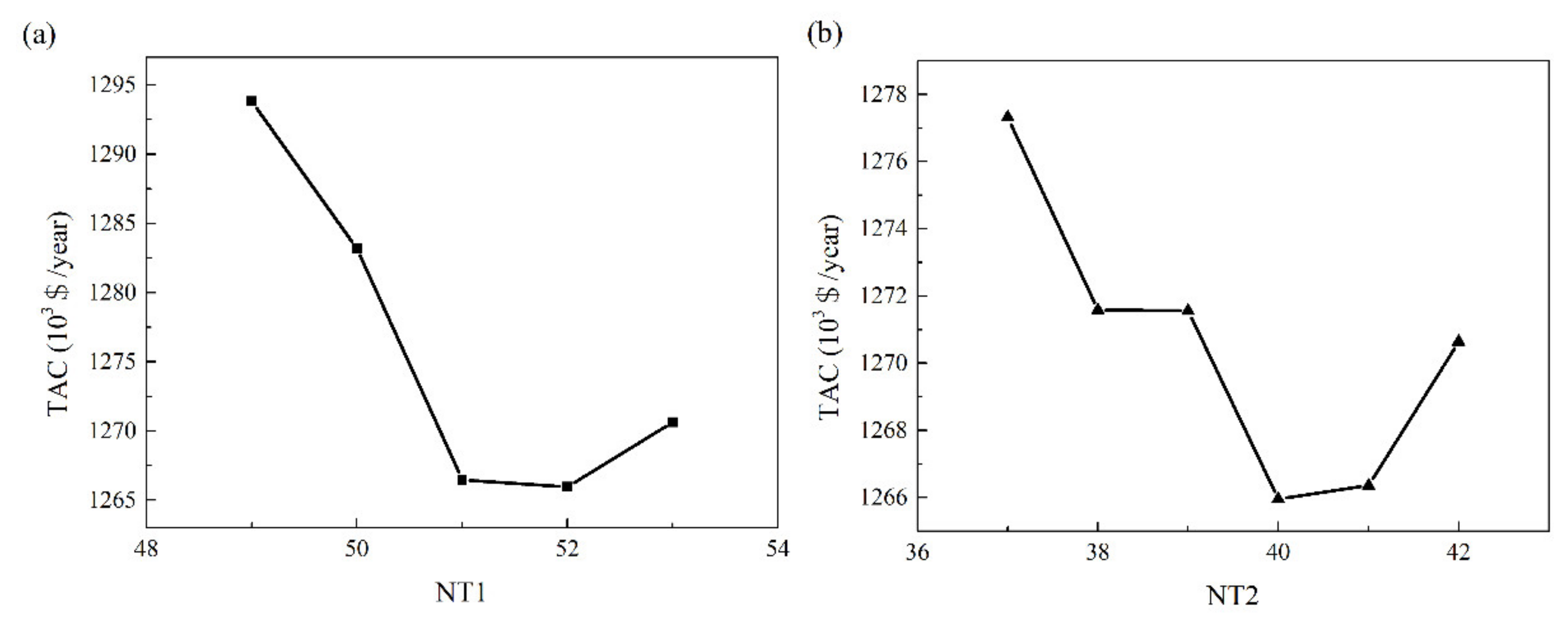
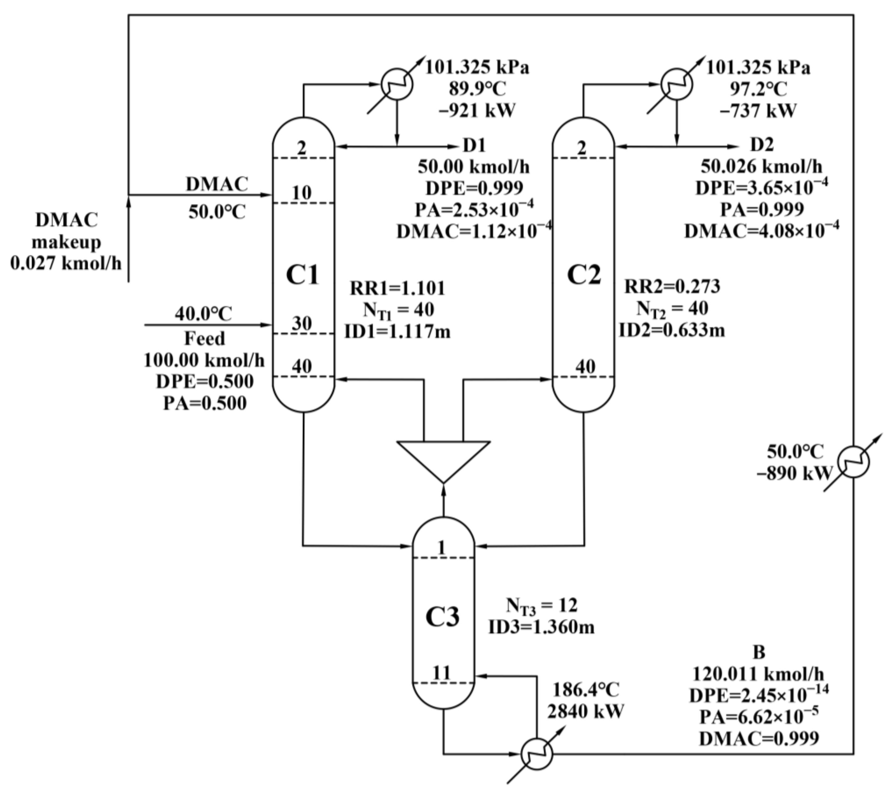
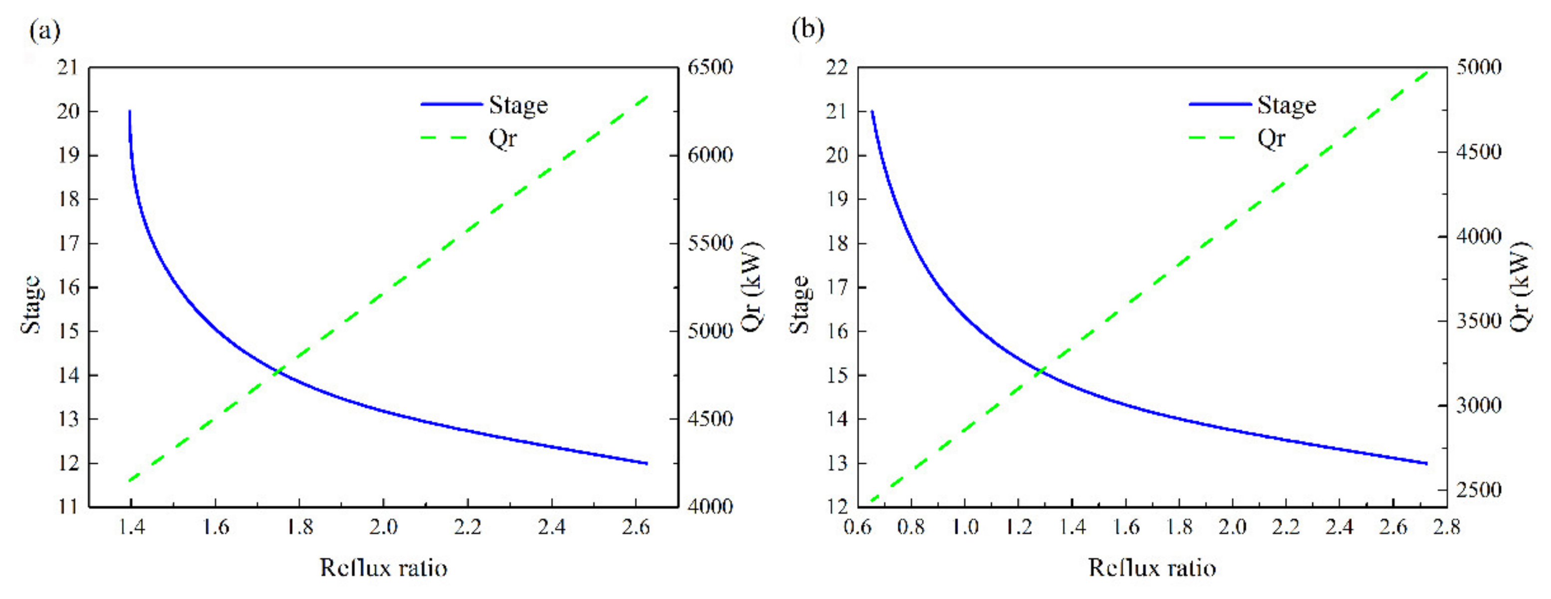
2.3. Steady State Design for EDWC

According to the design results of the CEDS, the initial values of the structural parameters of the two column model (as shown in Figure 1b) were obtained. First, the entrainer recovery column in the CEDS was separated from the feed in two parts, the rectification section parameter of the entrainer recovery column was simulated with a column C2 without reboiler. After the reboiler was removed from the extractive distillation column, the structural parameters of the stripping section of the entrainer recovery column were simulated by column C1. Then, the number of stages and the total pressure drop of the C2 column were increased to be the same as that of the dividing wall of the C1 column. Finally, by adjusting the vapor flow rate V2 between the two columns and the reflux ratio of the two columns, the purity of the top products meets the production specifications [11].
The optimized design variables include the number of stages NT1 of the C1 column, the mixture feed stage NF, the entrainer feed stage NFE, C2 column feed location NF2 (also the position of the dividing wall) and the number of stages NT2 (NT2 = NF2 − 1), the vapor flow rate V2 between the two columns, and the reflux ratios RR1 and RR2 of the two columns. Figure 4 illustrates the optimization procedure of the EDWC.
The influence of the number of stages NT1 of the C1 column and the number of stages NT2 of the C2 column on the TAC of the EDWC is depicted in Figure 5. Obviously, the optimized NT1 and NT2 were 52 and 41, respectively. Figure 6 shows the final optimization results of the EDWC and the detailed information of each stream, heat duties, and the size of the column. As shown in Figure 6, the feed stage NF was 30, and the entrainer feed stage NFE was 10. The vapor stream flow rate V2 to the C2 column was 60 kmol/h (the vapor flow rate V1 to the C1 column was 158.5 kmol/h, thus the vapor split ratio α = V1/(V1 + V2) = 0.7254). The reflux ratio RR1 was 1.101, and RR2 was 0.273. The three parts of the EDWC share a column vessel, and the upper section is divided into two sections with a dividing wall. To determine the actual diameter, the concept of equivalent diameter needs to be introduced [10]. The diameter of the C1 section was 1.117 m, and the diameter of the C2 section was 0.633 m. The equivalent diameter De can be calculated to be 1.284 m. Because the diameter of the public stripping section C3 was 1.360 m larger than the equivalent diameter De, the diameter of the EDWC was determined to be 1.360 m.

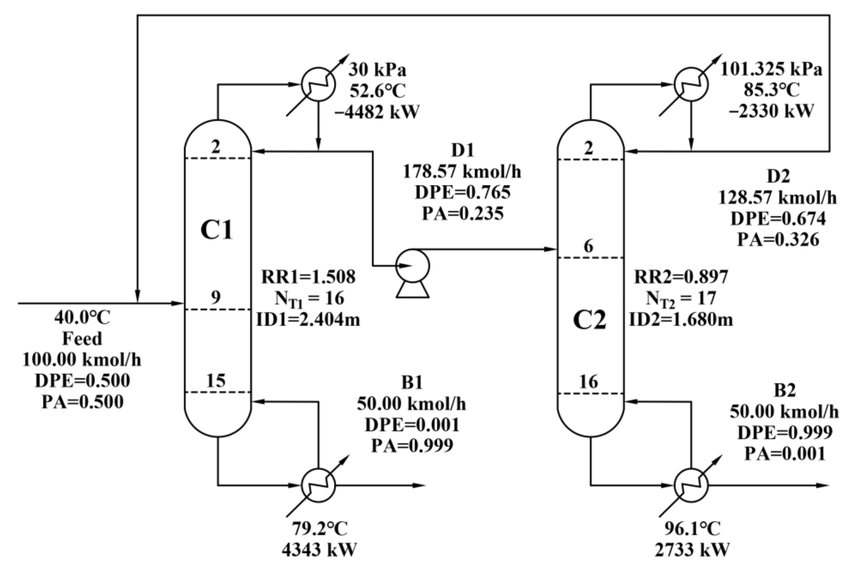
2.4. Steady State Design for PSDS

According to the pressure swing distillation designed by Lladosa et al. [3], the pressure of the low-pressure column is 30 kPa, the composition of DPE at the top of the column is 0.765. The pressure of the high-pressure column is 101.325 kPa, the composition of DPE at the top of the column is 0.674.
First, mass balance calculations were carried out based on the new feed flow rate and production specifications. The calculated distillate rate of the low-pressure column C1 was 178.57 kmol/h, and the distillate rate of the high-pressure column C2 was 128.57 kmol/h. The flow rates of PA and DPE products were 50.00 kmol/h. Then according to the results of the material balance, the structural parameters of the low-pressure column C1 and the high-pressure column C2 were optimized. Figure 7 shows the variation of stage number and heat duty as a function of the reflux ratio for the C1 (a) and C2 (b), it can be determined that the number of stages in the low-pressure column C1 is 16, the feed location is 9, the number of stages in the high-pressure column C2 is 17, and the feed location is 6. Figure 8 shows the final optimization results of the PSDS and the detailed information of each stream, heat duties, and the size of the column.

2.5. Comparisons and Analysis of CEDS, EDWC and PSDS

Table 1 summarizes the optimization results of CEDS, EDWC and PSDS. Compared with the CEDS, the EDWC can save 12.45% of capital investments, 10.38% of operation costs, and TAC reduction of 11.01%. Compared with the PSDS, the EDWC can save 41.49% of capital investments, 47.07% of operation costs, and 45.50% of TAC. The results show that the EDWC with DMAC as the entrainer is more economically attractive than the CEDS and the PSDS.

3. Control Structure for EDWC

Two control structures CS1 and CS2 are proposed for the dynamic control of EDWC. A three-temperature control loop CS1 was developed, RR1, RR2 and QR were used as the manipulated variables to control the reference stages from C1, C2, and C3, respectively. Subsequently, an improved control structure CS2 with combining active vapor split ratio α into CS1 was developed.

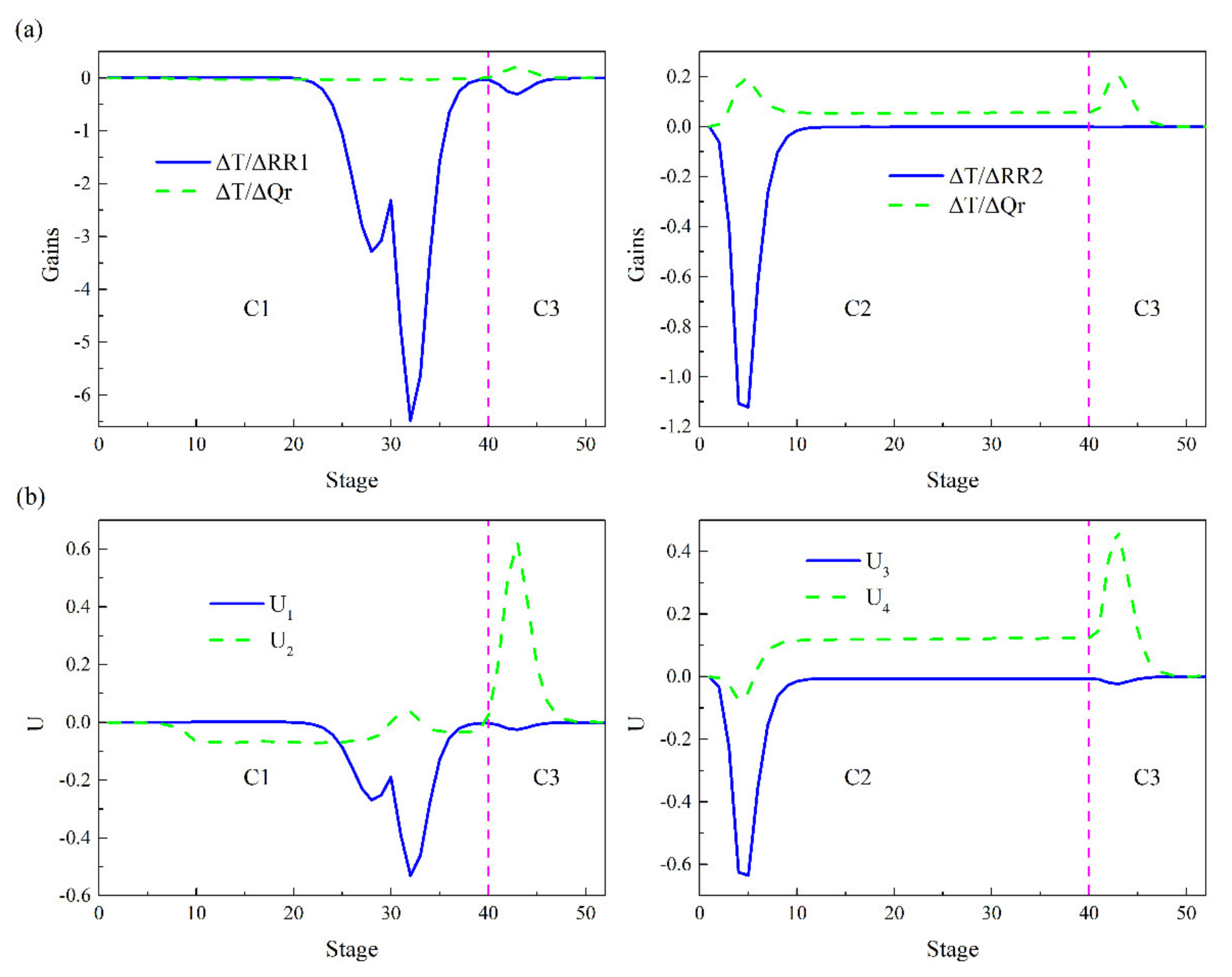
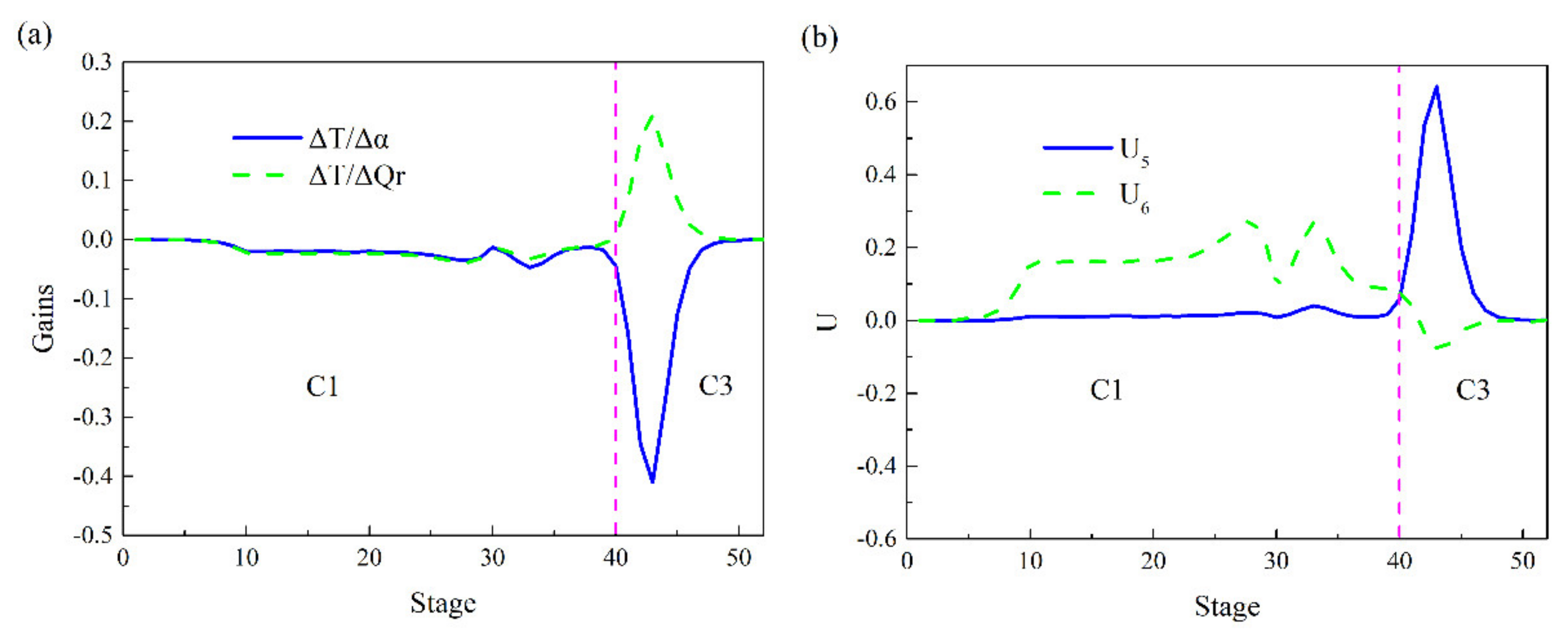
3.1. Selecting Temperature Control Trays

For the selection of the temperature control tray, there are usually methods such as slope criterion, sensitivity criterion, and singular value decomposition (SVD) criterion. The singular value decomposition method has the advantages of simplicity and effectiveness, and is widely used in the selection of the temperature of the control tray in the distillation process [32,33,34]. In this work, the SVD method was used to select the temperature of the control tray. A small change (+0.1%) was applied to one of the three independent variables (RR1, RR2, and QR) while keeping the other two variables constant. The steady-state gain of all manipulated variables can be achieved by dividing the change in each stage temperature by the change in the manipulated variable. As a result, a gain matrix K with NT rows and two columns (the number of manipulated variables) was obtained. The gain matrix K was decomposed into three matrices by the SVD function in Matlab: K = UσVT. The tray corresponding to the largest magnitude in the U vector is the control tray.
Figure 9a shows the steady-state gains of the C1, C2 and C3 column when RR1, RR2, and QR were used as manipulated variables, the left and right of the vertical dashed line represent different columns of the EDWC. Figure 9b shows the corresponding values of the U from singular value decomposition analysis, where the U1 largest magnitude represented by the solid line appears on stage 32, the corresponding manipulated variable was RR1. The largest magnitude of the solid line U3 appeared at stage 5, the corresponding manipulated variable is RR2. The U3 and U4 largest magnitudes indicated by the dashed line both appear at stage 43 (stage 3 of the C3 column), the corresponding manipulated variable was QR. Finally, the reflux ratio RR1 of the C1 column controlled the temperature of stage 32, the reflux ratio RR2 of the C2 column controlled the temperature of stage 5, and the heat duty QR controlled the temperature of stage 3 of the C3 column.

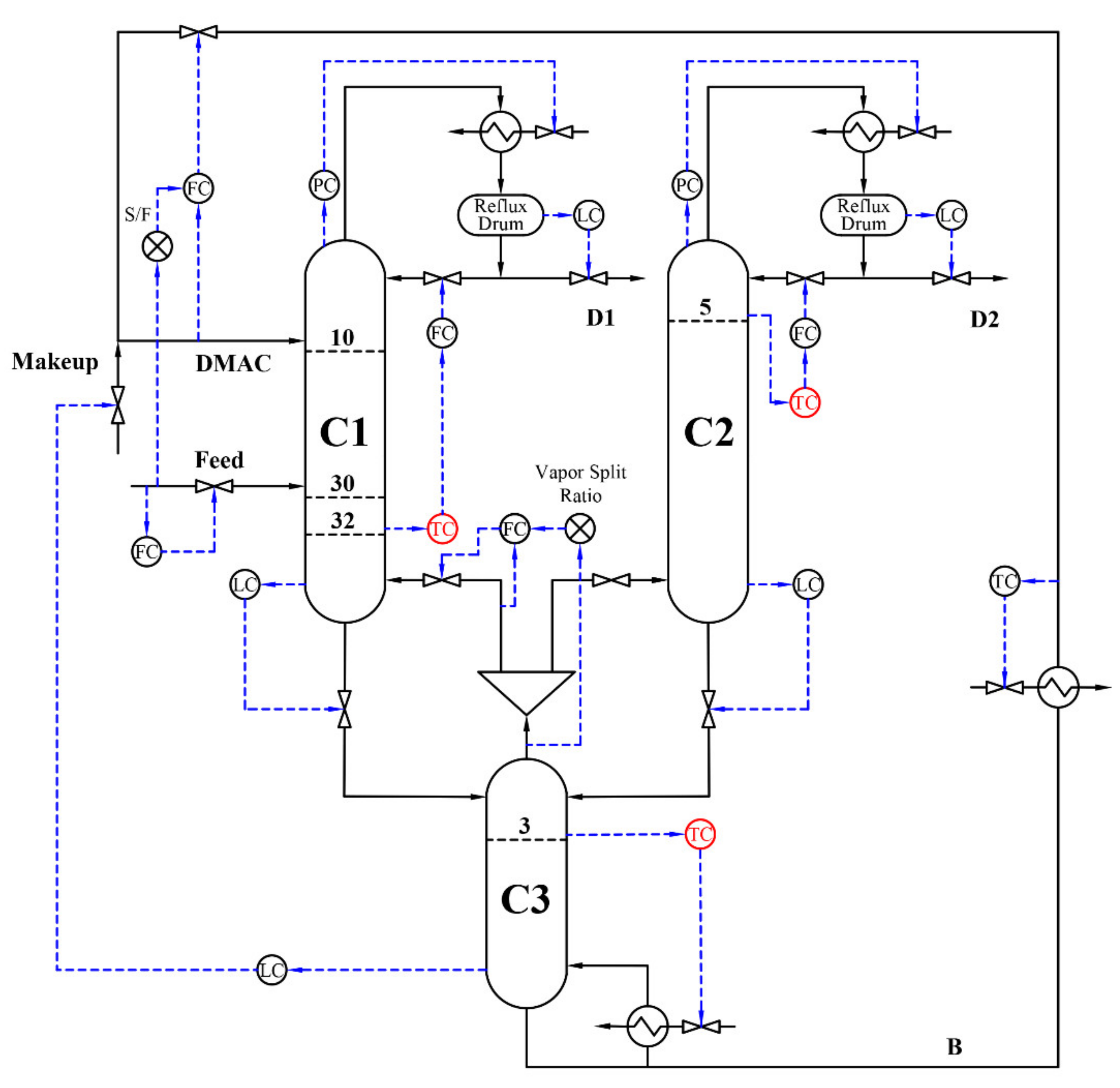
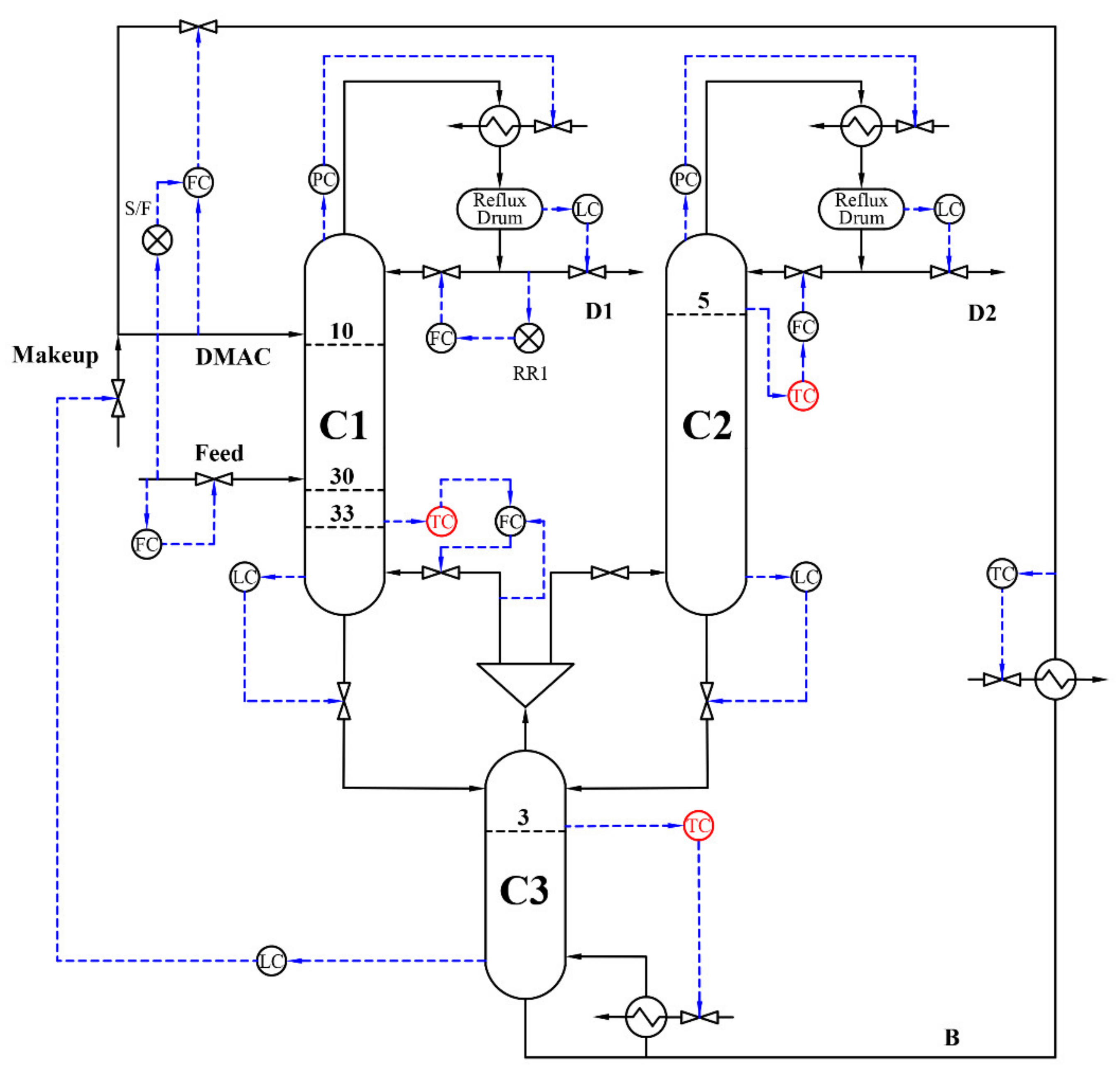
3.2. Control Structure CS1

After completing the selection of the temperature control tray, the control structure CS1 was proposed. Figure 10 shows the control structure CS1. The control loops are as follows:
  • The feed is controlled by flow (reverse acting).
  • The flow rate of the entrainer DMAC is controlled by flow (reverse acting), which is cascaded with a fixed ratio of the feed.
  • The pressure at the top is controlled by the condenser heat removal rate (reverse acting).
  • The reflux drum liquid level of the C1 and C2 columns is held by the withdraw flow rate at the top of the column (direct acting).
  • Base level in the C3 column is held by entrainer makeup flow rate (reverse acting).
  • The temperature of stage 32 in the C1 column and the temperature of stage 5 of the C2 column are controlled by manipulating the corresponding reflux ratios RR1 and RR2 (direct acting).
  • The temperature of stage 4 in the C3 column is controlled by manipulating the reboiler duty QR (reverse acting).
  • Add 1 min deadtime to all temperature control loops.
Proportional integral (PI) control was applied to all control loops. All liquid level control loops use proportional control within gain Kc = 2. The pressure controller uses proportional integral control, gain Kc = 20, integral time τ = 12 min. The gain of the flow controller was Kc = 0.5, and the integral time τ = 0.3 min. The temperature control loops with dead time obtained the corresponding control parameters through relay-feedback and Tyreus–Luyben tuning. The final tuning parameters are summarized in Table 2.
The dynamic performance of the control structure CS1 was evaluated by introducing feed flow rate and composition disturbances. Figure 11a illustrates the dynamic responses of EDWC due to ±20% disturbances in the feed. Apparently, the product purities (XD1 of the DPE and XD2 of the PA product) recover to their design values after approximately 4 h.
Figure 11b describes the dynamic responses of EDWC due to ±10% disturbances in the feed composition, with a proportional adjustment in the other components. Obviously, the purity of DPE and PA is stable and qualified at 9 h, it takes a long time to reach the new steady state. The reason is that there will be liquid hydraulic lags (3~6 s/tray) when the liquid flows through the tray, and the temperature control tray of the C1 column is stage 32 at the bottom of the column. When the temperature of the control tray is adjusted by the reflux ratio, it will produce a significant delay time, a large amount of DPE enters the C3 column, and is finally withdrawn from the top of C2 column. This leads to a large decrease in the purity of the PA product in a short time. The control structure CS1 needs to be further optimized to obtain a better dynamic performance.

3.3. Control Structure CS2

The C1 column does not have a reboiler, but there is a vapor stream V1 returning from the C3 column, and the temperature control tray of the C1 column is at the bottom. In order to reduce the impact of liquid hydraulic lags caused by the reflux ratio control of the C1 column on the dynamic control performance, adjusting the temperature control tray of the C1 column was considered, by controlling the return vapor flow rate V1 to improve the dynamic control performance.
Figure 12a shows the corresponding steady-state gains of the C1 and C3 columns when the vapor split ratio α and the heat duty QR were used as manipulated variables. Figure 12b depicts the corresponding values of the U from singular value decomposition analysis, where the U5 largest magnitude represented by the solid line appeared at stage 43 and the corresponding manipulated variable was the vapor split ratio α. The C3 column is controlled by the heat duty of the reboiler, and the vapor split ratio replaces the reflux ratio RR1 to control C1 column, so stage 33 was chosen as the control tray. The U6 largest magnitude represented by the dashed line appeared at stage 43, and the corresponding manipulated variable was QR. Therefore, the final vapor split ratio α controls the temperature of stage 33 of the C1 column, and the reboiler heat duty QR controls the temperature of stage 3 of the C3 column. The control tray location and manipulated variable of the C2 column were the same as the CS1.
The control structure CS2 is depicted in in Figure 13. The temperature control tray of the C1 column is adjusted by controlling the valve opening of the vapor stream V1. The reflux ratio RR1 uses a fixed ratio, and the temperature control loops with dead time obtain corresponding new control parameters through relay-feedback and Tyreus–Luyben tuning. The final tuning parameters are summarized in Table 3.
Figure 14a shows the dynamic responses of EDWC when facing ±20% disturbances in feed flow rate. The purity of the DPE product returned to its steady states and recovered its designed values about 2.5 h after feed flow rates changed. The purity of the PA product also stabilized at 2.5 h. The PA product purity stable value was 0.9988 only when the feed flow rate increased by 20%, which was slightly lower than the set value in a new steady state.
Figure 14b shows the dynamic responses of EDWC due to ±10% disturbances of the concentration of DPE in the feed composition. Apparently, the product purity of DPE and PA recover their design values. Furthermore, less transient oscillations and a smaller offset were observed with shorter settling times. Obviously, the dynamic control performance of CS2 was superior to that of CS1 in terms of purity control of DPE and PA under feed composition disturbances. This is mainly because when the feed composition changes, it first affects the C1 column, then affects the C3 column, and finally affects the C2 column. When the vapor split ratio is used to control the temperature of the control tray in the C1 column, the response time is more rapid, hence, the purity of the DPE product quickly stabilizes. Most of the DPE is withdrawn from the top of the C1 column, only a small amount of DPE enters the C3 and C2 columns, so the product of PA purity fluctuation is smaller and the settling time is shorter.

4. Conclusions

In this work, DMAC was selected as the entrainer to separate the dipropyl ether/1-propyl alcohol azeotropic mixture. Three sequences including CEDS, EDWC and PSDS were designed and optimized. The results show that the EDWC with DMAC as the entrainer is more economically attractive than the CEDS and the PSDS. Compared with the CEDS, the EDWC can save 12.45% of the capital investments, 10.38% of the operating costs, and 11.01% of TAC. Compared with the PSDS, the EDWC can save 41.49% of the capital investments, 47.07% of operating costs, 45.50% of TAC. Therefore, it is more economical to separate dipropyl ether/1-propyl alcohol azeotropic mixture by EDWC. This study provides technical support for the separation design of such azeotropes.
Consequently, the control structure CS1 based on a three-temperature control loop and the control structure CS2 with vapor split ratio as the manipulated variable are proposed for EDWC. The dynamic control performance of the two control structures was investigated with feed flow rate and composition disturbances. The results show that CS1 has good performance, but the transient deviation is relatively large and the settling time is too long when facing the feed flow composition disturbance. CS2 with the vapor split ratio as the manipulated variable can more effectively deal with the feed flow rate and composition disturbances. It can quickly and effectively maintain the two products at high purity. Therefore, the CS1 can be used in industry to achieve good performance. As research continues on vapor split ratio in the chemical industry, the CS2 could further improve the dynamic performance of EDWC in the future.

Author Contributions

Conceptualization, Q.Y.; methodology, Y.W.; software, Y.W.; validation, Q.Y. and W.Z.; writing—original draft preparation, Y.W.; writing—review and editing, Q.Y. and H.P.; visualization, Y.W.; supervision, P.Y. All authors have read and agreed to the published version of the manuscript.

Funding

This research received no external funding.

Institutional Review Board Statement

Not applicable.

Informed Consent Statement

Not applicable.

Data Availability Statement

Not applicable.

Acknowledgments

This work was financially supported by the National Natural Science Foundation of China [Nos. 22178113].

Conflicts of Interest

The authors declare no conflict of interest.

References

  1. Sakuth, M.; Mensing, T.; Schuler, J.; Heitmann, W.; Strehlke, G.; Mayer, D. Ethers, Aliphatic; Wiley-VCH Verlag GmbH & Co. KGaA: Weinheim, Germany, 2010. [Google Scholar]
  2. Walther, T.; Francois, J.M. Microbial production of propanol. Biotechnol. Adv. 2016, 34, 984–996. [Google Scholar] [CrossRef] [PubMed]
  3. Lladosa, E.; Montón, J.B.; Burguet, M. Separation of di-n-propyl ether and n-propyl alcohol by extractive distillation and pressure-swing distillation: Computer simulation and economic optimization. Chem. Eng. Process. 2011, 50, 1266–1274. [Google Scholar] [CrossRef]
  4. Mangili, P.V. Thermoeconomic and environmental assessment of pressure-swing distillation schemes for the separation of di-n-propyl ether and n-propyl alcohol. Chem. Eng. Process. 2020, 148, 107816. [Google Scholar] [CrossRef]
  5. Luo, H.; Liang, K.; Li, W.; Li, Y.; Xia, M.; Xu, C. Comparison of pressure-swing distillation and extractive distillation methods for isopropyl alcohol/diisopropyl ether separation. Ind. Eng. Chem. Res. 2014, 53, 15167–15182. [Google Scholar] [CrossRef]
  6. You, X.; Rodriguez-Donis, I.; Gerbaud, V. Low pressure design for reducing energy cost of extractive distillation for separating diisopropyl ether and isopropyl alcohol. Chem. Eng. Res. Des. 2016, 109, 540–552. [Google Scholar] [CrossRef] [Green Version]
  7. Yildirim, Ö.; Kiss, A.A.; Kenig, E.Y. Dividing wall columns in chemical process: A review on current activities. Sep. Purif. Technol. 2011, 80, 403–417. [Google Scholar] [CrossRef]
  8. Dejanović, I.; Matijašević, L.; Olujić, Ž. Dividing wall column-A breakthrough towards sustainable distilling. Chem. Eng. Process. 2010, 49, 559–580. [Google Scholar] [CrossRef]
  9. Buitimea-Cerón, G.A.; Hahn, J.; Medina-Herrera, N.; Jiménez-Gutiérrez, A.; Loredo-Medrano, J.A.; Tututi-Avila, S. Dividing-Wall Column Design: Analysis of Methodologies Tailored to Process Simulators. Processes 2021, 9, 1189. [Google Scholar] [CrossRef]
  10. Chen, Z.; Agrawal, R. Classification and Comparison of Dividing Walls for Distillation Columns. Processes 2020, 8, 699. [Google Scholar] [CrossRef]
  11. Wu, Y.C.; Hsu PH, C.; Chien, I.L. Critical assessment of the energy-saving potential of an extractive dividing-wall column. Ind. Eng. Chem. Res. 2013, 52, 5384–5399. [Google Scholar] [CrossRef]
  12. Xia, M.; Yu, B.; Wang, Q.; Jiao, H.; Xu, C. Design and control of extractive diving-wall column for separating methylal-methanol mixture. Ind. Eng. Chem. Res. 2012, 51, 16016–16033. [Google Scholar] [CrossRef]
  13. Xia, M.; Xin, Y.; Luo, J.; Li, W.; Shi, L.; Min, Y.; Xu, C. Temperature control for extractive diving-wall column with an adjustable vapor split: Methylal/methanol azeotrope separation. Ind. Eng. Chem. Res. 2013, 52, 17996–18013. [Google Scholar] [CrossRef]
  14. Zhang, H.; Ye, Q.; Qin, J.; Xu, H.; Li, N. Design and control of extractive dividing-wall column for separating ethyl acetate-isopropyl alcohol mixture. Ind. Eng. Chem. Res. 2014, 53, 1189–1205. [Google Scholar] [CrossRef]
  15. Dwivedi, D.; Strandberg, J.P.; Halvorsen, I.J.; Preisig, H.A.; Skogestad, S. Active vapor split control for dividing-wall columns. Ind. Eng. Chem. Res. 2012, 51, 15176–15183. [Google Scholar] [CrossRef]
  16. Huaqiang, G.; Xiangwu, C.; Nan, C.; Wenyi, C. Experimental study on vapor splitter in packed divided wall column. J. Chem. Technol. Biot. 2016, 91, 449–455. [Google Scholar] [CrossRef]
  17. Li, C.; Li, J.; Li, D.; Ma, S.; Li, H. Experimental study and CFD numerical simulation of an innovative vapor splitter in dividing wall column. AIChE J. 2020, 66, e16266. [Google Scholar] [CrossRef]
  18. Harvianto, G.R.; Kim, K.H.; Kang, K.J.; Lee, M. Optimal operation of a dividing wall column using an enhanced active vapor distributor. Chem. Eng. Res. Des. 2019, 144, 512–519. [Google Scholar] [CrossRef]
  19. Kang, K.J.; Harvianto, G.R.; Lee, M. Hydraulic driven active vapor distributor for enhancing operability of dividing wall column. Ind. Eng. Chem. Res. 2017, 56, 6493–6498. [Google Scholar] [CrossRef]
  20. Hu, Y.; Chen, S.; Li, C. Numerical research on vapor splitter in divided wall column. Chem. Eng. Res. Des. 2018, 138, 519–532. [Google Scholar] [CrossRef]
  21. Luyben, W.L. Vapor split manipulation in extractive divided-wall distillation columns. Chem. Eng. Process. 2018, 126, 132–140. [Google Scholar] [CrossRef]
  22. Jing, C.; Zhu, J.; Dang, L.; Wei, H. Extractive dividing-wall column distillation with a novel control structure integrating pressure swing and pressure compensation. Ind. Eng. Chem. Res. 2021, 60, 1274–1289. [Google Scholar] [CrossRef]
  23. Zhu, J.; Jing, C.; Hao, L.; Wei, H. Insight into controllability and operation of extractive dividing-wall column. Sep. Purif. Technol. 2021, 263, 118362. [Google Scholar] [CrossRef]
  24. Araújo Neto, A.P.; Farias Neto, G.W.; Neves, T.G.; Ramos, W.B.; Brito, K.D.; Brito, R.P. Changing product specification in extractive distillation process using intelligent control system. Neural Comput. Appl. 2020, 32, 13255–13266. [Google Scholar] [CrossRef]
  25. De Araújo Neto, A.P.; Sales, F.A.; Brito, R.P. Controllability comparison for extractive dividing-wall columns: ANN-based intelligent control system versus conventional control system. Chem. Eng. Process. 2021, 160, 108271. [Google Scholar] [CrossRef]
  26. Rewagad, R.R.; Kiss, A.A. Dynamic optimization of a dividing-wall column using model predictive control. Chem. Eng. Sci. 2012, 68, 132–142. [Google Scholar] [CrossRef]
  27. Rodriguez, M.; Li, P.Z.; Diaz, I. A control strategy for extractive and reactive dividing wall columns. Chem. Eng. Process. 2017, 113, 14–19. [Google Scholar] [CrossRef]
  28. Feng, Z.; Shen, W.; Rangaiah, G.P.; Dong, L. Proportional-integral control and model predictive control of extractive dividing-wall column based on temperature differences. Ind. Eng. Chem. Res. 2018, 57, 10572–10590. [Google Scholar] [CrossRef]
  29. Feng, Z.; Shen, W.; Rangaiah, G.P.; Dong, L. Closed-loop identification and model predictive control of extractive dividing-wall column. Chem. Eng. Process. 2019, 142, 107552. [Google Scholar] [CrossRef]
  30. Lladosa, E.; Montón, J.B.; Burguet, M.C.; Munoz, R. Phase equilibria involved in extractive distillation of dipropyl ether + 1-propyl alcohol using N, N-dimethylformamide as entrainer. J. Chem. Eng. Data 2007, 52, 532–537. [Google Scholar] [CrossRef]
  31. Luyben, W.L. Distillation Design and Control Using Aspen Simulation; John Wiley & Sons: Hoboken, NJ, USA, 2006. [Google Scholar]
  32. Luyben, W.L. Evaluation of criteria for selecting temperature control trays in distillation columns. J. Process Control 2006, 16, 115–134. [Google Scholar] [CrossRef]
  33. Qian, X.; Liu, R.; Huang, K.; Chen, H.; Yuan, Y.; Zhang, L.; Wang, S. Comparison of Temperature Control and Temperature Difference Control for a Kaibel Dividing Wall Column. Processes 2019, 7, 773. [Google Scholar] [CrossRef] [Green Version]
  34. Ling, H.; Luyben, W.L. Temperature control of the BTX divided-wall column. Ind. Eng. Chem. Res. 2010, 49, 189–203. [Google Scholar] [CrossRef]
Figure 1. (a) Process flowsheet of EDWC and (b) equivalent two column model of EDWC.
Processes 10 00665 g001
Figure 2. Effect of entrainer flow rate S and reflux ratio RR1 on the purity of DPE.
Processes 10 00665 g002
Figure 3. Process flow diagram of the CEDS.
Processes 10 00665 g003
Figure 4. Sequential iterative optimization procedure for EDWC.
Processes 10 00665 g004
Figure 5. (a) Effect of NT1 on the TAC (b) effect of NT2 on the TAC.
Processes 10 00665 g005
Figure 6. Optimal process flow diagram of the EDWC.
Processes 10 00665 g006
Figure 7. Variation of stage number and heat duty as a function of the reflux ratio for the C1 (a) and C2 (b).
Processes 10 00665 g007
Figure 8. Process flow diagram of the PSDS.
Processes 10 00665 g008
Figure 9. (a) Steady-state gains (b) SVD analysis for CS1.
Processes 10 00665 g009
Figure 10. Control structure CS1.
Processes 10 00665 g010
Figure 11. Dynamics responses of CS1 (a) 20% feed flow rate disturbances, (b) 10% feed composition disturbances.
Processes 10 00665 g011
Figure 12. (a) Steady-state gains (b) SVD analysis for CS2.
Processes 10 00665 g012
Figure 13. Control structure CS2.
Processes 10 00665 g013
Figure 14. Dynamic responses of CS2 (a) 20% feed flow rate disturbances, (b) 10% feed composition disturbances.
Processes 10 00665 g014
Table 1. Optimization results of CEDS, EDWC and PSDS.
ParameterCEDSEDWCPSDS
NT1405216
NT2254017
RR11.2001.1011.508
RR20.9000.2730.897
ID1 (m)1.1291.3602.404
ID2 (m)0.896-1.680
Total condenser duty (kW)206416586812
Total reboiler duty (kW)316928407076
Capital investment (103/yr)1305.7391143.2391953.945
Operation cost (103/yr)987.304884.8741671.689
TAC (103/yr)1422.5511265.9552323.004
Table 2. Tuning parameters of temperature controllers in CS1.
ParameterTC1TC2TC3
Controlled variableC1-T32C2-T5C3-T3
Manipulated variableRR1RR2QR
Gain, Kc1.3945.1971.302
Integral time/min40.9213.2013.20
Table 3. Tuning parameters of temperature controllers in CS2.
ParameterTC1TC2TC3
Controlled variableC1-T33C2-T5C3-T3
Manipulated variableV1RR2QR
Gain, Kc6.0137.0231.316
Integral time/min9.2411.8811.88
Publisher’s Note: MDPI stays neutral with regard to jurisdictional claims in published maps and institutional affiliations.

