Article

Low-Temperature Joining of B4C Ceramics Using Cold-Sprayed Al-8wt%Si Alloy and Microstructure of the Vicinity of the Joint Interface

1
Department of Chemical Systems Engineering, Graduate School of Engineering, Nagoya University, Furo-cho, Chikusa-ku, Nagoya 464-8603, Japan
2
Department of Materials Process Engineering, Graduate School of Engineering, Nagoya University, Furo-cho, Chikusa-ku, Nagoya 464-8603, Japan
*
Author to whom correspondence should be addressed.
Processes 2022, 10(12), 2573; https://doi.org/10.3390/pr10122573
Submission received: 29 October 2022 / Revised: 24 November 2022 / Accepted: 29 November 2022 / Published: 2 December 2022
(This article belongs to the Section Materials Processes)

Abstract

:
A series of studies were conducted to demonstrate the feasibility of low-temperature bonding by the forming and heating an Al-8wt%Si alloy thick film on a B4C surface by cold spraying. The results show that: (1) The cracks near the joining interface are closed by the Al alloy by the process studied in this study, and a joining strength of about 220 and 240 MPa is achieved by low temperature joining of 580 °C and 600 °C, respectively.; (2) The amount of weak intermetallic compounds at the joining interface is reduced; (3) It is assumed that the reduction in the amount of Al-B-C compounds is due to the formation of the β phase during the solidification process of the Al-Si alloy, which hinders the growth of the compounds.; (4) On the primary joint surface, a continuous void group is formed in the vicinity of the β phase that surrounds the α phase, causing a decrease in the joining strength.

1. Introduction

Boron carbide (B4C) is known as a ceramic material with light specific gravity, a high Young’s modulus and hardness, good wear resistance, excellent neutron absorption capacity, and electrical conductivity. These characteristics are expected to be utilized in many fields such as sliding materials, semiconductor manufacturing equipment, nuclear power system components, protection components, and thermoelectric devices [1,2,3,4,5,6,7,8,9,10,11,12,13,14,15,16,17]. B4C is inherently difficult to sinter and has been previously sintered by hot-pressing. In recent years, dense sintered bodies have been obtained using pressureless sintering and boron carbide ceramic parts with complex shapes can now be produced using injection molding followed by sintering [18]. Among the applications that take advantage of the features of B4C, wafer stages for semiconductors are considered particularly important because they are essential for manufacturing high-precision semiconductors. However, due to their large size, the wafer stages must be manufactured in sections that are then joined. In this regard, Sekine et al. obtained high-strength joints by sandwiching Al foil between two B4C, clamping the sandwich assembly together, and then heating it to 1000 °C in a vacuum [19,20]. The joints consist of two distinct regions: a primary joint of Al, Al3BC, or AlB2 and Al4C3 compounds formed by the reaction between aluminum and B4C, and a region of nanoscale composites extending approximately 30 µm from the joint where aluminum penetrated the B4C cracks and spread in a network structure [19,20].
In a related study, Gou et al. observed the morphology and composition of the network structure formed at the B4C–Al interface in detail using transmission electron microscopy and energy-dispersive X-ray spectroscopy. They confirmed that compounds are difficult to form inside narrow cracks and that the penetrated Al tends to remain pure. They also conducted a thermodynamic study on the formation mechanism [21]. In a study by Sekine et al., relatively high strength was obtained during the joining of B4C. However, the joining temperature was still as high as 1000 °C. In the case of parts used at room temperature, high-temperature joining is unnecessary, and it is desirable to keep the joining temperature as low as possible to save energy. Additionally, the compounds formed at the interface are fragile. When B4C is joined using Al, various intermetallic compounds are produced by the reaction [22,23,24], and it has been reported that one of these compounds, Al4C3, is brittle and unstable [25,26]. To overcome these problems, we selected a well-known Al-Si alloy as the insert material. The use of this alloy lowered the melting point by mixing the two components. When cooled from the molten state, a Si-rich β phase precipitated to form a double-phase structure [27]. The use of Al-Si alloys in B4C joints has two implications. The first is the lowering of the joint temperature, and the second is the suppression of the growth of Al-C and Al-B-C compounds due to the β-phase formation. Many studies have been reported on the use of Al-Si alloys or Al as a joining material for joining ceramics such as SiC [26,28,29,30,31,32,33,34,35,36]. Among them, Chen et al., for example, used Al-12Si for joining SiC and obtained a strength of 94 MPa by ultrasonic-assisted joining at 620 °C in air [26]. However, to the best of our knowledge, no studies have been reported on the use of Al-Si alloy as the joining material for B4C and the investigation of the properties and interface structure formation of the obtained joining body.
The novelties of this study are to (1) clarify the process and conditions that enable the joining of B4C at low temperatures below 600 °C and obtain high strength; (2) select the cold spray method, which has rarely been reported for joining, and devise the formation of a thick film of Al-Si alloy adhered to the B4C surface; and (3) clarify the mechanism of B4C joint interface formation when an Al-Si alloy is used as an joint material by examining the microstructure details after joining.
Based on the above, the purpose of this study is, first, to demonstrate the formation of the Al-8wt%Si alloy thick film on the B4C surface by the cold spray method, the possibility of molten Al-Si penetration into the cracks during joining, and the possibility of obtaining high strength using B4C specimens joined at a low temperature of approximately 580 °C. At the same time, we will investigate the mechanism of phase formation of the Al-Si alloy during penetration and solidification in the microcracks of B4C.

2. Materials and Methods

2.1. Sample Preparation

The B4C ceramics used in the tests were purchased from Mino Ceramic Co., Ltd. (Nagoya, Aichi, Japan). Its bulk density is 2.4 g/cm3, bending strength is 350 MPa, Young’s modulus is 410 GPa, fracture toughness value KIc is 3.5 MPa·m1/2, and thermal conductivity is 30 W/m·K [37]. The ceramics were cut into plates with dimensions of 20 mm × 25 mm × 5 mm and subjected to joining tests. One end face (25 × 5 mm face) was ground to a roughness (Ra) of approximately 0.2–0.4 μm [19,20,21]. An Al-Si alloy powder produced using the atomizing method and manufactured by Hikari Material Mfg. Co., Ltd. (Tomi, Nagano, Japan) was used as the joining material. The average particle size was 106 μm. In the preliminary test, 8, 12, 15, and 30wt% of Si was used. We found that as the Si content increased, the adhesion to the B4C substrate decreased; therefore, Al-8wt% Si was used in this study. A film-forming technology was employed, in which heated or room-temperature high-pressure gas was accelerated at an ultrahigh speed by a special nozzle. The material was accelerated by injecting a metal alloy powder into the center of the gas flow, ejected from the nozzle outlet, and collided with the base material as a solid [38]. The particles of the material that collide with the base material plastically deform along with the base material and adhere to it. In the experiment, a low-pressure cold-spray device, i.e., the advanced cold gas system manufactured by Startac Co., Ltd. (Kobe, Hyogo, Japan), was used. After forming an Al-Si alloy film (thickness of approximately 50 µm) on the B4C substrate (thickness of 5 mm) using the cold spray method, it was aligned to the coated surfaces using a carbon jig. Using an atmosphere control furnace (Fulltech Co., Ltd.; Yao, Osaka, Japan), the temperature was raised in a vacuum state to a maximum of 580 °C at a heating rate of 2.5 °C /min, and maintained for 2 h. Then, the sample was also cooled at 2.5 °C /min. For comparison, a few samples were heated under the same conditions up to 600, 650, and 1000 °C.

2.2. Evaluation

After joining, a test piece (width 4.0 ± 0.1 mm × thickness 3.0 ± 0.1 mm × total length 40 mm, according to JISR1621) was machined so that the joint surface was almost in the center. Then, a four-point bending test was performed according to the bending strength test method for fine ceramics (JISR1601). The four-point bending test was calculated using the following formula:
σ = (3P (Ll))/(2wt2)
where σ: four-point bending strength (MPa), P: maximum load when the test piece breaks [N], L: distance between external fulcrums (mm), l: distance between internal fulcrums (mm), w: width of test piece (mm), t: specimen thickness (mm). For each joining condition, a bending test was conducted with the number of samples, N = 5. The microstructure of the samples was observed and analyzed. The equipment used to prepare the samples was a Hitachi High-Technologies “nanoDUE” TNB5000 focused ion/electron beam system processing and observation equipment, and an FII Japan Nova200 focused ion/electron beam processing and observation equipment. For observation and analysis, a field emission transmission electron microscope Talos F200X manufactured by FII Japan, a camera system Ceta16M manufactured by FII Japan, and an EDX analyzer Super-X manufactured by FII Japan were used. The acceleration voltage was 200 kV, and the analysis methods (for EDX) were an area of analysis and point analysis.

3. Results

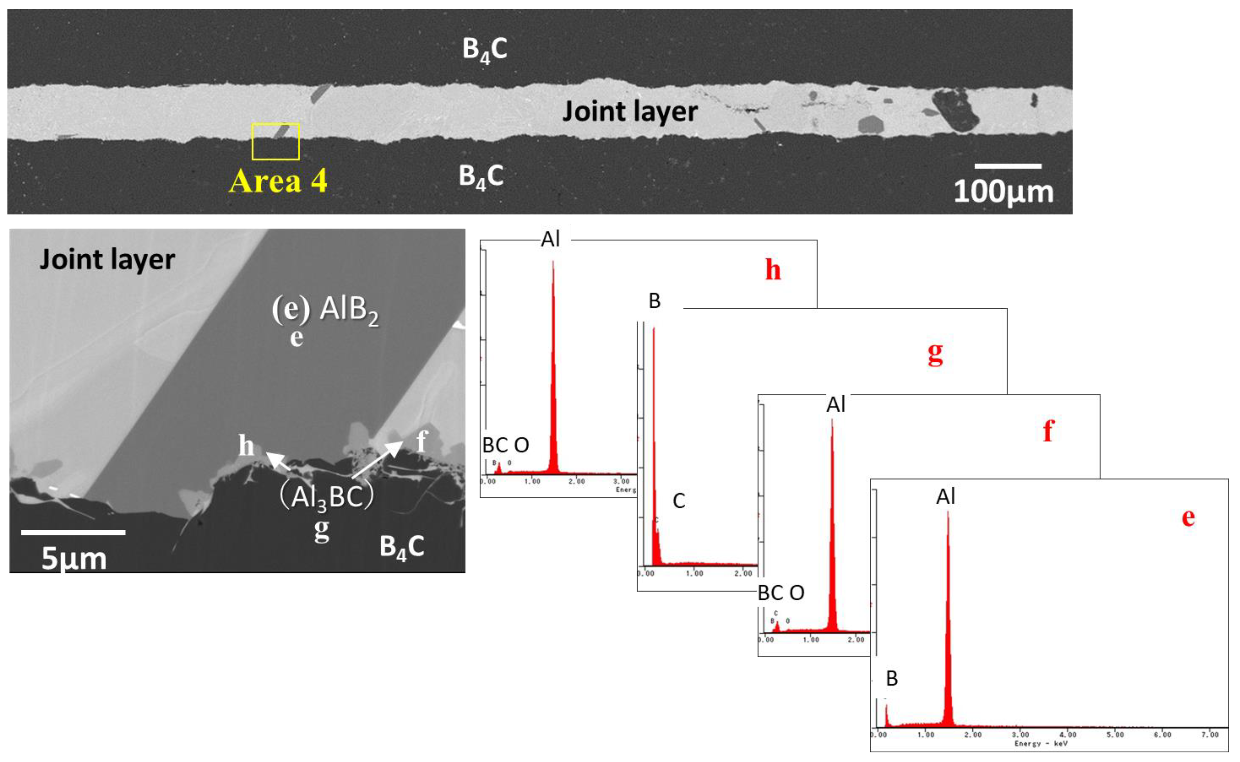
3.1. The Morphology of the Main Interface and the Formation of Compounds

The observation results of the surface and cross-section analyses after the formation of a thick Al-Si alloy film on the surface of the B4C substrate by cold spraying are shown in Figure 1. It appears that the film is dense and has good adhesion to the substrate with a thickness of approximately 50 μm.
The advantage of cold spraying is that alloys of any composition can be formed densely and efficiently. In this study, when cold spraying is performed using Al-Si alloy powder having a different Si compounding ratio, it is found that peeling occurred more easily as the amount of Si increased. This is because Si has lower ductility than Al. Based on these results, we selects Al-8wt% Si, which has good workability, for further experimentations. Another B4C plate was placed on the surface, where the thick alloy film was formed by cold spraying, fixed to a carbon jig, and heated above the melting point of the Al-Si alloy used as the joining material. Using this process, a jointed test piece with an Al-Si alloy film as the intermediate layer is obtained. The structure of the sample after joining with an Al-8wt% Si film, which is used as the insert material heated at 580 °C, is shown in Figure 2.
Sample description: A8S580, in which “A” indicates Al, “8S” indicates that the Si compounding ratio is 8wt%, and “580” indicates the heat treatment temperature (in °C). The main joint surface of A8S580 has two large contrasts: the β phase that appears as an island and the α phase (primary crystal) that surrounds the β phase. Furthermore, Figure 3 shows the Al-Si phase diagram and positioning of the test conditions in this study. In the case of Al-8wt%Si, the liquid phase and primary crystal α coexists at 580 °C. Furthermore, at 577 °C, the Al-rich α and β phases, which are almost Si, precipitate.
A lamellar structure, in which the α and β phases that are peculiar to the eutectic composition are arranged in stripes, is observed in places other than the primary crystal α. Based on the results shown in Figure 2, it should be noted that the Al-B-C compound is not formed on the main-joining surface. For comparison, Figure 4 shows the cross-sectional images of the joint surface of a sample, in which the B4C ceramics are bonded to each other at 1000 °C using a pure Al foil as the insert agent. This sample will henceforth be referred to as A0S1000. In this sample, a dark contrast area is observed on the main joint surface, which is confirmed to be composed of compounds such as Al, Al3BC, AlB2, and Al4C3 [19,20,21].
Comparing Figure 2 (A8S580) and Figure 4 (A0S1000), we can observe that the ridgeline of the B4C interface is smooth in A8S580, whereas A0S1000 exhibits a complicated morphology. As aforementioned, almost no Al-B-C compounds are observed on the main-joining surface of A8S580. The free energy of the reaction, in which the intermetallic compound is formed from Al and B4C, is negative over a wide temperature range (Figure 5), and the reaction proceeds to the right even at 580 °C.
(5/3)Al (l) + B4C (s) → (1/3)AlB12 (s) + (1/3)Al4C3 (s) ΔG = −80 kJ/mol.
(10/3)Al (l) + B4C (s) → 2AlB2 (s) + (1/3)Al4C3 (s) ΔG = −276 kJ/mol
As can be observed from Figure 4, the unevenness of the ridgeline at the B4C interface of A0S1000 is severe because B4C was eroded by the contacting molten Al and incorporated into Al. The compounds that are present on the main-joining surface, produced by the reaction between B4C and Al, are also incorporated into the Al layer. In contrast, in A8S580, the Al-B-C compound is hardly produced, the morphology of the interface portion of B4C is smooth, and the state before joining is almost maintained. However, when the interface of A8S580 is analyzed in more detail, we find that small crystals with a size of 1 μm or less grow at the B4C interface (Figure 6). There are several possible reasons for which the compound does not grow significantly in A8S580 as compared to A0S1000. First, considering the reaction kinetics, when Si is dissolved in the solution, the activity of Al in the solution reduces as the movement is suppressed. Furthermore, the growth rate slows down because the heat treatment temperature is lower.
Another reason is that the β phase, which previously precipitates during the cooling process, impedes the growth of the Al-B-C compound. In other words, the β phase is formed first, and the growth of the Al-B-C compound, which nucleates at the B4C interface, is suppressed. Therefore, after the formation of the Al-8wt% Si film, heat treatment was performed at 1000 °C (A8S1000), and the structure was analyzed. The results are shown in Figure 7. The SEM image at the bottom left of Figure 7 shows dark coarse particles that grow in the columns of the B4C region. The EDX analysis of point e reveals that the coarse particle is AlB2. Furthermore, the e phase with a thickness of approximately 1 µm, generated on the B4C side (point g) of the coarse particle, is also a reflection image of points f and h. Based on the contrast, it is considered to be Al3BC. The contrast at point e is darker than those at points f and h because the concentration of B, which is a light element, is higher, as indicated by the SEM reflection image. The production of coarsened compounds is also observed in A8S1000.
However, the amount of compound produced is smaller than that produced in A0S1000, even when treated at the same temperature. The compound that is produced in A0S1000 by the β phase, which is generated earlier, is suppressed in A8S1000. It is highly probable that most of the low-temperature A8S580 underwent nucleation at the B4C interface and grows into fine crystal grains.

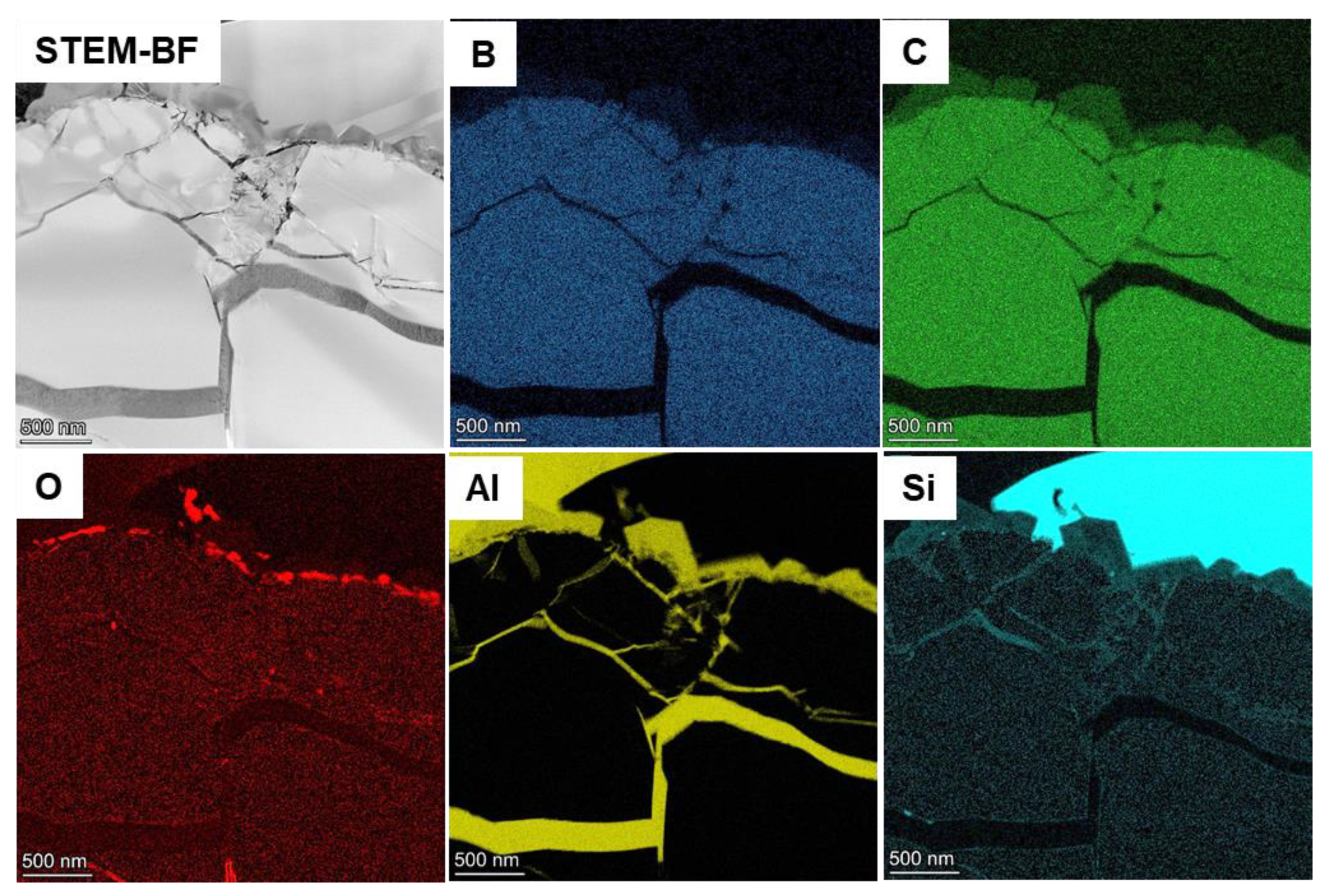
3.2. Penetration into Cracks and Their Composition

Figure 8 shows the permeation status of the Al-8wt%Si alloy into fine cracks extending from the main joint surface ofA8S580. As previously reported, in A0S1000, Al penetrates the tip of the interior of a fine crack, resulting in a closed-crack structure [19,20,21]. When pure Al is used, even if the sample is heat-treated at 580 °C, it does not melt because it is below the melting point of pure Al (660 °C). Therefore, the metal does not penetrate the cracks. In the case of A8S580, it is found that the molten Al-8wt%Si alloy can still penetrate the crack because it partially formed a liquid phase. However, as shown in Figure 8 (right-side image), cavities are observed inside the fine cracks. The penetration is significantly affected by the amount of liquid phase in the alloy. When the amount of the liquid phase is insufficient, it cannot wet and spreads on the B4C surface or in the fine cracks, and thus, the molten Al cannot penetrate the fine cracks.
The top left image in Figure 9 shows the concentration mapping of B, C, O, Al, and Si in the crack extending from the main joint surface of A8S580. The upper part of the scanning transmission electron microscopy bright field (STEM-BF) image that corresponds to the concentration mapping of Si shows an Si-rich β phase. Looking at the inside of the crack extending from the α phase in the upper left of the STEM-BF image to B4C, it can be seen that Si is dispersed near the entrance and the interior of the crack is Si-deficient.
The structure is investigated at higher magnification, and the results are presented in Figure 10, Figure 11 and Figure 12. The table shows the results of the anti-quantitative analysis by EDX at the measurement points in Areas #1–#6. Although its amount fluctuated, Si existed in Areas #1–#4. However, Si is not detected in Area#5, which is consistent with the concentration mapping result shown in Figure 9. It can be observed that most Si is found at the crack entrance and there is less Si inside the cracks extending from the main joint surface. A region with dark contrast is observed at Point 6 of Area # inside the crack (Figure 11). Figure 12 shows a higher magnification of this section. A phase different from the surroundings is formed in this region, and it exists near the B4C interface as a phase with 25.6% Si (at point 2 in Figure 11), which is considerably higher than the original average Si content (8%) of the Al-Si alloy.

3.3. Joining Strength

Figure 13 shows the bending strengths of A8S580, A8S600, and A8S650, in which Al-8wt% Si was used as the insert agent and the joining temperatures were 580, 600, and 650 °C, respectively. All of these, even the A8S580 sample, which is joined at the lowest temperature of 580 °C, show good joining strength of approximately 220 MPa. At a joining temperature of 600 °C, the strength is approximately 240 MPa. This is because Al penetrated the cracks inside B4C and joined strongly owing to the anchor effect, as described in the previous observation results, even at low joining temperatures. As the temperature increases, the joint remains undamaged, and the base metal other than the joint broke. Most of the A8S580 sample ruptures at the joints. The seed joint surface of A8S580 shows a β phase extending in a columnar shape around the α phase of the primary crystal; however, voids tend to remain in the vicinity of this β phase. A continuous void group is formed and surrounded the α phase (Figure 14). Hence, the strength of A8S580 decreases because of these voids, which act as fracture origins.

4. Conclusions

A series of experiments were conducted with the aim of lowering the joining temperature of B4C and suppressing the formation of Al-B-C compounds at the joining interface, and the following conclusions are drawn.
(1)
The amount of Al-B-C compounds at the joint interface can be reduced by heating at 580 °C in vacuum, followed by the formation of an Al-8wt% Si alloy thick film on the B4C surface using the cold spray method.
(2)
The cracks near the joint interface are sealed with an Al alloy, and joining strength of approximately 220 MPa (joined at 580 °C) and 240 MPa (joined at 600 °C) is achieved.
(3)
It is assumed that the reduction in the amount of Al-B-C compounds is due to the formation of the β phase during the solidification process of the Al-Si alloy, which hinders the growth of the compounds.
(4)
On the main joint surface, a continuous void group, which causes a decrease in the strength, is formed in the vicinity of the β phase that surrounds the α phase.

Author Contributions

Conceptualization, H.K. and R.G.; methodology, R.G., S.Y. and H.K.; validation, H.K., S.Y. and R.G.; formal analysis, H.K.; investigation, H.K., R.G. and S.Y.; resources, H.K.; writing—original draft preparation, H.K.; writing—review and editing, H.K., S.Y. and R.G.; supervision, H.K.; funding acquisition, H.K. All authors have read and agreed to the published version of the manuscript.

Funding

This work was supported by the JST (Japan Science and Technology Agency)-OPERA (Program on Open Innovation Platform with Enterprises, Research Institute and Academia), Grant JPMJOP1843 as part of the Innovative Development of Ceramics Production Technology for Energy Saving project.

Institutional Review Board Statement

Not applicable.

Informed Consent Statement

Not applicable.

Data Availability Statement

Data are contained within the article.

Conflicts of Interest

The authors declare no conflict of interest.

References

  1. Baradeswaran, A. Elaya Perumal, Influence of B4C on the tribological and mechanical properties of Al 7075–B4C composites. Compos. Part B Eng. 2013, 54, 146–152. [Google Scholar] [CrossRef]
  2. Thévenot′, F.; Lugscheider, E.; Xu, R.; Indacochea, J.E. Boron carbide—A comprehensive review. J. Eur. Ceram. Soc. 1990, 6, 205–225. [Google Scholar] [CrossRef]
  3. Ganguly, C.; Roy, S.K.; Roy, P.R. A review on boron carbide. Key Eng. Mater. 1991, 56, 59–88. [Google Scholar]
  4. Avcioglu, S.; Kaya, F.; Kaya, C. Non-catalytic synthesis of boron carbide (B4C) Nano structures with various morphologies by sol–gel process. Mater. Lett. 2019, 249, 201–205. [Google Scholar] [CrossRef]
  5. Werheit, H.; Manghnani, M.H.; Kuhlmann, U.; Hushur, A.; Shalamberidze, S. Mode Grüneisen parameters of boron carbide. Solid State Sci. 2017, 72, 80–93. [Google Scholar] [CrossRef]
  6. Gunjishima, L.; Akashi, T.; Goto, T. Thermoelectric Properties of Single Crystalline B4C Prepared by a Floating Zone Method. Mater. Trans. 2001, 42, 1445–1450. [Google Scholar] [CrossRef] [Green Version]
  7. Zhang, W.; Chen, X.; Yamashita, S.; Kubota, M.; Kita, H. Tribological behaviour of B4C-SiC composite ceramics under water lubrication: Influence of counterpart. Mater. Sci. Technol. 2021, 37, 863–876. [Google Scholar] [CrossRef]
  8. Zhang, W.; Chen, X.; Yamashita, S.; Kubota, M.; Kita, H. Effect of Water Temperature on Tribological Performance of B4C-SiC Ceramics under Water Lubrication. Tribol. Lett. 2021, 69, 34. [Google Scholar] [CrossRef]
  9. Zhang, W.; Chen, X.; Yamashita, S.; Kubota, M.; Kita, H. B4C-SiC Ceramics with Interfacial Nanorelief Morphologies and Low Underwater Friction and Wear. ACS Appl. Nano Mater. 2021, 4, 3159–3166. [Google Scholar] [CrossRef]
  10. Zhang, W.; Yamashita, S.; Kita, H. A study of B4C-SiC composite for self-lubrication. J. Am. Ceram. Soc. 2021, 104, 2325–2336. [Google Scholar] [CrossRef]
  11. Zhang, W.; Yamashita, S.; Kumazawa, T.; Ozeki, F.; Hyuga, H.; Norimatsu, W.; Kita, H. A study on formation mechanisms of relief structure formed in situ on the surface of ceramics. Ceram. Int. 2019, 45, 23143–23148. [Google Scholar] [CrossRef]
  12. Zhang, W.; Yamashita, S.; Kumazawa, T.; Ozeki, F.; Hyuga, H.; Kita, H. Influence of surface roughness parameters and surface morphology on friction performance of ceramics. J. Ceram. Soc. Jpn. 2019, 127, 837–842. [Google Scholar] [CrossRef] [Green Version]
  13. Zhang, W.; Yamashita, S.; Kita, H. Progress in pressureless sintering of boron carbide ceramics—A review. Adv. Appl. Ceram. Struct. Funct. Bioceram. 2019, 118, 222–239. [Google Scholar] [CrossRef]
  14. Nakashima, H.; Ohta, M.; Nakao, Y. Nuclear Characteristics of Gas-Suspended Boron Carbide Cooling Catalyzed D Fusion Reactor Blanket. J. Nucl. Sci. Technol. 1977, 14, 916–919. [Google Scholar] [CrossRef]
  15. Gou, R.; Park, J.H.; Yamashita, S.; Hagio, T.; Ichino, R.; Kita, H. Aluminum Electrodeposition on the Surface of Boron Carbide Ceramics by Use EMIC–AlCl3 Ions Liquid. Coatings 2022, 12, 1535. [Google Scholar] [CrossRef]
  16. Kuliiev, R.; Orlovskaya, N.; Hyer, H.; Sohn, Y.; Lugovy, M.; Ha, D.G.; Radovic, M.; Castle, E.G.; Reece, M.J.; Sasikumar, P.V.W.; et al. Spark Plasma Sintered B4C—Structural, Thermal, Electrical and Mechanical Properties. Materials 2020, 13, 1612. [Google Scholar] [CrossRef] [Green Version]
  17. Domnich, V.; Reynaud, S.; Haber, R.A.; Chhowalla, M. Boron Carbide: Structure, Properties, and Stability under Stress. J. Am. Ceram. Soc. 2011, 94, 3605–3628. [Google Scholar] [CrossRef]
  18. Kumazawa, T.; Honda, T.; Zhou, Y.; Miyazaki, H.; Hyuga, H.; Yoshizawa, Y. Pressureless sintering of boron carbide ceramics. J. Ceram. Soc. Jpn. 2008, 116, 1319–1321. [Google Scholar] [CrossRef] [Green Version]
  19. Sekine, K.; Kumazawa, T.; Wu-Bian, T.; Hyuga, H.; Kita, H. Influence of joining time and temperature on the flexural strength of joined boron carbide ceramics. J. Ceram. Soc. Jpn. 2012, 120, 393–399. [Google Scholar] [CrossRef] [Green Version]
  20. Sekine, K.; Kumazawa, T.; Wu-Bian, T.; Hyuga, H.; Kita, H. Low-temperature joining of boron carbide ceramics. J. Ceram. Soc. Jpn. 2012, 120, 207–210. [Google Scholar] [CrossRef] [Green Version]
  21. Gou, R.; Yamashita, S.; Sekine, K.; Kita, H. Microstructural analysis of network-like crack structure formed at Al–B4C interface. J. Eur. Ceram. Soc. 2021, 41, 6962–6970. [Google Scholar] [CrossRef]
  22. Halverson, D.C.; Pyzik, A.J.; Aksay, I.A.; Snowden, W.E. Processing of boroncarbide-aluminum composites. J. Am. Ceram. Soc. 1989, 72, 775–780. [Google Scholar] [CrossRef] [Green Version]
  23. Pyzik, A.J.; Beaman, D.R. Al-B-C phase development and effects on mechanical properties of B4C/Al-derived composites. J. Am. Ceram. Soc. 1995, 78, 305–312. [Google Scholar] [CrossRef]
  24. Viala, J.C.; Bouix, J.; Gonzalez, G.; Esnouf, C. Chemical reactivity of aluminium with boron carbide. J. Mater. Sci. 1997, 32, 4559–4573. [Google Scholar] [CrossRef]
  25. Itatani, K.; Kishioka, A. Some Properties of Aluminum Carbide and Its Related Compounds. Inorg. Mater. 1997, 4, 633–641. [Google Scholar]
  26. Chen, X.; Xie, R.; Lai, Z.; Liu, L.; Yan, J.; Zou, G. Interfacial structure and formation mechanism of ultrasonic-assisted brazed joint of SiC ceramics with Al–12Si filler metals in air. J. Mater. Sci. Technol. 2017, 33, 492–498. [Google Scholar] [CrossRef]
  27. Ye, H. An overview of the development of Al-Si-alloy based material for engine applications. J. Mater. Eng. Perform. 2003, 2, 288–297. [Google Scholar] [CrossRef]
  28. Liu, G.; Zhang, X.; Yang, J.; Qiao, G. Recent advances in joining of SiC-based materials (monolithic SiC and SiCf/SiC composites): Joining processes, joint strength, and interfacial behavior. J. Adv. Ceram. 2019, 8, 19–38. [Google Scholar] [CrossRef] [Green Version]
  29. Iseki, T.; Yamashita, K.; Suzuki, H. Joining of Dense Silicon Carbide by Aluminum Metal. Yogyo-Kyokai-Shi 1983, 91, 11–15. [Google Scholar] [CrossRef] [Green Version]
  30. Nakahashi, M. Joining of Ceramics to Metals (1), Interfacial reactions between ceramics and metals. Yousetsu-Gakkaishi 1996, 65, 6–11. [Google Scholar] [CrossRef]
  31. Chen, C.; Suganuma, K. Low temperature SiC die-attach bonding technology by hillocks generation on Al sheet surface with stress self-generation and self-release. Sci. Rep. 2020, 10, 9042. [Google Scholar] [CrossRef] [PubMed]
  32. Yano, T.; Iseki, T. HREM Observation of Interfacial Structure Formed in SiC/Al Joint. Mater. Jpn. 1998, 37, 8. [Google Scholar] [CrossRef]
  33. Tanaka, T.; Ito, M.; Narita, T. Joining of aluminum alloys/silicon nitride ceramics with the low melting point braze of an Al–Cu–Si alloy. Keikinzoku 2005, 55, 120–124. [Google Scholar]
  34. Okamura, H.; Sakamoto, M.; Shida, T. Bonding of Silicon Carbide Ceramics by using Active Brazing Metal. (No. 1). Yousetsu Gakkai Ronbun-Syu 1990, 8, 108–115. [Google Scholar]
  35. Pan, H.; Itoh, I.; Matsubara, M. Mechanical Properties of Diffusion Bonding Joint of SiC and Al-Sn Alloys at Elevated Temperatures. Mater. Trans. 2001, 42, 2543–2547. [Google Scholar] [CrossRef] [Green Version]
  36. Ikeshoji, T.; Shuying, L.; Suzumura, A.; Yamazaki, T. Effect of Isothermal Solidification Behavior of Al-Si Brazing Filler Layer on the Braze-ability of Al-Alloy to Stainless Steel in the Air. Yousetsu Gakkai Ronbun-Syu 2006, 24, 362–367. [Google Scholar]
  37. National Institute of Advanced Industrial Science and Technology, Tanka-Houso Ceramics no Jituyoutekina Jyouatsu Syouketsu Hou Wo Kaihatsu, Press Release. 2008. Available online: https://www.aist.go.jp/aist_j/press_release/pr2008/pr20080313/pr20080313.html (accessed on 10 October 2022). (In Japanese).
  38. Diab, M.; Pang, X.; Jahed, H. The effect of pure aluminum cold spray coating on corrosion and corrosion fatigue of magnesium (3% Al-1% Zn) extrusion. Surf. Coat. Technol. 2017, 309, 423–435. [Google Scholar] [CrossRef]
Figure 1. Formation of Al-Si alloy thick film on B4C ceramics surface by cold spray method (right: observation from above, left: observation result of cross section).
Processes 10 02573 g001
Figure 2. Cross-sectional SEM observation forAl-8Si/B4C (joining temperature 580 °C). Spectra “a” and “b” on the right show the EDX spectra of points a and b shown in the left-bottom photograph.
Processes 10 02573 g002
Figure 3. Al-Si phase diagram and positioning of the test conditions in this study.
Processes 10 02573 g003
Figure 4. Cross-sectional SEM observation for Al/B4C (joining temperature 1000 °C).
Processes 10 02573 g004
Figure 5. Gibbs free energy of formation.
Processes 10 02573 g005
Figure 6. Fine phase of compounds produced around the vicinity of B4C in Al-8Si/B4C (joining temperature 1000 °C). Spectra “c” and “d” on the right show the EDX spectra of points c and d shown in the left photograph.
Processes 10 02573 g006
Figure 7. Cross-sectional SEM observation for Al-8Si/B4C (joining temperature 1000 °C). Spectra “e, f, g, h” on the right show the EDX spectra of points e, f, g, h shown in the left-bottom photograph.
Processes 10 02573 g007
Figure 8. Al-8Si/B4C (joining temperature 580 °C) and the penetration status of Al into cracks near the joint area.
Processes 10 02573 g008
Figure 9. EDX Mapping Result (Al-8Si/B4C (Joining Temperature of 580 °C)). B, C, O, Al, and Si on the right shoulder of the figure are element symbols, respectively.
Processes 10 02573 g009
Figure 10. STEM observation results of Al-8Si/B4C (joining temperature 580 °C).
Processes 10 02573 g010
Figure 11. STEM image of the phase observed around the vicinity of B4C and the EDX analysis results (Al-8%Si (Joining Temperature 580 °C)).
Processes 10 02573 g011
Figure 12. High-resolution STEM image of the phase observed at vicinity of B4C.
Processes 10 02573 g012
Figure 13. Joining strength when Al-8wt%Si is used as a joining material and the temperature is changed.
Processes 10 02573 g013
Figure 14. Voids array (upper) and its enlarged image (lower) on the main joint surface of Al-8Si/B4C (joining temperature 580 °C).
Processes 10 02573 g014
Publisher’s Note: MDPI stays neutral with regard to jurisdictional claims in published maps and institutional affiliations.

