Article

Application of Recursive Theory of Slow Viscoelastic Flow to the Hydrodynamics of Second-Order Fluid Flowing through a Uniformly Porous Circular Tube

by
Kaleemullah Bhatti
1,*,
Abdul Majeed Siddiqui
2 and
Zarqa Bano
1,*
1
Department of Mathematics and Social Sciences, Sukkur IBA University, Sukkur 65200, Sindh, Pakistan
2
Department of Mathematics, Pennsylvania State University, York Campus, York, PA 17403, USA
*
Authors to whom correspondence should be addressed.
Mathematics 2020, 8(7), 1170; https://doi.org/10.3390/math8071170
Submission received: 19 June 2020 / Revised: 11 July 2020 / Accepted: 14 July 2020 / Published: 16 July 2020

Abstract

:
Slow velocity fluid flow problems in small diameter channels have many important applications in science and industry. Many researchers have modeled the flow through renal tubule, hollow fiber dialyzer and flat plate dialyzer using Navier Stokes equations with suitable simplifying assumptions and boundary conditions. The aim of this article is to investigate the hydrodynamical aspects of steady, axisymmetric and slow flow of a general second-order Rivlin-Ericksen fluid in a porous-walled circular tube with constant wall permeability. The governing compatibility equation have been derived and solved analytically for the stream function by applying Langlois recursive approach for slow viscoelastic flows. Analytical expressions for velocity components, pressure, volume flow rate, fractional reabsorption, wall shear stress and stream function have been obtained correct to third order. The effects of wall Reynolds number and certain non-Newtonian parameters have been studied and presented graphically. The obtained analytical expressions are in agreement with the existing solutions in literature if non-Newtonian parameters approach to zero. The solutions obtained in this article may be considered as a generalization to the existing work. The results indicate that there is a significant dependence of the flow variables on the wall Reynolds number and non-Newtonian parameters.

1. Introduction

The problem of finding the dynamics of fluid flow through a small diameter cylindrical tube with porous walls is being of much interest among the researchers and scientists for last few decades because of its application in many physical and physiological processes. Such flows occur in hollow fiber dialyzer, flat plate dialyzer, renal tubule and in desalination processes with reverse osmosis. Under the conditions when walls are permeable or semipermeable, classical Poiseuille’s law is not appropriate to predict the pressure and flow relationship and therefore a modified kind of Poiseuille’s law will work.
A considerable contribution in the study of hydrodynamics of flow of Glomerular Filtrate in renal tubule was made by Macey [1]. He solved Stokes equations by assuming reabsorption as a linear function of longitudinal length of the tubule. Macey showed that if reabsorption is uniform then the solution resembles with the Poiseiulle’s law. Kelman [2] showed that the bulk flow passing through a cross section of the tubule at any point is decreasing exponentially in major flow direction. Considering Kelman’s findings, Macey [3] showed that under such conditions reabsorption rate can also be taken decaying exponentially. Another quantitative description of the fluid motion in a small diameter porous tube is given by Palat et al. [4] after Macey. They assumed that the fluid loss through reabsorbing walls is linear function of pressure gradient across the walls. After this, many attempts are made to contribute in the study of slow viscous fluid flow through renal tubule [5,6,7,8]. Recently Kashan et al. [9] generalized the work of Reference [4] for the slip conditions used by Beavers and Joseph [10]. More recently, Kashan [11] studied the creeping motion of Newtonian fluid in a rectangular duct with porous walls with application to flat plat dialyzer.
On the other hand, a purely mathematical analysis confined only to two dimensional steady-state laminar flow through a rectangular channel with porous walls was carried out by A. S. Berman [12]. He observed that the velocity profile in such case is slightly flattered near the center and slightly steeper near the walls of the channel. He also observed that the pressure drop is significantly less due to wall porosity. After Berman, considerable efforts are made to extend the Berman’s work by Yuan [13], Sellars [14] and Donogh [15]. These workers obtained perturbation solutions under certain conditions on absorption. All of the literature discussed up-to this stage is only confined to the steady-state laminar flow of a Newtonian fluid through a circular pipe with uniform porosity at the walls. Narasimhan [16] considered the flow of a slightly non-Newtonian fluid through a porous pipe by adding a second order term in the constitutive relationship of classical hydrodynamics. He obtained a perturbation solution for velocity field and mean pressure drop.
Besides all this work on modeling the flow and reabsorption in a human kidney, there is a great effort devoted in mathematical modeling of the blood flow and solute transport in a hollow fiber dialyzer and to examine the factors which affect the efficiency of a dialyzer, see References [17,18,19,20]. In these articles blood-side flow is modeled using Navier Stokes equations by assuming blood as a Newtonian fluid.
Hameedullah et al. [21,22] have discussed special class of third grade fluid model having application in journal bearing and slide bearing [23,24]. Hameedullah et al. [21] have studied the plane steady flow of this special differential type fluid flowing through a porous slit having uniform wall porosity. In this work they have made an assumption of neglecting the elastic parameter and cross-viscosity parameter. Due to such simplifying assumption their model differs only slightly from the classical Newtonian model, but the effects of some non-Newtonian parameters like cross-viscosity and elastic parameters still remain unaddressed. Another subclass of differential type fluids is second-order fluids [25]. Many researchers [26,27,28,29,30] have discussed interesting and challenging issues associated to second-order and third-order fluids. As per our knowledge no attempt has yet been made to study the slow, steady, axisymmetric flow of a generalized second-order fluid in a porous walled tube. The equations led by this model are highly non-linear partial differential equations with non-homogeneous boundary conditions. It is very difficult to obtain either analytical or numerical solution to this type of equations. But at the same time it is important to obtain an analytical solution not only because of the application aspects but also because of the mathematical understanding carried by these equations. For some convenience the system of governing partial differential equations are converted to a single partial differential equation governing the stream function, such equation is known as compatibility equation. A perturbation technique named as recursive approach is used by Langlois [31,32] to linearize the momentum equations of slow viscoelastic flows. In this article a slightly modified recursive approach is applied to solve the governing compatibility equation. The expressions for velocity components, stream function, pressure, mean pressure drop in major flow direction, volume flow rate, wall shear stress, FR and leakage flux have been obtained and converted to dimensionless formulation. The results are also discussed through graphs. We believe that the developments made in this article will provide a useful understanding of the mechanism of flow through permeable geometries in industry and also in sciences.
This article proceeds as; Section 2 describes the governing equations.Section 3 describes the method of solution. Section 4 precisely describes the problem under consideration. Section 5 presents the analytical solution found by applying Langlois Recursive Approach method. In Section 6 and Section 7, the obtained velocity components and pressure distribution respectively correct to third order are precisely listed. In Section 8 dimensionless transformations are defined and various important quantities are obtained in dimensionless formulation. In Section 9 the results are discussed via graphical representation. In Section 10 concluding remarks are given and main findings are listed.

2. Governing Equations

The basic equations governing the flow of incompressible second-order fluid neglecting thermal effects are the following:
· V = 0 ,
ρ D V D t = ρ f + · T ,
where ρ is constant density of the fluid, f is net body force per unit mass, V is velocity field and T is Cauchy stress tensor. The constitutive equation for second-order fluid is the following stress deformation relationship proposed by Rivlin-Ericksen [25]:
T = p I + μ A 1 + α 1 A 2 + α 2 A 1 2 ,
where I is identity tensor, μ is dynamic viscosity, p is pressure, A 1 and A 2 are called Rivlin-Ericksen tensors and α 1 and α 2 are fluid parameters called normal stress modulii. A 1 and A 2 are defined as follows:
A 1 = grad V + ( grad V ) T ,
A 2 = D A 1 D t + A 1 grad V + A 1 grad V T ,
where the operator D D t is the material time derivative. Using (3) and (2) Dunn and Fosdick [33] have derived the following field equation for an incomporessible second-order fluid which is independent of coordinate system:
ρ D V D t = ρ f p + μ 2 V + α 1 [ t 2 V + 2 ( × V ) × V + grad V · 2 V + 1 4 | A 1 2 | ] + ( α 1 + α 2 ) div ( A 1 2 ) ,
where 2 denotes Laplacian operator and | A 1 2 | = trace ( A 1 A 1 T ) . In case of unsteady flows through tubes, cylindrical coordinates ( r , θ , z ) with velocity components V = ( u r , u θ , u z ) respectively are chosen and due to axisymmetry u θ = 0 and ( . ) θ = 0 . For the sake of simplicity it is further assumed that the body forces are also absent. Thus in case of axisymmetric flows velocity field is:
V = u r ( r , z , t ) , 0 , u z ( r , z , t ) .
Using (7) continuity Equation (1) takes the form:
u r r + u r r + u z z = 0 .
The goal is to set the vector Equation (6) in component ( r z ) form. Using above equations the following expressions are obtained:
A 1 = grad V + ( grad V ) T , = 2 u r r 0 u z r + u r z 0 2 u r r 0 u z r + u r z 0 2 u r z ,
| A 1 2 | = trace ( A 1 A 1 T ) = 4 ( u r r ) 2 + 2 ( u z r + u r z ) 2 + 4 ( u z z ) 2 + 4 u r 2 r 2 ,
D V D t = u r t + u r u r r + u z u r z 0 u z t + u r u z r + u z u z z ,
2 V = 2 u r u r r 2 0 2 u z ,
V · 2 V = u r ( 2 u r u r r 2 ) 0 u z 2 u z ,
× V = 0 Ω 0 , Ω = u z r u r z ,
2 ( × V ) × V = ( 2 Ω Ω r 2 ) u z u r ,
grad p = p r 0 p z ,
where 2 V is a vector function being Laplacian of a vector function whereas 2 u r and 2 u z are scalar functions being Laplacian of scalar functions. Using Equations (9)–(16), (6) is written in component form as:
r-component:
ρ u r t + u r u r r + u z u r z = p r + μ ( 2 u r u r r 2 ) + α 1 [ t ( 2 u r u r r 2 ) u z ( 2 Ω Ω r 2 ) + r u r ( 2 u r u r r 2 ) + u z 2 u z + 1 4 | A 1 2 | ] + ( α 1 + α 2 ) div ( A 1 2 ) r ,
z-component:
ρ u z t + u r u z r + u z u z z = p z + μ ( 2 u z ) + α 1 [ t ( 2 u z ) + u r ( 2 Ω Ω r 2 ) + z u r ( 2 u r u r r 2 ) + u z 2 u z + 1 4 | A 1 2 | ] + ( α 1 + α 2 ) div ( A 1 2 ) z .
The following relations are obtained:
div ( A 1 2 ) r = r | A 1 2 2 | + Ω 2 r + 2 r z ( u r Ω ) ,
div ( A 1 2 ) z = z | A 1 2 2 | 2 r r ( u r Ω ) ,
2 u r = u r r 2 Ω z ,
2 u z = Ω r + Ω r ,
u r u r r + u z u r z = 1 2 r ( u r 2 + u z 2 ) u z Ω ,
u r u z r + u z u z z = 1 2 z ( u r 2 + u z 2 ) + u r Ω .
Using the above results, Equations (17) and (18) take the following simplified form.
r-component:
ρ u r t u z Ω = p ^ r μ Ω z + α 1 t Ω z u z 2 Ω Ω r 2 + ( α 1 + α 2 ) Ω 2 r + 2 r z ( u r Ω ) ,
z-component:
ρ u z t + u r Ω = p ^ z + μ Ω r + Ω r + α 1 t Ω r + Ω r + u r 2 Ω Ω r 2 ( α 1 + α 2 ) 2 r r ( u r Ω ) ,
where modified pressure p ^ is defined as:
p ^ = p + ρ 2 u r 2 + u z 2 α 1 u r Ω z + u z 2 u z 3 α 1 + 2 α 2 4 | A 1 2 | .
Stream function ψ is defined for 2D and 3D incompressible (divergence-free) flows with axisymmetry. The velocity components can be expressed as the derivatives of scalar stream function as follows:
u r = 1 r ψ z , u z = 1 r ψ r .
Note that the continuity Equation (8) is identically satisfied and with the use of Equation (22) vorticity function Ω can be expressed as:
Ω = u z r u r z , = 1 r E 2 ψ ,
where E 2 = 2 r 2 1 r r + 2 z 2 and using Equation (23) following results are obtained:
2 Ω Ω r 2 = 1 r E 4 ψ = 1 r E 2 E 2 ψ ,
Ω r + Ω r = 1 r r E 2 ψ .
Using these results and Equation (22) in Equations (19) and (20), the following is obtained:
r-component:
p ^ r + ρ 1 r 2 ψ t z ψ r E 2 ψ r 2 = μ r z E 2 ψ + α 1 r 2 t z E 2 ψ 1 r ψ r E 4 ψ 1 r α 1 + α 2 2 z ψ z E 2 ψ r 2 E 2 ψ r 2 ,
z-component:
p ^ z ρ 1 r 2 ψ t r + ψ z E 2 ψ r 2 = μ r r E 2 ψ α 1 r 2 t r E 2 ψ + 1 r ψ z E 4 ψ + 2 r α 1 + α 2 r ψ z E 2 ψ r 2 .
In order to obtain the compatibility equation pressure, terms will be eliminated. Differentiate Equation (26) with respect to z and Equation (27) with respect to r and subtract the two equations to obtain:
ρ 1 r t E 2 ψ ( ψ , E 2 ψ r 2 ) r , z = 1 r μ + α 1 t E 4 ψ α 1 ( ψ , E 4 ψ r 2 ) r , z α 1 + α 2 r 2 E 2 ψ z E 2 ψ r 2 z E 2 ψ r 2 ,
where the compatibility relation 2 p ^ r z = 2 p ^ z r is used, the reason (28) is named as the compatibility equation. For any functions f ( r , z ) and g ( r , z ) following notion have been adopted:
f , g r , z = f r g z f z g r .

3. Langlois Recursive Approach

To find an exact analytical solution to the system of nonlinear Equations (19), (20) and (8) is almost impossible, therefore we seek for an approximate analytical solution. W. E. Langlois in 1963 proposed a method [31] known as “Recursive Approach” which is best to solve the system of equations governing the slow flow of steady state, incompressible Rivlin-Ericksen fluid analytically. He takes the flow field as a perturbation of the state of rest and following is set:
u r = i = 1 ϵ i u r i = ϵ u r 1 + ϵ 2 u r 2 + ϵ 3 u r 3 + ,
u z = i = 1 ϵ i u z i = ϵ u z 1 + ϵ 2 u z 2 + ϵ 3 u z 3 + ,
and
p = p 0 + i = 1 ϵ i p i = p 0 + ϵ p 1 + ϵ 2 p 2 + ϵ 3 p 3 + .
These assumptions lead to the linear dynamic equations and boundary conditions for each of the sets [ u r i , u z i , p i ] , i = 1 , 2 , 3 , , so that [ u r , u z , p ] as given by (29)–(31) provides a solution to the equations of motion with appropriate boundary conditions for an arbitrary Rivlin-Ericksen fluid. The equations corresponding to [ u r 1 , u z 1 , p 1 ] are the same that govern the flow of a Newtonian fluid. The equations corresponding to [ u r 2 , u z 2 , p 2 ] are similar except that they contain non-homogeneous terms involving [ u r 1 , u z 1 ] . Similarly the equations governing [ u r 3 , u z 3 , p 3 ] are similar but they contain non-homogeneous terms which involve lower order solutions [ u r i , u z i ] , i = 1 , 2 and this continues recursively. Hence at each stage it is required to solve a linear system of equations involving solutions which are obtained of previous all stages.

4. Problem Description

Consider the steady, axisymmetric flow of a second-order incompressible fluid in a small diameter, circular, cylindrical, porous-walled tube. It is assumed that the tube is uniformly porous so that the radial velocity is to have constant value ϵ U 0 at the tube-wall, where ϵ is a small dimensionless parameter. Clearly the assumption of uniform porosity does not imply the constant rate of absorption but the developments made here will provide us with the useful insights and these will be helpful in formulating much improved theory. Keeping the problem geometry in consideration cylindrical coordinates ( r , θ , z ) are used with velocity components V = ( u r , u θ , u z ) respectively. With the additional assumption of axisymmetry u θ = 0 and ( . ) θ = 0 . Consider axis of the tube in z-direction. At any point of the flow field the velocity has the form (7) and following steady state compatibility, the equation is obtained from (28):
E 4 ψ = ρ r μ ( ψ , E 2 ψ r 2 ) z , r α 1 r μ ( ψ , E 4 ψ r 2 ) z , r + α 1 + α 2 μ 2 E 2 ψ z E 2 ψ r 2 z E 2 ψ r 2 ,
where stream function ψ is defined using (22) and E 4 ( * ) = E 2 E 2 * ) ) . The boundary condition in case of uniform porosity are given as:
u z R , z = 0 ,
u r R , z = ϵ U 0 ,
u z r 0 , z = 0 ,
u r 0 , z = 0 ,
ϵ Q 0 = 2 π 0 R r u z r , 0 d r .
Using (22) above boundary conditions are expressed in terms of stream function ψ as follows:
ψ r R , z = 0 ,
ψ z R , z = ϵ R U 0 ,
| r 1 r ψ r | r = 0 = 0 ,
| 1 r ψ z | r = 0 = 0 ,
0 R | ψ r | z = 0 d r = ϵ Q 0 2 π .

5. Problem Solution

It is assumed that, in some sense best defined a posteriori, the flow is slow enough and seeks the solution ψ r , z of the highly nonlinear compatibility Equation (32) subject to boundary conditions (38) to (42). With the approach of Langlois [31] the flow field is taken as perturbation of a state of rest. Instead of using presumptions (29)–(31), the following is equivalently set:
ψ = i = 1 3 ϵ i ψ i = ϵ ψ 1 + ϵ 2 ψ 2 + ϵ 3 ψ 3 ,
and
p = p 0 + i = 1 3 ϵ i p i = p 0 + ϵ p 1 + ϵ 2 p 2 + ϵ 3 p 3 ,
where ϵ is a small dimensionless parameter. This leads to the compatibility equations and boundary conditions for ψ i r , z , i = 1 , 2 , 3 so that ψ r , z as given by (43) provides a solution to the compatibility Equation (32). The equation for ψ 1 corresponds exactly to the compatibility equation governing the flow of Newtonian fluid and is solved subject to the given non-homogeneous boundary conditions. The equation for ψ 2 contains the non-homogeneous term involving ψ 1 and the equation for ψ 3 contains the non-homogeneous terms involving both ψ 1 and ψ 2 and are solved subject to corresponding homogeneous boundary conditions. Using (43) in (32), the following is obtained:
E 4 i = 1 3 ϵ i ψ i = ρ r μ ( i = 1 3 ϵ i ψ i , E 2 i = 1 3 ϵ i ψ i r 2 ) z , r α 1 r μ ( i = 1 3 ϵ i ψ i , E 4 i = 1 3 ϵ i ψ i r 2 ) z , r + α 1 + α 2 μ [ 2 E 2 i = 1 3 ϵ i ψ i z E 2 i = 1 3 ϵ i ψ i r 2 z E 2 i = 1 3 ϵ i ψ i r 2 ] .

5.1. First Order System and the Solution

Equating terms involving ϵ i , i = 1 from Equation (45), the following homogeneous equation is obtained:
E 4 ψ 1 = 0 ,
and using (43) in Equations (38)–(42) the corresponding boundary conditions are obtained in terms of ψ 1 as below:
ψ 1 r R , z = 0 ,
ψ 1 z R , z = R U 0 ,
| r 1 r ψ 1 r | r = 0 = 0 ,
| 1 r ψ 1 z | r = 0 = 0 ,
0 R | ψ 1 r | z = 0 d r = Q 0 2 π .
The reverse solution is obtained for ψ 1 by assuming the form of the stream function a priori. Boundary conditions (47) to (51) suggest the following form:
ψ 1 r , z = z F 1 r + G 1 r .
With this assumption, (46) reduces to:
z H 2 F 1 r + H 2 G 1 r = 0 ,
where H = 2 r 2 1 r r and H 2 ( * ) = H ( H ( * ) ) . (53) is true if F1 and G1 satisfy the differential equations:
H 2 F 1 r = 0 ,
H 2 G 1 r = 0 .
On substituting assumed form of stream function (52) the boundary conditions (47) to (51) reduce to:
F 1 ( R ) = 0 , G 1 ( R ) = 0 , F 1 ( R ) = R U 0 ,
F 1 ( 0 ) = 0 , | r F 1 ( r ) F 1 ( r ) | r = 0 = 0 , | r G 1 ( r ) G 1 ( r ) | r = 0 = 0 ,
G 1 ( R ) = Q 0 2 π ,
where ψ 1 ( 0 , 0 ) = 0 is taken conventionally and therefore G 1 ( 0 ) = 0 . The solution to the Equations (54) and (55) subject to conditions (56) to (58) is obtained as:
F 1 r = R U 0 2 r R 2 r R 4 ,
G 1 r = Q 0 2 π 2 r R 2 r R 4 .
On substituting these expressions in (52), the following is obtained:
ψ 1 r , z = R U 0 z Q 0 2 π 2 r R 2 r R 4 .

5.2. Second Order System and the Solution

Equating terms involving ϵ i , i = 2 from Equation (45) and Equations (38)–(42) the following non homogeneous partial differential equation governing the second order solution and the associated homogeneous boundary conditions are obtained. Non homogeneous terms in the equation contain the first order solution ψ 1 .
E 4 ψ 2 = ρ r μ ψ 1 z r E 2 ψ 1 r 2 ψ 1 r z E 2 ψ 1 r 2 α 1 r μ ψ 1 z r E 4 ψ 1 r 2 ψ 1 r z E 4 ψ 1 r 2 + α 1 + α 2 μ 2 E 2 ψ 1 z E 2 ψ 1 r 2 z E 2 ψ 1 r 2 ,
ψ 2 r R , z = 0 ,
ψ 2 z R , z = 0 ,
| r 1 r ψ 2 r | r = 0 = 0 ,
| 1 r ψ 2 z | r = 0 = 0 ,
0 R | ψ 2 r | z = 0 d r = 0 .
Again a reverse solution is sought by assuming the stream function of the form ψ 2 r , z = z F 2 r + G 2 r , a priori. On substituting this and obtained first order solution ψ 1 in (62) following is obtained:
z H 2 F 2 r + H 2 G 2 r = 32 ρ U 0 μ R 3 R U 0 z Q 0 2 π r R 2 r R 4 ,
where H = 2 r 2 1 r r and H 2 ( * ) = H ( H ( * ) ) . (68) is true if F2 and G2 satisfy the differential equations:
H 2 F 2 r = 32 ρ U 0 2 μ R 2 r R 2 r R 4 ,
H 2 G 2 r = 16 ρ U 0 Q 0 π μ R 3 r R 2 r R 4 .
On substituting the assumed form of the stream function for ψ 2 ( r , z ) , boundary conditions (63) to (67) reduce to:
F 2 ( R ) = 0 , G 2 ( R ) = 0 , F 2 ( R ) = 0 , G 2 ( R ) = 0 ,
F 2 ( 0 ) = 0 , | r F 2 ( r ) F 2 ( r ) | r = 0 = 0 , | r G 2 ( r ) G 2 ( r ) | r = 0 = 0 .
The solution to Equations (69) and (70) subject to conditions (71) and (72) is obtained as:
F 2 r = ρ R 2 U 0 2 36 μ 4 r R 2 9 r R 4 + 6 r R 6 r R 8 ,
G 2 r = ρ R U 0 Q 0 72 μ π 4 r R 2 9 r R 4 + 6 r R 6 r R 8 ,
and hence:
ψ 2 r , z = z F 2 r + G 2 r , = ρ R U 0 36 μ R U 0 z Q 0 2 π 4 r R 2 9 r R 4 + 6 r R 6 r R 8 .

5.3. Third Order System and the Solution

Equating terms involving ϵ i , i = 3 from Equation (45) and Equations (38)–(42) the following non homogeneous partial differential equation governing the second order solution and the associated homogeneous boundary conditions are obtained. Non homogeneous terms in the equation contain both first and second order solutions ψ 1 and ψ 2 respectively.
E 4 ψ 3 = ρ r μ { ψ 1 z r E 2 ψ 2 r 2 ψ 1 r z E 2 ψ 2 r 2 + ψ 2 z r E 2 ψ 1 r 2 ψ 2 r z E 2 ψ 1 r 2 } α 1 r μ { ψ 1 z r E 4 ψ 2 r 2 ψ 1 r z E 4 ψ 2 r 2 + ψ 2 z r E 4 ψ 1 r 2 ψ 2 r z E 4 ψ 1 r 2 } + α 1 + α 2 μ 2 E 2 ψ 1 z E 2 ψ 2 r 2 + ψ 2 z E 2 ψ 1 r 2 2 z E 2 ψ 1 r E 2 ψ 2 r ,
and
ψ 3 r R , z = 0 ,
ψ 3 z R , z = 0 ,
| r 1 r ψ 3 r | r = 0 = 0 ,
| 1 r ψ 3 z | r = 0 = 0 ,
0 R | ψ 3 r | z = 0 d r = 0 .
Again a reverse solution is sought by assuming the stream function of the form ψ 3 r , z = z F 3 r + G 3 r , a priori. On substituting this and the obtained first and second order solutions ψ 1 and ψ 2 in (76) following is obtained:
H 2 F 3 r = 128 ρ α 1 U 0 3 μ 2 R 3 2 r R 2 3 r R 4 + 4 3 r R 6 + 64 ρ α 2 U 0 3 μ 2 R 3 2 r R 2 4 r R 4 + 5 3 r R 6 + 8 ρ 2 U 0 3 μ 2 R 11 9 r R 2 2 r R 4 + 4 3 r R 6 2 9 r R 8 ,
H 2 G 3 r = 64 ρ α 1 U 0 2 Q 0 μ 2 R 4 π 2 r R 2 3 r R 4 + 4 3 r R 6 32 ρ α 2 U 0 2 Q 0 μ 2 R 4 π 2 r R 2 4 r R 4 + 5 3 r R 6 4 ρ 2 U 0 2 Q 0 μ 2 R 2 π 11 9 r R 2 2 r R 4 + 4 3 r R 6 2 9 r R 8 .
On substituting the assumed form of the stream function for ψ 3 ( r , z ) , boundary conditions (77) to (81) reduce to:
F 3 ( R ) = 0 , G 3 ( R ) = 0 , F 3 ( R ) = 0 , G 3 ( R ) = 0 ,
F 3 ( 0 ) = 0 , | r F 3 ( r ) F 3 ( r ) | r = 0 = 0 , | r G 3 ( r ) G 3 ( r ) | r = 0 = 0 .
The solution to the Equations (82) and (83) subject to conditions (84) and (85) is obtained as:
F 3 r = ρ R α 1 U 0 3 45 μ 2 36 r R 2 83 r R 4 + 60 r R 6 15 r R 8 + 2 r R 10 + ρ R α 2 U 0 3 36 μ 2 { 11 r R 2 28 r R 4 + 24 r R 6 8 r R 8 + r R 10 } + ρ 2 R 3 U 0 3 5400 μ 2 166 r R 2 380 r R 4 + 275 r R 6 75 r R 8 + 15 r R 10 r R 12 ,
G 3 r = ρ α 1 U 0 2 Q 0 90 μ 2 π 36 r R 2 83 r R 4 + 60 r R 6 15 r R 8 + 2 r R 10 ρ α 2 U 0 2 Q 0 72 μ 2 π { 11 r R 2 28 r R 4 + 24 r R 6 8 r R 8 + r R 10 } ρ 2 R 2 U 0 2 Q 0 10800 μ 2 π 166 r R 2 380 r R 4 + 275 r R 6 75 r R 8 + 15 r R 10 r R 12 ,
and hence the third order solution is obtained as:
ψ 3 r , z = R U 0 z Q 0 2 π [ ρ α 1 U 0 2 45 μ 2 36 r R 2 83 r R 4 + 60 r R 6 15 r R 8 + 2 r R 10 + ρ α 2 U 0 2 36 μ 2 11 r R 2 28 r R 4 + 24 r R 6 8 r R 8 + r R 10 + ρ 2 R 2 U 0 2 5400 μ 2 166 r R 2 380 r R 4 + 275 r R 6 75 r R 8 + 15 r R 10 r R 12 ] .

5.4. Expression for Stream Function Correct to Third Order

With the notations U * = ϵ U 0 and Q * = ϵ Q 0 and using (43), the third order approximate expression for the stream function ψ ( r , z ) is written as:
ψ r , z = R U * z Q * 2 π [ 2 r R 2 r R 4 + ρ R U * 36 μ 4 r R 2 9 r R 4 + 6 r R 6 r R 8 + ρ α 1 U * 2 45 μ 2 36 r R 2 83 r R 4 + 60 r R 6 15 r R 8 + 2 r R 10 + ρ α 2 U * 2 36 μ 2 { 11 r R 2 28 r R 4 + 24 r R 6 8 r R 8 + r R 10 } + ρ 2 R 2 U * 2 5400 μ 2 166 r R 2 380 r R 4 + 275 r R 6 75 r R 8 + 15 r R 10 r R 12 ] + o ϵ 3 .

6. Velocity Components

6.1. First Order Velocity Terms

As u r 1 = 1 r ψ 1 z , u z 1 = 1 r ψ 1 r , velocity components u r 1 and u z 1 are obtained as:
u r 1 = U 0 2 r R r R 3 ,
u z 1 = 4 R 2 R U 0 z Q 0 2 π 1 r R 2 .
It is worth mentioning that these first order velocity components match exactly those obtained by Macey [1] for the Newtonian fluid assuming uniform re-absorption rate, that is, by setting a 1 = 0 . It is noted that (90) shows that first order radial velocity u r 1 vanishes at axis of the tube and begins to increase towards the wall, having the maximum value of 4 3 2 3 U 0 within the tube at r = 2 3 R , this property is directly evident from the continuity equation. It is also noted from (91) that first order longitudinal velocity w r 1 has same parabolic profile as in case of Poisseuille’s law.

6.2. Second Order Velocity Terms

As u r 2 = 1 r ψ 2 z , u z 2 = 1 r ψ 2 r , second order velocity components u r 2 and u z 2 are obtained as:
u r 2 = ρ R U 0 2 36 μ 4 r R 9 r R 3 + 6 r R 5 r R 7 ,
u z 2 = ρ U 0 9 R μ R U 0 z Q 0 2 π 2 9 r R 2 + 9 r R 4 2 r R 6 .

6.3. Third Order Velocity Terms

As u r 3 = 1 r ψ 3 z , u z 3 = 1 r ψ 3 r , third order velocity components u r 3 and u z 3 are obtained as:
u r 3 = ρ α 1 U 0 3 45 μ 2 36 r R 83 r R 3 + 60 r R 5 15 r R 7 + 2 r R 9 + ρ α 2 U 0 3 36 μ 2 11 r R 28 r R 3 + 24 r R 5 8 r R 7 + r R 9 + ρ 2 R 2 U 0 3 5400 μ 2 166 r R 380 r R 3 + 275 r R 5 75 r R 7 + 15 r R 9 r R 11 ,
u z 3 = 1 R 2 R U 0 z Q 0 2 π [ ρ α 1 U 0 2 45 μ 2 72 332 r R 2 + 360 r R 4 120 r R 6 + 20 r R 8 + ρ α 2 U 0 2 36 μ 2 22 112 r R 2 + 144 r R 4 64 r R 6 + 10 r R 8 + ρ 2 R 2 U 0 2 5400 μ 2 332 1520 r R 2 + 1650 r R 4 600 r R 6 + 150 r R 8 12 r R 10 ] .

6.4. Expressions for Velocity Components Correct to Third Order

With the notations U * = ϵ U 0 and Q * = ϵ Q 0 and using the approach common with Langlois [31], the third order approximate expression for the velocity components u and w is written. By adding Equations (90), (92) and (94) following is obtained:
u r ( r ) = U * 2 r R r R 3 + ρ R U * 2 36 μ 4 r R 9 r R 3 + 6 r R 5 r R 7 + ρ α 1 U * 3 45 μ 2 36 r R 83 r R 3 + 60 r R 5 15 r R 7 + 2 r R 9 + ρ α 2 U * 3 36 μ 2 11 r R 28 r R 3 + 24 r R 5 8 r R 7 + r R 9 + ρ 2 R 2 U * 3 5400 μ 2 166 r R 380 r R 3 + 275 r R 5 75 r R 7 + 15 r R 9 r R 11 ,
and similarly by adding Equations (91), (93) and (95), the following is obtained:
u z ( r , z ) = R U * z Q * 2 π [ 4 R 2 1 r R 2 ρ U * 9 R μ 2 9 r R 2 + 9 r R 4 2 r R 6 ρ α 1 U * 2 45 R 2 μ 2 72 332 r R 2 + 360 r R 4 120 r R 6 + 20 r R 8 ρ α 2 U * 2 36 R 2 μ 2 22 112 r R 2 + 144 r R 4 64 r R 6 + 10 r R 8 ρ 2 U * 2 5400 μ 2 332 1520 r R 2 + 1650 r R 4 600 r R 6 + 150 r R 8 12 r R 10 ] .
It has not escaped our notice that the last four terms in above expression of axial velocity vanish if the inertial terms in the momentum Equations (17) and (18) are neglected.

7. Pressure Distribution

7.1. First Order Characteristic Pressure Terms and Pressure Drop

In Equations (26) and (27) with ( * ) t = 0 and using (43) and (44) the equations governing first order pressure p ^ 1 are obtained as follows:
p ^ 1 r = μ r z E 2 ψ 1 ,
p ^ 1 z = μ r r E 2 ψ 1 .
On substituting (61) it is found that:
p ^ 1 r = 8 μ U 0 r R 3 ,
p ^ 1 z = 16 μ R 4 U 0 R z Q 0 2 π .
On integrating (100) with respect to r it is found that:
p 1 ^ ( r , z ) = 4 μ U 0 R 3 r 2 + A ( z ) ,
where A ( z ) is arbitrary function of z. On differentiating (102) with respect to z, p 1 ^ z = A ( z ) and in comparison with (101) we get:
A z = 16 μ R 4 U 0 R z Q 0 2 π , A z = 16 μ R 4 U 0 R z 2 2 Q 0 2 π z + L .
On substituting (103) into (102), first order pressure distribution is obtained as follows:
p 1 ^ ( r , z ) = 4 μ U 0 R r R 2 + 16 μ R 4 U 0 R z 2 2 Q 0 2 π z + L ,
and using (21) first order hydrostatic pressure is p 1 = p ^ 1 . It is added here, as commented earlier, that the set [ u r 1 , u z 1 , p 1 ] is the solution to corresponding Newtonian flow. For this subsection our discussion is confined to the first order solutions (Newtonian case) only and define volume flow rate Q ( z ) and the mean flow Q ( z ) ¯ between points 0 and z as:
Q ( z ) = 2 π 0 R r u z 1 r , z d r ,
Q ( z ) ¯ = 1 z 0 z Q ( β ) d β .
Using (91) in these definitions it is found that:
Q ( z ) = Q 0 2 π R U 0 ,
Q ( z ) ¯ = Q 0 π R U 0 z ,
and hence
p 1 = 4 μ U 0 R r R 2 8 μ π R 4 Q ( z ) ¯ z + L .
We are seeking for the average pressure drop. Define the mean pressure taken over any cross section of the tube as:
p 1 z ¯ = 1 A A p 1 ( r , z ) d A ,
where A is area of cross section of the tube. On substituting (109) and initial condition Q ( 0 ) = Q 0 the mean pressure drop along the tube is obtained as:
p 10 ¯ p 1 z ¯ = 8 μ π R 4 Q 0 2 π R U 0 z z , = 8 μ π R 4 Q ( z ) ¯ z ,
which is similar to the Hagen-Poiseulle’s equation.

7.2. Second Order Characteristic Pressure Terms

Again in Equations (26) and (27) with ( * ) t = 0 and using (43) and (44) the equations governing second order pressure p ^ 2 are obtained as follows:
p ^ 2 r = ρ ψ 1 r E 2 ψ 1 r 2 + μ r z E 2 ψ 2 α 1 r 2 ψ 1 r E 4 ψ 1 ( α 1 + α 1 ) r 2 z ψ 1 z E 2 ψ 1 r 2 E 2 ψ 1 r 2 ,
p ^ 2 z = ρ ψ 1 z E 2 ψ 1 r 2 μ r r E 2 ψ 2 α 1 r 2 ψ 1 z E 4 ψ 1 + 2 ( α 1 + α 1 ) r r ψ 1 z E 2 ψ 1 r 2 .
On substituting (61) and (75) and then integration gives expression for second order pressure as:
p 2 ^ ( r , z ) = 4 U 0 R 3 U 0 R z 2 2 Q 0 2 π z ρ 1 8 r R 2 + 4 r R 4 16 R 2 α 1 + α 2 1 r R 2 + U 0 2 ρ r R 2 + r R 4 2 9 r R 6 + 4 R 2 α 1 + α 2 4 r R 2 r R 4 + 2 Q 0 2 π 2 R 4 ρ 2 r R 2 + r R 4 + 4 R 2 α 1 + α 2 r R 2 + M .

7.3. Third Order Characteristic Pressure Terms

Again in Equations (26) and (27) with ( * ) t = 0 and using (43) and (44) the equations governing third order pressure p ^ 3 are obtained as follows:
p ^ 3 r = ρ ψ 1 r E 2 ψ 2 r 2 + ψ 2 r E 2 ψ 1 r 2 + μ r z E 2 ψ 3 α 1 r 2 ψ 1 r E 4 ψ 2 + ψ 2 r E 4 ψ 1 ( α 1 + α 1 ) r 2 z ψ 1 z E 2 ψ 2 r 2 + ψ 2 z E 2 ψ 1 r 2 2 ( E 2 ψ 1 ) ( E 2 ψ 2 ) r 2 ,
p ^ 3 z = ρ ψ 1 z E 2 ψ 2 r 2 + ψ 2 z E 2 ψ 1 r 2 μ r r E 2 ψ 3 α 1 r 2 ψ 1 z E 4 ψ 2 + ψ 2 z E 4 ψ 1 + 2 ( α 1 + α 1 ) r r ψ 1 z E 2 ψ 2 r 2 + ψ 2 z E 2 ψ 1 r 2 .
On substituting (61), (75) and (88) in above, then integration gives expression for third order pressure as:
p 3 ^ = ρ U 0 2 μ R 2 U 0 R z 2 2 Q 0 2 π z { ρ 152 135 88 9 r R 2 + 16 r R 4 88 9 r R 6 + 16 9 r R 8 + α 1 R 2 448 45 96 r R 2 + 96 r R 4 320 9 r R 6 α 2 R 2 64 9 32 r R 2 + 32 r R 4 64 9 r R 6 } ρ U 0 3 R μ { ρ 38 135 r R 2 + 11 36 r R 4 1 9 r R 6 + 1 36 r R 8 1 450 r R 10 + α 1 R 2 112 45 r R 2 + 2 r R 4 + 1 18 r R 8 α 2 R 2 16 9 r R 2 + 2 r R 4 8 9 r R 6 + 1 9 r R 8 } ρ U 0 Q 0 2 π 2 μ R 3 { ρ 11 9 r R 2 + 2 9 r R 4 11 9 r R 6 + 2 9 r R 8 + α 1 R 2 12 r R 2 + 12 r R 4 40 9 r R 6 α 2 R 2 4 r R 2 + 4 r R 4 8 9 r R 6 } + N .
It is worth to mention that all the terms contributing in third order characteristic pressure may vanish if the inertial terms in governing Equations (17) and (18) are neglected.

7.4. Characteristic Pressure Correct to Third Order

With the notations U * = ϵ U 0 and Q * = ϵ Q 0 , and using the approach common with Langlois [31], the third order approximate expression for modified pressure p ^ is written. With the expressions (104), (114) and (117) in hand the expression for characteristic pressure correct to third order is obtained in Appendix A.

8. Various Important Expressions in Dimensionless Form

After doing a dimension analysis of the solution obtained in Section 4, in particular for Equations (96) and (97) the following dimensionless quantities are defined:
ζ = z L , γ = r R , U r ( γ ) = π R 2 Q * u r ( r ) , U z ( γ , ζ ) = π R 2 Q * u z ( r , z ) ,
τ w ( ζ ) = π R 3 μ Q * τ w , Q ( ζ ) = Q ( z ) Q * , Ψ ( γ , ζ ) = π Q * ψ ( r , z ) , P ( γ , ζ ) = ρ R 4 μ 2 L 2 p ( r , z ) ,
W R E = ρ R U * μ , N R E = 2 ρ Q * π μ R , λ 1 = α 1 ρ R 2 , λ 2 = α 2 ρ R 2 , δ = R L ,
where λ 1 is known dimensionless elastic parameter, λ 2 is known as dimensionless cross-viscosity parameter, W R E is wall porosity parameter which is named as wall Reynolds number and N R E is known as inlet flow Reynolds number.

8.1. Velocity Components

Using the above transformations in Equations (96) and (97) dimensionless velocity components are obtained as:
U r ( γ ) = 2 W R E N R E { 2 γ γ 3 + W R E 36 4 γ 9 γ 3 + 6 γ 5 γ 7 + λ 1 W R E 2 45 36 γ 83 γ 3 + 60 γ 5 15 γ 7 + 2 γ 9 + λ 2 W R E 2 36 11 γ 28 γ 3 + 24 γ 5 8 γ 7 + γ 9 + W R E 2 5400 166 γ 380 γ 3 + 275 γ 5 75 γ 7 + 15 γ 9 γ 11 } ,
U z ( γ , ζ ) = 1 2 1 4 δ W R E N R E ζ { 4 1 γ 2 + W R E 9 2 9 γ 2 + 9 γ 4 2 γ 6 + λ 1 W R E 2 45 72 332 γ 2 + 360 γ 4 120 γ 6 + 20 γ 8 + λ 2 W R E 2 36 22 112 γ 2 + 144 γ 4 64 γ 6 + 10 γ 8 + W R E 2 5400 332 1520 γ 2 + 1650 γ 4 600 γ 6 + 150 γ 8 12 γ 10 } .

8.2. Volume Flow Rate

As volume flow rate is defined as:
Q ( z ) = 2 π 0 R r u z r , z d r ,
or in terms of dimensionless variables given in (118)–(120) and making use of Equation (122) this can be expressed as:
Q ( ζ ) = 2 0 1 γ U z γ , ζ d γ , = Q * 2 π R U * ζ L Q * .
In terms of the dimensionless parameters defined in (118)–(120), the volume flow rate can be further simplified to the following expression:
Q ( ζ ) = 1 4 δ W R E N R E ζ .
At this point it is worth mentioning that this expression of volume flow rate is independent of non-Newtonian parameters λ 1 and λ 2 . In fact, if it is compared with the Newtonian case under same conditions [1,16], the same expression is obtained, which is surprising. Note that for no reverse flow Q ( ζ ) 0 at ζ = 1 , this implies that the parameters W R E , N R E and δ should satisfy the following inequality if reverse flow is avoided near the exit of the tube.
W R E δ N R E 4 .
Using Equation (124) axial velocity given in Equation (122) can be written in a more convenient form as:
U z ( γ , ζ ) = Q ( ζ ) 2 { 4 1 γ 2 + W R E 9 2 9 γ 2 + 9 γ 4 2 γ 6 + λ 1 W R E 2 45 72 332 γ 2 + 360 γ 4 120 γ 6 + 20 γ 8 + λ 2 W R E 2 36 22 112 γ 2 + 144 γ 4 64 γ 6 + 10 γ 8 + W R E 2 5400 332 1520 γ 2 + 1650 γ 4 600 γ 6 + 150 γ 8 12 γ 10 } .

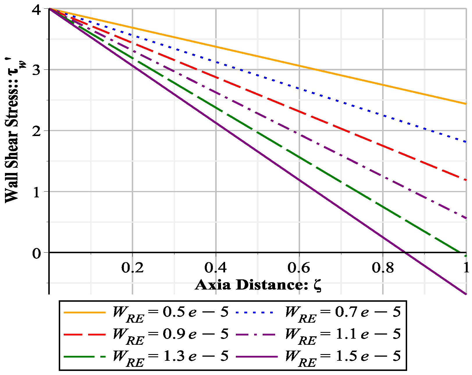
8.3. Wall Shear Stress

As wall shear stress is defined as:
τ w = μ u z r | r = R ,
or in terms of dimensionless variables given in (118)–(120) and making use of Equation (122) this can be expressed as:
τ w = | U z γ | γ = 1 .
τ w = 1 4 W R E δ N R E ζ 4 1 3 W R E 12 5 λ 1 W R E 2 2 3 λ 2 W R E 2 26 135 W R E 2 .

8.4. Fractional Rabsorption

As fractional reabsorption in a tube of length L is defined as:
F R = Q ( 0 ) Q ( L ) Q ( 0 ) ,
or in terms of dimensionless variables given in (118)–(120) the following simple linear relationship between F R and wall Reynolds number W R E is obtained:
F R = 4 W R E δ N R E .

8.5. Leakage Flux

As leakage flux is defined as:
q = Q ( z ) z , q = Q ( ζ ) ζ , q = 4 W R E δ N R E ,
where q = L q / Q * is dimensionless leakage flux.

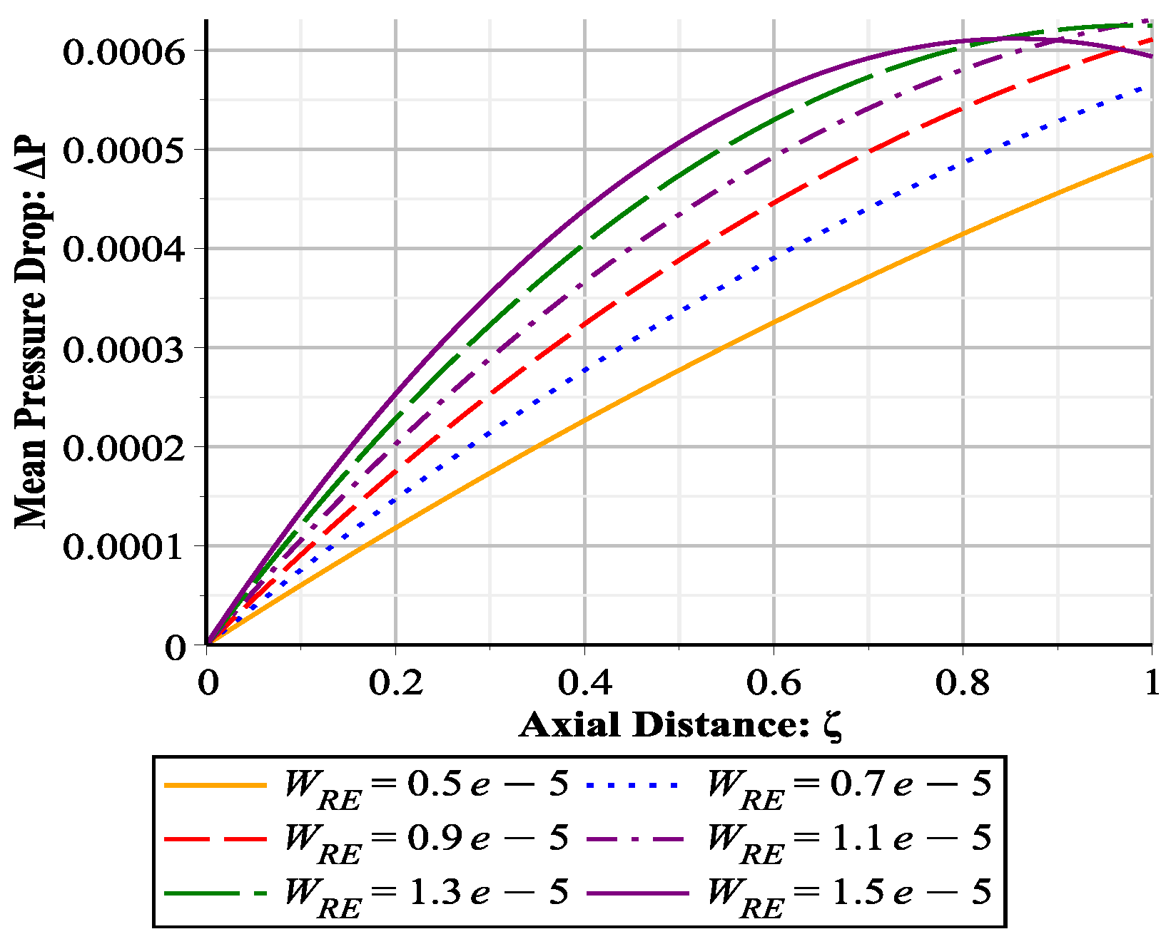
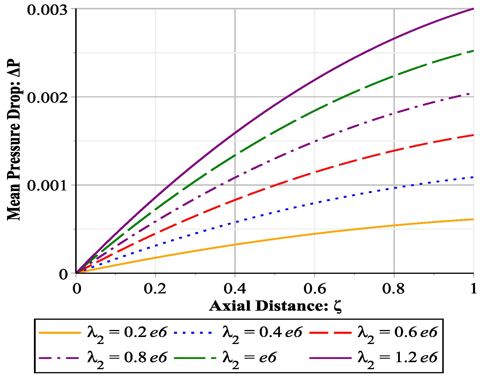
8.6. Mean Pressure Drop

The expression for hydrostatic pressure p can be readily obtained from (21) by plugging in the obtained third order expression for characteristic pressure p ^ given in Appendix A. Mean pressure at any z is defined as:
p z ¯ = 1 A A p ( r , z ) d A ,
where A is the area of cross section of the tube. Mean pressure drop Δ P = p 0 ¯ p z ¯ is computed and expressed in terms of dimensionless parameters as:
Δ P = 9752 4725 ζ ( 4725 2438 + ( λ 1 3 + 3293 1219 λ 2 + 407 9752 λ 1 2 + ( 26603 21064320 + 164725 1053216 λ 2 + 29805 19504 λ 2 2 ) λ 1 + 1135 22896 λ 2 2 + 2445 9752 λ 2 3 + 28243 14042880 λ 2 297221 5560980480 ) W RE 5 + 685 2438 λ 1 2 + 33 39008 + 35 53 λ 2 λ 1 + 240 1219 λ 2 2 3271 8425728 + 2835 156032 λ 2 W RE 4 605 117024 + 35 368 λ 1 W RE 3 2205 1219 λ 1 + 385 4876 W RE 2 + 14175 9752 + 4725 1219 λ 2 W RE ) N RE δ 2 W RE ζ .
Note that the mean pressure drop in major flow direction depends much upon W R E and non-Newtonian elastic and cross-viscosity parameters. The behavior of Δ P will be further investigated using graphical approach.

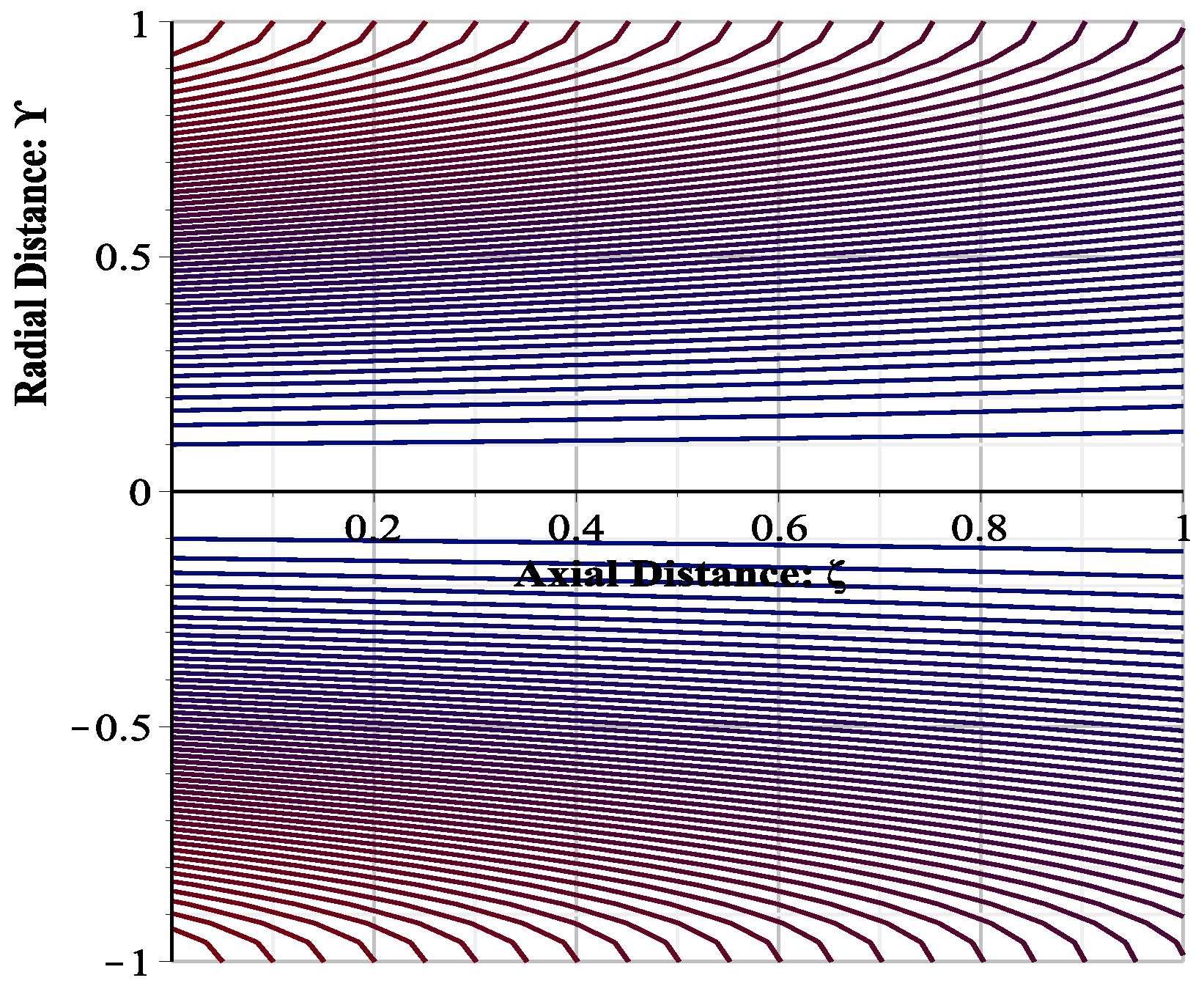
8.7. Stream Function

Using transformation (118)–(120) in Equation (89) the following dimensionless expression for stream function correct to third order is obtained:
Ψ ( γ , ζ ) = Q ( ζ ) 2 { 2 γ 2 γ 4 + W R E 36 4 γ 2 9 γ 4 + 6 γ 6 γ 8 + λ 1 W R E 2 45 36 γ 2 83 γ 4 + 60 γ 6 15 γ 8 + 2 γ 10 + λ 2 W R E 2 36 11 γ 2 28 γ 4 + 24 γ 6 8 γ 8 + γ 10 + W R E 2 5400 166 γ 2 380 γ 4 + 275 γ 6 75 γ 8 + 15 γ 10 γ 12 .

9. Graphical Results and Discussion

In order to understand the flow behavior and its dependence on parameters like porosity parameter W R E and non-Newtonian parameters λ 1 and λ 2 here the graphical representation is given to the expressions obtained in Section 8. Arbitrary values of some basic parameters are assumed in Table 1. Using these values it is found that δ = 1.6 × 10 3 and N R E = 3.2 × 10 2 . Inequality (126) can now be used to set a range of values for wall Reynolds number W R E so that to avoid any reverse flow. One can easily find that W R E 1.28 × 10 5 . On the basis of this analysis set W R E [ 0.5 , 1.5 ] × 10 5 for graphical representation. The values of elastic parameter α 1 and cross-viscosity α 2 are assumed to be of the order 10 1 , therefore values of dimensionless elastic parameter λ 1 and cross-viscosity parameter λ 2 are taken in the range [ 0.2 , 1.2 ] × 10 6 .
The non-dimensionalization of the variables reduces the number of parameters and makes the graphical representation of the physical quantities more convenient. The axial velocity profile W for different values of wall Reynolds number at three cross sections, ζ = 0.1 (beginning), ζ = 0.5 (middle) and ζ = 0.9 (end) of the tube is shown in the Figure 1, Figure 2 and Figure 3 respectively. It may be noted that the values of wall permeability parameter W R E have significant effect on the magnitude of the axial velocity in the middle and the end of the tube, however it has negligible influence in the beginning of the tube. It is found that the magnitude of axial velocity component decreases if the magnitude of the suction W R E increases. The reverse flow effect is observed when W R E assumes the threshold value W R E = 1.28 × 10 5 , see Figure 3. Furthermore the variation in non-Newtonian parameters λ 1 and λ 2 does not show any significant change in the axial velocity profile.
It is interesting to note that the expression (125) of the dimensionless volume flow rate Q is independent of the elastic parameter λ 1 and cross-viscosity parameter λ 2 . It can be noted that this expression matches exactly with the special cases present in References [1,16]. Behavior of the volume flow rate with wall Reynolds number given in the Figure 4 which shows that volume flow rate decreases with increase of W R E . Wall shear stress τ also decreases in the major flow direction and the role of W R E is to diminish it further, see Figure 5.
The relationship between mean pressure drop in longitudinal direction and W R E is given in Figure 6. Pressure drop increases with the increase value of wall Reynolds number. It can also be observed the elastic parameter λ 1 does not bring significant variation in pressure drop, however small changes in cross-viscosity parameter λ 2 bring significant changes in mean pressure drop (Figure 7).
In the Figure 8, Figure 9, Figure 10 and Figure 11 stream-lines are depicted for different values of W R E . Far away from the inlet of the tube there can be a point where flow rate becomes zero—stagnation point, beyond which the pressure starts to increase downstream and the fluid moves in z direction. This phenomena is called reverse flow, which can be seen clearly in Figure 11. The relationship between wall permeability parameter W R E and F R is shown in Table 2.
Expression of radial velocity (121) is independent of ζ and it attains maximum somewhere within the tube as shown in Figure 12. Using Newton Raphson method it is found that U r ( γ ) is maximum at γ 0.8164914227 and this critical point is independent of the wall Reynolds number W R E . However in Figure 12 the radial velocity profile can be seen to have a direct relationship with wall Reynolds number.

10. Conclusions

The foremost objective of this article was to investigate the effects of wall porosity parameter W R E and non-Newtonian parameters λ 1 and λ 2 on the variables of slow flow of a second order Rivlin-Ericksen fluid in a small diameter permeable tube. Although earlier work done by Macey [1] and Narasimhan [16] might be suitable for such flow problems, current study presents a more general analysis and results obtained by Macey and Narasimhan can be considered as special cases of solutions obtained here. Moreover our solution can be used in mathematical modeling of hollow fiber dialyzer when coupled with convection diffusion equation, in bio-sciences as well as in industry.
Emphasizing on the effects of wall porosity parameter W R E , elastic parameter λ 1 and cross-viscosity parameter λ 2 following conclusions are drawn:
  • If the elastic parameter λ 1 = 0 , the results obtained by Narasimhan [16] are achieved.
  • If λ 1 = λ 2 = 0 , the results obtained by Macey [1] are achieved.
  • Elastic parameter λ 1 does not bring any significant change in any of the flow variables in case of slow flow with small amount of cross flow.
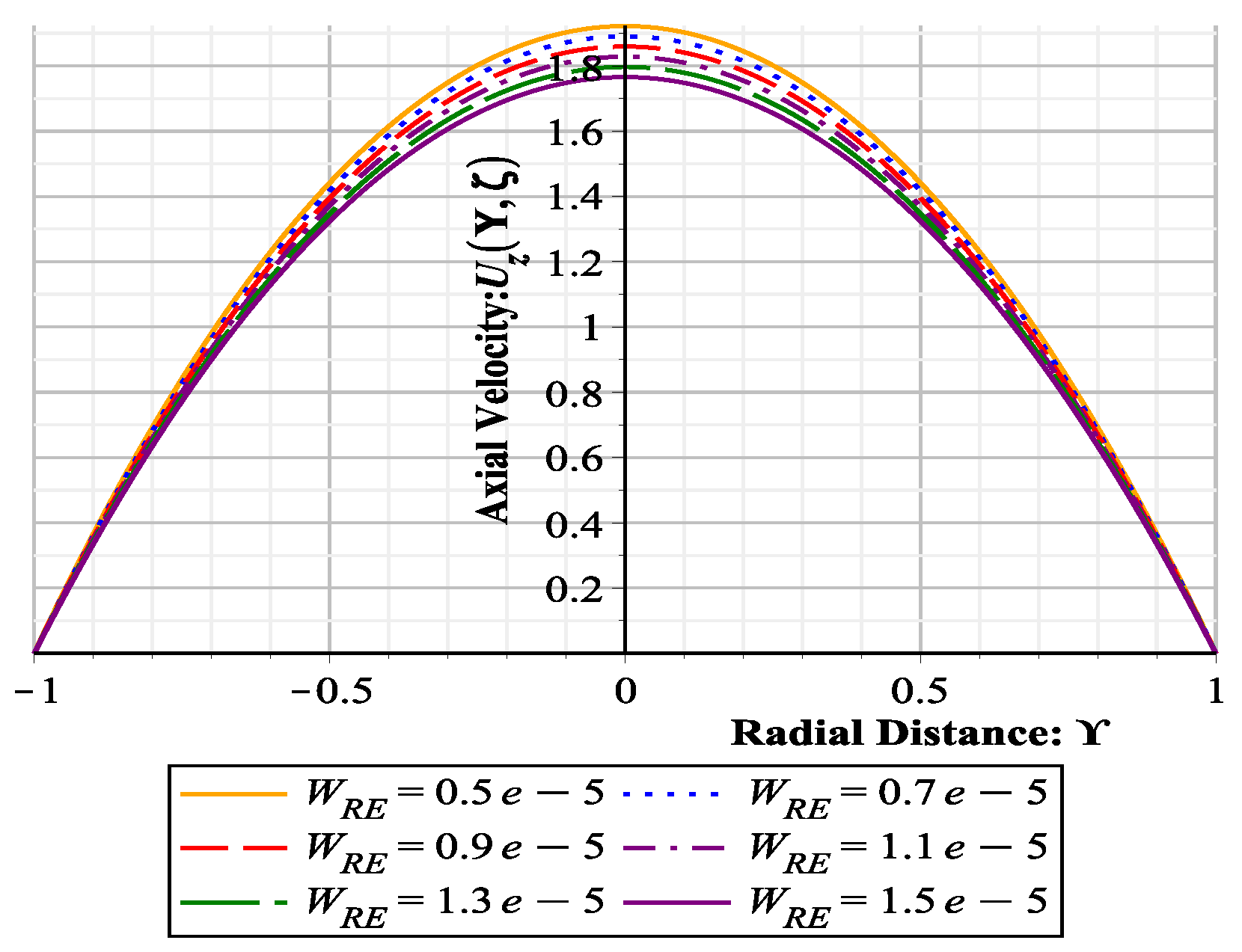
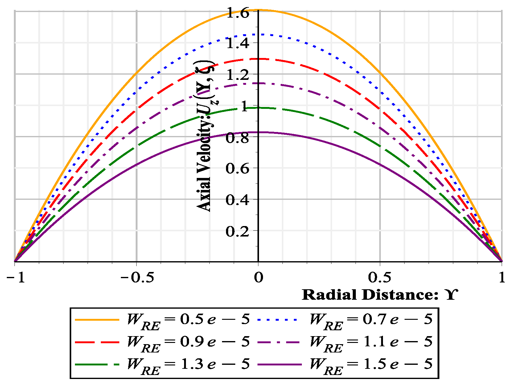
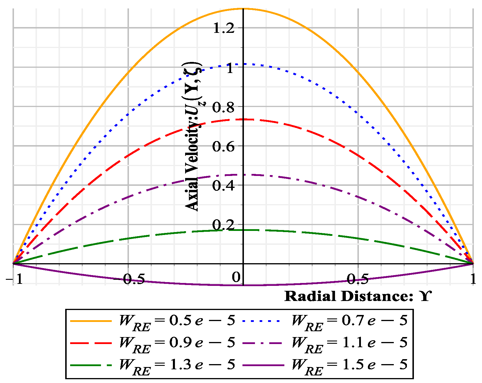
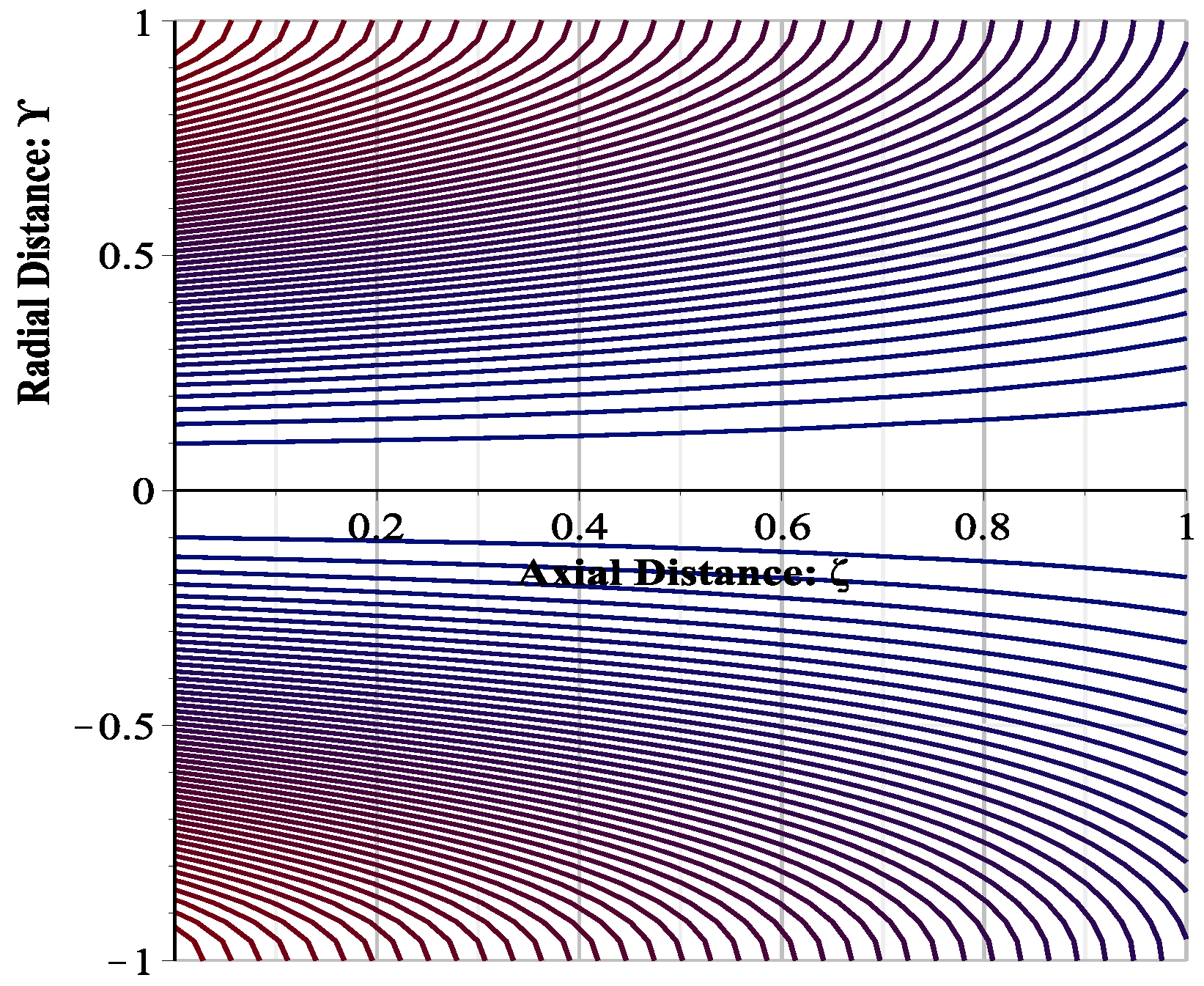
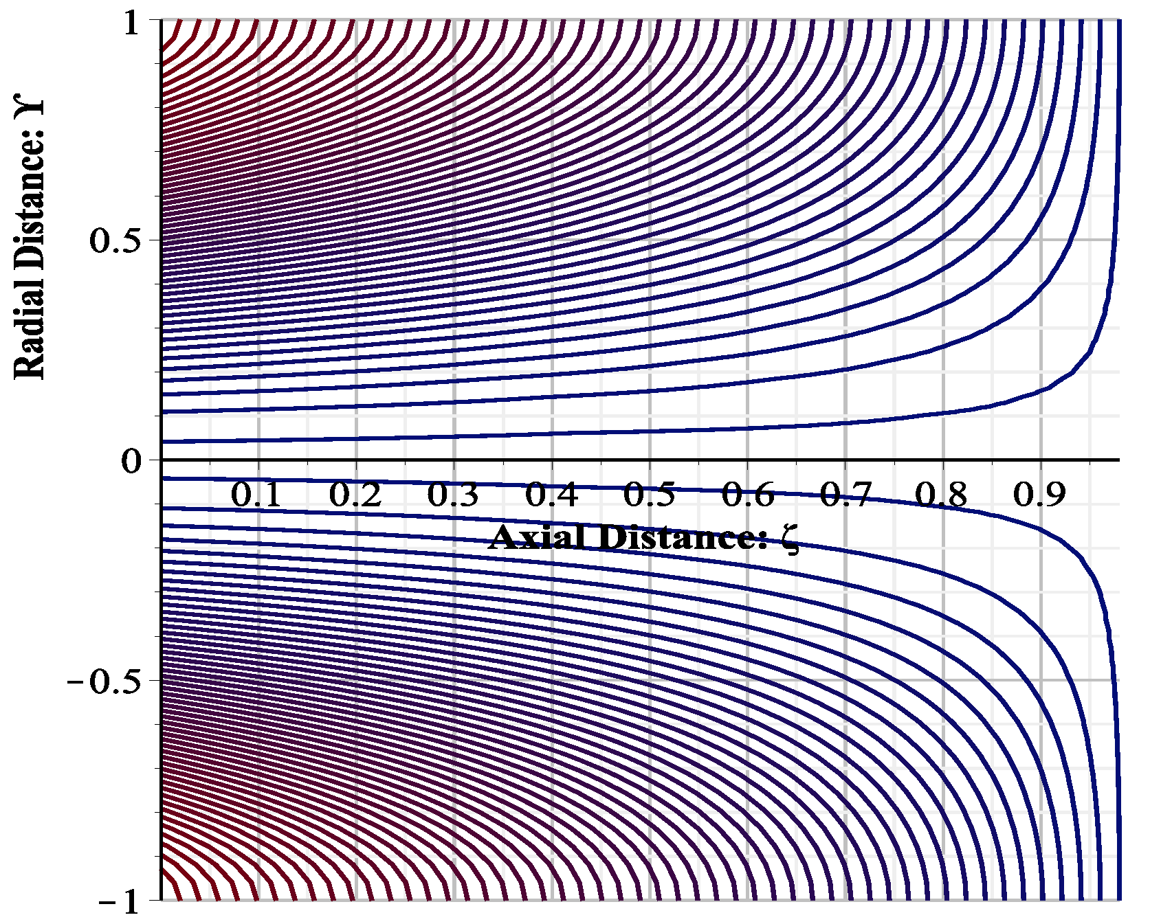
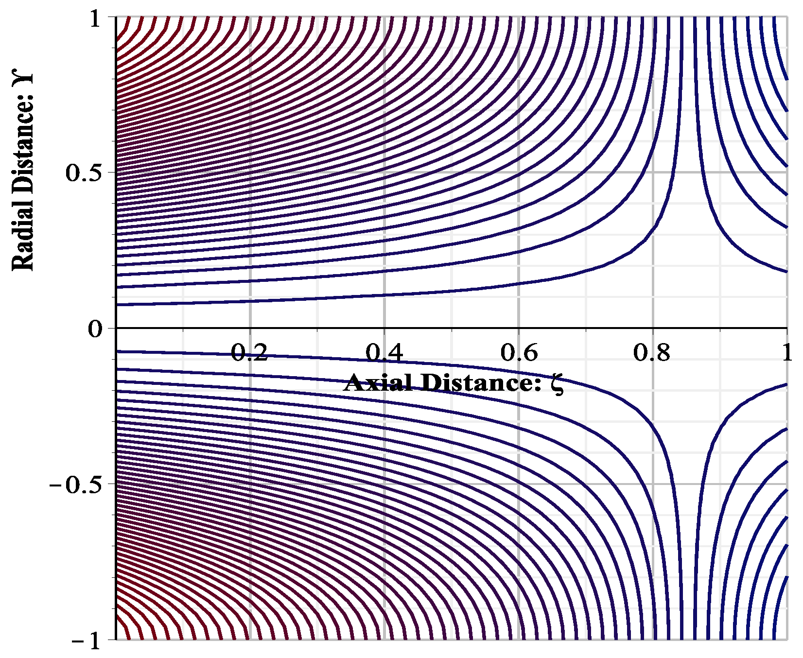
  • The magnitude of axial velocity component U z decreases if the magnitude of suction W R E increases. Reverse flow is observed when wall porosity parameter assumes value threshold value of W R E = 1.28 × 10 5 .
  • Volume flow rate is found to be independent of both the elastic parameter λ 1 and the cross-viscosity parameter λ 2 .
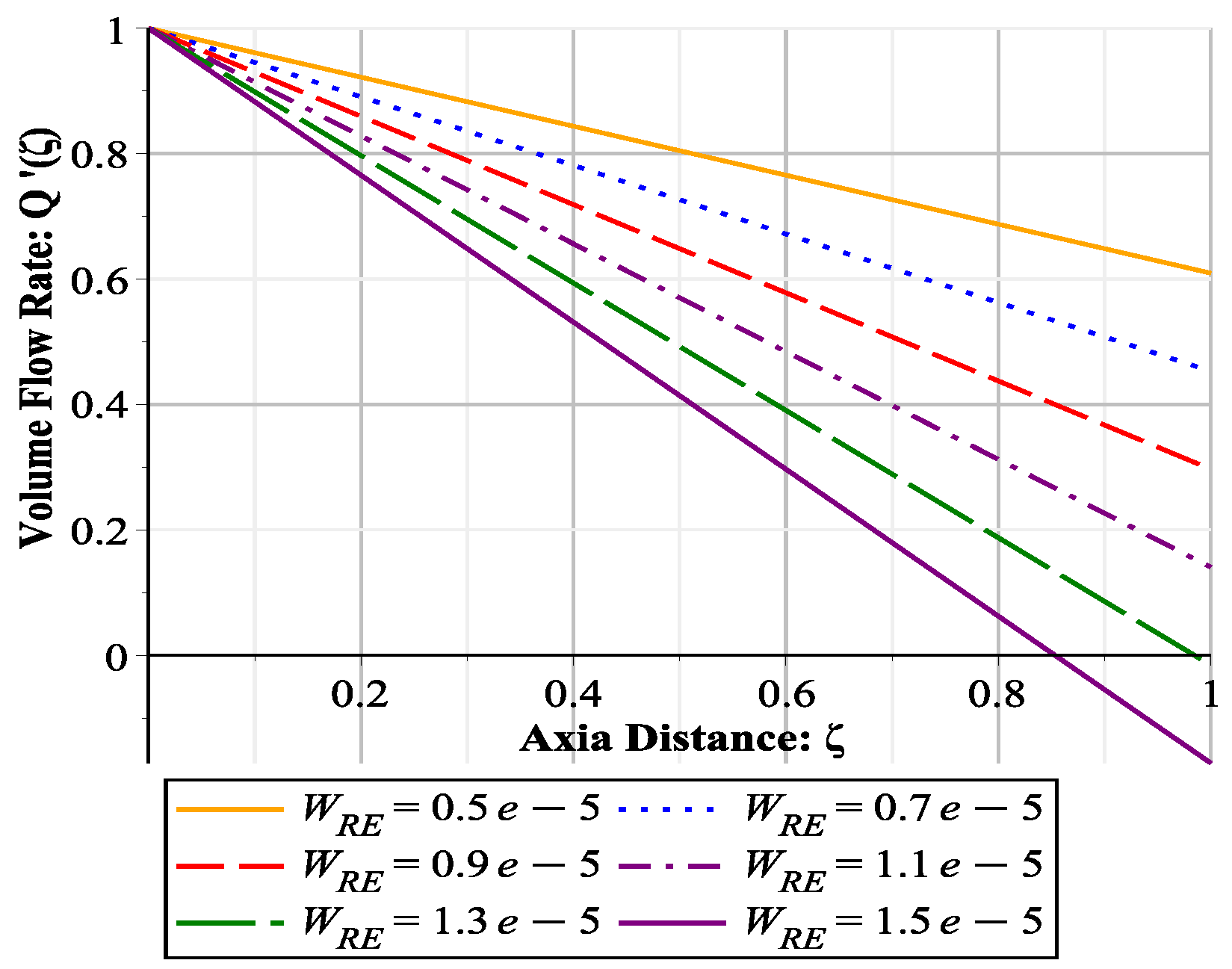
  • Volume flow rate and wall shear stress decrease in major flow direction if W R E increases.
  • Mean pressure drop in major flow direction increases with the increase of the value of wall Reynolds number W R E . It is also observed that elastic parameter λ 1 does not bring significant change in pressure drop, however pressure drop increases with increase of cross-viscosity parameter λ 2 .
  • Fractional reabsorption (FR) also increases with increase of W R E , this relationship is given in Table 2.
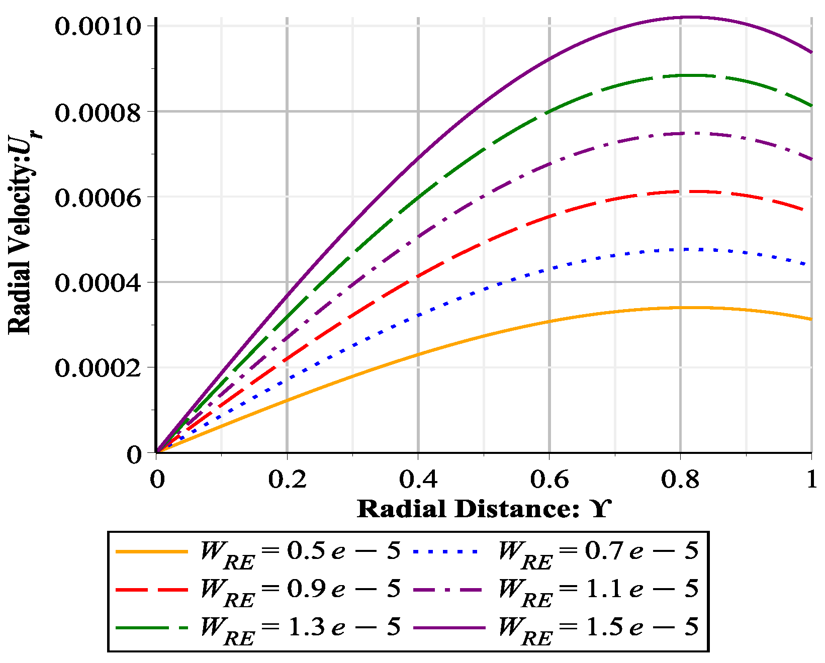
  • The radial velocity component U r is independent of ζ and attains maximum at γ = 0.81649144227 . The magnitude of radial velocity component increases with increase of W R E .

Author Contributions

Conceptualization, A.M.S. and Z.B.; methodology, K.B.; software, K.B.; validation, K.B., Z.B. and A.M.S.; formal analysis, K.B.; investigation, K.B.; resources, Z.B. and A.M.S.; data curation, K.B.; writing—original draft preparation, K.B.; writing—review and editing, K.B. and A.M.S.; visualization, Z.B.; supervision, Z.B. and A.M.S.; project administration, A.M.; funding acquisition, K.B. and Z.B. All authors have read and agreed to the published version of the manuscript.

Funding

This research received no external funding.

Acknowledgments

The authors are thankful to Sukkur IBA University for providing excellent research facilities.

Conflicts of Interest

The authors declare no conflict of interest.

Abbreviations

The following abbreviations and/or symbols are used in this manuscript:
α 1 Elastic parameter
α 2 Cross-viscosity parameter
δ Ratio of radius to length
γ Dimensionless coordinate of tube’s transversal axis, r R
λ 1 Dimensionless elastic parameter
λ 2 Dimensionless cross viscosity parameter
Ψ Dimensionless stream function
ψ Stream function
τ w Wall shear stress
τ w Dimensionless wall shear stress
θ Coordinate of tube’s azimuthal axis
ζ Dimensionless coordinate of tube’s longitudinal axis, z L
Δ P Mean pressure drop in major flow direction in the tube at point ζ
p ^ Characteristic pressure in the tube at point ( r , z )
F R Fractional reabsorption
LLength of the tube
N R E Inlet flow Reynolds number
PDimensionless pressure in the tube at point ( ζ , γ )
pPressure in the tube at point ( r , z )
QVolume flow rate at any point z
Q Dimensionless volume flow rate at any point ζ
Q * Inlet volume flow rate
qleakage flux
q Dimensionless leakage flux
RRadius of the tube
rCoordinate of tube’s transversal axis
U r Dimensionless fluid velocity along r-direction
U z Dimensionless fluid velocity along z-direction
u z Fluid velocity along z-direction
U * Cross flow radial velocity at wall of the pipe
W R E Wall Reynolds number
zCoordinate of tube’s longitudinal axis

Appendix A. Expression of Characteristic Pressure Correct to Third Order

The obtained expression of the characteristic pressure correct to third order is given below:
p ^ = 4 μ U * R r R 2 + 16 μ R 4 U * R z 2 2 Q * 2 π z + 4 U * R 3 U * R z 2 2 Q * 2 π z ρ 1 8 r R 2 + 4 r R 4 16 R 2 α 1 + α 2 1 r R 2 + U * 2 ρ r R 2 + r R 4 2 9 r R 6 + 4 R 2 α 1 + α 2 4 r R 2 r R 4 + 2 Q * 2 π 2 R 4 ρ 2 r R 2 + r R 4 + 4 R 2 α 1 + α 2 r R 2 + ρ U * 2 μ R 2 U * R z 2 2 Q * 2 π z { ρ 152 135 88 9 r R 2 + 16 r R 4 88 9 r R 6 + 16 9 r R 8 + α 1 R 2 448 45 96 r R 2 + 96 r R 4 320 9 r R 6 α 2 R 2 64 9 32 r R 2 + 32 r R 4 64 9 r R 6 } ρ U * 3 R μ { ρ 38 135 r R 2 + 11 36 r R 4 1 9 r R 6 + 1 36 r R 8 1 450 r R 10 + α 1 R 2 112 45 r R 2 + 2 r R 4 + 1 18 r R 8 α 2 R 2 16 9 r R 2 + 2 r R 4 8 9 r R 6 + 1 9 r R 8 } ρ U * Q * 2 π 2 μ R 3 { ρ 11 9 r R 2 + 2 9 r R 4 11 9 r R 6 + 2 9 r R 8 + α 1 R 2 12 r R 2 + 12 r R 4 40 9 r R 6 α 2 R 2 4 r R 2 + 4 r R 4 8 9 r R 6 } + K + o ( ϵ 3 ) ,

References

  1. Macey, R.I. Pressure flow patterns in a cylinder with reabsorbing walls. Bull. Math. Biophys. 1963, 25, 1–9. [Google Scholar] [CrossRef]
  2. Kelman, R.B. A theoretical note on exponential flow in the proximal part of the mammalian nephron. Bull. Math. Biophys. 1962, 24, 303–317. [Google Scholar] [CrossRef] [PubMed]
  3. Macey, R.I. Hydrodynamics in the renal tubule. Bull. Math. Biophys. 1965, 27, 117–124. [Google Scholar] [CrossRef] [PubMed]
  4. Palatt, P.J.; Sackin, H.; Tanner, R.I. A hydrodynamic model of a permeable tubule. J. Theor. Biol. 1974, 44, 287–303. [Google Scholar] [CrossRef]
  5. Pozrikidis, C. Stokes flow through permeable tubule. Arch. Appl. Mech. 2010, 80, 323–333. [Google Scholar] [CrossRef]
  6. Naqvi, S.; Haroon, T.; Siddiqui, A.M.; Sohail, A. Analysis of Stokes flow through periodic permeable tubules. Alex. Eng. J. 2017, 56, 105–113. [Google Scholar]
  7. Shreenivas, K.R.; Achala, L.N. Two dimensional flow in renal tubules with linear model. Adv. Appl. Math. Biosci. 2011, 2, 47–59. [Google Scholar]
  8. Siddiqui, A.M.; Haroon, T.; Shahzad, A. Hydrodynamics of viscous fluid through porous slit with linear absorption. Appl. Math. Mech.-Eng. Ed. 2016, 37, 361–378. [Google Scholar] [CrossRef]
  9. Kashan, M.; Iqbal, Z.; Siddiqui, A.M. Slip effects on the flow of Newtonian fluid in renal tubule. J. Comput. Theor. Nanosci. 2015, 12, 4319. [Google Scholar]
  10. Beavers, G.S.; Joseph, D.D. Boundary conditions at a naturally permeable wall. J. Fluid Mech. 1967, 30, 197–207. [Google Scholar] [CrossRef]
  11. Kashan, M.; Lu, D.; Gorji, M.R. Hydrodynamical study of flow in a permeable channel: Application to flat plate dialyzer. Int. J. Hydrog. Energy 2019, 44, 17041–17047. [Google Scholar] [CrossRef]
  12. Berman, A.S. Laminar flow in channels with porous walls. J. Appl. Phys. 1953, 24, 1232–1235. [Google Scholar] [CrossRef]
  13. Yuan, S.W. Further investigation of laminar flow in channels with porous walls. J. Appl. Phys. 1956, 27, 267–269. [Google Scholar] [CrossRef]
  14. Sellars, J.R. Laminar flow in channels with porous walls at high suction Reynolds numbers. J. Appl. Phys. 1955, 26, 489–490. [Google Scholar] [CrossRef] [Green Version]
  15. Donoughe, P.L. Analysis of Laminar Incompressible Flow in Semiporous Channels. NACA-TN-3759; 1956. Available online: https://ntrs.nasa.gov/search.jsp?R=19930084695 (accessed on 16 July 2020).
  16. Narasimhan, M.N.L. Laminar non-Newtonian flow in a porous pipe. Appl. Sci. Res. 1961, 10, 393–409. [Google Scholar] [CrossRef]
  17. Annan, K. Mathematical modeling for hollow fiber dialyzer: Blood and HCO3-dialysate flow characterstics. Int. J. Pure Appl. Math. 2012, 79, 425–452. [Google Scholar]
  18. Oxarango, L.; Schmitz, P.; Quintard, M. Laminar flow in channels with wall suction or injection: A new model to study multi-channel filtration systems. Chem. Eng. Sci. 2004, 59, 1039–1051. [Google Scholar] [CrossRef]
  19. Yu, J.; Chitalia, V.C.; Akintewe, O.O.; Edwards, A.; Wong, J.Y. Determinants of hemodialysis performance: Modeling fluid and solute transport in hollow-fiber dialyzers. Regen. Eng. Transl. Med. 2019. [Google Scholar] [CrossRef]
  20. Moussy, Y.; Snider, A.D. Laminar flow over pipes with injection and suction through the porous wall at Reynolds number. J. Membr. Sci. 2009, 327, 104–107. [Google Scholar] [CrossRef]
  21. Ullah, H.; Sun, H.; Siddiqui, A.M.; Haroon, T. Creeping flow analysis of slightly non-Newtonian fluid in a uniformly porous slit. J. Appl. Anal. Comput. 2019, 9, 140–158. [Google Scholar] [CrossRef]
  22. Ullah, H.; Siddiqui, A.M.; Sun, H.; Haroon, T. Slip effects on creeping flow of slightly non-Newtonian fluid in a uniformly porous slit. J. Braz. Soc. Mech. Sci. Eng. 2019, 41, 412. [Google Scholar] [CrossRef]
  23. Kacou, A.; Rajagopal, K.R.; Szeri, A.Z. A thermodynamical analysis of journal bearings lubricated by a non-Newtonian fluid. J. Tribol. 1988, 110, 414–420. [Google Scholar] [CrossRef]
  24. Ng, C.W. Saibel, Nonlinear viscosity effects in slider bearing lubrication. ASME J. Fluid. Eng. 1974, 56, 191–252. [Google Scholar]
  25. Rivlin, R.S.; Ericksen, J.L. Stress-deformation relations for isotropic materials. J. Ration. Mech. Anal. 1955, 4, 523–532. [Google Scholar] [CrossRef]
  26. Sinha, A. MHD flow and heat transfer of a third order fluid in a porous channel with stretching wall: Application to hemodynamics. Alex. Eng. J. 2015, 54, 1243–1252. [Google Scholar] [CrossRef] [Green Version]
  27. Leal, L.G. The slow motion of slender rod-like particles in a second-order fluid. J. Fluid Mech. 1975, 69, 305–337. [Google Scholar] [CrossRef] [Green Version]
  28. Imran, A.; Rana, M.A.; Siddiqui, A.M.; Shoaib, M. Flow of second grade fluid in a scraped surface heat exchanger. J. Food Process Eng. 2017, 40, e12393. [Google Scholar] [CrossRef]
  29. Tai, C.W.; Wang, S.; Narasimhan, V. Cross-stream migration of non-spherical particles in a second-order fluid—Theories of particle dynamics in arbitrary quadratic flows. J. Fluid Mech. 20202, 895. [Google Scholar] [CrossRef]
  30. Siddiqui, A.M.; Haroon, T.; Bano, Z. Steady 2-D flow of a second grade fluid in a symmetrical diverging channel of varying width. Appl. Math. Sci. 2014, 8, 4675–4691. [Google Scholar] [CrossRef]
  31. Langlois, W.E. A recursive approach to the theory of slow, steady-state viscoelastic flow. Trans. Soc. Rheol. 1963, 7, 75–99. [Google Scholar] [CrossRef]
  32. Langlois, W.E. The recursive theory of slow viscoelastic flow applied to three basic problems of hydrodynamics. Trans. Soc. Rheol. 1964, 8, 33–60. [Google Scholar] [CrossRef]
  33. Fosdick, R.L.; Dunn, J.E. Thermodynamics, stability and boundedness of fluids of complexity 2 and fluids of second grade. Arch. Ration. Mech. Anal. 1974, 56, 191–252. [Google Scholar]
Figure 1. Behavior of U z ( γ , ζ ) with γ at ζ = 0.1 for different values of W R E .
Mathematics 08 01170 g001
Figure 2. Behavior of U z ( γ , ζ ) with γ at ζ = 0.5 for different values of W R E .
Mathematics 08 01170 g002
Figure 3. Behavior of U z ( γ , ζ ) with γ at ζ = 0.9 for different values of W R E .
Mathematics 08 01170 g003
Figure 4. Behavior of Q’ ( ζ ) with ζ for different values of W R E .
Mathematics 08 01170 g004
Figure 5. Behavior of τ w ’ with ζ for different values of W R E .
Mathematics 08 01170 g005
Figure 6. Behavior of Δ P with ζ for different values of W R E .
Mathematics 08 01170 g006
Figure 7. Behavior of Δ P with ζ for different values of λ 2 .
Mathematics 08 01170 g007
Figure 8. Stream lines for W R E = 0.5 × 10 5 .
Mathematics 08 01170 g008
Figure 9. Stream lines for W R E = 0.9 × 10 5 .
Mathematics 08 01170 g009
Figure 10. Stream lines for W R E = 1.3 × 10 5 .
Mathematics 08 01170 g010
Figure 11. Stream lines for W R E = 1.5 × 10 5 .
Mathematics 08 01170 g011
Figure 12. Behavior of U r ( γ ) with γ for different values of W R E .
Mathematics 08 01170 g012
Table 1. Assumed values of dimensions of the tube and some basic flow parameters.
QuantitySymbolValue
Length of the TubeL 0.67 cm
Radius of the TubeR 1.08 × 10 3 cm
Inlet Volume Flow Rate Q * 4.02 7 cm 3 /s
Dynamic Viscosity μ 7.37 × 10 3 dyn·s/cm 2
Table 2. Variation in fractional reabsorption F R with wall Reynolds number W R E for N R E = 3.2 × 10 2 .
W RE 0.5 × 10 5 0.7 × 10 5 0.9 × 10 5 1.1 × 10 5 1.3 × 10 5 1.5 × 10 5
FR 0.3906 0.5468 0.7032 0.8592 1.016 1.172

