Article

Analytical Predictions on the Ground Responses Induced by Shallow Tunneling Adjacent to a Pile Group

1
Key Laboratory of Urban Security and Disaster Engineering of Ministry of Education, Beijing University of Technology, Beijing 100124, China
2
Beijing Municipal Construction Group Co., Ltd., Beijing 100089, China
*
Author to whom correspondence should be addressed.
Mathematics 2023, 11(7), 1608; https://doi.org/10.3390/math11071608
Submission received: 15 February 2023 / Revised: 20 March 2023 / Accepted: 23 March 2023 / Published: 27 March 2023

Abstract

:
Prevalent buildings are supported by pile foundations in urban areas, and the importance of nearby excavation prediction is indisputable due to various engineering accidents caused by the density of urban buildings and the complexity of the underground environment. Recently, a case of tunneling adjacent to a pile group has received a lot of attention from the research community and engineers. In this study, a mechanical model of a shallow tunnel adjacent to a pile group is established. The proposed stress-release function is taken as the stress boundary condition of the tunnel periphery. Considering the pile group, the elastic stresses are calculated by complex variable theory, combined with the Mindlin’s solution. Then, the new analytical solutions to stress are obtained to predict the stratum responses induced by tunneling adjacent to the existing pile group loads inside the stratum in a gravity field. Ultimately, this study provides parameters to analyze their influence on ground stress and potential plastic zone, such as the stress release coefficient, pile group locations, and soil parameters. This research provides a theoretical basis for stratum stresses’ prediction in shallow tunneling engineering fields when tunneling adjacent to a pile group, and it can be applied to the construction of resilient cities.

1. Introduction

Owing to the continuous expansion of cities and decreases in available land, the demand for urban tunnels has sharply increased in recent years [1,2,3,4,5]. Unavoidably, tunnel construction is disturbed by the foundations of nearby existing structures, particularly in densely constructed areas located adjacent to tunnel construction sites. More and more buildings are supported by pile foundations. Under the coupling effect of pile foundation loadings and tunnel excavation, the soil around the tunnel and pile foundations may experience stress redistribution or yield prior to support installation, which can adversely affect and even destabilize the surrounding ground. To ensure the safety of tunneling operations and nearby existing structures, a new analytical solution is required, by means of which the ground responses around shallow tunnels adjacent to pre-existing pile group loads can be reasonably predicted.
Traditional methods, namely empirical methods, analytical methods, numerical methods and model test methods have made great accomplishments in the study of ground displacement and stress by tunneling. The empirical methods [6,7,8,9,10] are routinely used to investigate ground responses using the Peck theory, Celestino theory. Additionally, these methods are fitted intuitively from measured data and lack rigorous theory. With the development of computer technology, a more accurate prediction, considering complex excavation process and geological conditions such as the soil elastoplastic or elasto-viscoplastic property, can be obtained via numerical analysis [11,12,13]. Numerical simulation can consider various tunnel cross-section shapes, nonlinear effects of stratum mechanics, complex construction procedures, and the coupling interaction between surrounding rock and tunnel structures. It is a commonly used method for studying the response of strata and tunnel structures induced by tunneling. The model test methods [14] can more realistically reflect the ground deformation laws due to the reliability of soil parameters.
Compared with other three methods, the analytical methods based on a rigorous mathematical derivation can consider the quantitative effects of geomechanical and geometric parameters [15,16,17]. At present, there are four main theoretical analysis methods for predicting the ground stresses caused by tunneling, namely the Airy stress function method [18], the virtual image method [19,20], the bipolar coordinate method [21,22] and complex variable theory [23,24,25]. The stress function method can obtain the elastic solution of a deep circular tunnel, but it cannot obtain the analytical solution of a deep tunnel of other shapes, nor can it obtain the analytical solution of a shallow tunnel. The bipolar coordinate method can obtain the analytical solution of stress field, but cannot obtain the accurate displacement solution. The complex variable theory can solve the shortcomings of the above methods well, and has been widely used to solve the elastic solution of tunnel excavation in recent years.
Markedly, considering the existence of surface and gravity field, the problem of shallow tunnels is more complicated than that of deep tunnels, and the complex variable theory using the Laurent series and conformal mapping is appropriate for shallow tunnels. This method uses conformal mapping on the ring so that the depth of the tunnel only affects the thickness of the ring wall and does not affect the function analysis in the complex variable solution procedure. The characteristics of this solution are that the complex variable method can guarantee the continuity of the boundary in the theoretical analysis, and reasonable boundary conditions are a key factor to obtain the solution of shallow tunnels [26,27]. For instance, Lu et al. [28] provided the analytical solution of a shallow tunnel that had excavation stress on the tunnel periphery and was stress-free on the ground surface, considering the linear variations of the initial stresses with depth and lateral stress coefficients. Lu et al. [29] discussed the case of a shallow circular hydraulic tunnel filled with water in an elastic rock mass with gravity. Furthermore, Kong et al. [30] proposed a unified stress function as the stress boundary condition of a tunnel periphery to describe the vertical and horizontal stress distributions of an underwater shallow tunnel. Using complex variable theory and the integration of Flamant’s solutions, Wang et al. [31] obtained an elastic analytical solution with surcharge loadings on ground surface. Yang et al. [32] solved the problem of a shallow tunnel with a nearby cavern; they used a complex variable method and the Schwarz alternating method to study the interaction between the tunnel and the cavern. However, these provided analytical solutions cannot determine the ground stress field under the influence of an adjacent pile group.
With regard to the analytical study of a combination of tunnel and pile foundations, Marshall et al. [33] used a spherical cavity expansion analysis method to evaluate the end-bearing capacity of the pile and estimate the effect that constructing a new tunnel will have on an existing pile. Cao et al. [6] investigated the mechanical mechanism of the effects of the isolation piles on the ground vertical displacements using a modified Loganathan–Poulos formula and the Melan solution of the vertical displacement in a general form. Xiang et al. [34] mainly studied the potential plastic zone caused by tunneling in the vicinity of single pile foundation; however, the gravity field was not considered. Generally, these solutions cannot clearly estimate the stratum stress field induced by shallow tunneling adjacent to vertical pile group loads.
For abovementioned studies, nevertheless, existing studies have generally focused on the ground responses of tunneling in greenfield; with caverns and with surcharge loadings on the ground surface, the case of existing pile group loads in the interior of the stratum has not been highlighted. Accordingly, to fill a gap in the area of theoretical analytic solutions, this study paves the way for predicting ground stresses induced by tunneling in non-greenfield.
This study reports a combinatory strategy, including Mindlin’s solution and complex variable theory, to further improve the influence mechanism of shallow tunnel excavation under the influence of a pile group in a gravity field. In this paper, based on the plane strain condition and the elastic constitutive relation, the analytical solutions of stress induced by shallow tunneling adjacent to pile group loads are obtained using analytical methods; due to the limitations of the conformal mapping function, the current shallow buried semi-infinite domain mechanical model can only obtain analytical solutions for circular tunnels. Therefore, the proposed method may only be used to solve the analytical solutions of strata induced by circular tunnels. Notably, the proposed stress release function is introduced as the boundary condition into the complex variable solving process, which is detailed in Section 3.3.1. The remainder of the paper is organized as follows: Section 2 introduces the mechanical model and method framework of theoretical prediction; Section 3 presents the derivation process of new analytical solution and its feasibility; and Section 4 illustrates the application of the solution and analyzes the influence of the stress release coefficient, pile group parameters and soil parameters on the stratum stress field and potential plastic zone. Eventually, the authors believe that it will be useful to decide a reasonable location for tunnel construction in preliminary designs.

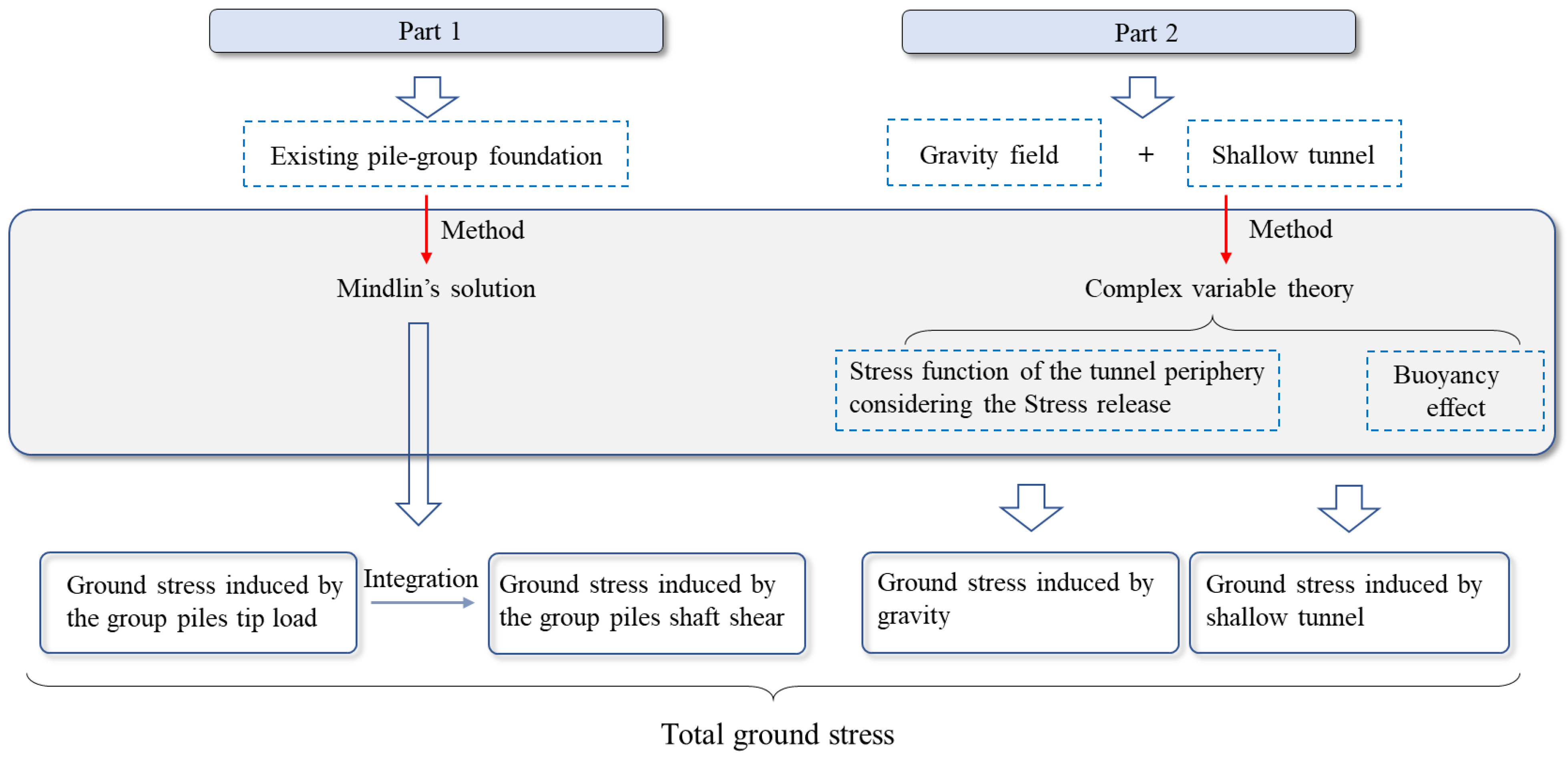
2. Mechanical Model and Method Framework

In urban tunnel engineering, it is common for shallow tunnels to pass through an adjacent superstructure. The smaller the depth of shallow tunnel, the more significant the impacts on adjacent buildings, such as building cracking, distortion, uneven settlement, and collapse [35,36,37,38]. This factor should be seriously emphasized. Furthermore, the loads of superstructures are transferred to the stratum through pile group foundations. If the loads are simplified as vertical loads in the ground, this case can be modelled as a tunnel being excavated after the application of vertical loads in the ground. Based on these assumptions, a mechanical model that demonstrates excavation of a shallow tunnel with existing pile group loads in the ground is proposed.

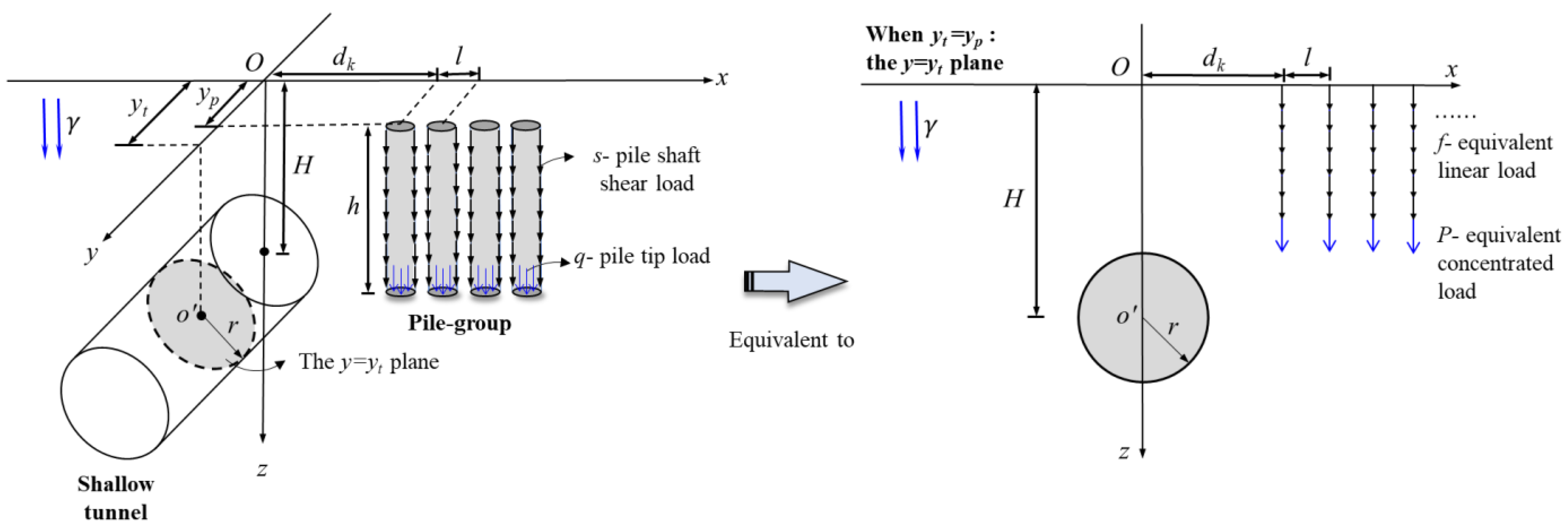
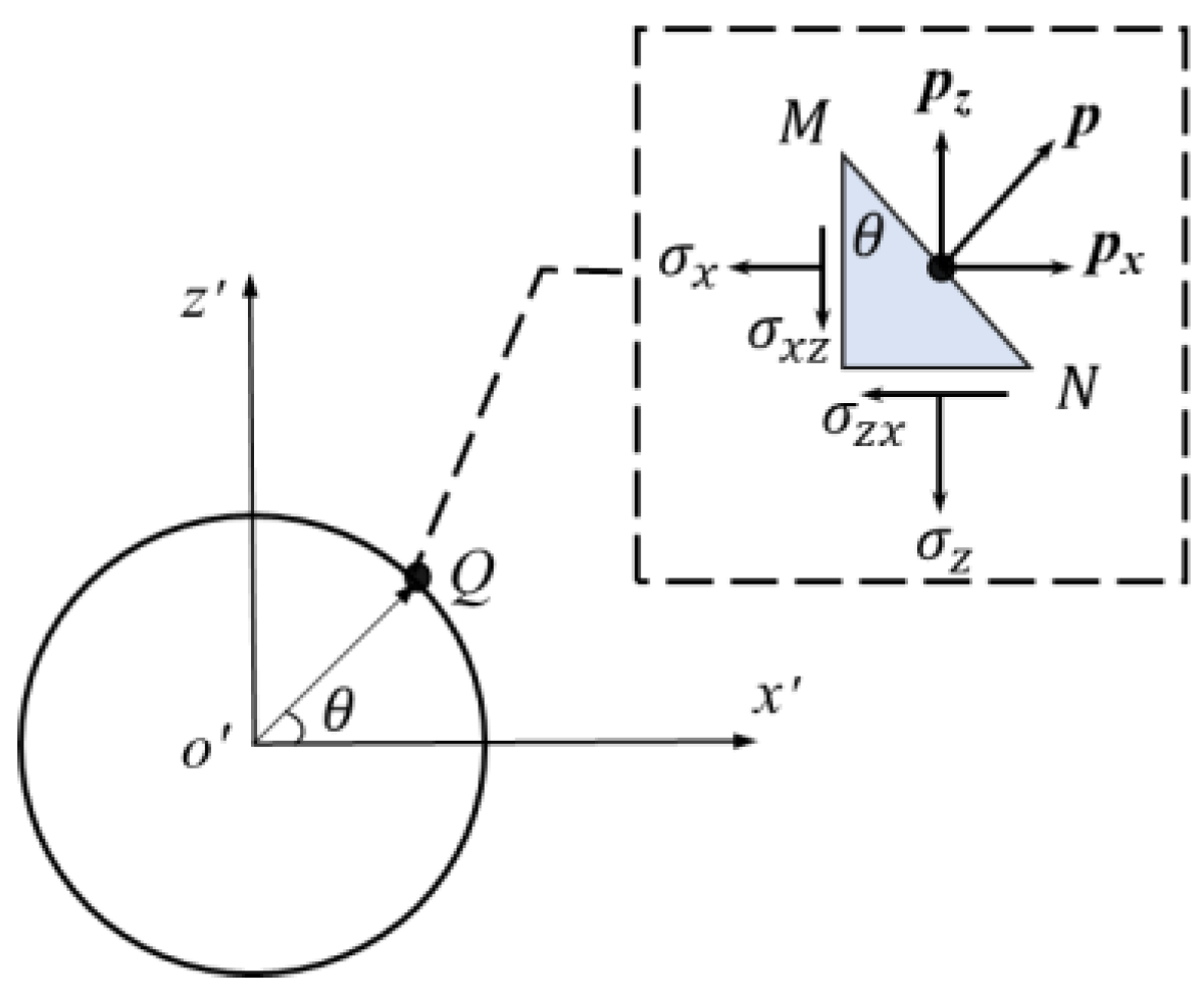
2.1. Establishment of Mechanical Model

Referring to the three-dimensional mechanical model shown in Figure 1, the plane y = yt vertical to the tunnel axis is considered. Notably, the pile group and shallow tunnel are in the same plane when yt = yp; the pile group is not in the same plane as the tunnel when yt yp, which is a three-dimensional problem.
In Figure 1, yt, yp are y coordinates of the tunnel section and pile group, respectively. The pile loads in the ground consist of two parts: the pile tip load q and the pile shaft shear load s. For the convenience of calculations, the pile loads are simplified to an equivalent concentrated load P and equivalent linear load f along the longitudinal axis. The horizontal coordinate of the first pile load dk is adopted to represent the location of the pile group, and l is the pile spacing.
As shown in Figure 1, this is a semi-infinite domain model which considers the surface boundary to realize the stratum stress analysis of shallow tunnel with existing pile group loads. The shallow tunnel is affected by the surface boundary and the gravity is the main external load, so the load change of gradient should be considered. Assuming that the ground is a homogeneous, isotropic and ideal elastic-plastic material, the changes in stratum stress caused by pile group loads and tunneling can be considered a linear elastic response.

2.2. Method Framework

According to the mechanical model in Figure 1, the final ground stress solution can be divided into two parts: (1) the stress induced by pile group loads, (2) the stress induced by tunneling in greenfield (where there are no existing foundations in the ground). The former uses the Mindlin’s solution [39] in the classical elastic theory, which gives the solution of the displacement and stress of the stratum caused by the vertical force acting on a point in the semi-infinite space. Complex variable theory is used as the latter’s method to predict tunneling-induced stress. The prediction process of the stress solution and potential plastic zone of ground are yielded as follows:
(I) The elastic theory Mindlin’s solution and its integral along the pile length, respectively, to equivalent concentrated load P and equivalent linear load f are used to calculate the ground stress solution.
(II) The analytical solution of the ground stress caused by shallow tunneling in the gravity field is obtained by complex variable theory using the stress boundary condition considering the stress release coefficient, and the ground stress is calculated by substituting the parameter values and coordinate values.
(III) The ground stress induced by tunneling and pile group loads is superimposed.
(IV) The Mohr–Coulomb criterion is substituted and the mathematical software Matlab is used to calculate the total ground stress and predict the shape and extent of the potential plastic zone.
The theoretical calculation steps are shown in Figure 2.

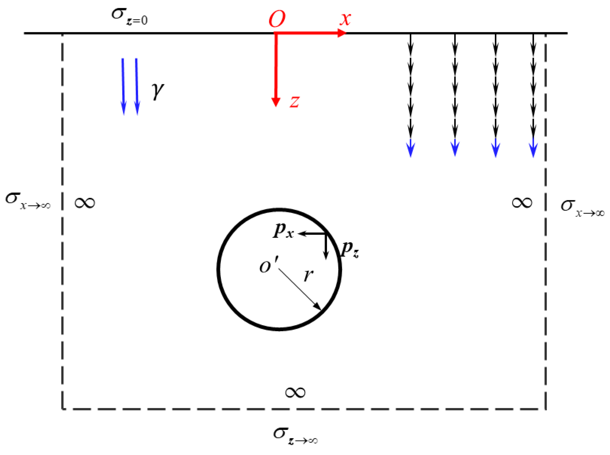
3. Analytical Solutions of Stress for Tunneling Adjacent to Pile Group

The elastic analytical stresses induced by a pile group for the vertical force acting at a point in the ground have been provided by Mindlin [39]. Thus, the solutions of stress for tunneling adjacent to a pile group proposed in this study use Mindlin’s solution and its integral combined with a complex variable method. In order to reflect the factual situation, the gravity is applied in the vertical direction, and the arbitrary stress in the horizontal direction before the excavation. Besides, the buoyancy effect and the stress release are considered in the tunnel periphery after the excavation.

3.1. Stress Boundary Conditions

The general boundary conditions corresponding to the mechanical model in Figure 1 are shown in Figure 3. The boundary equations are given in Equation (1):
{ σ z = 0 = 0 σ x = k 0 γ z + σ x 1 σ z = γ z + σ z 1 σ s = p x + i p z
where γ is uniform volumetric weight. k0 is the lateral stress coefficient and is equal to v/(1 − v). v is the Poisson’s ratio. σx1 and σz1 are the ground stresses induced by the pile group, σs is the stress boundary condition of the tunnel periphery, and px, pz are the stress boundary functions of tunnel paralleled to the x and z axes, respectively.
The general boundary conditions can be broken into three parts, as shown in Figure 4, i.e., Part 1, Part 2a and Part 2b. Part 1 indicates that only pile group loads are applied in the ground, and there is no excavation of the tunnel, i.e., the tunnel section is in the initial stress state (Section 3.2). Part 2 is broken down into two parts: Part 2a in the unexcavated state of the tunnel and Part 2b in the excavated state of the tunnel (Section 3.3).

3.2. Analytical Solution of Pile Group Loads

The ground stresses due to simplified pile group loads in the xz plane can be obtained using the Mindlin’s solution, which consists of two sections: the equivalent concentrated load P and the equivalent linear load f.

3.2.1. Ground Stress Induced by Pile Group Tip Loads

The pile group tip loads can be simplified to equivalent concentrated load P at the pile tip. Then, by the principle of Mindlin’s solution and summation, the stresses generated at any point (x, y, z) in the ground when multiple loads are applied in a three-dimensional semi-infinite elastomer are as follows:
σ x 1 p = k = 1 m P k 8 π ( 1 v ) f x ( x , z ; h ) = k = 1 m P k 8 π ( 1 v ) { ( 1 2 v ) ( z h ) R 1 3 3 ( x d k ) 2 ( z h ) R 1 5 + ( 1 2 v ) [ 3 ( z h ) 4 v ( z + h ) ] R 2 3 3 ( 3 4 v ) ( x d k ) 2 ( z h ) 6 h ( z + h ) [ ( 1 2 v ) z 2 v h ] R 2 5 30 h z ( x d k ) 2 ( z + h ) R 2 7 4 ( 1 v ) ( 1 2 v ) R 2 ( R 2 + z + h ) ( 1 ( x d k ) 2 R 2 ( R 2 + z + h ) ( x d k ) 2 R 2 2 }
σ z 1 p = k = 1 m P k 8 π ( 1 v ) f z ( x , z ; h ) = k = 1 m P k 8 π ( 1 v ) { ( 1 2 v ) ( z h ) R 1 3 3 ( z h ) 3 R 1 5 + ( 1 2 v ) ( z h ) R 2 3 3 ( 3 4 v ) z ( z + h ) 2 3 h ( z + h ) ( 5 z h ) R 2 5 30 h z ( z + h ) 3 R 2 7 }
σ x z 1 p = k = 1 m P k ( x d k ) 8 π ( 1 v ) f x z ( x , z ; h ) = k = 1 m P k ( x d k ) 8 π ( 1 v ) { 1 2 v R 1 3 3 ( z h ) 2 R 1 5 + 1 2 v R 2 3 3 ( 3 4 v ) z ( z + h ) 3 h ( 3 z + h ) R 2 5 30 h z ( z + h ) 2 R 2 7 }
where m represents the number of piles, σ x 1 p , σ z 1 p and σ x z 1 p denote the horizontal stress, vertical stress and shear stress in the y = yt plane, respectively, induced by equivalent concentrated load Pk at the pile tip.
R 1 = ( x d k ) 2 + ( y t y p ) 2 + ( z h ) 2 ,   R 2 = ( x d k ) 2 + ( y t y p ) 2 + ( z + h ) 2 ,   k = 1 , 2 , 3 , 4 ,

3.2.2. Ground Stress Induced by Pile Group Shaft Shear Loads

For the shaft shear loads simplified to equivalent linear load f along the longitudinal axis, the analytical solutions of the ground stress obtained by integrating Equations (5)–(7) are as follows:
σ x 1 f = k = 1 m 0 h f k 8 π ( 1 v ) f x ( x , z ; b ) d b
σ z 1 f = k = 1 m 0 h f k 8 π ( 1 v ) f z ( x , z ; b ) d b
σ x z 1 f = k = 1 m 0 h f k ( x d k ) 8 π ( 1 v ) f x z ( x , z ; b ) d b
where h is the pile length and b is the integration variable along the pile length, and σ x 1 f , σ z 1 f and σ x z 1 f denote the horizontal stress, vertical stress and shear stress in the y = yt plane, respectively, induced by equivalent linear load fk along the pile length.
R 1 = ( x d k ) 2 + ( y t y p ) 2 + ( z l ) 2 ,   R 2 = ( x d k ) 2 + ( y t y p ) 2 + ( z + l ) 2 ,   k = 1 , 2 , 3 , 4 ,

3.2.3. Stress Superposition

Considering the joint effect of the tip loads and the shaft shear loads of pile group, the stress solution of Part 1 can be obtained using Equation (8):
{ σ x 1 = σ x 1 p + σ x 1 f σ z 1 = σ z 1 p + σ z 1 f σ x z 1 = σ x z 1 p + σ x z 1 f

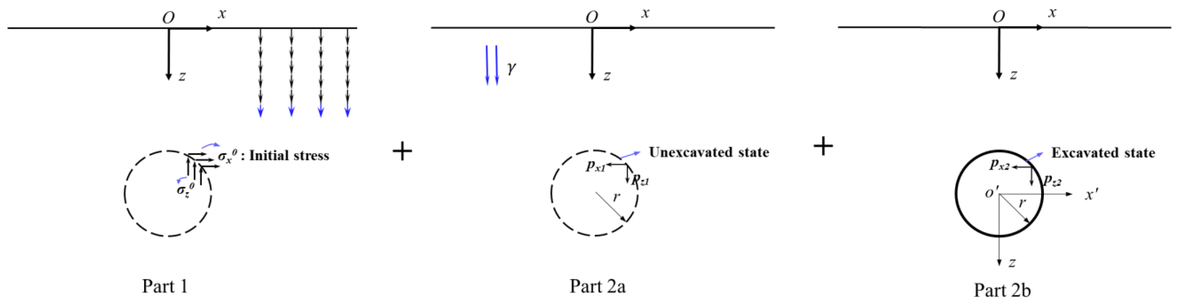
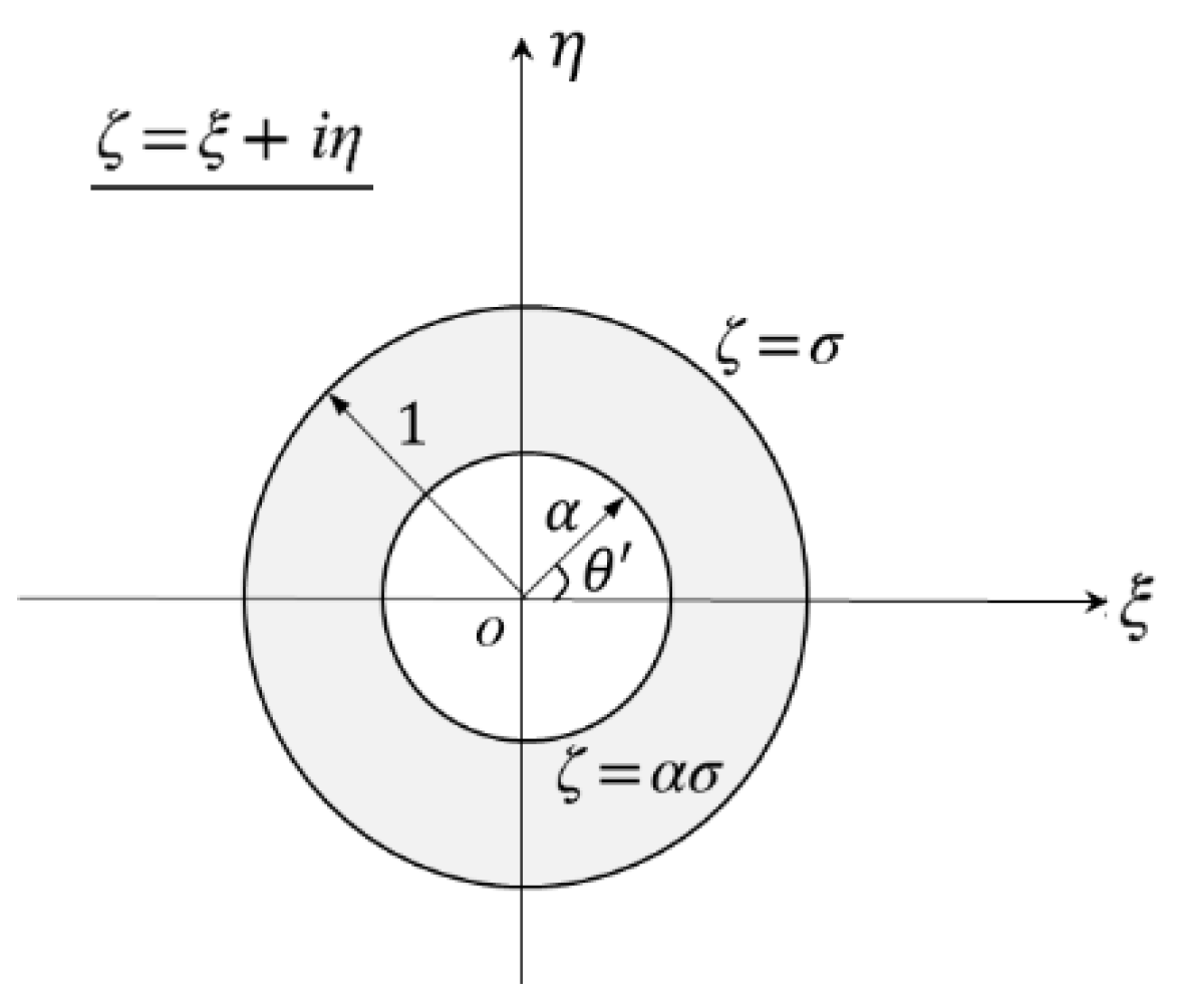
3.3. Analytical Solution of Shallow Tunnel in Greenfield

The shallow tunnel excavated in an elastic soil can be considered an elastic half-plane problem (Part 2). Firstly, under the influence of gravity field, the ground stress is as shown in Equation (12) before excavation (Part 2a). Then, using the complex variable theory for the shallow tunnel, the ground stress after excavation in free strata can be obtained (Part 2b).

3.3.1. Stress-Release Function

In the unexcavated state, the stress at the tunnel periphery stays in the initial stress state. As the excavation process advances, stress redistribution occurs in the strata around the tunnel, and stress release will inevitably occur in the tunnel. In the tunnel simulation, the longitudinal direction of the tunnel is taken as 1 m for calculation, which is a plane strain calculation; it is therefore necessary to consider the stress release problem after excavation. The stress release of the tunnel periphery proposed here corresponds to the FEM; accordingly, a more reasonable excavation surface stress was applied to the tunnel boundary.
The stress for any point Q of the tunnel periphery is shown in Figure 5. The points o’ and ro are the center and radius of the circular tunnel, respectively. The angle of point Q is expressed as
Q = θ + 2 k π , k = 0 , 1 , 2 , 3 , 4
The stress function of tunnel perimeter is considered as Equation (10). sr denotes the stress release coefficient. The ground displacement caused by the pile group loads has been completed before the tunnel excavation, so this part of the displacement is no longer of concern during the tunnel excavation and is cleared to 0. Then, the release loads are applied in the opposite direction to the initial stresses (Figure 4, Part 1), and the value of release loads are the initial stresses multiplied by the stress release coefficient.
When sr = 0, the tunnel periphery is in the initial stress state before excavation, or in a no-stress release state while the lining is applied immediately after the excavation, the stress solution equals Equation (12). When sr = 1, σ in Equation (10) is equal to 0, which means that the tunnel has no lining during excavation and the stress is in a completely released state. When 0 s r 1 , Equation (10) reflects the different degrees of stress release.
{ σ x ( θ ) = k 0 γ ( 1 s r ) ( H r sin θ ) σ z ( θ ) = γ ( 1 s r ) ( H r sin θ ) σ x z ( θ ) = 0
In Figure 5, the plane MN is infinitely close to point Q, and px and pz represent the principal stress of point Q and are the projection of the normal stress on the x′ and z′ axes on the plane MN. Then, the process of transforming the normal stress into the principal stress can be expressed by Equation (11). The stress function of the tunnel perimeter is
[ p x p z ] = [ σ x σ x z σ z x σ z ] [ l m ] = [ k 0 γ ( 1 s r ) ( H r sin θ ) cos θ γ ( 1 s r ) ( H r sin θ ) sin θ ]
where l = cos θ , m = sin θ , H is the depth of the tunnel, and h is the pile length.

3.3.2. Part 2a Solution

In the Part 2a, the tunnel periphery with a dashed line represents that the stress is also in the initial stress state at this time; the ground stress boundary equation is
{ σ x 2 a = k 0 γ z σ z 2 a = γ z σ x z 2 a = 0
Combining the stress tensor equation and Equation (13) indicates that the stress boundary function of virtual tunnel periphery in Part 2a, θ , is positive counter-clockwise, and z = H r sin θ .
{ p x 1 = k 0 γ z cos θ p z 1 = γ z sin θ
Then, the stress boundary function of tunnel periphery in Part 2b is as follows:
{ p x 2 = p x p x 1 p z 2 = p z p z 1

3.3.3. Part 2b Solution

Analytical solutions of the total stress for the shallow tunnel in Part 2b are obtained by the complex variable method. It is assumed that the z-plane can be mapped conformally onto a ring in the ζ -plane using the suitable conformal transformation function Equation (16), see Figure 6. In the complex variable method, the solutions are expressed by two complex potential functions ϕ ( z ) and φ ( z ) , which must be analytic in the z-plane occupied by the elastic material. Then, the stresses are shown in Equation (15):
{ σ x 2 b + σ z 2 b = 2 [ ϕ ( z ) + φ ( z ) ¯ ] σ z 2 b σ x 2 b + 2 i σ x z 2 b = 2 [ z ¯ ϕ ( z ) + φ ( z ) ]
z = ω ( ζ ) = i a 1 + ζ 1 ζ
where a = H 1 α 2 1 + α 2 ,   α = H r ( 1 ( 1 r 2 H 2 ) ) .
During tunnel excavation, the removal of soil will be synchronized by the generation of concentrated forces Fx and Fz around the tunnel periphery, both of which are equal to the weight of excavated soil minus the weight of the tunnel lining. The “buoyancy effect” will occur when the weight of excavated soil is greater than the lining [15,40], and is incorporated into the method in this study by using the complex potential functions of Equations (17) and (18).
ϕ ( z ) = F x + i F z 2 π ( 1 + κ ) [ κ log ( z z c ¯ ) + log ( z z c ) ] + ϕ 0 ( z )
φ ( z ) = F x i F z 2 π ( 1 + κ ) [ log ( z z c ¯ ) + κ log ( z z c ) ] + φ 0 ( z )
where κ = 3 4 v for plane strain:
z c = i a 1 + ζ c 1 ζ c = i a
The stress is taken as the boundary condition of both the ground surface and tunnel periphery, where C is an integral constant.
I.
Ground surface:
ζ = σ : ϕ ( z ) + z ϕ ( z ) ¯ + φ ( z ) ¯ = 0
II.
Tunnel periphery:
ζ = α σ :   ϕ ( z ) + z ϕ ( z ) ¯ + φ ( z ) ¯ = i ( p x 2 + i p z 2 ) d s + C
Combining Equations (16)–(19), Equation (21) can be converted to Equation (22), where p x 2 and p z 2 are stress boundary functions and F x and F z are the concentrated forces generated by the buoyancy effect. The right side of the equation can be written as the series expansion
( 1 α σ ) i ( p x 2 + i p z 2 ) d s + ( 1 α σ ) F ( F x 2 , F z 2 ) = k = A k σ k
where
F ( F x 2 , F z 2 ) = { F x 2 + i F z 2 2 π ln ( σ α α σ 1 ) + F x 2 + i F z 2 2 π ( 1 + κ ) ln α F x 2 i F z 2 4 π ( 1 + κ ) ( κ σ + α 1 ) ( σ α + α σ 2 α 2 σ ) 1 α σ }
The coefficient of the complex potential function can be determined by selecting the fixed point of displacement, and the value of a 1 is obtained through series convergence. Then, ϕ ( z ) and φ ( z ) are obtained by Equations (17) and (18). Eventually, the stress solution of Part 2b can be obtained by substituting them into Equation (15).

3.4. Stress Solution

Considering the gravity field and tunneling, the stress solution of Part 2 can be obtained using Equation (24):
{ σ x 2 = σ x 2 a + σ x 2 b σ z 2 = σ z 2 a + σ z 2 b σ x z 2 = σ x z 2 a + σ x z 2 b
Assuming that the soil is linear elastic, accordingly, a superposition principle is introduced to obtain the analytical solution of the model in Figure 1 by superimposing the solutions of the pile group and tunneling. Therefore, the total stress of the mechanical model of the shallow tunnel adjacent to the pile group loads in the gravity field shown in Figure 1 is the sum of Part 1 and Part 2:
{ σ x = σ x 1 + σ x 2 σ z = σ z 1 + σ z 2 σ x z = σ x z 1 + σ x z 2

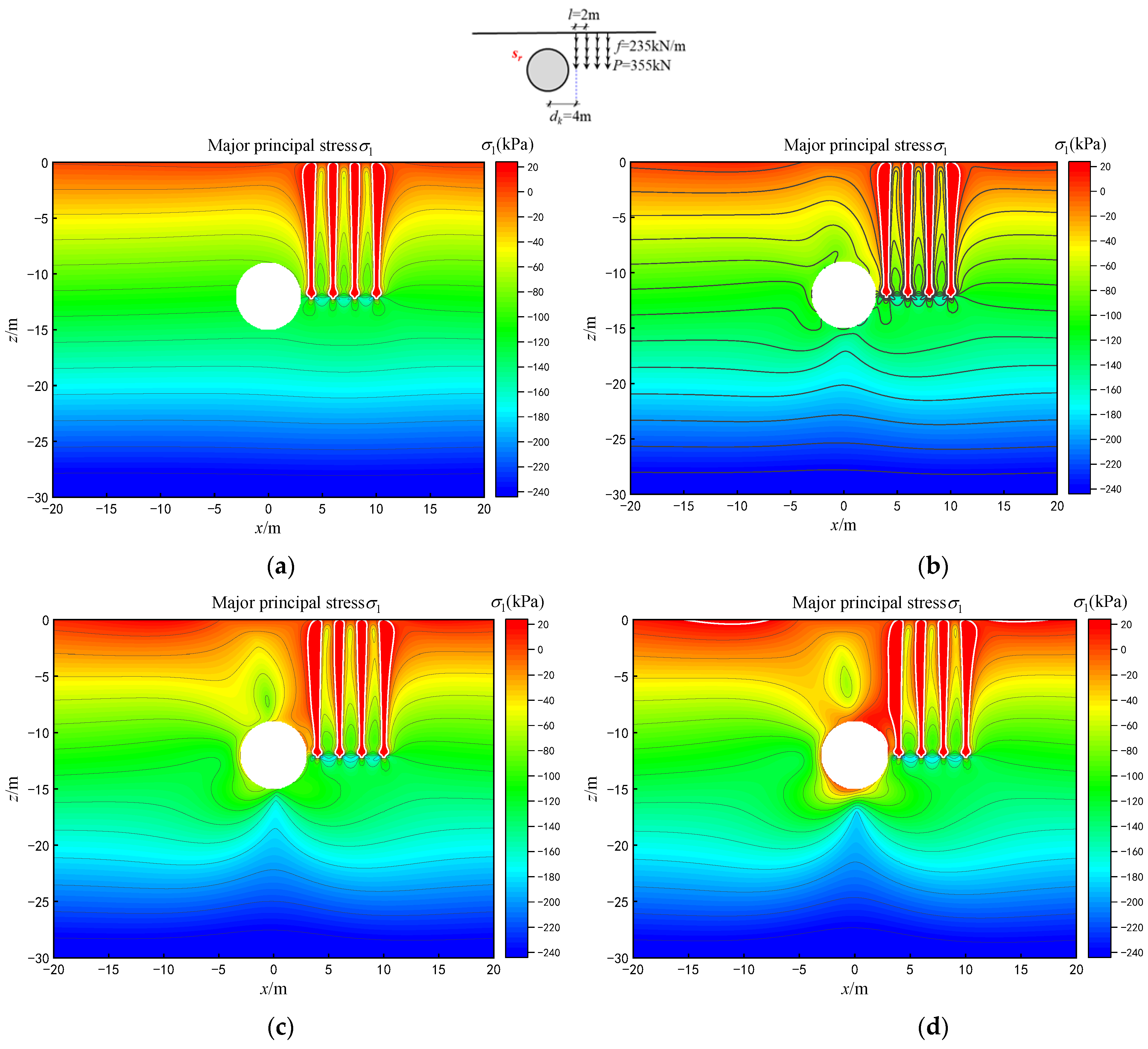
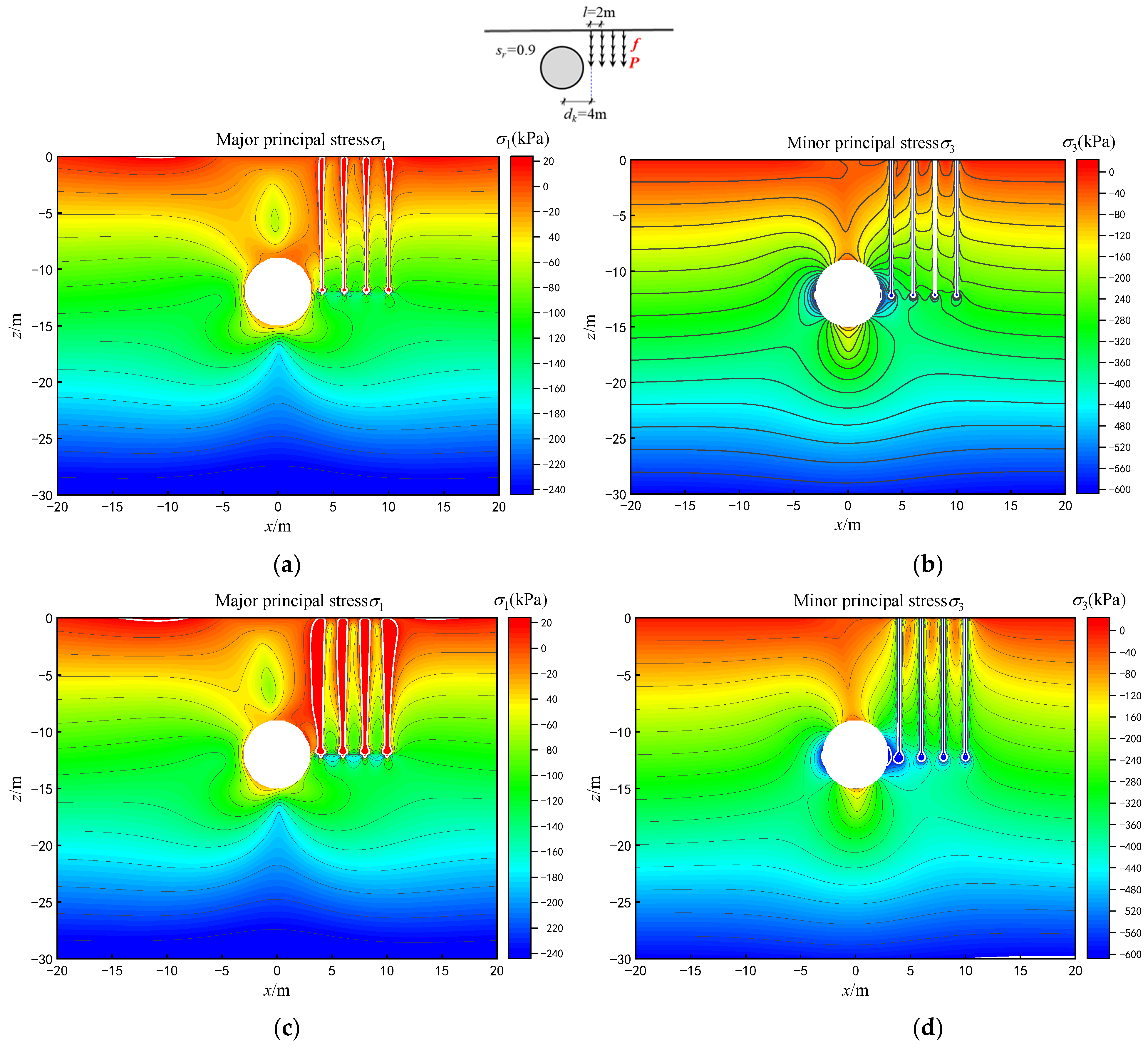
4. Parametric Analysis

In this section, a parametric analysis with regard to the influences of different parameters on the stress and potential plastic zone of the ground is deliberated; these parameters are the soil parameters, pile parameters and the stress release degree of the tunnel periphery. We established some basic parameters: (1) the geometrical parameters of the tunnel are radius r = 3 m, depth H = 12 m; (2) the soil parameters are a Young’s modulus of E = 20 MPa and a Poisson’ s ratio of ν = 0.3; (3) the pile parameters are considered as the number of piles m = 4.

4.1. Stress Analysis

With regard to the influences of the stress release function in Equation (10) on the ground stress, the contour diagrams of major principal stress under different sr values are presented in Figure 7, wherein the pile group loads are 4 m to the right side of the tunnel.
Considering the plane strain condition, the major and minor principal stresses are
σ 1 = σ x + σ z 2 + ( σ x σ z 2 ) 2 + σ x z 2
σ 3 = σ x + σ z 2 ( σ x σ z 2 ) 2 + σ x z 2
The stress around the tunnel is in the initial stress state when the stress release coefficient equals 0; moreover, the stress field around the pile group is symmetrical about the vertical centerline of the pile group due to the existence of the loads, as shown in Figure 7a. The tensile stress zone is mainly concentrated on the ground surface and pile group when sr is small, as shown in Figure 7b. With the increase in the value of sr, the tensile stress zone on the ground surface gradually develops downward as well as beginning to appear on the upper right side of the tunnel, due to the influence of the pile group load (see Figure 7d). The greater the value of sr, the greater the disturbance of the stratum stress field.
Figure 8 shows the stresses field with various pile group tip loads P and shaft shear loads f. Clearly, the compressive stress zone of   σ 3   mainly appears at the arch waist on both sides of the tunnel, and owing to the influence of the pile group loads, the compressive stress zone on the right side is larger. It can be noted from Figure 8a,b that the stratum stress field is less disturbed when the pile group load is small. The greater the pile group tip loads and shaft shear loads, the greater the degree of stratum disturbance.
Figure 9 provides the stress distribution of major principal stresses with various pile lengths and relative positions of the pile group and tunnel. As shown in Figure 9a, the pile group is located 1 m above the tunnel crown, and the stratum stress is disturbed in the horizontal range of approximately −5 m~5 m (h = 8 m, l = 2 m). Compared with bottom of pile group, the compressive stress on both sides of the tunnel above the pile group tip is smaller than that in Figure 9b. Moreover, it may also be noted from Figure 9c,d that the disturbed range of stratum stress increases with the increase in pile length. Meanwhile, the tensile stress zone appears at the upper right of the tunnel.

4.2. Analysis of Potential Plastic Zone

Consequently, the method proposed in this paper can also introduce prediction of a potential plastic zone. In this way, we can solve not only the ground stress distribution but also the potential plastic zone, which provides a more intuitive way to ensure the safety of tunnel construction and existing structures.
Based on the Mohr–Coulomb yield criterion, combining Equation (26) as well as Equation (27), the judgment equation of potential plastic zone induced by tunneling with adjacent pile group loads in a gravity field can be obtained as Equation (28). The stress in the potential plastic zone meets τ 0 τ f .
τ 0 τ f = c σ tan φ
where c and φ are the soil’s cohesion and internal friction angle, respectively,
τ 0 = ( σ 1 σ 3 ) 2 cos φ ,   σ = σ 1 + σ 3 2 + ( σ 1 σ 3 ) 2 sin φ .

4.2.1. Influence of the Pile Group

In this section, the control parameters are assumed to be r = 3 m, H = 12 m, sr = 0.9, h = 12 m, P = 355 kN, f = 235 kN/m, γ = 20 kN/m3, c = 40 kPa, φ = 20°. Figure 10 plots the potential plastic zones for different offsets dk, and the potential plastic zones are merged in Figure 10a. It can be noted from Figure 10b that the potential plastic zone of the tunnel begins separated from the potential plastic zone of the pile group when dk = 7 m. Furthermore, the degree of separation increases gradually with the increase in the value of dk, as shown in Figure 10c,d; In Figure 10e, the potential plastic zone of the tunnel and pile group are completely separated when dk = 10 m; however, there is some influence between them; In Figure 10d, the potential plastic zone of the tunnel is almost not affected by the pile group, and the potential plastic zone of the tunnel is approximately symmetrical when dk = 12 m.
Moreover, the aforementioned analysis suggests that the potential plastic zone induced by tunneling is butterfly shaped when the gravity field is involved; however, the shape of the potential plastic zone is circular when the gravity field is not involved [34].

4.2.2. Influence of Soil Parameters

Figure 11 shows the influence of different soil parameters on the ranges of the potential plastic zones. The influence of four different magnitudes of volumetric weight of soil on the ranges of the potential plastic zones is shown in Figure 11a. The results indicate that the potential plastic zones of the pile group and tunnel coalesce, and the range of the potential plastic zone increases as the volumetric weight increases. The influence of different soil cohesion (c = 35 kPa, 45 kPa, 55 kPa and 65 kPa) on the range of the potential plastic zone is plotted in Figure 11b. Figure 11c particularly presents the influence of different magnitudes of the angle of internal friction (φ = 20°, 25°, 30°, and 40°) on the range of the potential plastic zone. It is worth noting that the influence rules of c and φ are similar to each other, based on Figure 11b,c. Moreover, it can be observed that the butterfly shape of the potential plastic zone is obvious at a relatively low cohesion value or a low angle of internal friction of the soil.
In this paper, a theoretical calculation procedure is developed for prediction of the secondary stress field and the related potential plastic zone caused by tunneling adjacent to crossing existing building/structures foundations. The working conditions set in this paper are very common in practical projects, and rely on the background project of a section of the Beijing subway adjacent to the bridge pile foundations, which is a typical working condition. To address this problem, most scholars currently use numerical methods and model test methods to predict the influence of tunneling in the vicinity of pile foundations in soils. In the light of this, this study provides a theoretical analysis method for this type of engineering, which is important for understanding the generation mechanisms of stress and deformation, and is able to study the basic relationship between different variables and parameters involved in this type of problem. Moreover, this study more comprehensively considers the influence of stress release sr, the relative distance dk between pile group and tunnel, the pile length h, the pile loads P and f, and soil parameters (γ, c, φ ). The working conditions match the real working conditions, so based on the established procedures, incorporating engineering parameters will allow us to qualitatively predict the secondary stress field and potential plastic zone. In future related research, a coupling analysis with analytical solutions and the additional effects of adjacent structures will be proposed to consider more complex underground space structures. The reasonable boundary condition is a key factor.

5. Conclusions

Herein, new analytical solutions have been proposed to predict ground responses caused by tunneling alongside existing pile group loads in the interior of the stratum in a gravity field. The stress-release function is proposed to reflect the stress release behavior of the tunnel periphery during excavation, which makes it a good tool to more accurately describe ground responses under different degrees of stress release. The following conclusions of this work have been drawn.
(1)
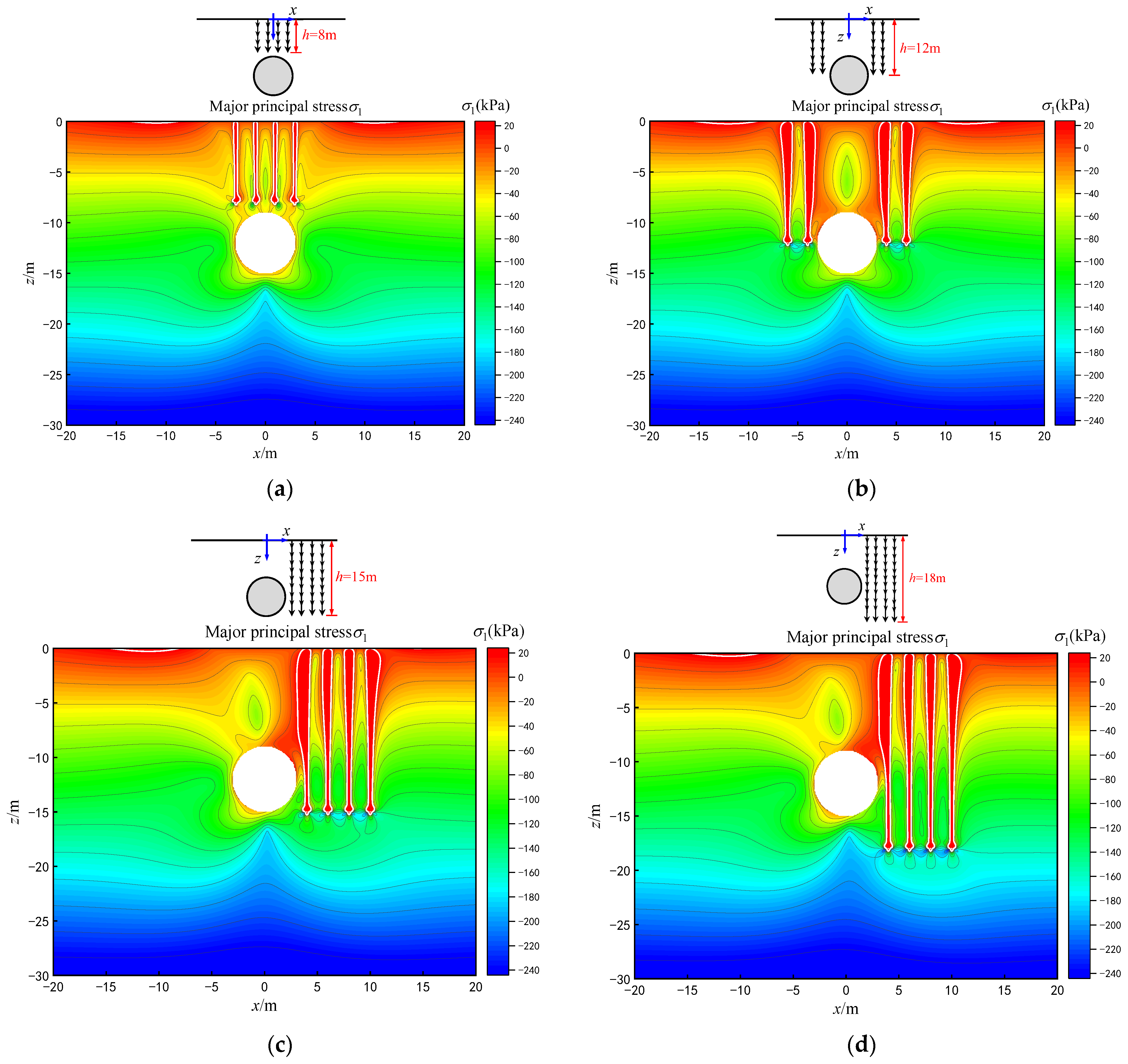
The stress around the tunnel is greatly affected by a change in the stress release coefficient. When the sr is large enough, the tensile stress zone appears in the tunnel crown; notably, the tensile stress zone appears at the right of the tunnel crown due to the influence of pile group loads. The greater the pile group tip loads and shaft shear loads, the greater the degree of stratum disturbance.
(2)
The stratum stress is disturbed in the horizontal range of approximately −5 m~5 m (h = 8 m, l = 2 m), when the pile group is located 1 m above the tunnel crown; the disturbed range of stratum stress increases with the increase in pile length.
(3)
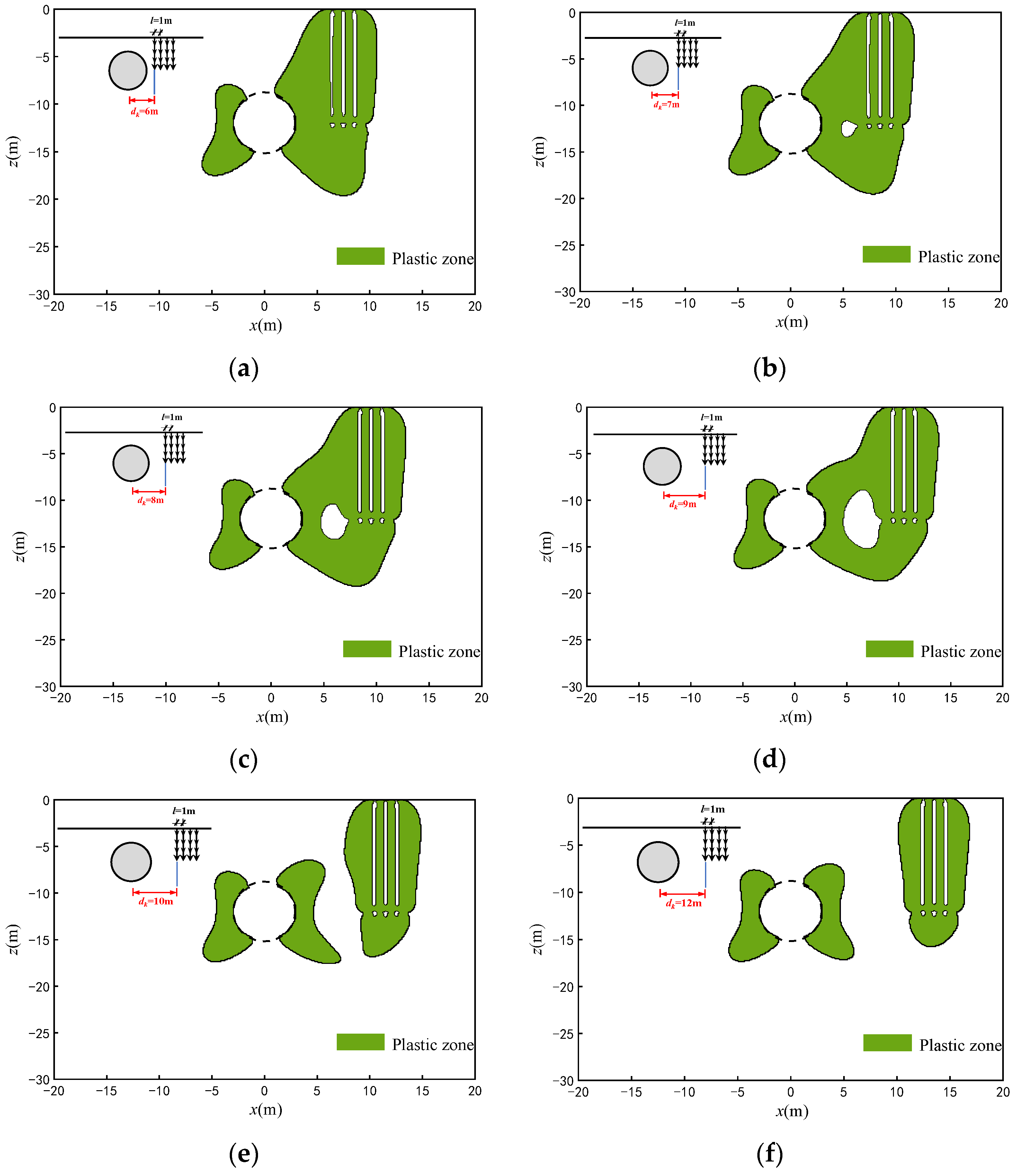
Considering the gravity field, the potential plastic zone of the tunnel is butterfly shaped, and the range of lower part is larger than the upper. The potential plastic zones are merged when the horizontal distance between the pile group and the tunnel dk 3r; the potential plastic zone is completely separated when dk > 3r; the potential plastic zone of the tunnel is almost unaffected by the pile group when dk 4r, and the law of the influence of the relative position of the pile group and tunnel on the plastic zone is consistent with the law presented in Xiang et al. (2013).
(4)
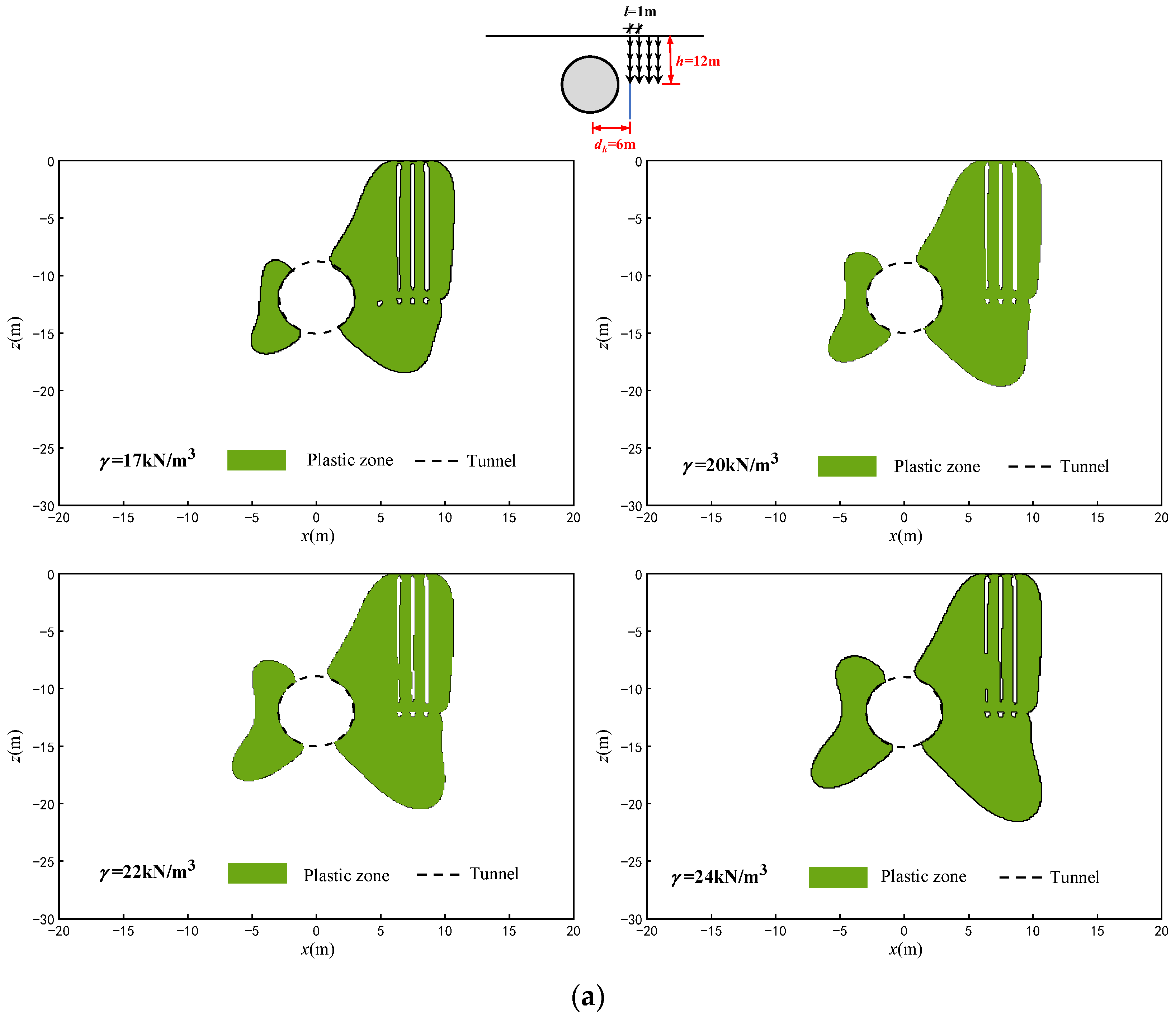
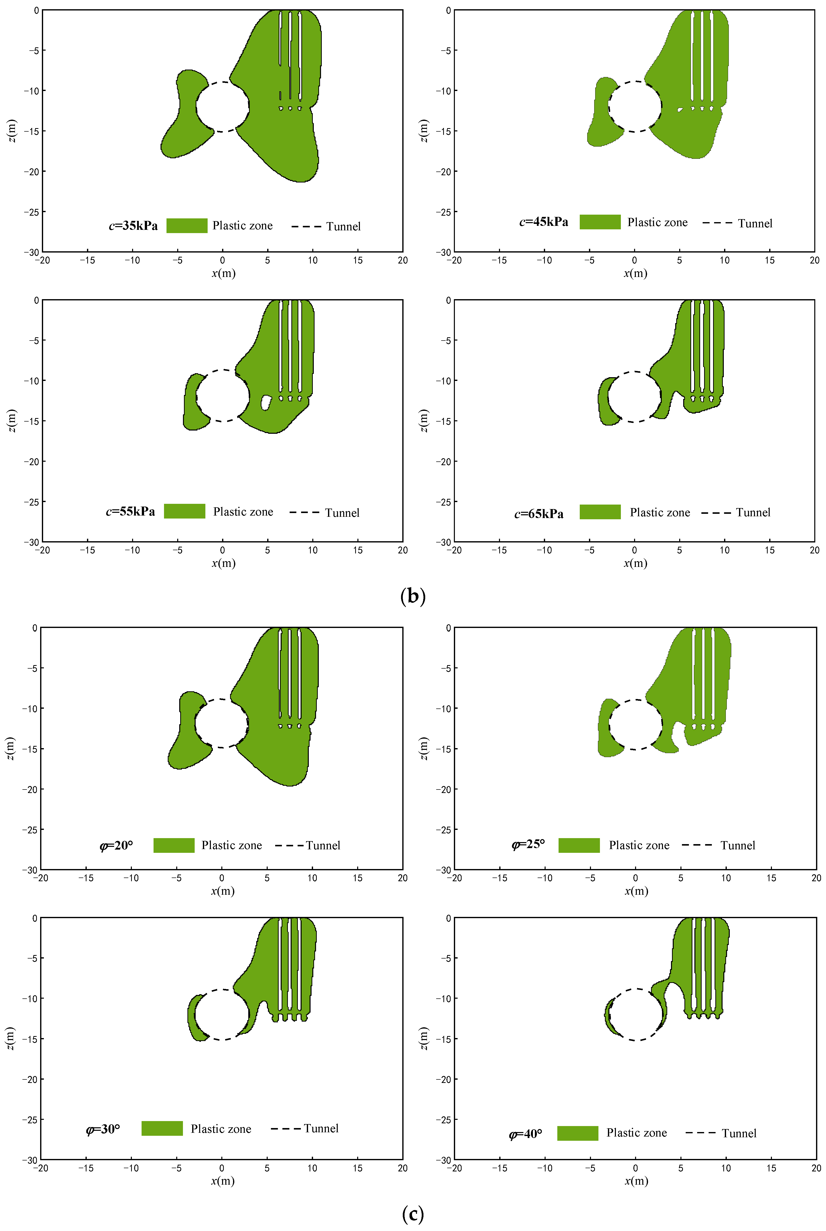
Shear strength parameters have similar influence rules on the potential plastic zone, and the ranges of the potential plastic zone decrease as the c and φ increase; on the contrary, the ranges of the potential plastic zone increase as the volumetric weight increases.
Because this study does not consider the lining effect, the result of such an analysis is biased towards safety. The solutions provide a simple and effective approach to quickly estimate the stability of shallow tunnels and minimize the risk of damage as a result of tunnel construction under the conditions of existing pile group loads in the planning stage.

Author Contributions

Conceptualization, C.G. and F.K.; Methodology, C.G., F.K. and D.L.; Software, Y.T.; Validation, Y.T.; Formal analysis, Y.T. and L.S.; Investigation, Y.T. and L.S.; Writing—original draft, C.G.; Writing—review & editing, F.K. and D.L.; Visualization, L.S.; Supervision, X.D.; Project administration, X.D.; Funding acquisition, C.G. All authors have read and agreed to the published version of the manuscript.

Funding

This research was funded by the National Key R&D Program of China (Grant No. 2022YFC3800901), the National Natural Science Foundation of China (Grant No. 52278385), and the Beijing Municipal Education Commission (Grant No. KM202210005019).

Data Availability Statement

Data sharing not applicable.

Conflicts of Interest

The authors declare no conflict of interest.

References

  1. Guo, C.; Fan, L.; Han, K.; Li, P.; Zhang, M. Progressive failure analysis of shallow circular tunnel based on the functional catastrophe theory considering strain softening of surrounding rock mass. Tunn. Undergr. Space Technol. 2023, 131, 104799. [Google Scholar] [CrossRef]
  2. Huang, Z.K.; Zhang, D.M.; Pitilakis, K.; Tsinidis, G.; Argyroudis, S. Resilience assessment of tunnels: Framework and application for tunnels in alluvial deposits exposed to seismic hazard. Soil Dyn. Earthq. Eng. 2022, 162, 107456. [Google Scholar] [CrossRef]
  3. Kong, F.C.; Lu, D.C.; Ma, Y.D.; Tian, T.; Yu, H.T.; Du, X.L. Novel hybrid method to predict the ground-displacement field caused by shallow tunnel excavation. Sci. China Technol. Sci. 2023, 66, 101–114. [Google Scholar] [CrossRef]
  4. Zhang, J.Z.; Phoon, K.K.; Zhang, D.M.; Huang, H.W.; Tang, C. Novel approach to estimate vertical scale of fluctuation based on CPT data using convolutional neural networks. Eng. Geol. 2021, 294, 106342. [Google Scholar] [CrossRef]
  5. Zhao, Y.; Chen, X.; Hu, B.; Wang, P.; Li, W. Evolution of tunnel uplift induced by adjacent long and collinear excavation and an effective protective measure. Tunn. Undergr. Space Technol. 2023, 131, 104846. [Google Scholar] [CrossRef]
  6. Cao, L.Q.; Chen, X.S.; Zhang, D.L.; Su, D. Theoretical investigation of restraint effect of isolation piles on vertical ground displacements due to tunneling under the plane state. Chin. J. Geotech. Eng. 2022, 44, 916–925. (In Chinese) [Google Scholar]
  7. Chapman, D.N.; Rogers, C.D.F.; Hunt, D.V.L. Predicting the settlements above twin tunnels constructed in soft ground. Tunn. Undergr. Space Technol. 2004, 19, 378. [Google Scholar]
  8. Fang, Q.; Zhang, D.L.; Li, Q.Q.; Wong, L.N.Y. Effects of twin tunnels construction beneath existing shield-driven twin tunnels. Tunn. Undergr. Space Technol. 2015, 45, 128–137. [Google Scholar] [CrossRef]
  9. Lu, D.C.; Lin, Q.T.; Tian, Y. Formula for predicting ground settlement induced by tunnelling based on Gaussian function. Tunn. Undergr. Space Technol. 2020, 103, 103443. [Google Scholar] [CrossRef]
  10. Peck, R.B. Deep excavations and tunnelling in soft ground. In Proceedings of the International Conference on Soil Mechanics and Foundation Engineering, State-of-the-Art, Mexico City, Mexico, 25–29 August 1969; pp. 225–290. [Google Scholar]
  11. Huang, M.S.; Li, Z.; Yang, C. Analysis of the shielding effect of a pile group adjacent to tunneling. China Civil. Eng. J. 2007, 40, 69–74. (In Chinese) [Google Scholar]
  12. Lee, C.J.; Bolton, M.D.; Tabbaa, A.A. Numerical modeling of group effects on the distribution of dragloads in pile foundations. Géotechnique 2002, 52, 325–335. [Google Scholar] [CrossRef]
  13. Zhu, F.B.; Yang, P.; Ong, C.W. Numerical analysis on influence of shield tunnel excavation to neighboring piles. Chin. J. Geotech. Eng. 2008, 30, 298–302. (In Chinese) [Google Scholar]
  14. Lee, Y.J.; Banssett, R.H. Influence zones for 2D pile-soil-tunneling interaction based on model test and numerical analysis. Tunn. Undergr. Space Technol. 2007, 22, 325–342. [Google Scholar] [CrossRef]
  15. Lu, D.C.; Kong, F.C.; Du, X.L.; Shen, C.P.; Gong, Q.M.; Li, P.F. A unified displacement function to analytically predict ground deformation of shallow tunnel. Tunn. Undergr. Space Technol. 2019, 88, 129–143. [Google Scholar] [CrossRef]
  16. Verruijt, A. A complex variable solution for a deforming circular tunnel in an elastic half-plane. Int. J. Numer. Anal. Methods GeoMech. 1997, 21, 77–89. [Google Scholar] [CrossRef]
  17. Zhang, Z.; Wo, W.; Mu, L.; Chen, J.; Zhu, Z.; Pan, Y. Mathematical modelling for shield tunneling induced displacement effects on in-service tunnel: Theoretical solution including shearing deformation of segment and stiffness reduction of circumferential joints. Appl. Math. Model. 2023, 118, 322–345. [Google Scholar] [CrossRef]
  18. Bobet, A. Analytical solutions for shallow tunnels in saturated ground. J. Eng. Mech. 2001, 127, 1258–1266. [Google Scholar] [CrossRef]
  19. Li, P.F.; Gou, B.L.; Zhu, M.; Gao, X.J.; Guo, C.X. Calculation method of time-dependent behavior for tunneling-induced ground movements based on virtual image technique. Rock Soil Mech. 2022, 43, 799–807. (In Chinese) [Google Scholar]
  20. Sagaseta, C. Analysis of undrained soil deformation due to ground loss. Geotechnique 1987, 37, 301–320. [Google Scholar] [CrossRef]
  21. Howland, R.C.J.; Knight, R.C. Stress functions for a plate containing groups of circular holes. Philos. Trans. R. Soc. Lond. Ser. A Math. Phys. Sci. 1939, 238, 357–392. [Google Scholar]
  22. Radi, E. Path-independent integrals around two circular holes in an infinite plate under biaxial loading conditions. Int. J. Eng. Sci. 2011, 49, 893–914. [Google Scholar] [CrossRef]
  23. Verruijt, A. Deformations of an elastic half plane with a circular cavity. Int. J. Solid Struct. 1998, 35, 2795–2804. [Google Scholar] [CrossRef]
  24. Verruijt, A.; Strack, O.E. Buoyancy of tunnels in soft soils. Géotechnique 2008, 58, 513–515. [Google Scholar] [CrossRef]
  25. Zhang, Z.; Huang, M.; Pan, Y.; Li, Z.; Ma, S.; Zhang, Y. Time-dependent analyses for ground movement and stress field induced by tunnelling considering rainfall infiltration mechanics. Tunn. Undergr. Space Technol. 2022, 122, 104378. [Google Scholar] [CrossRef]
  26. Kong, F.C.; Lu, D.C.; Ma, C.; Shen, C.P.; Yang, X.D.; Du, X.L. Fractional viscoelastic solution of stratum displacement of a shallow tunnel under the surface slope condition. Undergr. Space 2023, 10, 233–247. [Google Scholar] [CrossRef]
  27. Zhang, Z.; Huang, M.; Xi, X.; Yang, X. Complex variable solutions for soil and liner deformation due to tunneling in clays. Int. J. Geomech. 2018, 18, 04018074. [Google Scholar] [CrossRef]
  28. Lu, A.Z.; Zeng, X.T.; Xu, Z. Solution for a circular cavity in an elastic half plane under gravity and arbitrary lateral stress. Int. J. Rock Mech. Min. Sci. 2016, 89, 34–42. [Google Scholar] [CrossRef]
  29. Lu, A.; Cai, H.; Wang, S. A new analytical approach for a shallow circular hydraulic tunnel. Meccanica 2019, 54, 223–238. [Google Scholar] [CrossRef]
  30. Kong, F.C.; Lu, D.C.; Du, X.L.; Li, X.Q.; Su, C.C. Analytical solution of stress and displacement for a circular underwater shallow tunnel based on a unified stress function. Ocean Eng. 2021, 219, 108352. [Google Scholar] [CrossRef]
  31. Wang, H.N.; Chen, X.P.; Jiang, M.J.; Song, F.; Wu, L. The analytical predictions on displacement and stress around shallow tunnels subjected to surcharge loadings. Tunn. Undergr. Space Technol. 2018, 71, 403–427. [Google Scholar] [CrossRef]
  32. Yang, G.; Zhang, C.; Min, B.; Chen, W. Complex variable solution for tunneling-induced ground deformation considering the gravity effect and a cavern in the strata. Comput. Geotech. 2021, 135, 104154. [Google Scholar] [CrossRef]
  33. Marshall, A.M.; Haji, T. An analytical study of tunnel-pile interaction. Tunn. Undergr. Space Technol. 2015, 45, 43–51. [Google Scholar] [CrossRef] [Green Version]
  34. Xiang, Y.; Feng, S. Theoretical prediction of the potential plastic zone of shallow tunneling adjacent to pile foundation in soils. Tunn. Undergr. Space Technol. 2013, 38, 115–121. [Google Scholar] [CrossRef]
  35. Guo, C.; Qi, J.; Shi, L.; Fang, Q. Reasonable overburden thickness for underwater shield tunnel. Tunn. Undergr. Space Technol. 2018, 81, 35–40. [Google Scholar] [CrossRef]
  36. Shang, H.S.; Zhang, H.; Liang, F.Y. Lateral bearing capacity of pile foundation due to shallow tunneling. Chin. J. Geotech. Eng. 2013, 35, 740–743. (In Chinese) [Google Scholar]
  37. Zhang, J.Z.; Huang, H.W.; Zhang, D.M.; Phoon, K.K.; Liu, Z.Q.; Tang, C. Quantitative evaluation of geological uncertainty and its influence on tunnel structural performance using improved coupled Markov chain. Acta Geotech. 2021, 16, 3709–3724. [Google Scholar] [CrossRef]
  38. Zhao, Y.; Chen, X.; Hu, B.; Huang, L.; Li, W.; Fan, J. Evolution of tunnel uplift and deformation induced by an upper and collinear excavation: A case study from Shenzhen metro. Transp. Geotech. 2023, 39, 100953. [Google Scholar] [CrossRef]
  39. Mindlin, R.D. Force at a point in the interior of a semi-infinite solid. Physics 1936, 7, 195–202. [Google Scholar] [CrossRef]
  40. Strack, O.E.; Verruijt, A. A complex variable solution for a deforming buoyant tunnel in a heavy elastic half-plane. Int. J. Numer. Anal. Methods GeoMech. 2002, 26, 1235–1252. [Google Scholar] [CrossRef]
Figure 1. Mechanical analysis model of shallow tunnel adjacent to pile group.
Mathematics 11 01608 g001
Figure 2. Flowchart of the calculation.
Mathematics 11 01608 g002
Figure 3. General boundary conditions of mechanical model.
Mathematics 11 01608 g003
Figure 4. Disassembly of boundary conditions.
Mathematics 11 01608 g004
Figure 5. Stress at a point Q on the circular tunnel periphery.
Mathematics 11 01608 g005
Figure 6. ζ -plane of conformal mapping.
Mathematics 11 01608 g006
Figure 7. Contour diagrams of major principal stresses with various sr: (a) sr = 0; (b) sr = 0.3; (c) sr = 0.7; (d) sr = 1.
Mathematics 11 01608 g007
Figure 8. Contour diagrams of major and minor principal stresses with various pile group tip loads P and shaft shear loads f when sr = 0.9: (a,b) P = 150 kN, f = 70 kN/m; (c,d) P = 355 kN, f = 235 kN/m.
Mathematics 11 01608 g008
Figure 9. Contour diagrams of major principal stresses with various pile lengths and relative positions of the pile group and tunnel when sr = 0.9: (a) the pile group right on top of the tunnel; (b) the pile group distributed on both sides of the tunnel; (c) the depth of the pile group tip close to the tunnel spring line; (d) the depth of the pile group tip deeper than the tunnel spring line.
Mathematics 11 01608 g009
Figure 10. Potential plastic zones for different offsets dk of the pile group from the tunnel: (a) dk = 6 m; (b) dk = 7 m; (c) dk = 8 m; (d) dk = 9 m (e) dk = 10 m; (f) dk = 12 m.
Mathematics 11 01608 g010
Figure 11. Potential plastic zones for different soil parameters when d1 = 6 m, d2 = 7 m, d3 = 8 m, d4 = 9 m (x coordinate of each pile) and h = 12 m. (a) Different magnitudes of volumetric weight; (b) Different magnitudes of cohesion; (c) Different magnitudes of the angle of internal friction.
Mathematics 11 01608 g011aMathematics 11 01608 g011b
Disclaimer/Publisher’s Note: The statements, opinions and data contained in all publications are solely those of the individual author(s) and contributor(s) and not of MDPI and/or the editor(s). MDPI and/or the editor(s) disclaim responsibility for any injury to people or property resulting from any ideas, methods, instructions or products referred to in the content.

