1. Introduction
In recent years, the cessation of production and the abandonment of oil and gas wells due to wellbore integrity damage frequently occurs, and the problem of wellbore integrity has attracted more attention [
1,
2,
3,
4,
5]. The wellbore system involves tubing, casing, wellhead, packer, and more. Among them, the casing string is an important downhole tool to protect the borehole, reinforce the wellbore, isolate the oil, gas, and water layers, and seal various complex formation; it is also the key barrier of wellbore integrity. Therefore, its failure will pose a serious threat to production safety. Unfortunately, such failures do exist and are more likely to take place when casing wear takes place, which is caused by the friction between the down-hole tubular string and wellbore wall in complex structure wells [
6].
Collapse is one of the common failure modes of the casing string under the action of external pressure. There are a lot of researchers working on the mechanism of casing collapse. Both analytical [
7,
8,
9,
10,
11,
12] and finite element methods [
13,
14,
15,
16] have been employed to carry out various studies on casing collapse, leading to the development of a relatively rigorous theoretical system and mature technical methods. However, most of these works focus on the casing body, treating the casing as a uniform round pipe. In fact, the casing string is not only composed of the casing body, but also threaded connections, which connect thousands of meters of casing together and could be the main failure location of the casing string. According to field statistics, 64% of casing failure accidents take place at threaded connections and some wells even reach 86% [
17]. In addition, the failed connections found on the field have serious wear phenomenon [
18], but little attention has been paid to the strength of casing connections. One of the reasons is that the threaded connection has a larger wall thickness compared to the casing body, giving people an impression that the collapse strength of the connection is greater than that of the casing body. The other reason is that the structure of the connection is too complex to analyze. The engaged surface of the pin and box is a three-dimensional spiral surface, which involves strong nonlinearities, making it difficult to carry out the relevant research in depth. In addition, it should be noted that compared to the casing body, the threaded connection has a sealing problem. Chen et al. [
19] established a three-dimensional finite element model of the casing connection and studied the distribution characteristics of contact stress on the joint sealing surface under complex loads. Xu [
4] studied the contact pressure on the sealing surface by an analytical method. The current research on connection sealing are mostly about the contact stress on the sealing surface, but the criterion of seal failure caused by the change of contact stress is not given; the wear phenomenon and how to measure the mechanical properties of the connection under the condition of considering the integrity of the seal are not unified. Under the action of external load, the worn casing connection will have a larger structural deformation and this affects the sealing performance; it is thus necessary to consider the sealing performance when determining the collapse strength. However, this problem has not been received enough attention so far. In this paper, the finite element method was used to calculate the collapse strength of a worn 7” casing connection. Based on the accuracy verification of the model and simulation algorithm, a three-dimensional finite element model of the worn casing connection was proposed to evaluate the collapse strength and the mechanical characteristics of the sealing surface of crescent-worn casing connections. Then, the influence of wear on the sealing integrity was discussed; the collapse strength considering the sealing integrity of the worn casing connection was also assessed using a sealing criterion. Finally, the partition evaluation diagram of collapse strength of the 7” worn casing connection was obtained considering the sealing integrity when wear rates of the casing body and the connection are different.
3. Calculation of Collapse Strength of Crescent-Worn Casing Connection
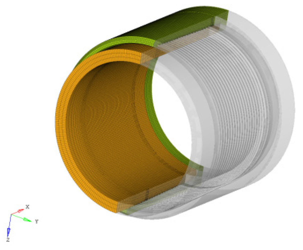
Figure 2 depicts a three-dimensional finite element model of casing connection with P110 steel grade. The specific geometric parameters of casing connection are given in
Table 2.
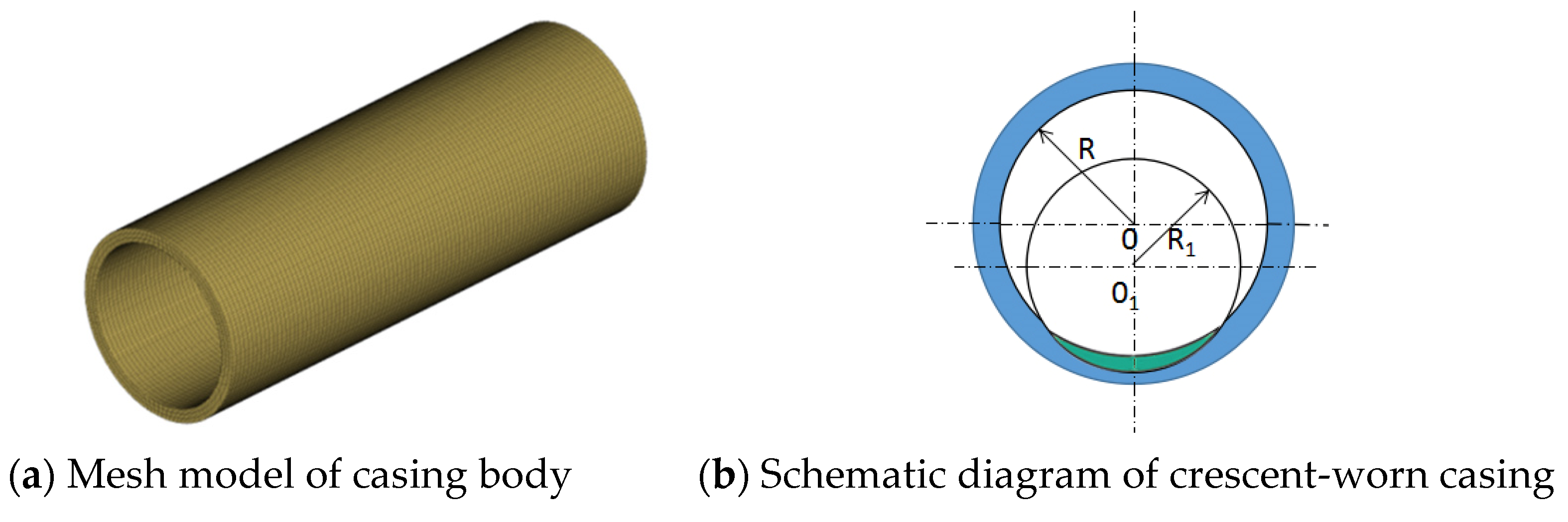
An eight-node hexahedron element was selected to calculate the deformation of above model. The total number of nodes and elements are 604,572 and 495,530, respectively. The mesh was refined in the stress-concentrated parts such as thread teeth and sealing surface. Material properties are the same as those in
Section 2.2. The crescent wear was established on the inner wall of the casing connection, and the wear depth was also 0~4 mm.
To be clear, in this study, the calculation of the casing connection is based on the following assumptions:
- (1)
The basic physical quantities of the box and pin are continuously distributed, such as stress, strain, and displacement;
- (2)
The material of the pin and box of the casing connection adopts the assumption of uniformity and isotropy;
- (3)
Under the action of external force, the casing connection deformation is elastic deformation before the yield load, and plastic deformation after the yield load, without considering the viscosity, creep, and other effects.
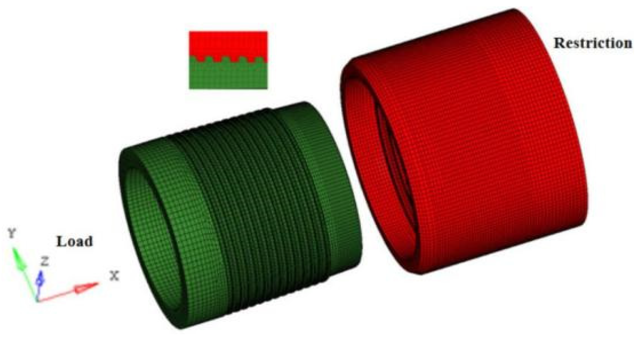
The load was applied by establishing the coupling form of distributing nodes on the end surface of the pin; the constraint was imposed by establishing the coupling form of the kinematical node at the end surface of the box, as shown in
Figure 3. Load cases are shown in
Table 3.
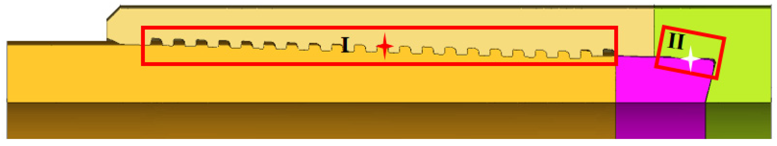
For the convenience of the following description, the section diagram of the connection is given below and the key parts are marked in red boxes, as shown in the
Figure 4. In the figure, zone I represents the engagement area of thread teeth, and zone II represents the sealing surface. The red and white symbols in the zone I and zone II are the locations of the two critical nodes A1 and A2 in the analysis below, and their function and selection will be explained below.
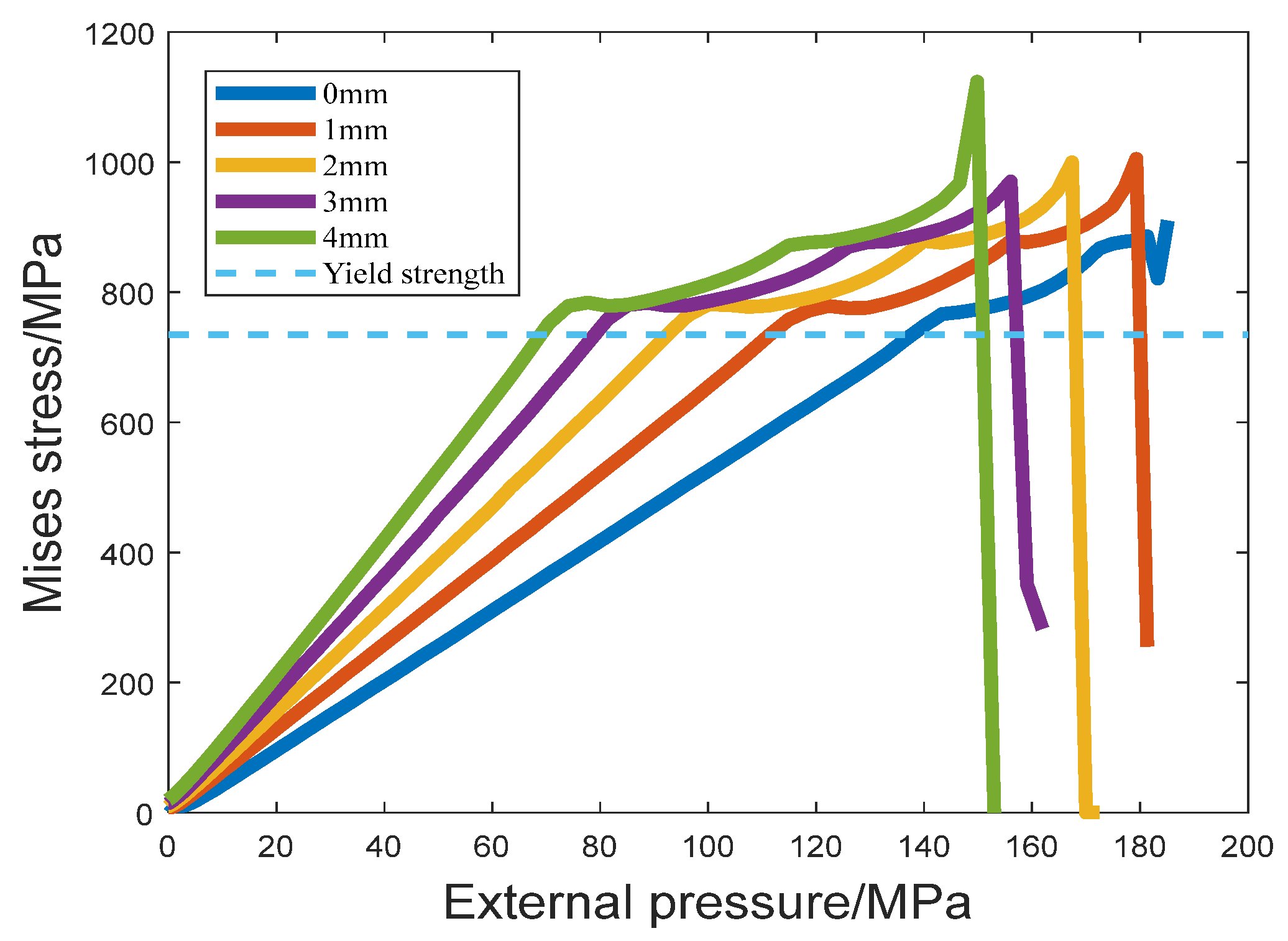
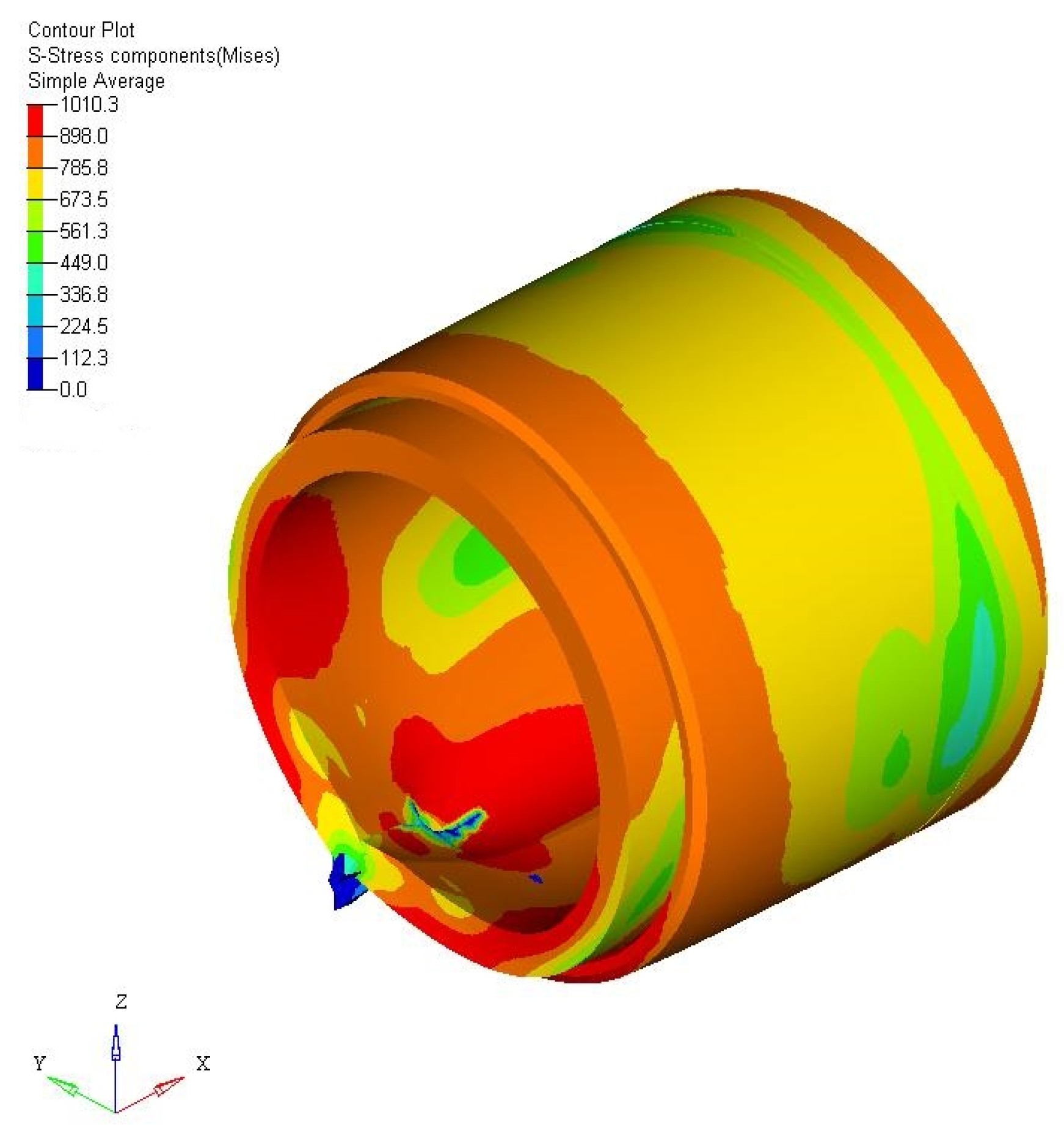
In order to reveal the influence of wear depth on the collapse strength of the casing connection, the von Mises stress curve at a node where the stress is relatively concentrated on the engagement area of thread teeth (corresponding to the red symbol of zone I in
Figure 4) was plotted with the change of external pressure during the increase of wear depth, as shown in
Figure 5. For simplicity, it is referred to as node A1 below.
The external pressure corresponding to the stress reaching the yield strength is getting smaller with increased wear depth, as shown by the blue dotted line in
Figure 5. It is widely known that if a small load increment causes a large increment of the maximum von Mises stress in the finite element calculation, it indicates that the casing connection has lost the ability to resist a further increase of external pressure and the corresponding von Mises stress can be regarded as the collapse strength of the casing connection. The collapse strength of the crescent-worn casing connection is 125.9 MPa, 103.8 MPa, 88.8 MPa, 74.1 MPa, and 63.5 MPa, corresponding to the wear depth of 0mm, 1mm, 2mm, 3mm, and 4mm, respectively. In other words, when crescent wear takes place, the collapse strength of the connection decreases with the increased wear depth. It can be found that under the same wear condition, the collapse strength of the casing connection is slightly greater than that of the casing body shown in
Table 1. This is because the connection is engaged together through the pin and box, and the overall thickness of the connection after engagement is greater than the casing body.
However, wear reduces the collapse strength of the casing connection. When the wear depth reaches 4 mm, the collapse strength of the crescent-worn connection decreases by 49.6% compared with that of the unworn connection. That is to say, when the wear rate reaches about 30%, the collapse strength of the connection is reduced by nearly half. In this case, the casing connection is more likely to collapse, which greatly increases the risk of wellbore integrity damage.
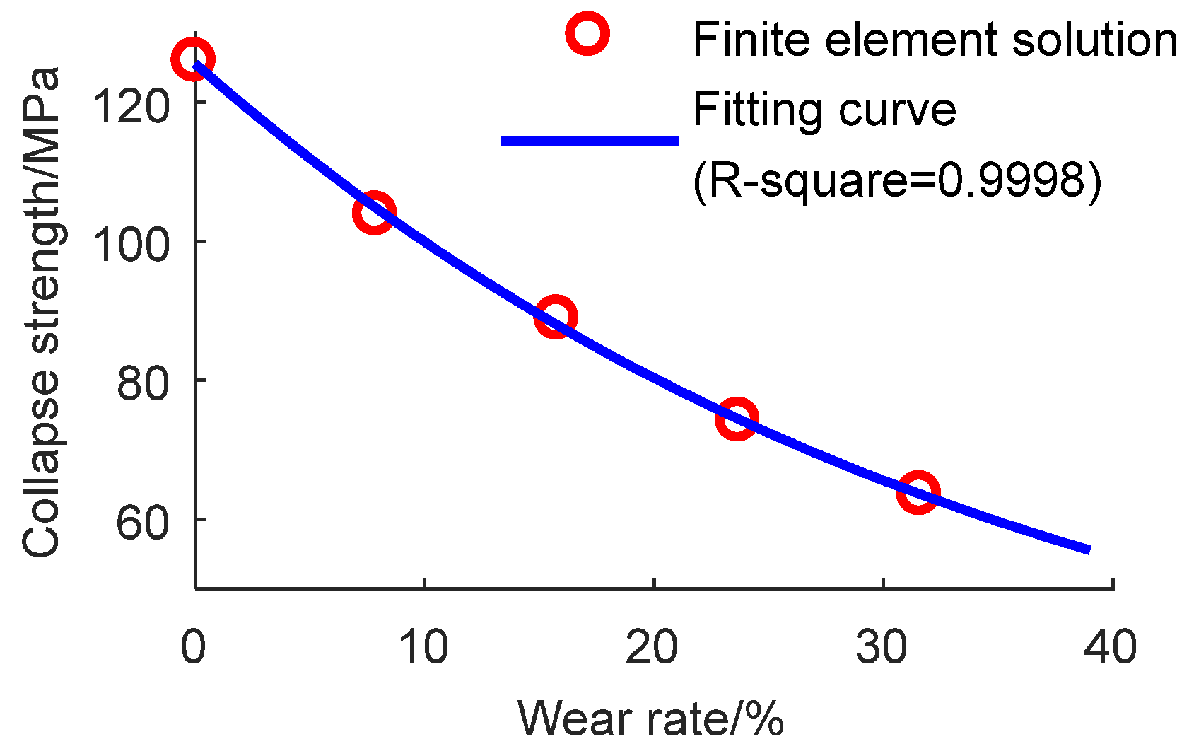
Through curve fitting, the relationship between wear rate and the collapse strength of the crescent-worn casing connection can be obtained:
where
is the wear rate, defined as the ratio of wear depth
to original wall thickness
; and
is the collapse strength of the connection with crescent-worn, MPa.
Figure 6 shows the collapse strength of the worn connection considering the sealing integrity calculated based on the finite element solution and fitting curve drawn by the formula (3).
4. Influence of Wear Depth on Sealing Performance of Connection
Formula (3) is the collapse strength model only considering strength characteristics. However, a very important fact should be recognized, which is that casing connection is not a real thick-wall casing body due to the engagement of the pin and box. Not only its strength but also its sealing performance should be paid attention to under the external pressure. When the casing connection deforms greatly under external load, sealing failure may occur and the integrity of the casing string may be problematic. Therefore, it is more practical to study the casing collapse strength considering the sealing integrity.
Similarly, for the convenience of subsequent analysis and explanation, the diagrams of the critical path are given below, as shown in the
Figure 7.
Figure 7a shows the complete connection and the circumferential path on the sealing surface (corresponding to zone II in
Figure 4). It should be noted that the circumferential path is a ring of sealing ring composed of the node where the maximum contact stress is located along the axial direction on the sealing surface.
Figure 7b shows only the sealing ring of the sealing surface in the connection.
4.1. Axial Distribution Characteristics of Stress on Sealing Surface
The casing connection studied in this paper adopts a sphere-cone sealing structure, as shown in
Figure 8. The sealing is realized by a radial interference fit of the sealing surface and the sealing performance is mainly reflected in the distribution of contact stress on the sealing surface.
A higher contact stress and a larger contact width are the two important features of an excellent sealing performance in the elastic range. The stress on the sealing surface has greatly exceeded the elastic limit. Meanwhile, there is plastic deformation which is helpful to the sealing performance in a certain range. Therefore, it is difficult to accurately describe the micro channel on the sealing surface, which increases the difficulty of evaluating the sealing performance of the sealing surface. In view of both elastic and plastic deformation, fluid leakage will appear in the direction of small leakage resistance, so the fluid leakage resistance is also affected by the contact stress and contact width of the sealing surface. The contact pressure along the axial path on the wear side of the sealing surface was selected (as shown in
Figure 7) to analyze the variation of stress characteristics with different wear depths. The simulation results of the model showed that the width of the sealing surface of the connection corresponding to different wear depths are the same (3.75 mm); thus, only the contact stress on the sealing surface is discussed below.
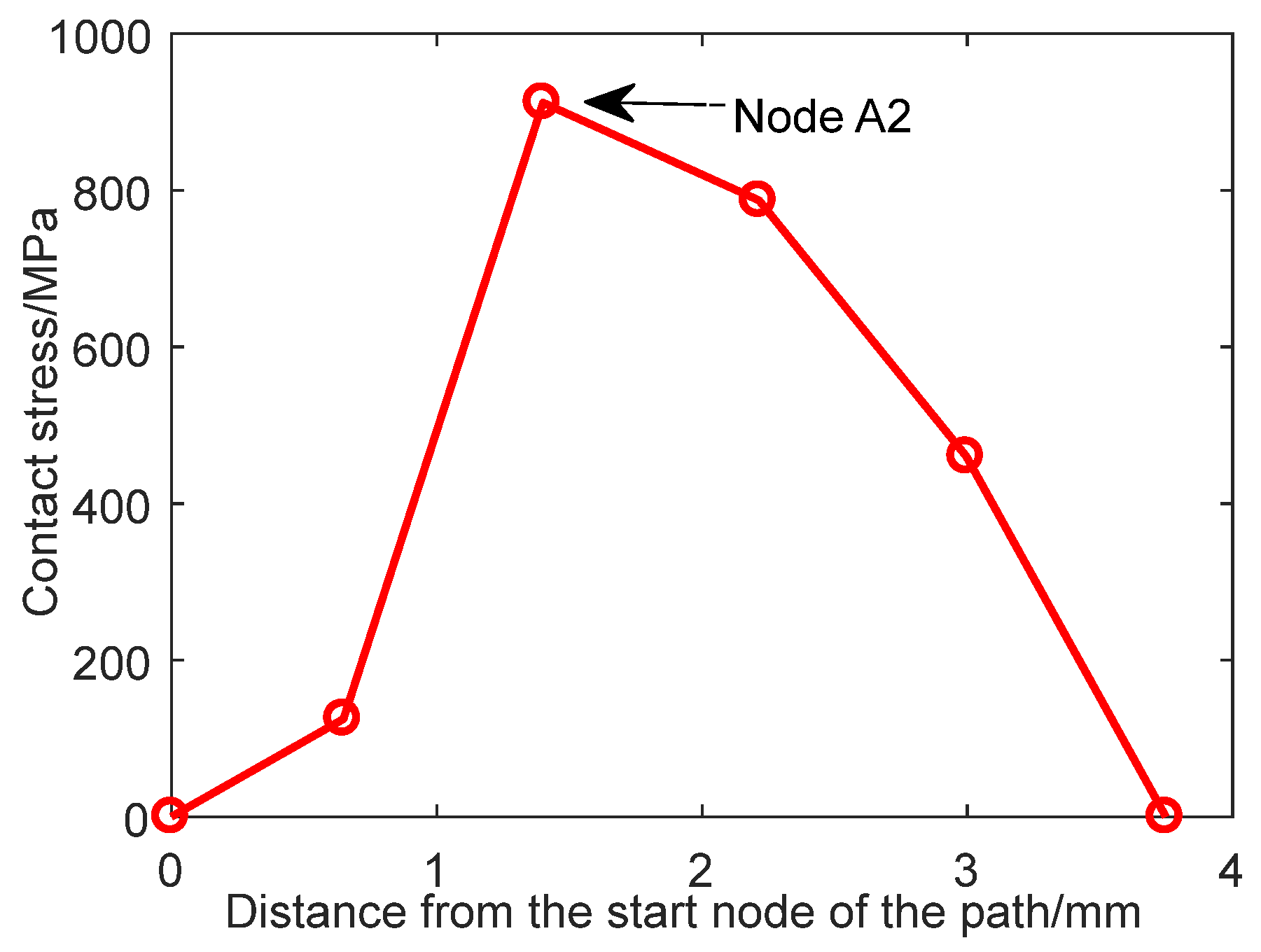
The node with the maximum contact stress on the sealing surface was taken from the axial path (the intersection of the green-color circumferential path and the black-color axial path is shown in
Figure 7b); for simplicity, it is referred to as node A2. Node A2 is the node of maximum stress on the axial path and the critical node for sealing the connection; its location is in the marked white symbol of zone II in
Figure 4. It can be said that the value of contact stress at A2 node determines the sealing quality of the connection, as shown in
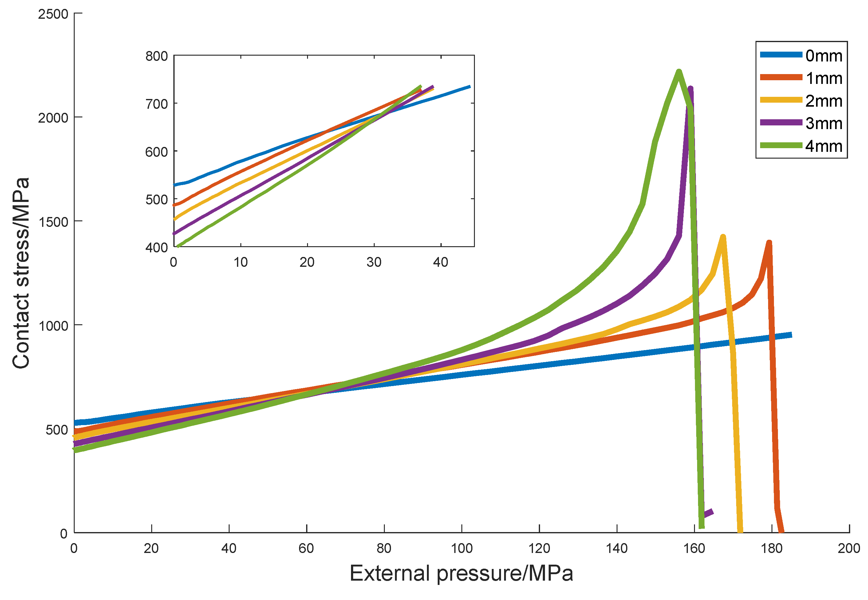
Figure 9. The change of contact stress at this point with external pressure was observed under different wear depths, as shown in
Figure 10.
As can be seen from
Figure 10, with the increase of external pressure, the contact stress on the sealing surface of the casing connection increases gently at first (in the elastic stage), then increases sharply (in the plastic stage), finally dropping rapidly to zero, at which time-step a structural plastic failure has occurred (as shown in
Figure 11). The partially enlarged diagram in
Figure 10 shows that the contact stress on the sealing surface of the pre-tightening connection decreases with the increased wear depth when the external pressure is zero. With the gradual increase of external pressure, the connections with different wear depths reach the yield strength successively. The calculation results show that a greater wear depth corresponds to a smaller external pressure when the contact stress reaches the yield strength—that is, the sealing integrity of the connection decreases.
In order to illustrate the influence of wear on the sealing performance of the connection, the collapse strength of each model calculated in
Section 3 was taken as the dividing line of elastic–plastic, and the average contact stress on the sealing surface of the crescent-worn connection at the elastic stage was obtained, as shown in
Table 4.
It can be found that the average contact stress on the sealing surface of the crescent-worn casing connection decreases gradually with increased wear depth. When the wear depth reaches 4 mm, the average contact stress on the sealing surface is reduced by 16.5%, which reduces the sealing performance of the connection to a certain degree.
4.2. Circumferential Distribution Characteristics of Stress on Sealing Surface
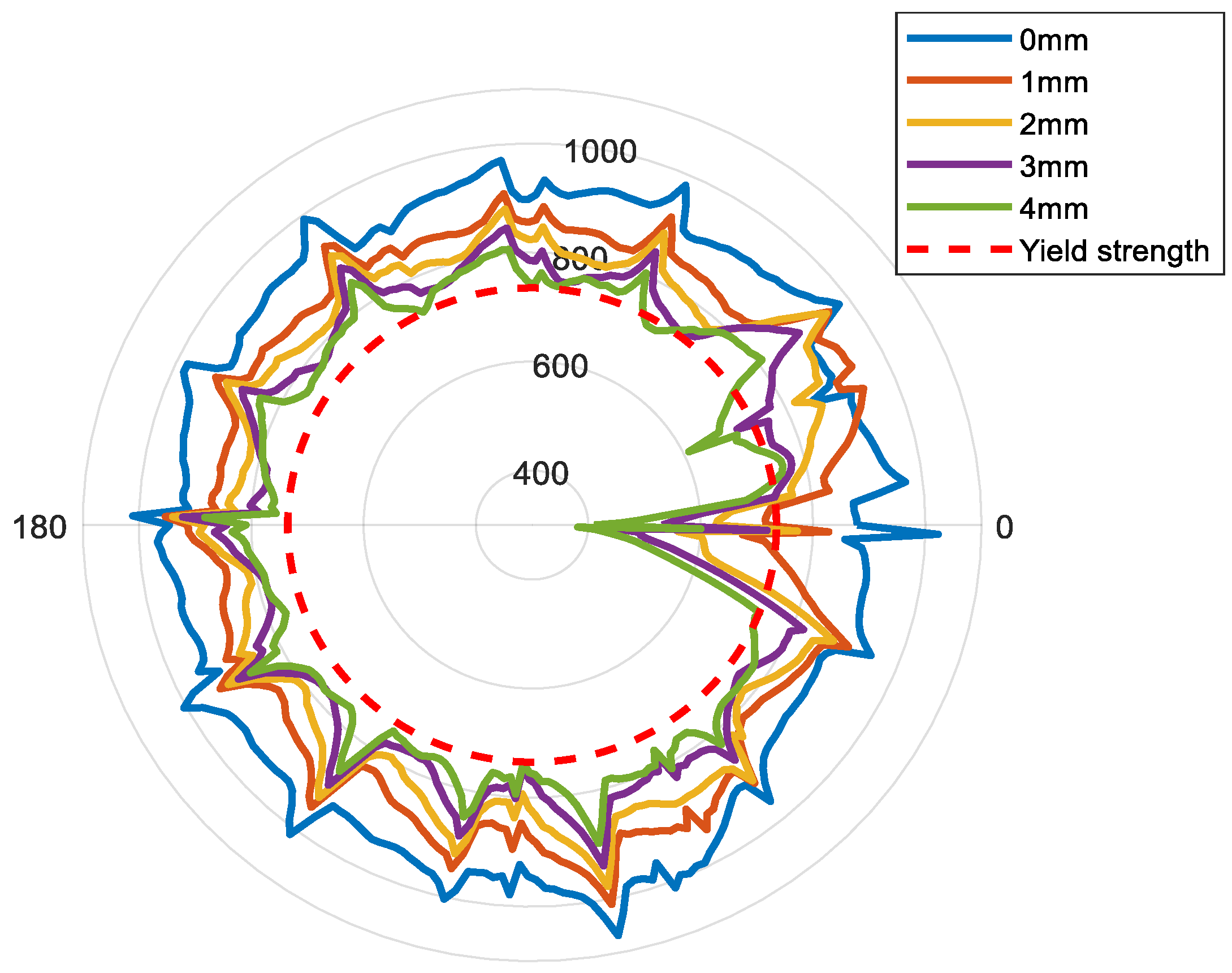
In order to observe the circumferential distribution of contact stress along the sealing surface of the worn connection in the process of increasing external pressure, the circumferential contact stress along the ring (corresponding to the green-color ring in
Figure 7a) on the sealing surface was extracted and expressed in
Figure 12.
It can be found that the stress characteristics along the circumferential path show irregular fluctuations corresponding to each wear depth, which is mainly due to the nonlinear contact characteristics caused by the helix angle of the threaded teeth. With the increase of wear depth, the circumferential contact stress on the sealing surface is gradually decreased, and the contact stress along the circumferential becomes more uneven, which will have an adverse effect on the sealing performance.
As shown in
Table 5, the maximum contact stress, minimum contact stress, and average contact stress on the circumferential path decrease gradually with increased wear depth, and when the wear depth reaches 4 mm, they decrease by 16.2%, 54.9%, and 18.6%, respectively, compared with the unworn connection.
The calculation results show that the maximum contact stress and average contact stress decrease slightly whereas the minimum contact stress decreases greatly. The minimum contact stress on the unworn connection is 845.0 MPa, slightly greater than the yield strength of the material. When the wear depth is 1 mm, the minimum contact stress has decreased to 674.8 MPa, which is lower than the yield strength of the material. With the increase of the wear depth, the minimum contact stress further decreases. When the wear depth is 4 mm, the minimum contact stress decreases by more than half compared with the unworn connection, which is much lower than the yield strength of the material.
Although the maximum contact stress and the average contact stress are both greater than the yield strength under different wear depths, it seems that the connection has reliable sealing performance. Since the contact stress along the circumferential path taken in this paper is the maximum value along the axial path on the whole sealing surface, the minimum contact stress on the circumferential path in
Table 5 is also the maximum contact stress on the axial path where the point is located. Therefore, the minimum contact stress is too much lower than the yield strength of the material, indicating that there may be a leakage channel along the axial path at this position, resulting in connection seal failure. By observing the node of the minimum contact stress on the circumferential path, it was found that the minimum contact stress occurred on the side where the wear occurred under different wear depths, which also proves that the wear has a strong destructive effect on the sealing integrity of the connection.
4.3. Collapse Strength of Worn Casing Connection Considering Sealing Performance
According to the analysis in
Section 4.2, the occurrence of wear reduces the contact stress on the sealing surface of the casing connection and increases the uneven distribution along the circumferential direction, which obviously has an adverse effect on the sealing performance of the connection. Although the worn connection has not been collapsed and sealing failure may have occurred, the obtained collapse strength will be divorced from reality and will have no practical value only considering the collapse strength of the connection without paying attention to the reduction of its sealing performance. Therefore, a calculation model of the collapse strength of the casing connection considering sealing integrity should be proposed.
Based on the theory of sealing contact energy [
21], the flow resistance preventing gas from passing through metal to the metal sealing structure can be characterized by some integral value of contact stress on effective contact width.
When gas seal index > critical gas seal index , there is no Leakage;
When gas seal index < critical gas seal index , leakage takes place.
Murtagian’s experimental results show that the gas seal index of the metal sealing structure with a sphere-cone can be expressed as [
22]:
is the contact stress along the axial path of the wear side of the sealing surface corresponding to the moment of collapse failure occurs, MPa;
is the contact width of the sealing surface, mm; and
is set to 1.2 when sealing compound is used—otherwise, it is set to 1.4.
The critical gas seal index obtained through the experiment test can be expressed as [
22]:
is gas pressure that needs to be sealed, MPa; and
is atmospheric pressure, MPa.
Equations (4) and (5) can be used to obtain the maximum gas pressure in the casing with reliable sealing, which is equivalent to the collapse strength corresponding to seal failure under the action of external pressure.
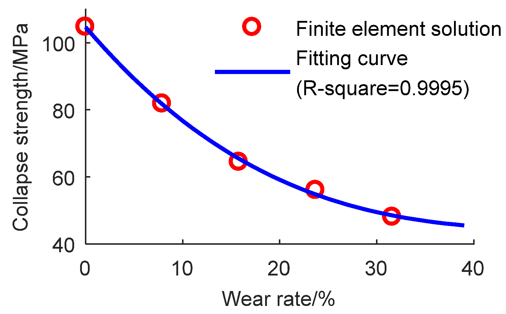
Atmospheric pressure is 0.1 MPa. The collapse strength of the worn connection calculated based on this is 104.7 MPa, 81.8 MPa, 64.4 MPa, 56.0 MPa, and 48.0 MPa, respectively, corresponding to the wear depth of 0 mm, 1 mm, 2 mm, 3 mm, and 4 mm, respectively. Considering the sealing integrity, the relationship between the collapse strength and wear depth of the connection is similar to that of the casing body; that is, with the increase of wear depth, the collapse strength decreases gradually, but the corresponding value decreases slightly. According to the calculated results, the polynomial relationship between wear rate ζ and the collapse strength of the casing connection considering sealing integrity is formulated as follows:
Figure 13 shows the collapse strength of the worn connection considering the sealing integrity calculated based on the finite element solution and fitting curve. Compared with the results in
Section 3, the collapse strength of the connection is greatly reduced after considering the sealing integrity.
5. Discussion
In engineering practice, the sealing integrity of the threaded connection is evaluated by the leakage rate. Leakage rate refers to the leakage rate of medium fluid per second through the sealed interface under standard test conditions. For metal–metal seals, according to the requirements of the threaded connection test procedure of tubing/casing (ISO 13679), the gas leakage rate during the test is less than 0.9 cm
3/15 min, which is an indicator of good sealing [
23]. However, in this study, it is not very possible to quantitatively calculate the leakage rate of the casing connection under wear condition or the collapse strength under critical leakage rate. Therefore, the seal integrity in this article refers to that idea that when the casing string (including casing body and threaded connection) is worn at different degrees, the collapse strength considering the sealing integrity is calculated based on the contact energy theory of the metal seal. This evaluation method considering the sealing integrity of connections makes up for the shortcomings of the current research which only pays attention to the collapse strength in the casing string and ignores the sealing failure of connection. As the weak part of the casing string, the threaded connection is the common site of failure due to a seal problem, so the entire casing string can be considered safe when the safety of the threaded connection is guaranteed.
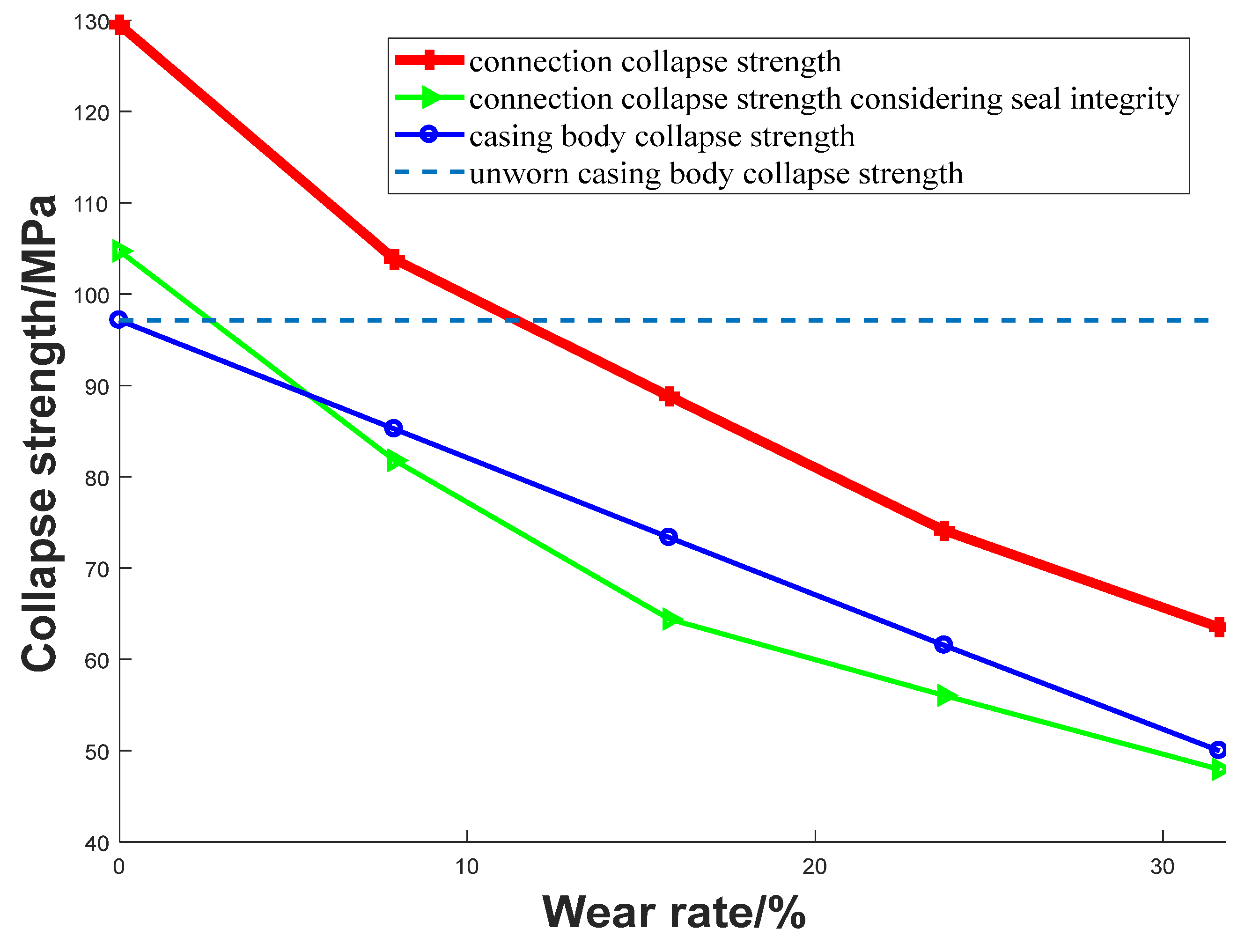
Figure 14 shows the corresponding casing body collapse strength
, casing connection collapse strength
, and casing connection collapse strength considering sealing integrity
. For an unworn connection, the collapse strength is 129.50 MPa, and the collapse strength of the connection considering sealing integrity is 104.74 MPa. For an unworn casing body, its collapse strength is 97.13 MPa, which is lower than connection. At this point, the collapse strength of the connection can be calculated according to the casing body, which is consistent with the current understanding that the collapse strength of the connection is much larger than the casing body.
When the casing body and the connection have the same wear depth, the above conclusion is also established if the sealing integrity is not considered. However, when the wear rate exceeds 5.5% (corresponding to the wear depth of 0.69 mm), the collapse strength of the connection considering sealing integrity is smaller than the casing body. If the wear depth of the connection and the casing body is different, it can also be judged by
Figure 14 to determine the minimum collapse strength of the casing string.
For both the casing body and the connection, with the deepening of wear, the collapse strength will decrease in different degrees. Without wear, the finite element calculation result in
Section 2.2 was compared with the full-scale collapse test data of a casing body of the same size (
177.80 mm × 12.65 mm P110) in [
24]: the experimental result was 99.1 MPa, which was very close to the 99.8 MPa calculated by the model in this paper. For the casing connection, we compared it with the experimental data, which is equivalent to two layers of casing body with a larger wall thickness. In the experiment [
25], for P110 steel casing, when the diameter–thickness ratio
is less than 14 (the corresponding diameter-to-thickness ratio
in the model of an equivalent casing is 9.3), the collapse strength is greater than 124.1 MPa (18,000 psi); this is consistent with the 125.9 MPa calculated for the unworn connection in
Section 3. However, when considering the sealing integrity of the connection, the collapse strength of the unworn connection is only 104.7 MPa, a decrease of 16.8%, indicating that when considering the sealing integrity, the effective collapse strength of the connection cannot reach the expectation, which is consistent with the current understanding. That is to say, if only considering the connection strength, the connection may have had a seal failure while the structure was intact; if wear is taken into account, the effective collapse strength of the connection is even lower.
In actual working conditions, the wear depth of the casing body and the connection are often different, and the wear condition of the connection is usually more serious. Therefore, it is necessary to discuss the collapse strength of the casing body and the connection when the wear is not synchronous.
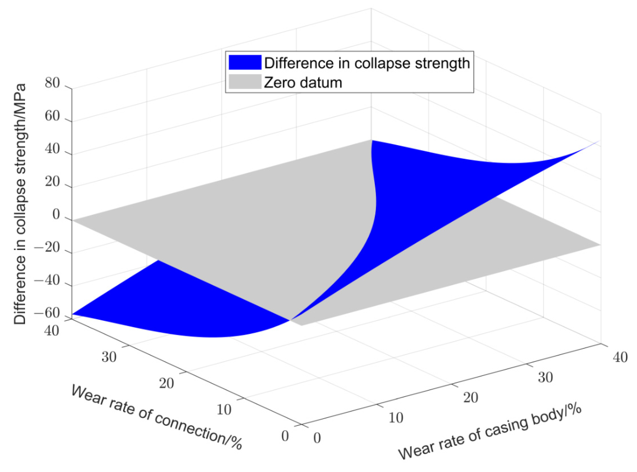
Considering the sealing performance of the connection, the difference of the collapse strength of the connection and casing body with wear rate is shown in
Figure 15. The meaning of this figure is the relative strength relationship between the collapse strength of the connection and the casing body when their wear rate changes, respectively. As shown in the
Figure 15, the grey plane gives a zero datum; above the datum plane is the area where the collapse strength of the casing connection is higher than that of the casing body when the wear rate changes, respectively; below the datum plane is the area where the collapse strength of the casing connection is lower than that of the casing body.
Generally, the wear of the connection is more serious; that is, the wear rate of the connection is greater than that of the casing body. Due to the thicker wall of the connection, only the collapse strength of the casing body is usually considered. However, from the perspective of wellbore integrity, not only the collapse strength under the influence of wear but also the sealing integrity of the casing string should be considered to make the risk assessment of the casing string collapse more practical.
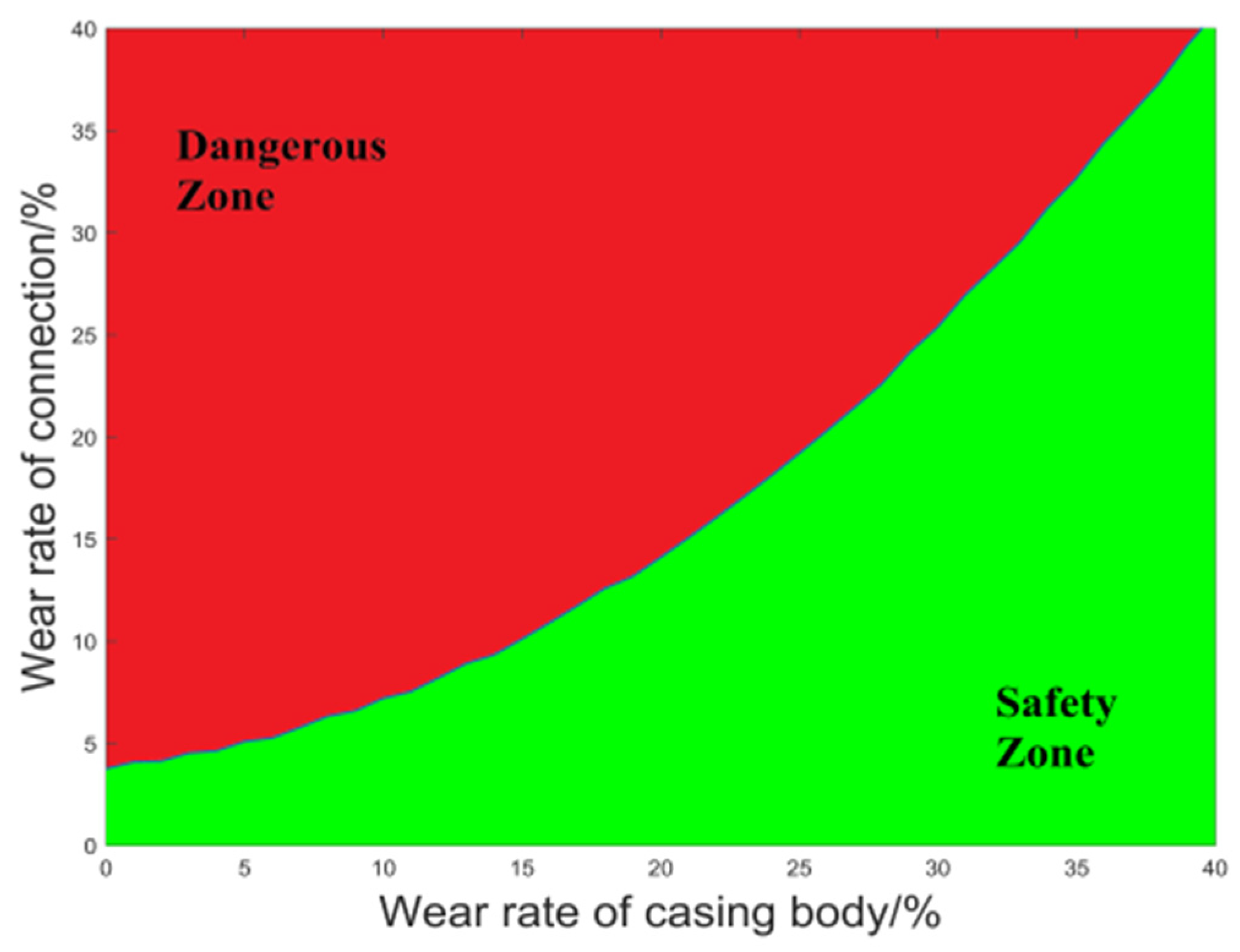
A projection of
Figure 15 on the XY plane can be used to obtain the collapse strength of the casing body and connection based on the sealing integrity, as shown in
Figure 16. Using
to represent the wear rate of the casing body and
to represent the wear rate of the connection, the expression of the red and green areas in
Figure 16 can be obtained by polynomial fitting as follows:
The green area in
Figure 16 shows that the collapse strength of the connection is higher than that of the body under different wear rates. Based on the above considerations, this area is defined as a “safe area”. Since the collapse strength of the connection is greater than that of the body under the corresponding wear rate of the “safety zone”, it is only necessary to evaluate the impact of wear on the collapse strength of the casing body according to Formula (2) to protect the whole casing string from collapse and leakage. The red area in
Figure 16 shows that the collapse strength of the casing connection is lower than that of the body; this area is defined as a “dangerous area”. Under the corresponding wear rate of the “dangerous area”, the impact of wear on the collapse strength of the casing string should be evaluated according to Formula (6) based on the connection.


