2.1. Paired Dataset Training Using CycleGAN
In this study, the training for unpaired day-to-night image translation was conducted using the CycleGAN network, resulting in the creation of a paired dataset. Furthermore, the generated fake night images from the unpaired day-to-night image translation module of CycleGAN were paired with real day images to construct a paired dataset for the creation of a paired night-to-day image translation module using CycleGAN. The proposed method utilizes the CycleGAN structure, which consists of a ResNet generator [
16] and a PatchGAN discriminator [
4]. The structure of CycleGAN is visually depicted in
Figure 1.
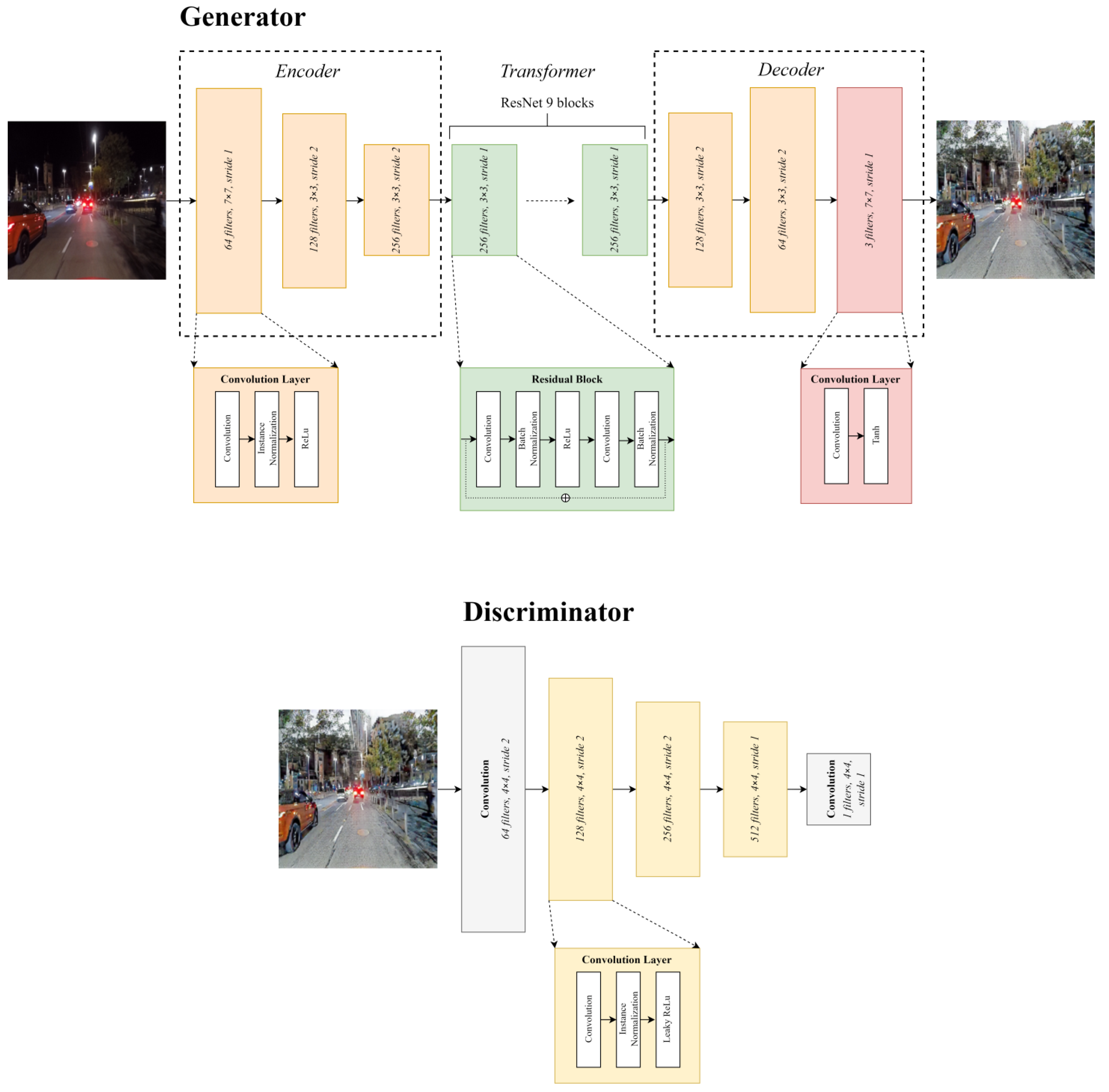
First, CycleGAN comprises two generators and two discriminators because it is an image conversion of two domains. In Pix2Pix, the generator exhibits a U-Net structure; the biggest feature of this structure is the skip connection, which reduces the loss of detail information at a low level. However, because of its limited depth, high-level features such as abstract information cannot be extracted [
17]. Therefore, the generator in CycleGAN uses ResNet. CycleGAN’s ResNet generator possesses a deep network depth and can preserve the detailed parts of data images to a larger extent by utilizing skip connections. As shown in
Figure 1, CycleGAN’s generator consists of three parts: encoder, transformer, and decoder, with the transformer part incorporating residual blocks (ResNet), as depicted in
Figure 1.
The discriminator in CycleGAN follows a similar approach to PatchGAN, which is similar still to Pix2Pix. The patch size of PatchGAN is determined by the receptive field size, which is determined by the number of convolution layers in the discriminator. The final output of PatchGAN can be obtained by either averaging all values in the last feature map or using a one-dimensional scalar value as the output throughout the layers. In CycleGAN’s PatchGAN discriminator, a one-dimensional scalar value is used as the final output to determine the authenticity of an image. This approach is computationally efficient and incurs low cost. The patch size in CycleGAN is typically around 70 × 70, enabling the application of the patch-level discriminator structure to images of various sizes with fewer parameters. An activation function is applied in the last layer of the discriminator to classify the results. CycleGAN does not employ a separate sigmoid function or activation function for classification, but rather utilizes mean square error loss, borrowed from LSGAN [
18], to determine the authenticity of the image. The structure of CycleGAN ensures the effective determination and updating of the loss value.
The proposed method involves the use of two CycleGANs. The first CycleGAN training focuses on unpaired learning for day-to-night image translation, which serves as a data augmentation task to compensate for the limited number of paired day and night images. Subsequently, the second CycleGAN training is performed for night-to-day image translation and detail enhancement. In the first CycleGAN module, the night images, which serve as paired images to the day images, are generated using base night images that have been blurred with a bilateral filter. Real day images corresponding to the night images are processed with a single-scale luminance adaptation transform (SLAT) [
19] to construct the training dataset for the second CycleGAN training.
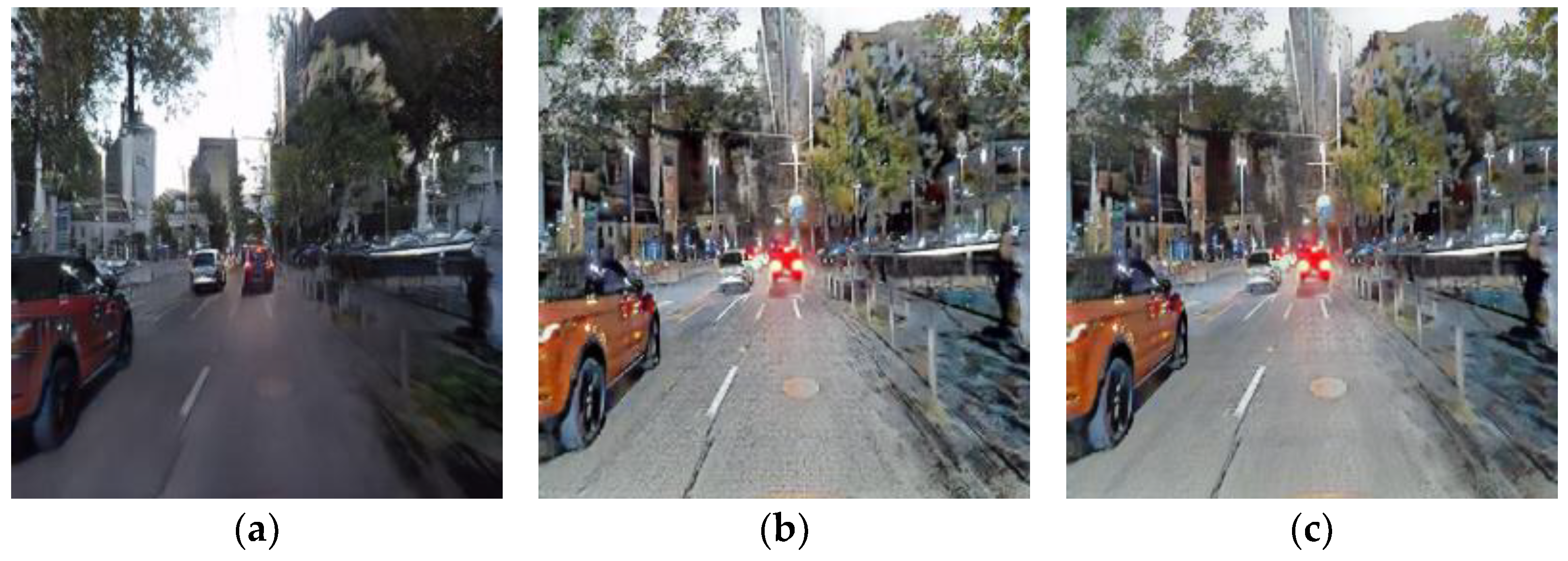
Although CycleGAN is designed for unpaired image-to-image translation, the night-to-day image translation is performed using paired learning. This is because the results obtained from paired learning with CycleGAN outperform those obtained from paired learning with Pix2Pix.
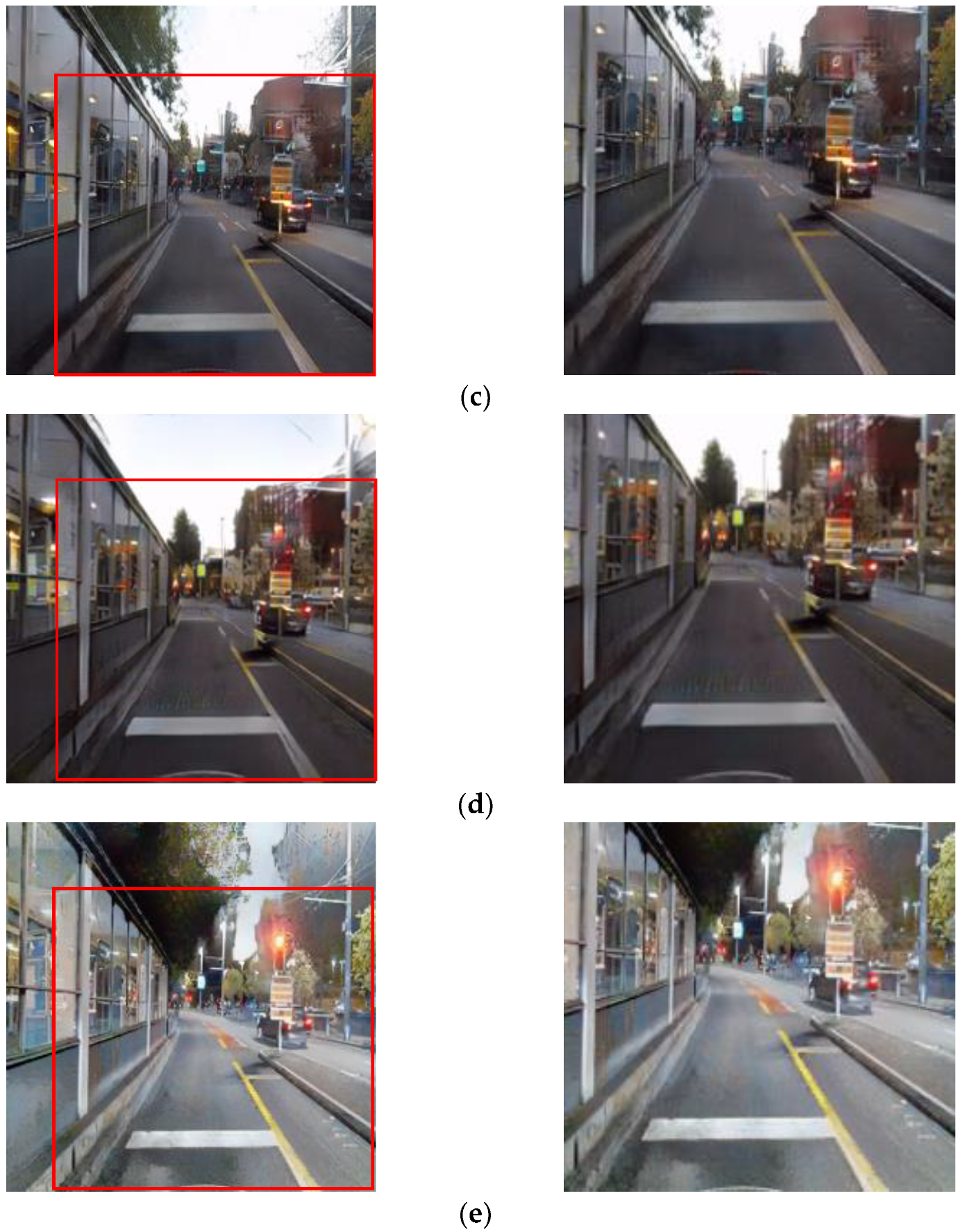
Figure 2 illustrates this comparison, where training with the same paired dataset resulted in a blurry image when using Pix2Pix (
Figure 2b), whereas the image generated with the CycleGAN pair module (
Figure 2c) is slightly clearer. The improved clarity in the resulting image of CycleGAN, compared with Pix2Pix, is attributed to CycleGAN’s ability to address the mode collapse problem through cycle consistency loss and its ability to preserve color using identity loss.
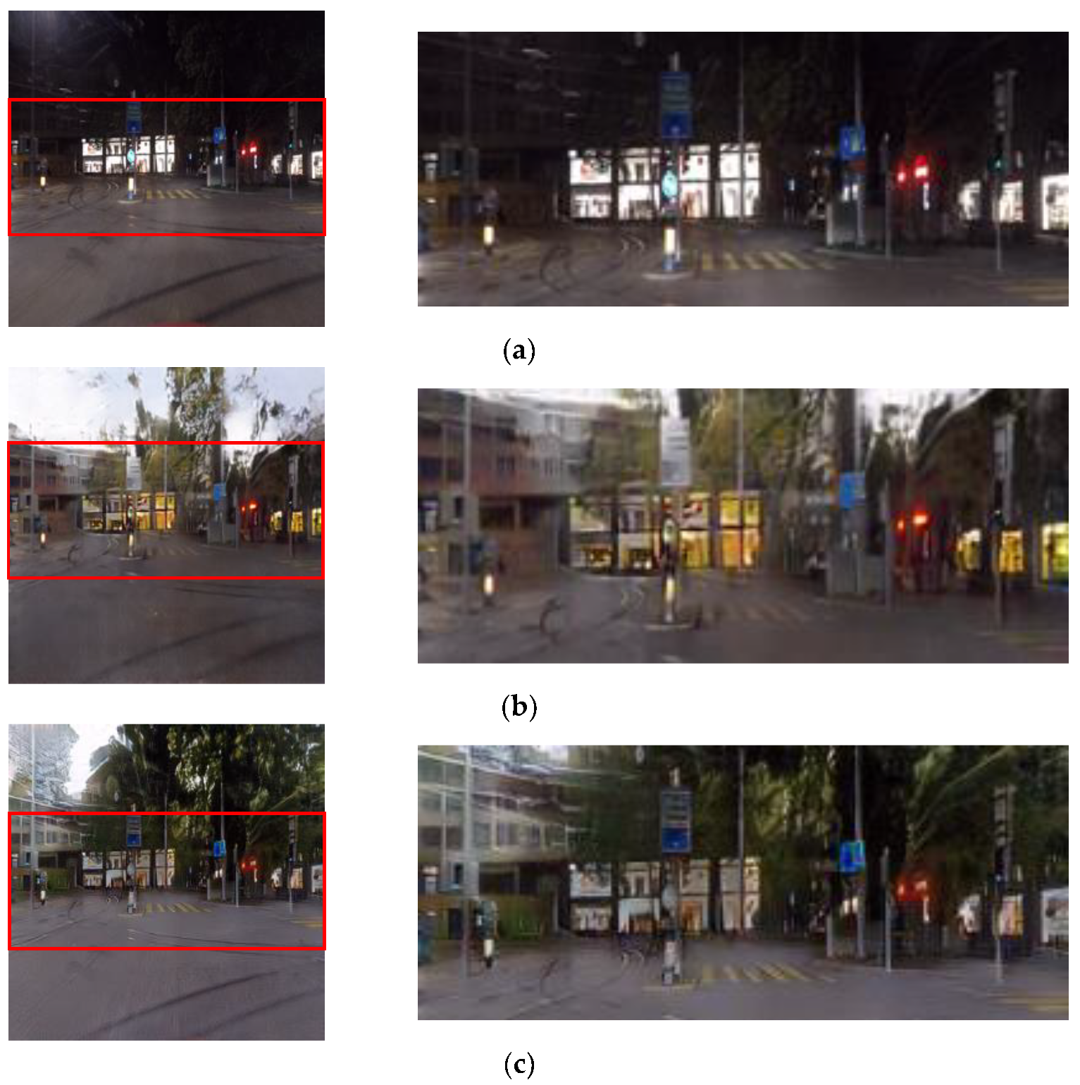
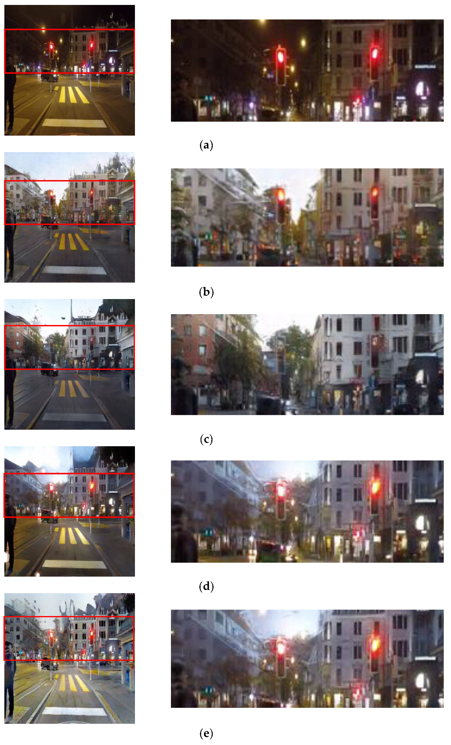
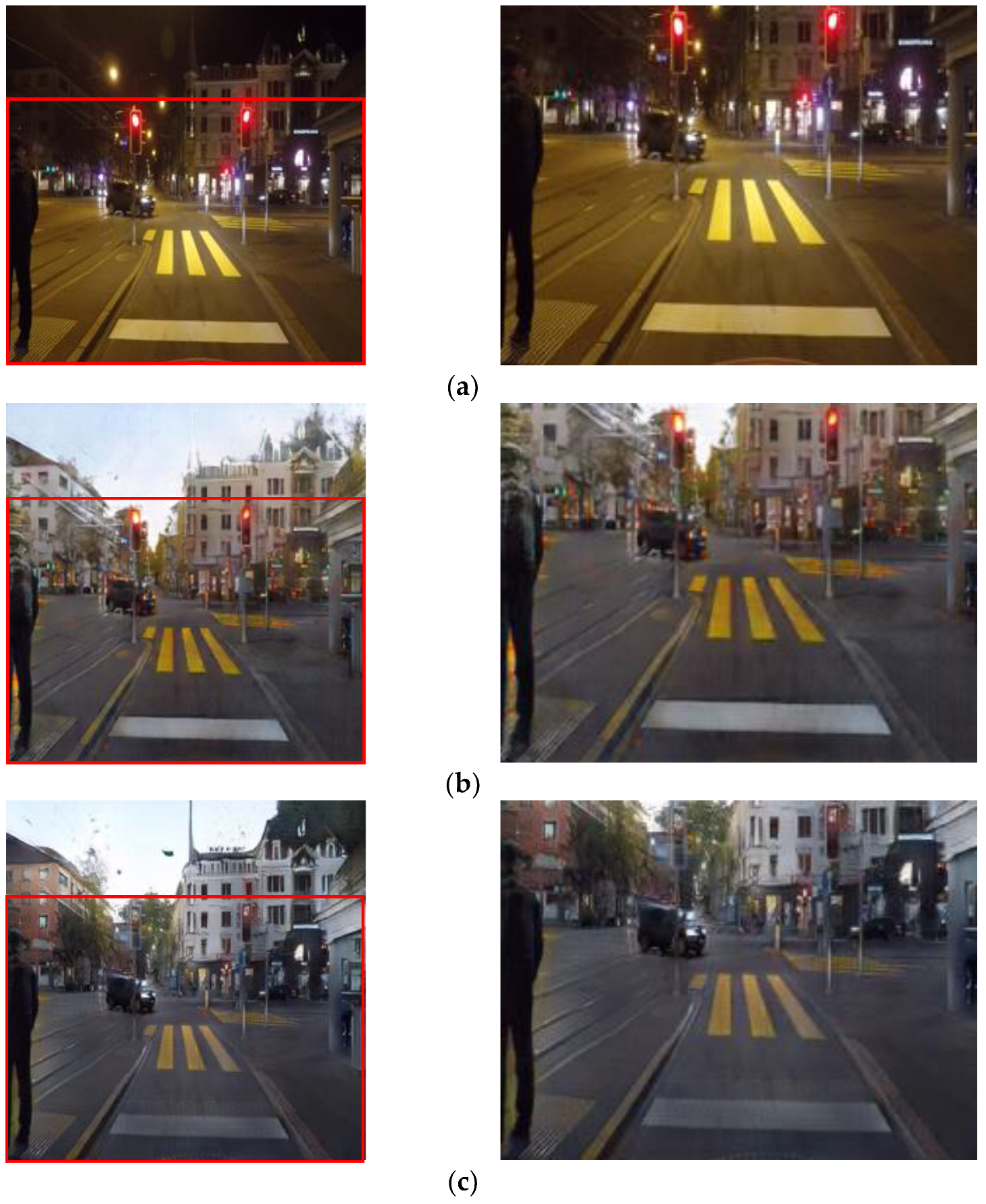
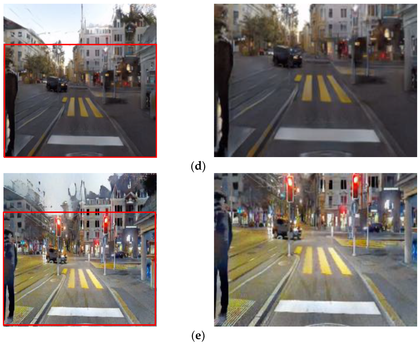
Another reason for using pair learning in CycleGAN is that unpaired learning can lead to distortions in traffic light colors.
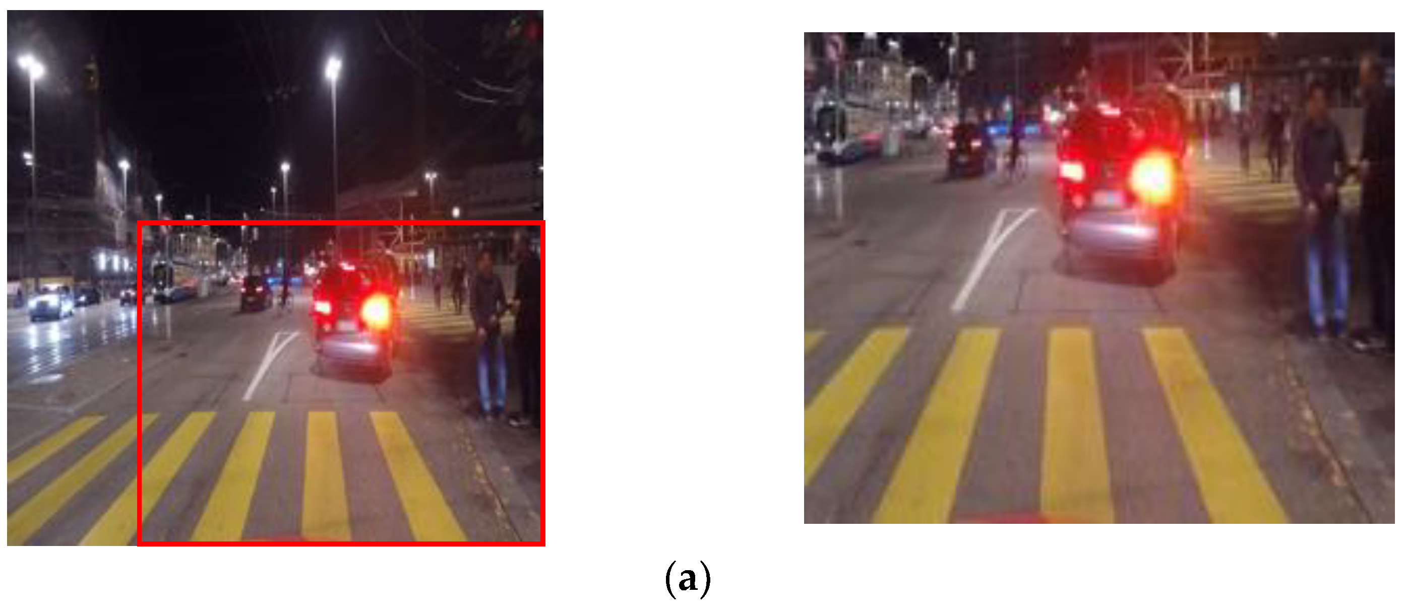
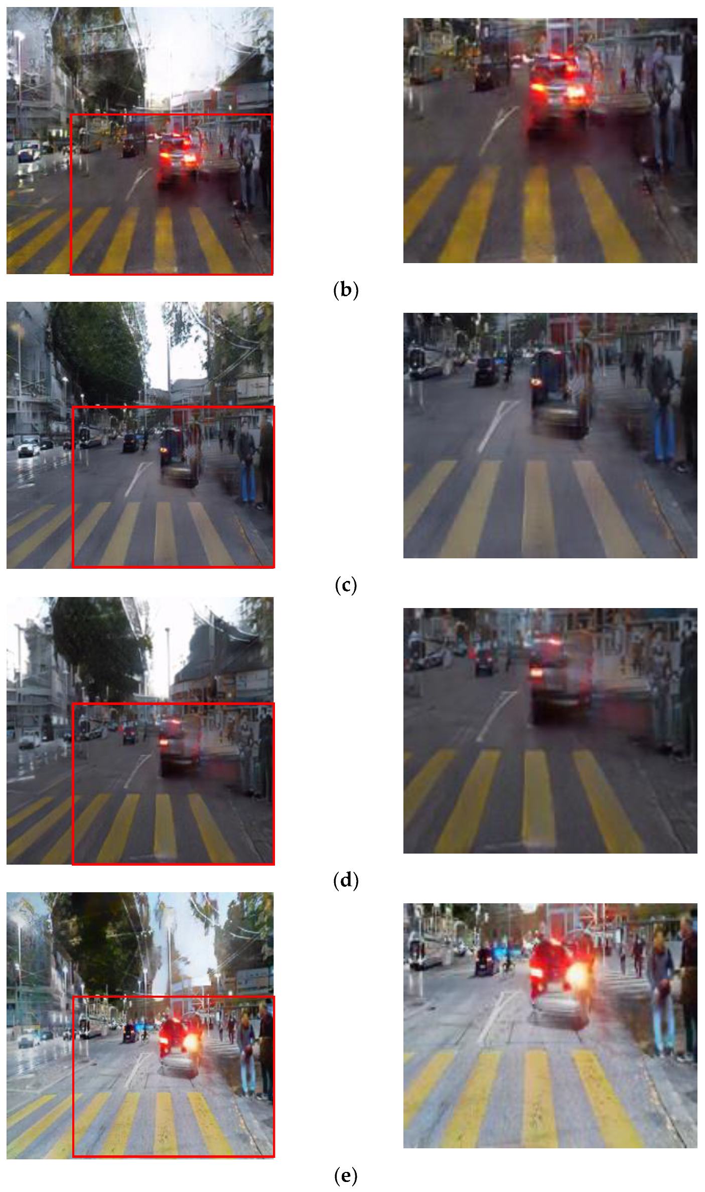
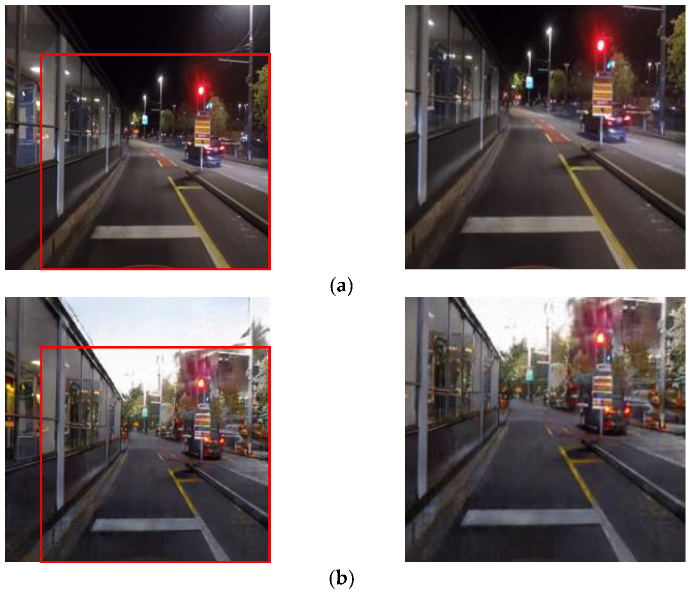
Figure 3 presents a comparison of four methods: Pix2Pix, unpaired CycleGAN, paired CycleGAN, and the proposed method. Unpaired CycleGAN suffers from information deficiency compared with paired learning, which can result in color distortions of traffic lights and even the disappearance of signs.
Figure 3c displays the result images obtained from training with unpaired CycleGAN. Upon closer examination of the cropped image, it is evident that the traffic light color is faint and the representation of the traffic light itself is inadequate. Moreover, in the remaining paired training images, such as Pix2Pix, paired CycleGAN, and the proposed method module, there is relatively better preservation of traffic light color. Therefore, it can be observed that the representation of traffic lights in the result images from paired training methods is superior to that of the unpaired CycleGAN module. Specifically, the result images from the proposed method module not only enhance the details of objects but also depict signage more clearly, as can be seen in the images.
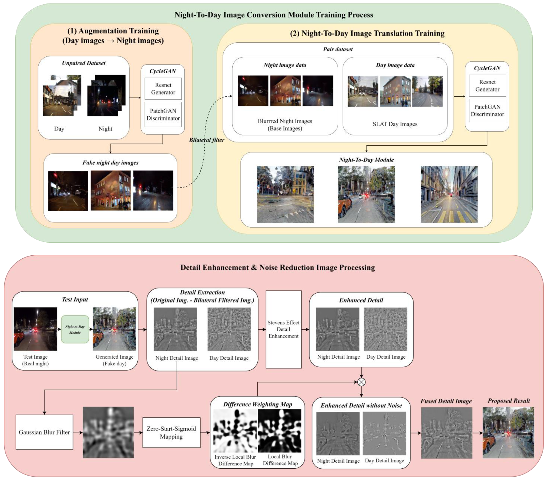
The proposed training method in this study aims to preserve the original colors and objects of the input images while enhancing object details. To achieve this, paired CycleGAN training was utilized. The block diagram in
Figure 4 illustrates the proposed method, which involves unpaired CycleGAN training to generate fake nighttime images. These fake night images were then paired with daytime images to create a day–night paired dataset. In the next step of CycleGAN pair training, the fake night images were blurred using a bilateral filter. The original fake night images and the blurred fake night images were subtracted from each other, resulting in base night images, which represent the differences between the images.
To perform both day conversion training and detail training simultaneously, SLAT processing was applied to the real daytime image corresponding to the base fake night image to construct a paired dataset. SLAT processing is an image processing technique that preserves detail areas while improving local contrast. It involves two main processes: local tone mapping of luminance channels and chrominance compensation of chrominance channels. However, in this study, the chrominance channel compensation method was omitted to simplify the SLAT processing. Instead, the RGB channels of the real daytime image were separated, and the luminance components of each channel were used for local tone mapping.
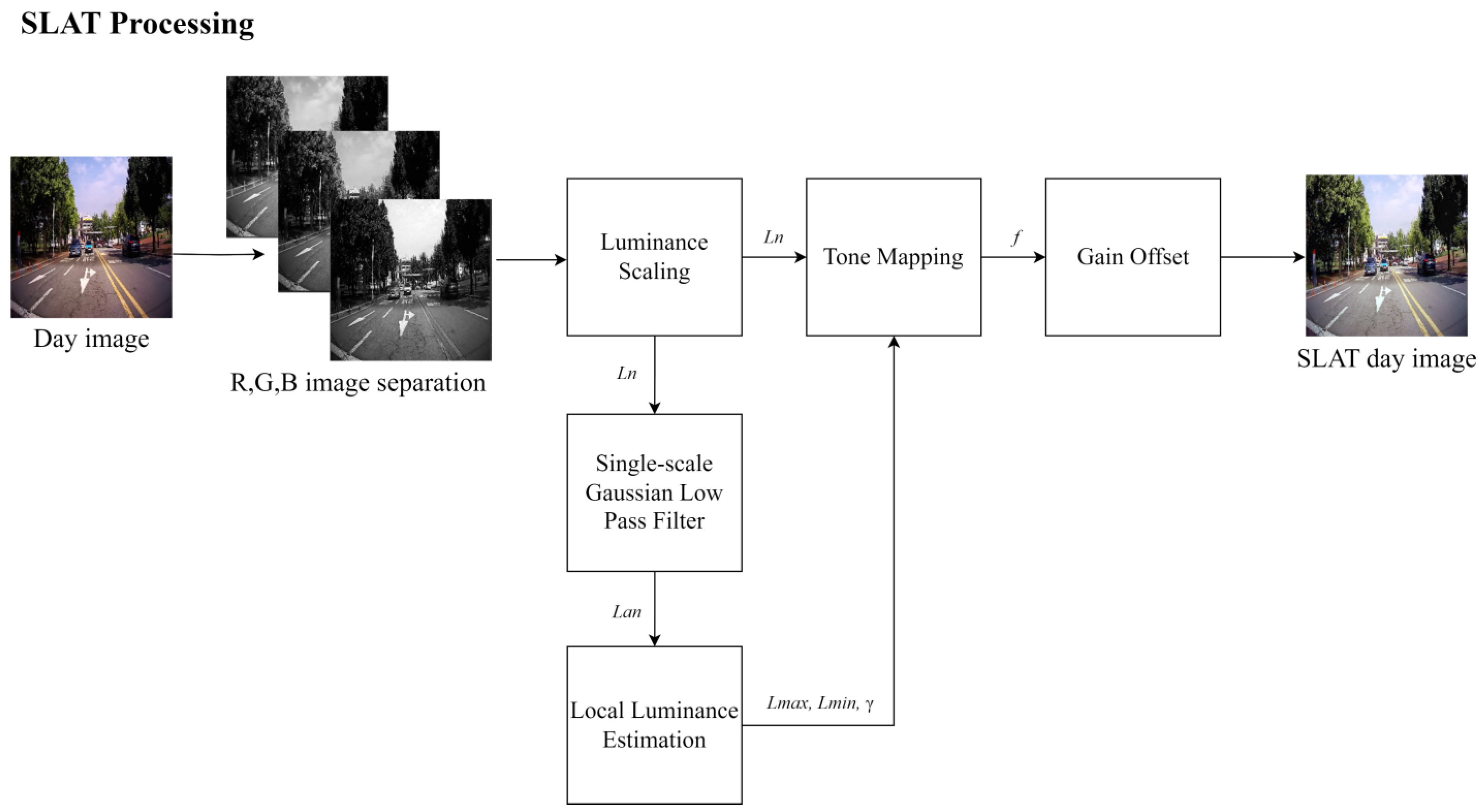
Figure 5 illustrates the process of SLAT processing. Overall, the proposed training method combines unpaired CycleGAN training, bilateral filtering, and SLAT processing to create a paired dataset and enhance object details while preserving the original colors and objects of the input images.
SLAT adjusts the visually compensated gamma value according to the local adaptive luminance level. The luminance level is divided into minimum and maximum luminance levels. To set the maximum value of the luminance channel to 100, luminance scaling normalization is performed because local luminance estimation is designed according to an adaptation luminance of 100
as the surrounding luminance. Next, a single-scale Gaussian low pass filter is applied to each RGB luminance scaled image to create an adaptation luminance image (
) that is essentially an image of the surrounding area. Luminance scaling normalization and normalized adaptation luminance are calculated using Equations (1) and (2).
where
is a normalized luminance scaling input image, and
is the input luminance image. The RGB image is the luminance image in this study. Therefore, the R channel
, G channel
, and B channel
are generated.
where
is the normalized adaptation luminance calculated by a single-scale Gaussian low pass filter, and
is a Gaussian low pass filter. This
surrounding image is also generated by the RGB channel.
Next, local luminance estimation is performed to calculate the
,
, and
of each RGB channel. Here, the γ value is the visual gamma value that affects SLAT based on the Bartelson–Breneman brightness function [
10]. Values can be obtained using Equations (3)–(5):
where
is the minimum luminance level,
is the maximum luminance level, and
is the visual gamma value.
Applying the visual gamma value to the Bartelson–Breneman brightness function curve and applying it to the calculated luminance image values thus far yields the SLAT image, as expressed in Equation (6):
where
is the Bartelson–Breneman brightness function curve with the visual gamma value,
is an image processed by a single luminance adaptation transform,
is a normalized luminance scaling input image,
is the minimum luminance level,
is the maximum luminance level, and
is the visual gamma value. The SLAT result image enhances the local contrast and desaturates the bright area.
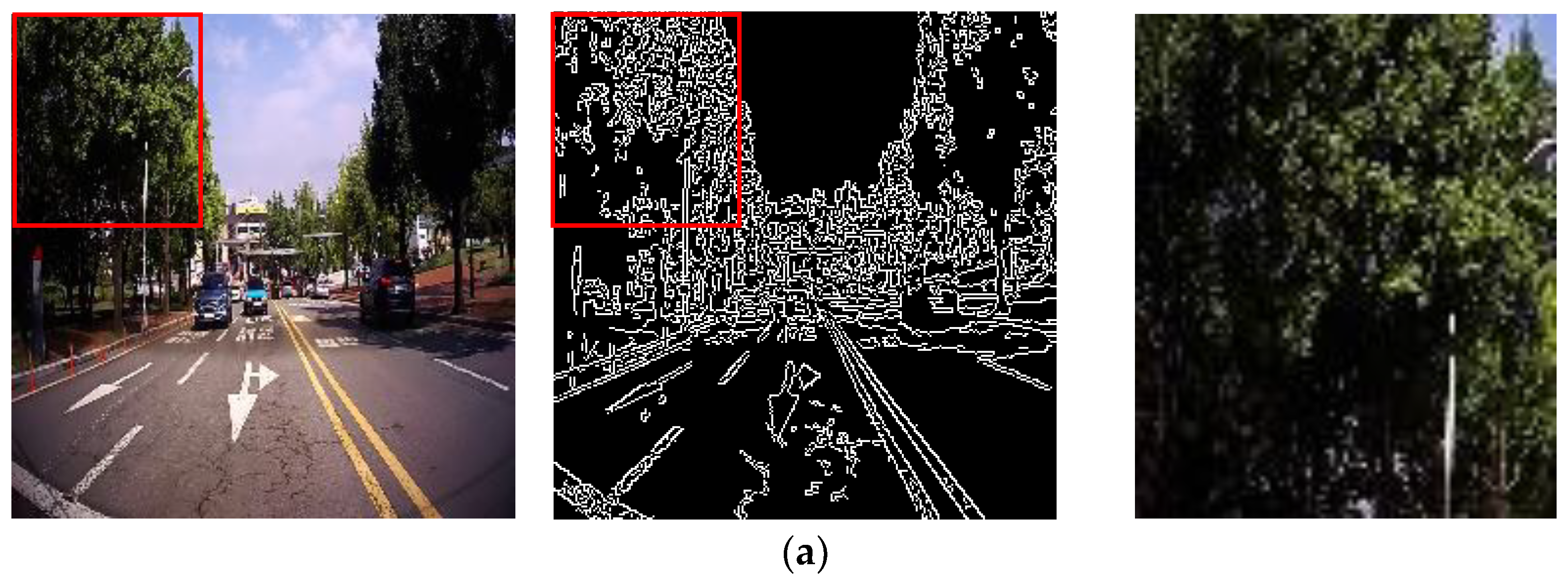
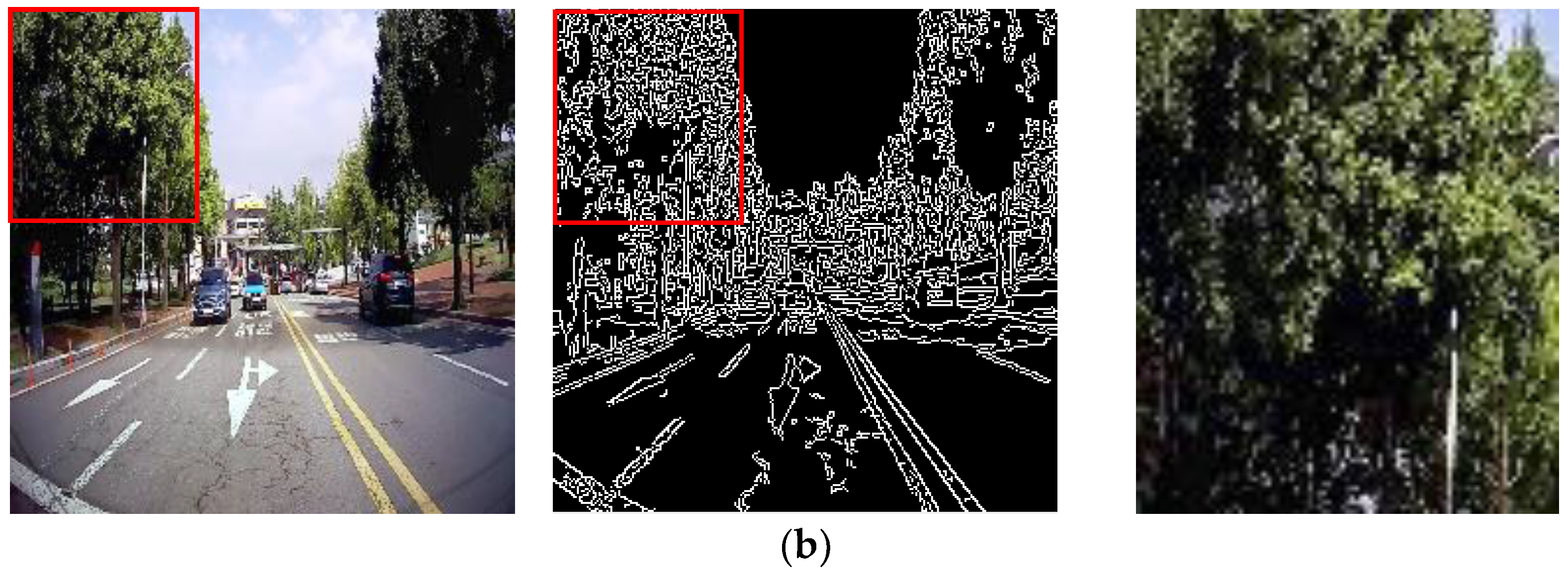
In
Figure 6, a comparison between the SLAT-processed image and the original image has been conducted to examine the presence of artifacts such as ringing effects, where erroneous boundaries are formed in the surrounding regions, resulting in a loss of local contrast and a decrease in image sharpness. When comparing the SLAT-processed image with the Canny edge image, it was observed that the SLAT-processed image exhibited minimal formation of erroneous boundaries, and there were areas where the local contrast increased, leading to better representation of details compared to the original image. Therefore, utilizing SLAT processing on low-light images before training could potentially assist in enhancing the representation of object areas.
The real daytime images, after being processed with SLAT, and the fake nighttime base images generated through unpaired CycleGAN training were utilized as paired images for training in the paired CycleGAN. The resulting paired CycleGAN (base-detail model) effectively enhances the local contrast and restores fine details in the daytime image, leading to improved object identification.
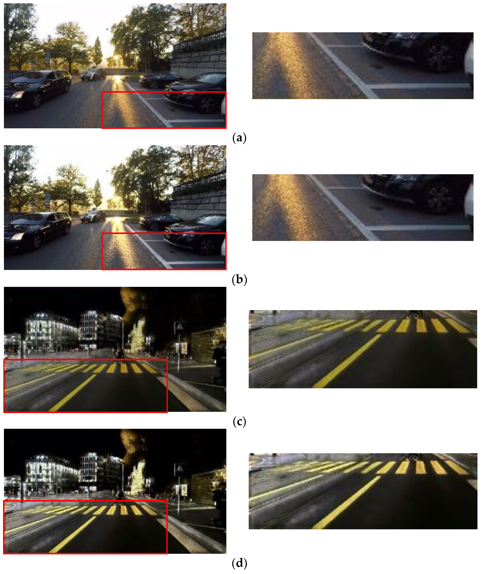
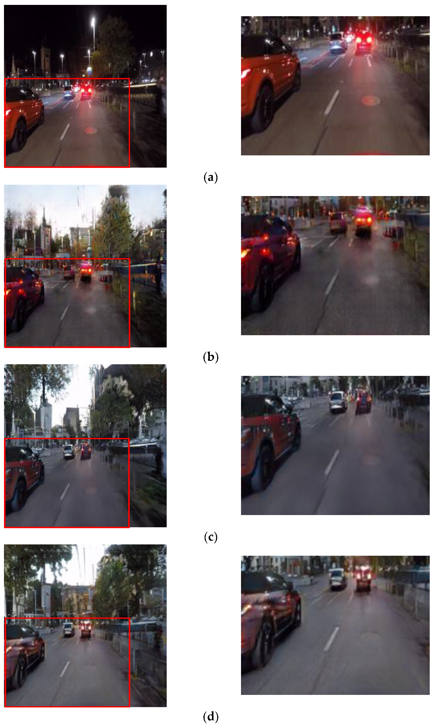
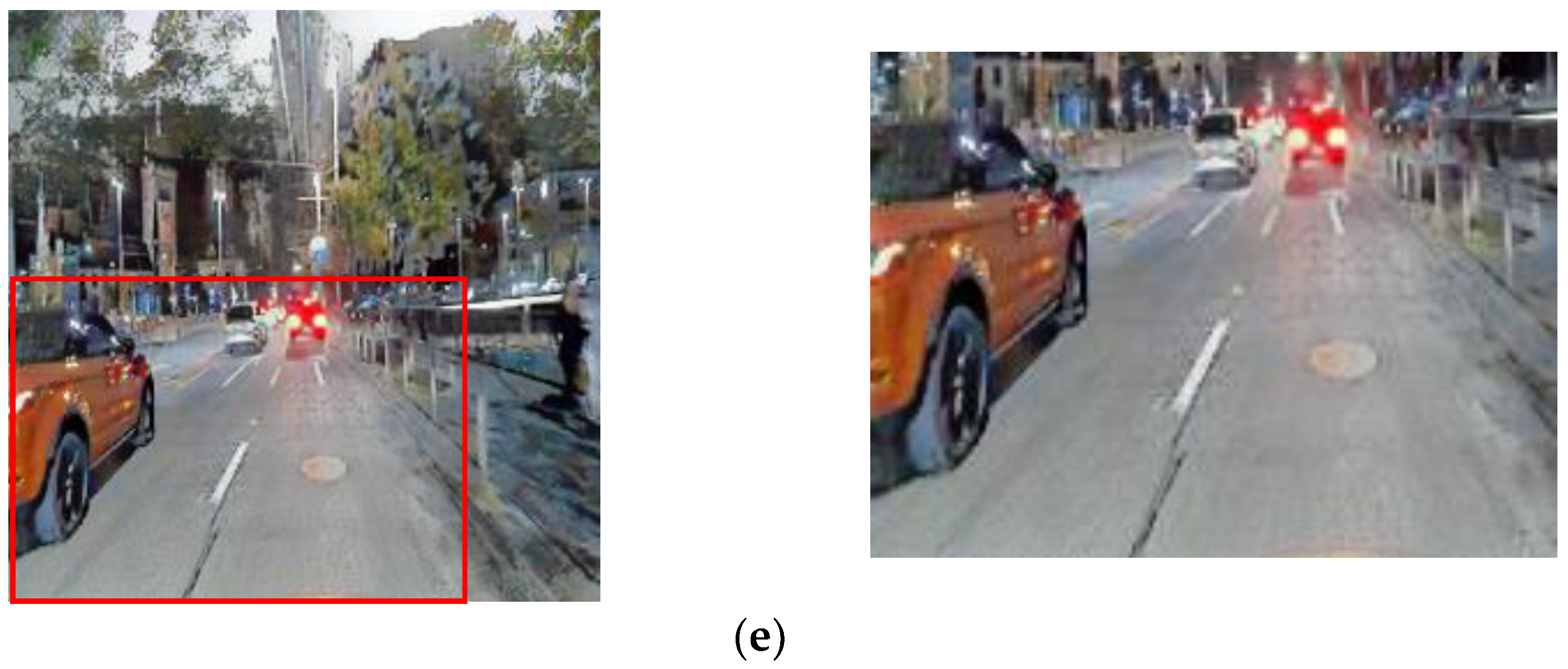
Figure 7 presents a comparison between the result images of unpaired CycleGAN and the base-detail model. The base-detail model effectively describes objects by enhancing their details, but it also introduces noise. Excessive enhancement of details can lead to noticeable noise in the resulting images. Therefore, it is crucial to employ image processing techniques that preserve details while reducing noise.
2.2. Detail Enhancement and Noise Reduction
To address the increased noise in the resulting image from the base-detail model, image processing techniques are employed to reduce noise while enhancing detail information. As illustrated in
Figure 4, the proposed approach utilizes the Stevens effect and a local blur map to achieve this. Initially, the detail information is extracted from both the real nighttime images and the resulting daytime images from the base-detail model by obtaining the difference image. This difference image contains the detailed information of both the night and day images, obtained by subtracting the original image from the image blurred with a bilateral filter. Subsequently, the Stevens effect is applied to each detail image of the day and the night, enhancing the sharpness of the detail components while considering visual characteristics. The mathematical expressions for the Stevens effect are defined in Equations (7)–(9). These equations provide the framework for enhancing the details and improving the visual quality of the images.
where
is an image with bilateral filter blur,
is the adjustment factor, and
is 20% of the adaptation luminance.
where
is a factor of various luminance-dependent appearance effects that is used to calculate the detail enhancement of the Stevens effect.
where
is a sharper detail image based on the application of the Stevens effect to the detail image, and
refers to the detail extraction image. The Stevens effect is utilized to refine the details by considering the anticipated modifications in luminance levels. Specifically, as the luminance level rises, there is an augmentation in local perceptual contrast, resulting in the visual enhancement of details. The alteration in detail, enhanced through the application of the Stevens effect, is illustrated in
Figure 8. Notably, the image with the Stevens effect applied appears noticeably clearer, reflecting the effectiveness of this technique in enhancing visual clarity.
To mitigate noise in the resulting image from the base-detail model, the proposed method employs a local blur weight map to reduce noise while preserving essential details. The generation of the local blur weight map relies on the differential image of the night image. This choice is motivated by the fact that regions with pixel values close to zero in the difference image indicate the absence of detail information, while nonzero pixel values correspond to regions with detail information. Thus, the difference image serves as a criterion for selecting regions where noise can be locally reduced while preserving detail. The difference image of the nighttime image is essentially the same as the nighttime detail image mentioned earlier.
In order to use the difference image as a blur map, it undergoes blurring with a Gaussian blur filter to create a visually blurry representation. To render the blurred difference image suitable as a weight map, the values of the difference image are stretched. It is important to avoid extreme separations in the local blur weight map, as they can introduce unnatural representation of image details and image distortion artifacts. To address this, the values of the local blur weight map are mapped to a sigmoid-type graph, which reduces the occurrence of such unnatural phenomena. However, since the standard sigmoid function starts within a range smaller than zero, a modified sigmoid function is employed in this context. Specifically, the sigmoid function is set to start from zero. The resulting difference blur map, generated using this modified sigmoid function formula, is represented by Equation (10).
where
is the local blur difference weight map and
is an input image of the Gaussian blurred difference image. The application of the sigmoid function to the local blur weight map and its subsequent use for blurring is aimed at achieving a more natural appearance in the resulting image.
In essence, a locally applicable local blur weight map is necessary to reduce noise and preserve details. This weight map can be generated from the difference image of the nighttime image. However, if the weight map follows a linear step-like form, it can lead to image distortion or unnatural artifacts. By mapping the weight map values to a sigmoid function, a non-linear local blur weight map can be created, mitigating unnatural artifacts in the image while locally attenuating noise.
To enhance details in both the nighttime detail image and the daytime detail image, the Stevens effect is applied. Consequently, two local blur weight maps are required: one corresponding to the nighttime detail image and the other to the daytime detail image. The local blur weight map for the nighttime detail image can be obtained using the weight map mentioned earlier. However, for the daytime detail image, the local blur weight map needs to be in an inverse form. This is because regions with pixel values close to zero in the difference image of the nighttime image potentially indicate the presence of objects in the corresponding regions of the daytime image. Thus, it is necessary to preserve these regions in the daytime image. By utilizing the inverse local blur weight map, it becomes possible to incorporate the daytime image’s detail information in areas where the nighttime image lacks detail, thus preserving details throughout the entire image. This relationship is expressed mathematically as shown in Equation (11).
where
is a synthesized detail image processed based on the Stevens effect.
is an image representing a local blur weight map using a difference image of a night image as shown in Equation (10), and (
) is an inverse local blur map image.
Finally, as shown in Equation (12), the proposed result image is generated by adding the base image of the generated day image and the enhanced detail image.
where
is a result of the proposed method,
is an enhanced detail image based on the Stevens effect as shown in Equation (11), and
is an image of the base-detail model’s result without detailed information.
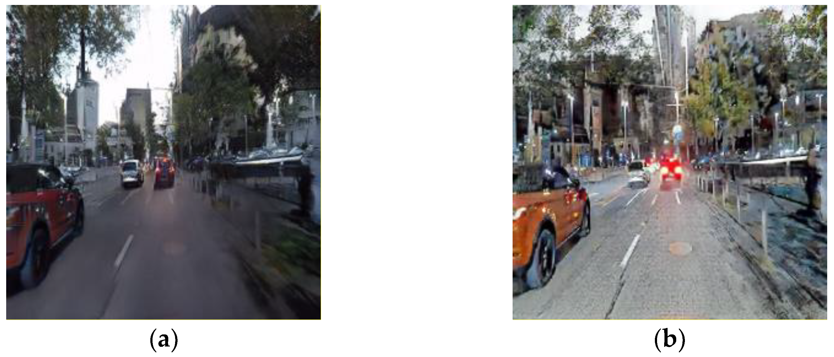
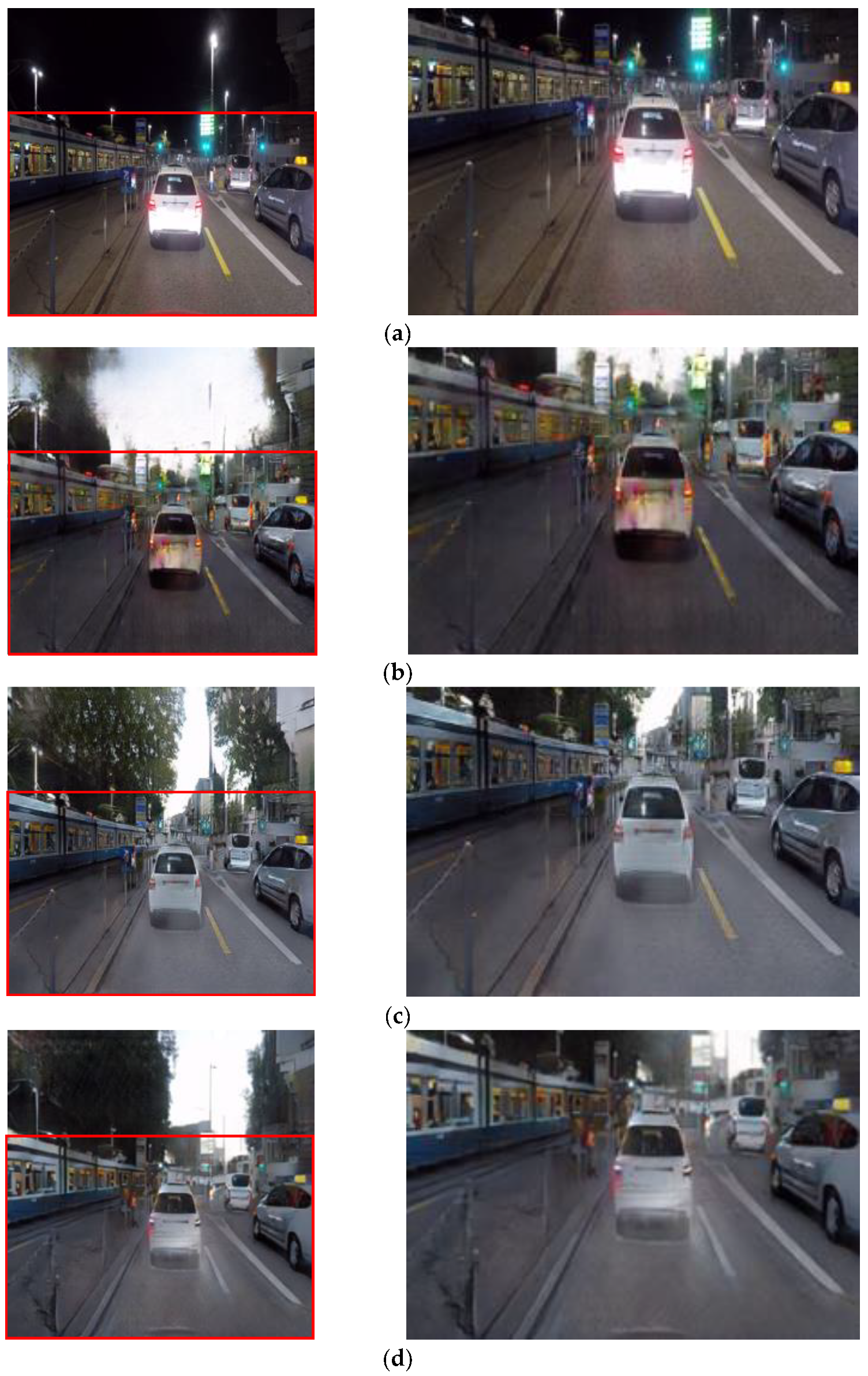
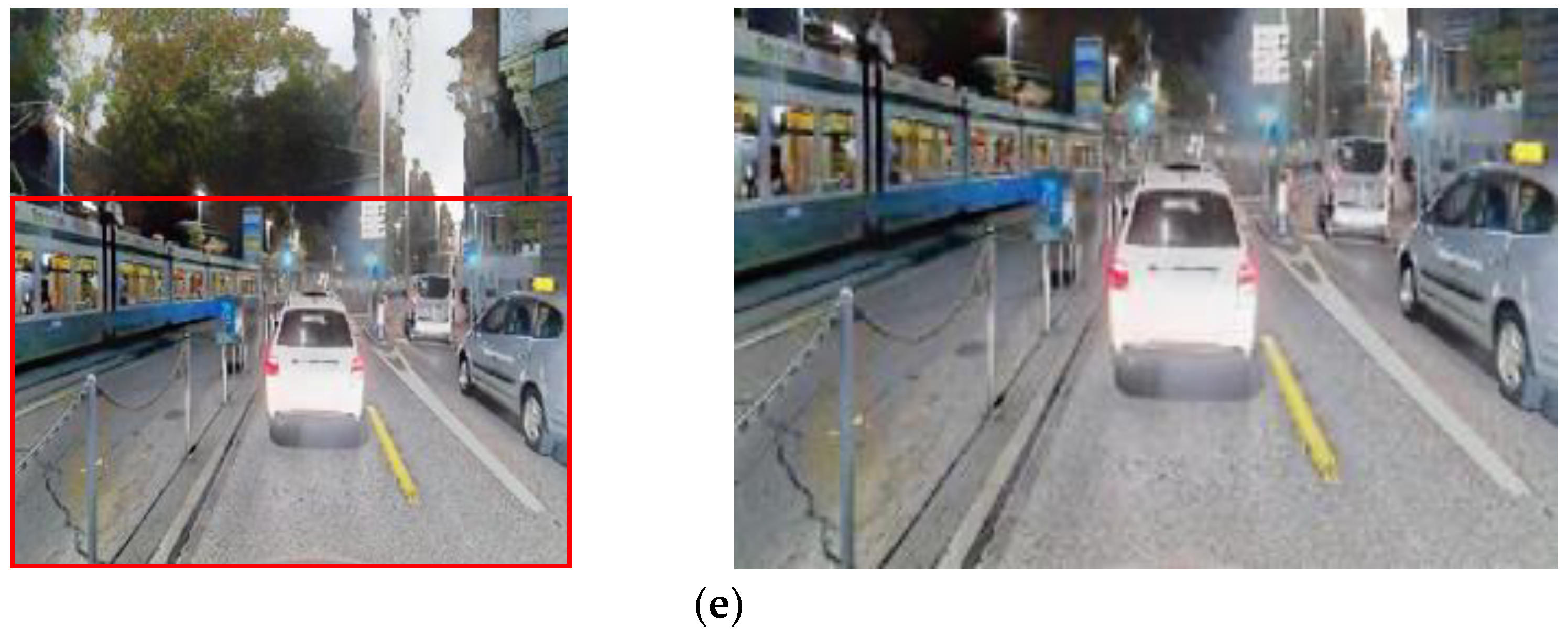
In conclusion, the proposed method employs a paired CycleGAN module to convert nighttime images into daytime images. The fake daytime images generated in this module undergo detail enhancement using the Stevens effect and a local blur weight map, which takes into account visual characteristics. This enhancement process aims to improve the visual detail information while reducing noise. As a result, the final converted daytime image allows for better recognition of objects even in low-light conditions. The Night2Day image translation results are presented in
Figure 9. It is evident from
Figure 8 that the Night2Day image exhibits improved and sharper details compared with the existing CycleGAN result image. Moreover, it can be observed that the noise is reduced and the detail areas are preserved in comparison to the image generated by the base-detail module.


