1. Introduction
Compliance checking is the guarantee of engineering quality. Traditional specification checking relies on a manual review of design models, which is not only inefficient but also prone to errors [
1]. With the development of information technology, more and more researchers pay attention to automated compliance checking, and work in different fields has also made progress [
2]. The first task is to extract or represent the rules of the specification in the research of automated compliance checking, building codes, or other statutory documents written in natural language so that they can be understood by humans [
3]. The main difficulty at present is how to convert the text, tables, and other forms of content in the specification into logical expressions that can be understood by computers [
4]. In order to achieve complete automation, the textual information, as well as tabular information, in specification provisions is completely processed through NLP (Natural Language Processing) technology [
5,
6]. However, written language is often too lenient, which makes it impossible to process it automatically and accurately. There are programming languages to realize the representation of rules [
7,
8]. This practice of ‘hardcoding’ design criteria into the design program is a major obstacle to the development of computer-aided engineering because it does not enable designers to view and understand the presentations of design standards on which the computations are based [
9]. Semantic Web technology can represent heterogeneous information from different sources through formalized, standardized knowledge, from which explicit information can be obtained [
10]. Semantic Web technology is used for compliance checking and is increasingly favored by researchers [
11]. Ontology as a part of the Semantic Web is also used to represent specification information, such as construction planning verification [
12] and construction safety specifications [
13]. There are other rule representation methods, such as the representation of building envelope code based on the decision table [
1]. The specifications applied to these rule representation models or methods are usually numerical judgment or Boolean judgment, such as judging the size of components. Therefore, the comparators used in these rule representation models to judge compliance are usually numeric comparators (>, <, =) [
14] and Boolean comparators (yes, no). However, the constraints of some specifications are the relationship between objects. For example, the equipment room must be equipped with a ventilation system, which specifies the relationship between the ventilation system and the equipment room. There are more general spatial relationship constraints, such as “The canopy must be installed above the entrance and exit. “ The numeric and Boolean comparators are no longer suitable for the representation of this type of specification.
When the appropriate rule representation model is established, it needs to correspond to the building information data in order to execute the rules and obtain the results. The current popular data standard is the IFC (Industry Foundation Classes) standard and its ontology form ifcOWL, which is used in some compliance checking research [
15,
16]. The checking results are obtained by retrieving data or rule reasoning. However, there are studies pointing out that the IFC standard is not sufficient for data integrity of compliance checking [
17]—semantic enrichment or extension is required. The integrity check is to check whether the model has enough information in the specific scenario [
18]. In compliance checking, the information integrity of the constrained object or whether the constrained object meets the check conditions should be determined first. For example, the equipment room must be equipped with a smoke alarm. When this specification is checked, first, it is necessary to find the room that is the equipment room. In this process, it may be due to the negligence of the modeler or the model error that the equipment room is not found. The result can show that the model does not conform to this specification, but the actual result should be that the object does not meet the checking conditions or the information is incomplete and the judgment on the checking results has not been executed. The integrity of building information is an issue involving the expression format of building information and the delivery of building information. Building information delivery is about the demand for building information at different stages of the engineering design process. MVD (Model view definition) is defined as the delivery form of building information in IFC, or as the building information model data standard. Obviously, this part of the work requires a large number of professionals to define the required information [
19]. Due to the lack of definition of demand information in compliance checking, priority should be given to judging whether the constraint object of the specification meets the checking conditions in the compliance checking process.
Therefore, this paper proposes a new code representation model, which consists of constraint subject, constraint mode, constraint content, constraint value, and constraint items. The constraint mode includes numerical comparison and relationship constraints. Relationship constraints can represent not only general spatial relationship constraints but also domain relationship constraints. The determination of the constraint subject can also distinguish between the checking conditions and checking requirements defined in the specification, which can provide more semantics for the checking results. Then, the mapping between concepts of building information ontology and code knowledge concepts is established in order to automatically generate reasoning rules. Finally, compliance checking in a metro model was used to validate the code representation model. The paper is organized as follows:
Section 2 reviews recent literature on compliance-checking methods.
Section 3 proposes a code representation model.
Section 4 elaborates on the checking methods for different spatial relationship constraints.
Section 5 presents the extraction of specification knowledge.
Section 6 realizes compliance checking by establishing the mapping between code knowledge and ifcOWL.
Section 7 shows the feasibility of the proposed method using an example.
Section 8 concludes the study and elaborates on future work.
2. Related Work
Compliance checking has always been a hot issue in the field of building information. More and more researchers have carried out compliance-checking studies in different fields. The compliance checking process approved by almost all researchers was proposed by Eastman [
20] in four steps: rule interpretation, model construction, rule execution, and checking report.
With the development of compliance checking research, more advanced and intelligent technologies, such as artificial intelligence and Semantic Web technology, are used to improve the automation of compliance checking. The traditional four steps are divided into five steps in the process of automatic compliance checking [
21].
Extract and represent rule content
Rule language represents rule content.
Transform model data into knowledge representation.
Implement the rules.
Obtain results or reason new knowledge.
This section reviews the compliance check steps according to these five parts, in which “implement the rules” and “obtain the results” are combined.
2.1. Extract and Represent Rule Content
The goal of the first step is to represent the rule information in the specifications, which is a challenge for compliance checking. Both traditional and new processes are given significant attention to rule representation.
Some researchers try automatic or semi-automatic methods to extract rule information from textual provisions, including machine learning [
22] and natural language processing method [
23]. However, building code is a highly specialized domain that needs to rely on the professional knowledge of domain experts [
24]. Most studies still focus on manual processing.
In terms of rule representation, rule representation methods that can be quickly understood by experts and solve the problem of rule language generation are recommended, such as visual language. The KBIM Visual Language proposed by Hayan [
25] represents rules, which is helpful for novice programmers and rule reviewers. This visual language can also be translated into computer-readable code. There are also researchers who create a rule interface that allows users to edit manually. Marco [
26] proposed to visualize the specification rules in the way of BPMN (business process model and notation) and DMN (decision model and notation). BPMN represents the specification information through the coded process. Fan [
27] developed a user-oriented interface that enables users to establish rules visually, and the specified rules are more like a mathematical calculation process. In addition, some researchers propose or draw on existing logic models to describe rules. Zhang [
28] represents rules through FOL (first-order logic) because FOL is considered to be able to express English sentences, which makes FOL suitable for representing specification information. Because of different forms of specification expression and even different grammatical structures, different methods have their own characteristics. However, the compliance judgment is mainly based on numerical value or Boolean judgment, and the relationship judgment of objects is rarely considered. Although the judgment of some relationships can be transformed into the judgment of numerical or Boolean relationships by using domain knowledge, Sydora [
29] represents the spatial relationship as functions in the checking process, and the values of the relationship between object instances generate a Cartesian table to determine compliance. This method relies on the inspector’s understanding of the specification to explain spatial relationships. On the other hand, these studies mainly focus on the expression form of constraint content in the specifications. The integrity of constraint objects is ignored in the checking process. Hjelseth [
30] marks the checking requirements and applicability of constrained objects through the RASE model. The RASE model can represent some checking conditions of constrained objects, but the objectives of checking requirements and checking conditions are inconsistent. The additional associations and logical relationships need to be added as the expression of the constraint content with restrictions cannot be expressed.
2.2. Rule Language Represents Rule Content
The second step is to transform the rule information extracted from the specifications into a rule language that can carry out reasoning. There is Prolog rule language [
31] in Drools rule engine, and Zhang [
32] uses the Prolog rule language to implement compliance checking. In addition, there are rule languages in the Semantic Web field, such as SWRL (Semantic Web Rule Language) [
33], N3Logic [
34], and Pauwels [
35], which uses N3Logic to represent rules. SWRL is able to reason about facts in an ontology that is formulated with the help of the Web Ontology Language (OWL), which more researchers tend to use. Beach [
36] uses RASE as the rule representation method and then converts it to SWRL for checking. Zhong [
37] created CQIEOntology to check the compliance of engineering quality, where the method is to manually establish SWRL to obtain checking results. Lu [
38] also manually established SWRL rules by interpreting the specifications and converts OWL knowledge and SWRL constraints into JESS rules to check the requirements in the construction safety management of construction projects. There is also a SPARQL (SPARQL Protocol and RDF Query Language) [
39], which can also be used as a rule language to check. Xu [
40] checks the spatial security of underground facilities by establishing SPARQL. Guo [
41] can automatically generate SPAQRL to perform code checking to obtain results. However, SPARQL query language is only suitable for application under the query mechanism of IF = THEN and will not become a rule checking process provided by the combination of special rule language and rule engine.
2.3. Transform Model Data into Knowledge Representation
Model data rea not only used to represent the geometric and physical information of buildings but also expected to be represented by knowledge to support more semantic information. Building semantic information can be used for rule reasoning to achieve a higher degree of automatic compliance checking. The most widely used building information data are the IFC data standard which was published by BuildingSMART, but the IFC standard cannot support rule reasoning. Subsequently, ifcOWL which is the IFC ontology form was also released [
42]. Zhong [
43] simplifies the class and object attributes in ifcOWL and establishes a building information ontology suitable for compliance checking of the building environment. Li [
44] created the compliance checking ontology in the Metro field through the structure of ifcOWL. Although ifcOWL is able to express the semantics of many concepts in the architectural domain, ifcOWL is mainly aimed at the architectural field, and the necessary concept description is still lacking for other fields [
45]. Missing, incomplete, implicit, and incorrect information in model data is a major obstacle to automated code compliance checking in the construction industry, which causes ambiguity in the compliance checking results. Some researchers propose the integrity checking of building information data [
46,
47] in order to solve these problems.
2.4. Implement the Rules to Obtain Results or New Knowledge
New knowledge or specification checking results are obtained by executing rules transformed from the combination of existing model knowledge and specification information in the inference engine. New knowledge can be applied to a wider range of uses, not just for judging compliance with the specifications. The representation of checking results is just pass or fail in most of the current studies—for example, Altintas [
48] carries out compliance checking of housing and zoning codes. Aydin [
49] provides compliance checking for housing projects in Turkey using reports in text form. The checking results clearly indicate the objects specified in the specification, the clauses of the specification, and the compliance contents. The checking result should contain all the possibilities of compliance checking. When the object restricted by the specification does not meet the checking conditions, the result cannot be simply expressed as fail.
At present, relationship constraints are rarely considered in rule representation, and most spatial relationships cannot be represented. The impact of integrity checking on the results is often ignored. This paper proposes a code representation method to split the constraints in the clauses. On the one hand, it can represent the relationship constraints of objects. On the other hand, it can reasonably distinguish the objects and constraint conditions defined by the specifications, which provides more choices for the results. In addition, the code representation model can be expressed in the form of a graph. The checking rules can be automatically generated by establishing the mapping between the rule model and the building information ontology ifcOWL.
3. Code Representation Method
3.1. Triple Representation of the Rules
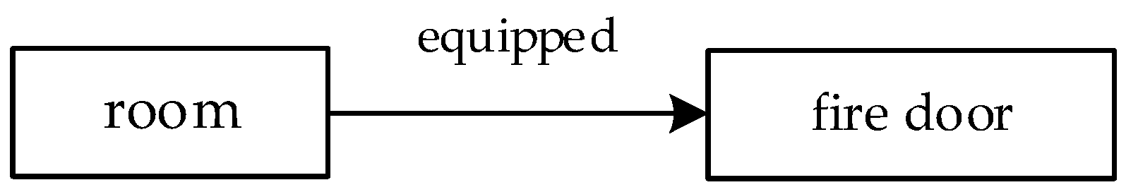
Triples are the most common structure for expressing semantics, and the rules in the specification can be understood as triple semantic expressions. For example, the room must be equipped with a fire door, which is represented by triples closest to the literal meaning, as shown in
Figure 1. The triple indicates that the specification requires a relationship represented by the edge between the room and the fire door. Therefore, each triple is a checking rule. The first element of the triple can be regarded as the object that is constrained in the specification. The edge of the triple represents the constraint mode in the specification, and the latter represents the content to be constrained.
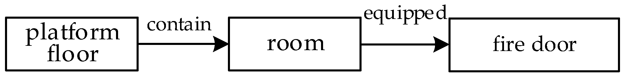
Obviously, the semantics contained in the specifications are not simple. For the above example, there may be more restrictions on the room, such as the room on the platform floor must be equipped with a fire door. The new triple is shown in
Figure 2.
3.2. Triple Representing the Checking Result
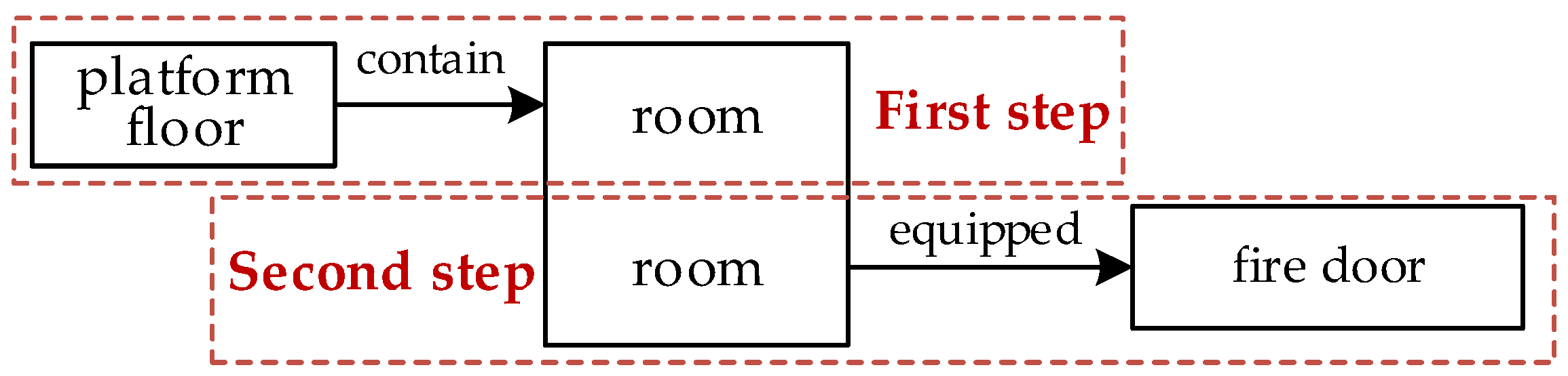
The purpose of compliance checking is to obtain checking results. The result only expresses what is constrained in the specification, no matter how complex the semantics of the specification are. In the previous example, the focus of the expression of the result must be whether the room has a relationship with the fire door. The checking sequence is shown in
Figure 3: the first step is to check whether the room is on the platform floor and the second step is to check the relationship between the room and the fire door. Obviously, the result is only related to the second step. Only one triple is related to the result among all triples in specification representation. Other triples are checked for filtering objects that meet the checking conditions. The purpose of the first step is to determine the room on the platform floor in the previous example. Therefore, the specifications can be represented as a “big” triple in the way of focusing on the expression of results.
The first part of the triple represents checking objects restricted by the specification, the edge represents the constraint mode in the specification and the third part is the checking requirement. In the previous example, the “platform floor-room” triple is the first part of the “big” triple and the fire door is the third part. It can distinguish whether the checked object meets the checking conditions in this way of representation. When the room is not on the platform floor in the previous example, it can be said that it is not compliant with the specification. Although the result is correct, it is obvious that the room does not meet the checking conditions rather than the requirements in the checking results, which is a semantic error in the checking result.
3.3. Code Representation Model
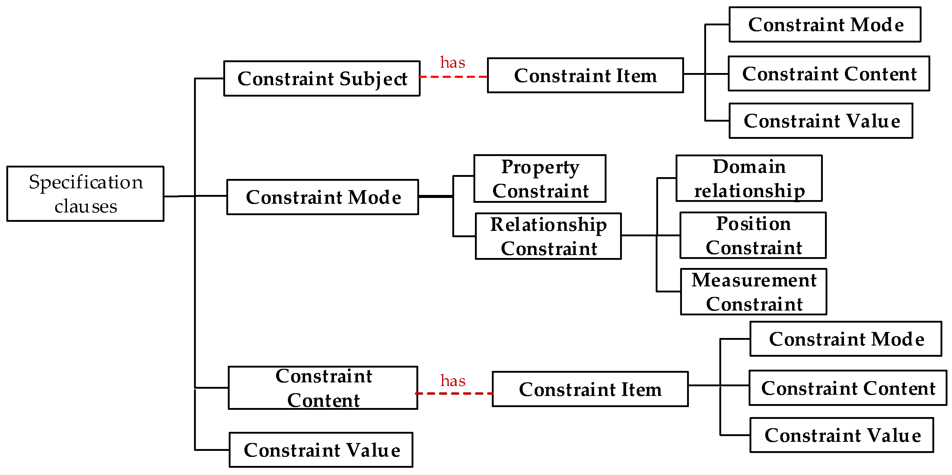
In the above description, one triple represents one restriction. The checked object contains multiple triples to represent the multiple restrictions on the checked object. Similarly, the checking requirements can also contain multiple triples to represent restrictions on checking requirements. Therefore, a code representation model is proposed based on the “big” triple. A specification clause is represented by the constraint subject, constraint mode, constraint content, and constraint value. A triple (a checking rule) is represented as a constraint item that contains constraint value, constraint mode, and constraint content. The code representation model is shown in
Figure 4, and the components are described as follows:
- (1)
constraint subject
Each specification clause can be understood as a restriction on an object which is a constraint subject. There is only one constraint subject in each specification clause. A constraint subject is usually a building component or other physical entity in the building code information. For example, when the width of a door is constrained, the constraint subject is the door. Another function of determining the constraint subject is to establish the correct checking results. Objects that do not conform to the specification can be identified.
- (2)
constraint mode
Constraint mode is to define the type of constraint, which is similar to the function of the comparator. However, there are not only numeric comparators and Boolean comparators in the specification rules but also relationship constraints. Constraint mode is divided into property constraint and relationship constraint. Property constraints are restrictions by common numeric and Boolean comparators. Relationship constraints represent rules through the relationship of objects. Relationship constraints include domain relationship constraints and spatial relationship constraints. Domain relationship constraints are relationships within the architectural engineering domain, such as setup and install. Spatial relationship constraints include position constraints and measurement constraints. The position constraint is a restriction on the spatial location between objects, such as above an object. The measurement constraint is a restriction on the distance between objects.
- (3)
constraint content
Constraint content represents the restricted content of the constraint subject in the specification rule. When the constraint mode is a property constraint, the constraint content is the property. When the constraint mode is a relationship constraint, the constraint content will be other objects.
- (4)
constraint value
Constraint value is a specific numerical or textual value that restricts object entities in specification rules. When the constraint mode is a property constraint, the constraint value is the value of the corresponding restriction. When the constraint mode is domain relationship constraint, there is no constraint value. When the constraint mode is a spatial relationship constraint, the constraint value of the position relationship is the orientation of the constrained position, and the constraint value of the measurement relationship is the constraint distance.
- (6)
constraint item
The constraint item represents other constraints in the specification clause, which are associated with the constraint subject to represent the checking conditions. Each constraint item also includes constraint mode, constraint content, and constraint value. There are often other restrictions on the constraint subject or constraint content in the specification. For example, when the specification restricts the width of the fire door, the door should be regarded as the constraint subject. The door also has other restrictions, that is, the type of door is a fire door. The type of door is not checked requirement of the specification. When the constraint mode is relationship constraint, the constraint content is other object entities. If these object entities also have other restrictions, the constraint items put more restrictions on the constraint content.
4. Spatial Relationship Constraint Checking Method
Spatial relationship constraints are restrictions on the geometric information of objects in building information models. The code representation model can represent spatial relationship which contains position relationships and measurement relationships. The calculation method of geometric information is different for different relationship constraints. This section proposes checking methods for position relationship constraint and measurement relationship constraint.
4.1. Position Relationship Constraint
The position relationships between objects are described by orientation words in code information. The position relationship is divided into relative orientation and absolute orientation. Relative orientation describes the orientation judgment with a certain component as the main body, such as above and below. Absolute orientation describes a fixed direction in the geographic space in which the building is located, such as north or west.
The absolute orientation relationship is checked by determining the position direction of other objects based on the north direction under the unified coordinate system. The north direction will be represented in the building information model. For example, in the IFC data standard, the “TrueNorth” property of the “IfcGeometricRepresentationContext” entity represents the north direction in the form of a vector.
The first step of the checking method for absolute orientation relationship is to obtain the position direction that needs to be judged. Position direction is the relative position of two objects in the specification description. Position direction is calculated based on the coordinates of the center points of the two objects, as in Equation (1).
(x1, y1, z1)—Coordinate value of the center point of object A
(x2, y2, z2)—Coordinate value of the center point of object B
In Equation (1), A and B are determined based on semantic descriptions, such as the window should be on the south side of the room. Object B is the window, and object A is the room.
The second step is to determine the absolute orientation relationship of the object based on the angle between the position direction and north direction. The angle calculation is expressed as Equation (2).
(x0, y0, z0)—position direction vector
(xn, yn, zn)—True north direction vector
The third step of the checking method for the absolute orientation relationship is to determine compliance based on the value of the angle. When the constraint is positive north direction, the value of the angle should be 0. When the specification requires other directions, the true north direction in Equation (2) is modified to the required direction vector. When it is not a positive direction, the value less than 90 degrees is considered as compliance.
The relative orientation relationship is checked based on the coordinate information of the object in the unified coordinate system. The relative orientation is mainly judgment on the upper and lower positions, which can be judged based on the coordinate of the Z-axis of the object. However, this type of position constraint usually has strict position restrictions in the specification description. For example, an evacuation indicatory sign is set above the entrance and exit. The location of the evacuation sign should be above the range of the entrance and exit. Therefore, both elevation coordinates and projection on a plane need to be judged.
The first step of the checking method for relative orientation relationship is to determine the position of an object based on its
Z-axis coordinate value. The judgment way for object A above object B is expressed in Equation (3).
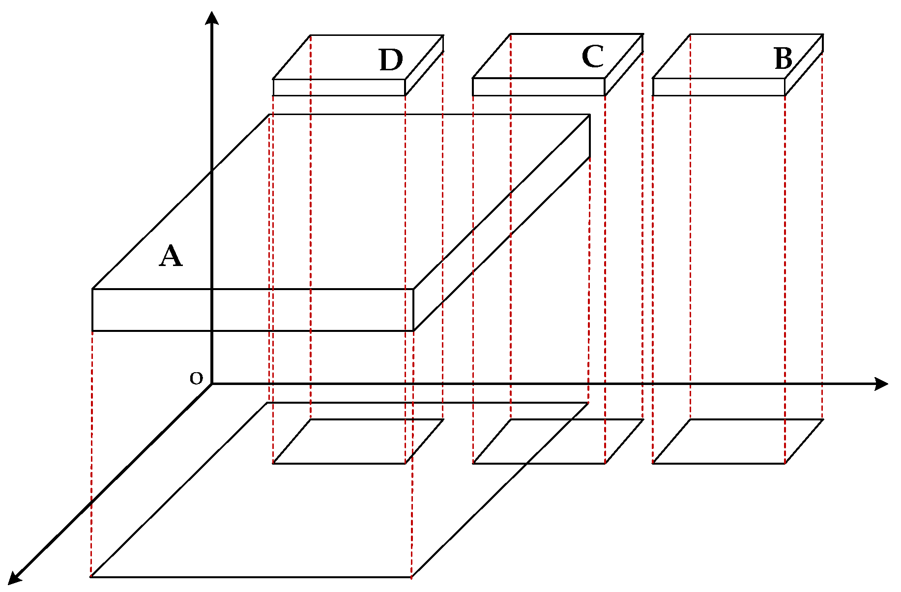
The second step is to judge based on the projection of the object in the plane. The strict upper and lower position relationship is determined by the mutual coverage of projection surfaces. In engineering model, the shape of the component is usually cuboid, and the projection shape is rectangular.
Figure 5 is used to illustrate the judgment method. A, B, C, and D project toward the
X and
Y axes. It can be obtained that B, C, and D are above A from the equation in the previous step. When the projection surfaces do not intersect and there is no inclusion relationship (such as AB), it can be determined that B is relatively above A. The disjoint judgment of rectangles is represented in Equations (4) and (5). If one of the equations is met, the rectangles are considered to be disjoint.
The coordinates of the top left vertex of rectangle A
(x2, y2)—The coordinates of the bottom right vertex of rectangle A
(x3, y3)—The coordinates of the top left vertex of rectangle B
(x4, y4)—The coordinates of the bottom right vertex of rectangle B
If the projection surfaces do not intersect and one surface is contained by another (such as AD), it can be determined that D is strictly above A. The inclusion judgment of a rectangle is expressed as Equation (6).
(x1, y1)—The coordinates of the top left vertex of rectangle A
(x2, y2)—The coordinates of the bottom right vertex of rectangle A
(x3, y3)—The coordinates of the top left vertex of rectangle D
(x4, y4)—The coordinates of the bottom right vertex of rectangle D
If the projection surfaces intersect (such as AC), C can be considered to be diagonally above A. Both formulas mentioned above are not satisfied to be considered the rectangular intersection. In the process of code checking, the appropriate judgment method is selected according to the orientation relationship expressed by the specification semantics.
4.2. Measurement Relationship Constraint
The measurement relationship in code provisions is judgment on distance. Points, lines, surfaces, and bodies, as basic graphical elements, have calculation methods for the distances between them in mathematical geometry. The common distance calculation includes point-to-point distance, point-to-face distance, and face-to-face distance in building information models. The measurement relationship between components is simplified into the calculation of these three types according to the semantic expression of the specification; the distance value is obtained through the calculation to judge the compliance.
- (1)
Center distance judgment
The distance calculation for 3D entities can be considered the calculation of center point distance. This type of specification restricts the distance relationship between components. For example, the spacing of the guardrail is less than or equal to 0.1 m, so the restriction is the distance from the rod to the rod in the guardrail. The center distance calculation is expressed as Equation (7).
(x1, y1, z1)—Coordinate of the center point of entity
(x2, y2, z2)—Coordinate of the center point of another entity
- (2)
Point-to-face distance judgment
This type of specification restricts the distance between objects; one of the objects adds more restrictions. For example, in the distance between the fire hydrant and the ground, the ground refers to the bottom surface of the space where the fire hydrant is located. Therefore, it can be seen as an object changing from a body to an interface of the body. The calculation method is expressed as Equation (8).
(x0, y0, z0)—Coordinate of the center point of entity
Equation (9) is the expression equation for a plane
- (3)
Face-to-face distance judgment
All related objects in this type of specification add more restrictions. For example, the distance between the window sill and the ground, the window sill is the bottom surface of the window object, and the ground is the bottom surface of the space where the window is located. Both objects change from a body to an interface of the body, and both boundary faces are parallel. The calculation method is expressed as Equation (10).
Equation (11) is the expression of two parallel planes.
5. Concept in Code Representation Model
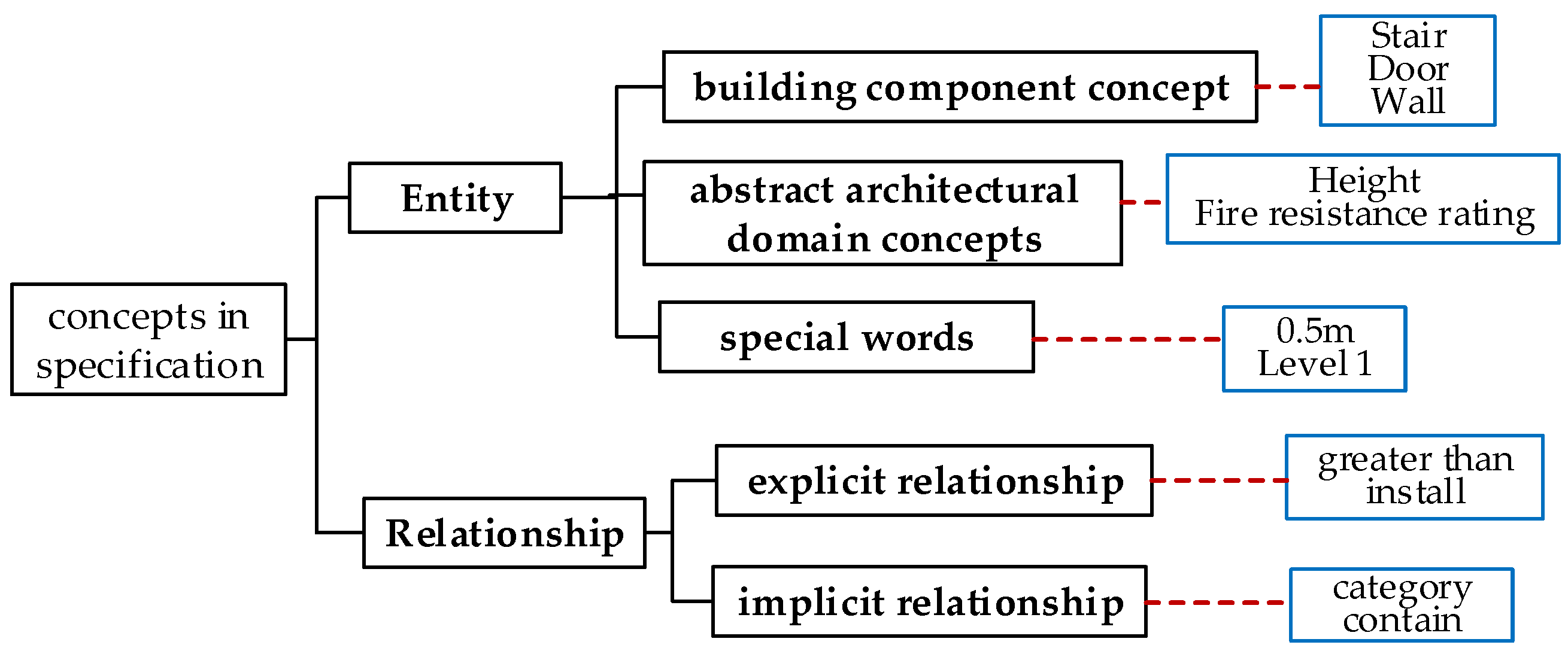
The code representation model represents the rule information in the specification, where the concept of representing specification information needs to be semantically consistent to avoid ambiguity of the same concept between different clauses. Therefore, it is necessary to classify the concept of the entire code information and determine the semantics of the concept. The concepts that can be used in the code representation model are extracted from the specification. The concepts in specification are divided into two categories: entity and relationship through the semantic analysis of specification information, as shown in
Figure 6.
- (1)
Entity
Entities are divided into building components, abstract domain concepts, and special words. Building components are common physical entities in the specifications, such as escalators and rooms. Abstract domain concepts are usually characteristic nouns that express the property of building components, such as fire resistance rating and design service life.
Special words represent value words, including numerical values and literal values in the specification, such as 100 years, level 1, and 0.5 m. It should be noted that the literal value is different from the abstract domain concept. In general, the literal value is the property value and abstract domain concept is the property name.
- (3)
Relationship
Relationship is the concept of expressing the semantics between entities. There are two kinds of relationships: explicit relationships and implicit relationships.
Explicit relationships are relationships that appear in specifications. The common relationships are numeric and Boolean comparators; another part is the concepts in the field of architecture, such as “setting”, “in”, and “of”. The ambiguity of the same vocabulary (such as the expression of positional relationship: “in”) and the consistency of different vocabulary (such as “equip”, “setting”) require special attention. One of the most influential factors is the way of language expression. The context of relationships is considered for consistency.
Implicit relationships are relationships hidden between entities, most of which need to be defined. There may be no conjunction between two concepts in the specification description (such as in Chinese expression). Implicit relationships need to be supplemented by researchers based on domain knowledge. For example, “the fire resistance rating of the control center”, the relationship between the control center and the fire resistance rating is set as property relationship. The consistency of relationships is also considered in supplementing implicit relationships.
One of the reasons for the difficulty in extracting code knowledge concepts is the different levels of domain knowledge of researchers. The same concept may become a different concept if understood differently, which causes semantic inconsistency. Therefore, the concept definitions in the building information ontology ifcOWL are referenced, and there is a unified standard for defining code concepts in knowledge extraction.
6. Check Rule Generation
Compliance checking results are obtained by using the checking method in building information according to code rules. The code representation model is the representation of specification semantic information, which provides rules for compliance checking. The necessary condition for checking rules to be executed on building information is that there is a corresponding concept mapping between the building information and the code representation model. IFC and its ontology form ifcOWL are currently popular building information standards. Therefore, the mapping between the code representation model and the building information ontology ifcOWL can be established with the help of the building information representation in ifcOWL; then, SPARQL or SWRL rules are directly generated through the code representation model to implement compliance checking.
The first step, the mapping between the concepts in the code representation model and ifcOWL, is established and can be divided into five categories.
The first category is a common architectural concept, which can directly correspond to the classes in ifcOWL, such as doors corresponding to IfcDoor or windows corresponding to IfcWindow.
The second category is some architectural component concepts with special functions, which correspond to the classes that need to add special restrictions in ifcOWL. For example, the escalator corresponds to IfcTransportElement in ifcOWL and the PredefinedType property value is ESCALATOR.
The third category is the concept of property. Property has different representation patterns according to the type of value, such as property single value (IfcPropertySingleValue) or property list value (IfcPropertyListValue). Property name restriction needs to be added in property mapping.
The fourth category is the special words, which include numerical values with units and literal values. Generally, special words are used as property values and the unit is defined by the global unit IfcUnitAssignment in IFC file. The inconsistency between the global units and the units in the specification is not discussed since the units in the specification are generally SI units. All values with units can correspond to ifcOWL class, such as length corresponding to IfcLengthMeasure and speed corresponding to IfcLinearVelocityMeasure. Common type mappings are shown in
Table 1 and literal classes correspond to IfcLable.
The fifth category is the relationship in the specification. The actual semantics of explicit and implicit relationships in the specification knowledge extraction is determined according to the context. One type of relationship corresponds to the IfcRel relationship entity—for example, the spatial relationship between the floor and the building corresponds to IfcRelAggregate. Another type corresponds to a pattern. For example, property relationship means that the entity is associated with IfcPropertySet, and IfcPropertySet is associated with IfcProertySingleValue (or other property value types). The whole series of associations correspond to the property relationship in the specification, which represents the entity that has the property. The position and measurement relationships in spatial relationships are generally not defined in the original model, which are obtained by computing the geometric data. Two relationship entities are selected to represent the spatial relationships. IfcRelConnectsElements represents the relationship between components, and IfcRelReferencedInSpatialStructure represents the relationship between component and space. Some of the relationships in the specification are listed in
Table 2.
The constraint subject, constraint content, and constraint value in the code representation model are regarded as nodes, and the constraint mode is regarded as edges, such as the code representation model can be expressed in the form of a graph. The graph of the code representation model can be transformed into checking rule through the mapping between ifcOWL and the code representation model.
SPARQL query is to query the information conforming to the rules from the existing information; SWRL rules are to reason about the existing knowledge in the ontology and obtain the checking result. Reasoning is a necessary method to obtain new knowledge in knowledge engineering. Moreover, the specification knowledge used in compliance checking can provide more semantic information for the development of code knowledge graphs in the future. Therefore, SWRL rule reasoning is selected as the checking method.
The second step, the specification concepts that can correspond to ifcOWL, are mapped into the corresponding SWRL rule form. The above five types of mapping can correspond to the SWRL rules.
The first category that directly corresponds to ifcOWL class can directly generate the SWRL rule representing the instance of the class, such as the window corresponding IfcWindow(?x), where ?x represents the instance of the IfcWindow class.
The second category corresponds to the ifcOWL class that requires special restrictions. The corresponding restrictions are added in SWRL rules according to the content of the restrictions, such as escalators, and the corresponding rule is IfcTransportElement(?x)∧ PredefinedType(?x,ESCALATOR).
The third category is SWRL rule of property representation. It is similar to the second category—the property is represented by IfcProertySingleValue, and the restriction is added for property name. The corresponding rule is IfcPropertySingleValue(?x)^Name (?x,?y)^hasString (property name).
The fourth category is numerical and text words in special words, which directly correspond to the SWRL form according to the corresponding ifcOWL type. For example, 10 m is IfcLengthMeasure(?x)^hasDouble(?x,10).
The fifth category is relationship. When the concept corresponds to an IfcRel relationship entity, the restrictions representing the association need to be added to the SWRL rule. For example, the relationship between floors and buildings is IfcRelAggregate whose corresponding SWRL form is IfcBuilding(?a)∧IfcRelAggregates(?r)∧IfcbuildingStorey(?c)∧RelatingObject(?r,?a)∧ RelatedObjects(?r,?c). When a concept corresponds to the pattern, the corresponding association can be added to the SWRL rule according to the ifcOWL class contained in the pattern, which is equivalent to a combination of multiple “IfcRel” relationships. The spatial relationship representation is necessary to map not only the relationship entities representing spatial relationships but also the types of spatial relationships, such as orientation or distance.
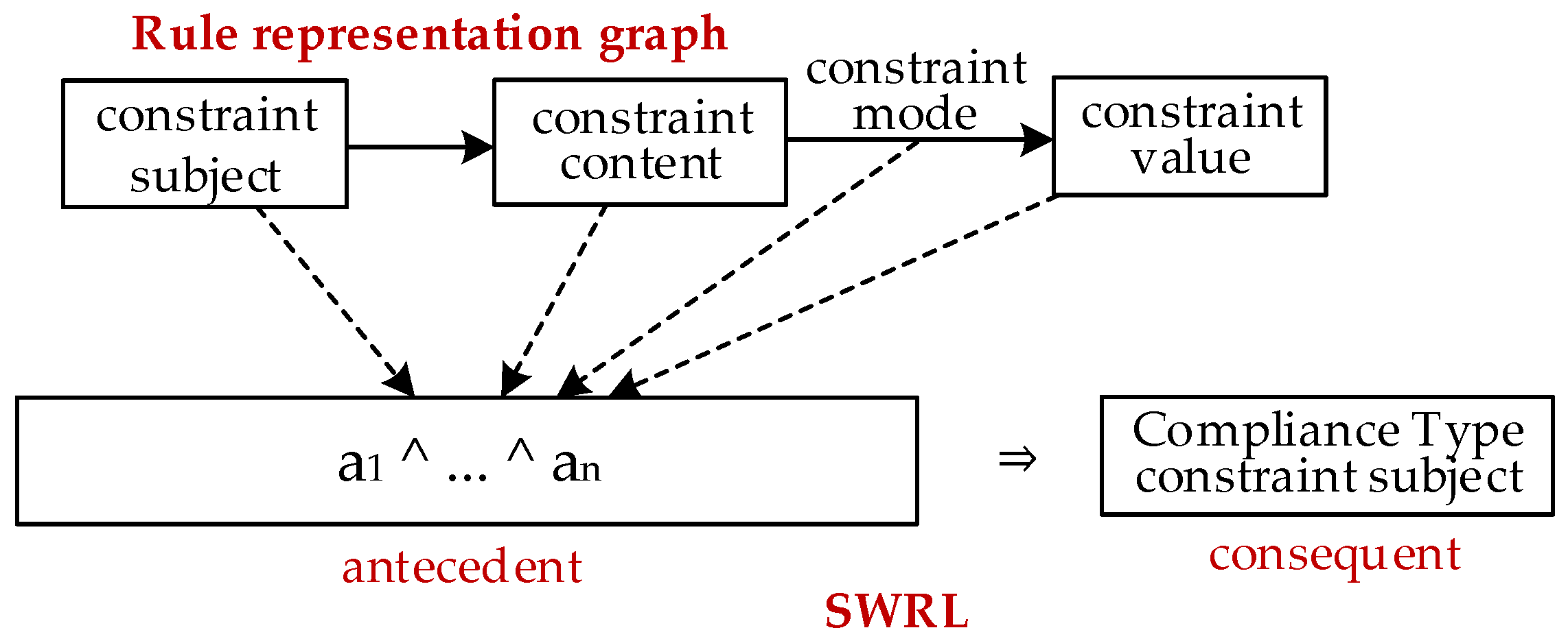
The SWRL rule includes the antecedent regarded as a condition and the consequent regarded as a reasoning result. The antecedent is the representation of the rules generated through mapping. The consequent is the checking result. The expression form of checking result is whether the constraint subject in the code representation model conforms to the checking requirements and whether the class of result needs to be added to the ontology. The way of conversion is shown in
Figure 7. The code representation model can be directly converted into SWRL rules that can be used for checking in this way, which realizes automatic compliance checking.
7. Case Study
The code for design of Metro (GB50157-2013) [
50] is one of the important codes in the metro construction domain in China, which covers at least 14 specialties. The code for design of Metro contains not only the provisions of the elements in the metro station but also the specifications for trains, subgrades, lines, and other nonconstruction fields. The code clauses of different constraint modes and different constraint conditions of the constraint subject are selected to verify the method of code representation, which are shown in
Table 3. In constraint type, an unconstrained subject indicates that the object constrained by the specification has no other constraint content and a constrained subject indicates that the object constrained by the specification has other constraint content. The experiment is divided into two parts. The first part is to generate SWRL rules that can be used for checking through the code representation model of specification clauses, and the second part is to execute compliance checking.
7.1. SWRL Rules Generation
- (1)
Code knowledge extraction
The concept in the code needs to be extracted as the content in the code representation model. The concepts are classified into different entities and relationships according to the method of code knowledge extraction through the identification by domain experts. The relationship and entity of each clause are shown in
Table 4. Some relationships between the entities are hidden because of the Chinese description. For example, the relationship between the escalator and the lifting height is not described in Clause 25.1.15, so it is necessary for domain experts to complement the property relationship.
- (2)
Code representation model
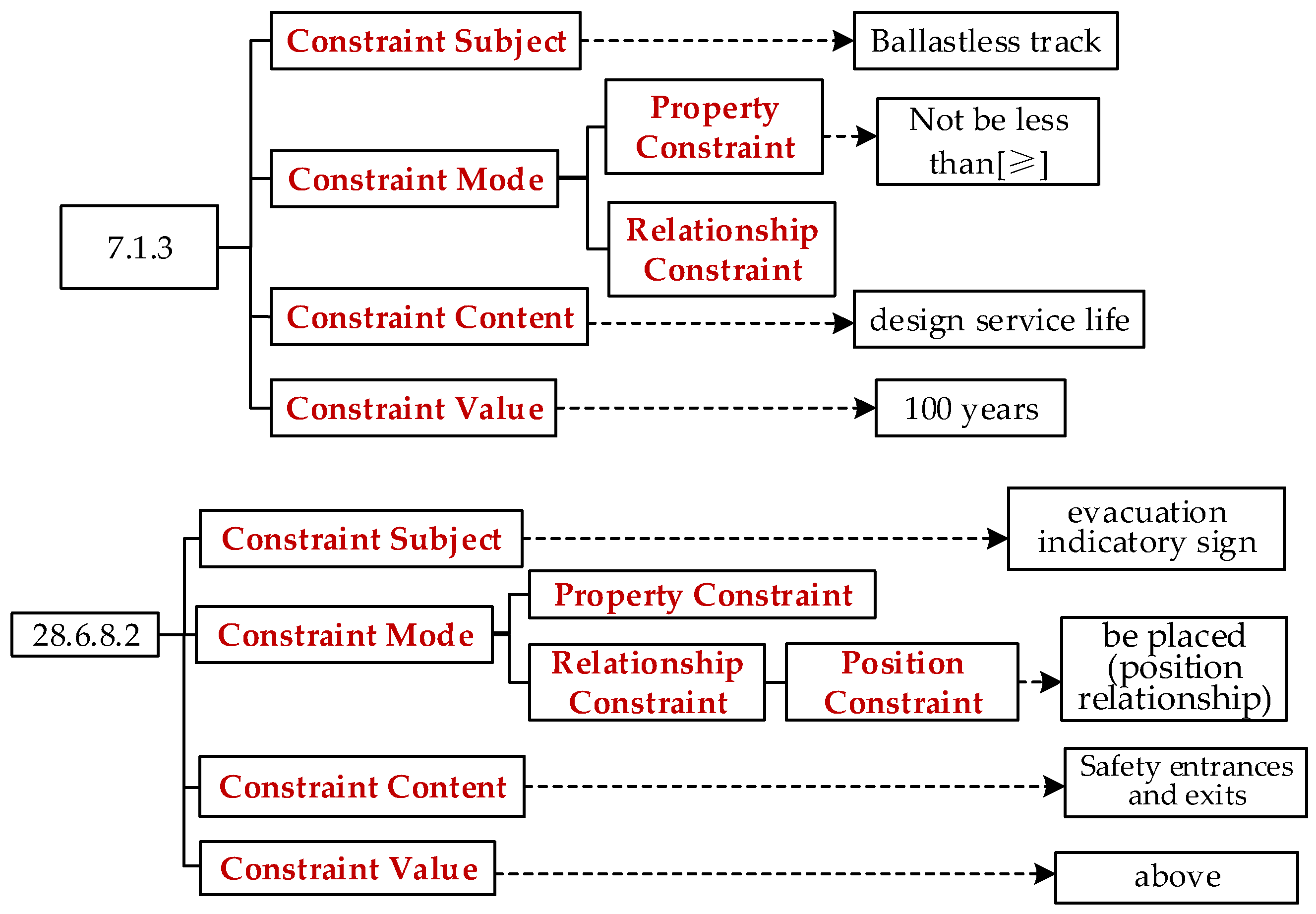
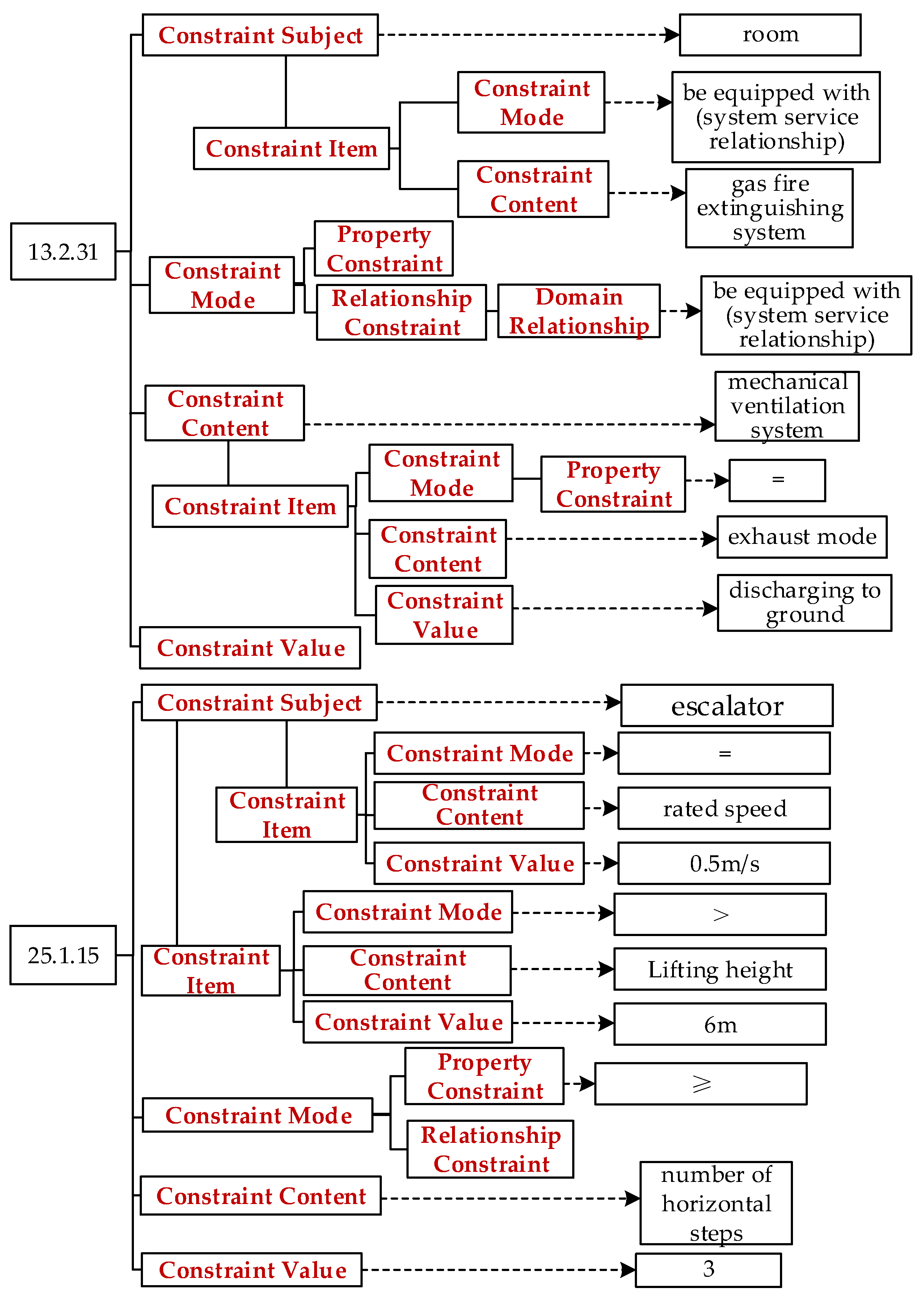
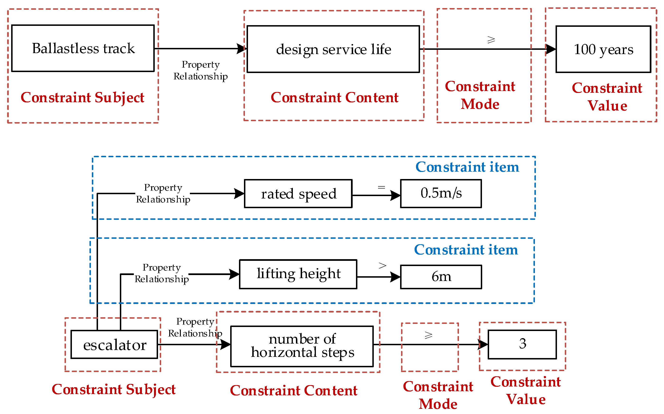
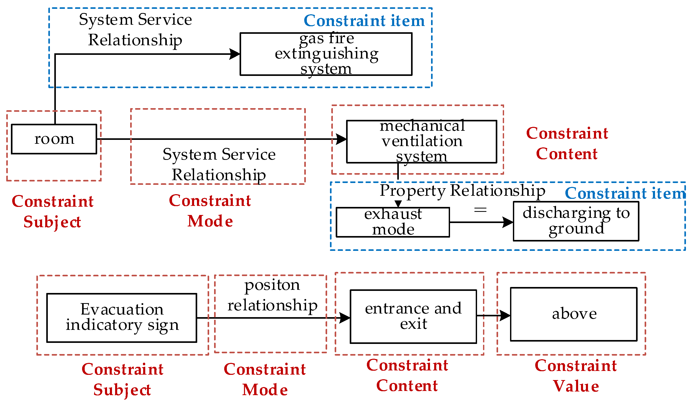
The code concepts will be used as the constituent elements of the code representation model, which is established according to the specifications semantic. Clause 7.1.3 and 28.6.8.2 have no other constraint contents on constraint subject, as shown in
Figure 8. Clause 25.1.15 and 13.2.31 have other constraint content on the constraint subject, as shown in
Figure 9.
- (3)
Code representation model mapping
First, the mapping relationship between the concepts in the code representation model and ifcOWL is established. The concepts in these clauses are mapped to ifcOWL. All properties concepts are mapped to “IfcPropertySingleValue Name ONLY {Property Name}” and other concepts are represented in
Table 5.
Then, the code representation model is converted into a graph, which is easy to store and generate SWRL rules. The constraint mode of Clause 7.1.3 and 25.1.15 is property constraint, as shown in
Figure 10; Clause 13.2.31 and 28.6.8.2 are relationship constraints, as shown in
Figure 11.
Finally, the graph is converted into SWRL rules according to the mapping. The ifcOWL object corresponding to each concept in the graph is transformed into the SWRL rule that connects in the order of the graph. Newly added class compliance represents instances that conform to the checking. Four clauses are selected from different types in
Table 3, and the generated SWRL rules are shown in
Table 6.
7.2. Compliance Check Experiment
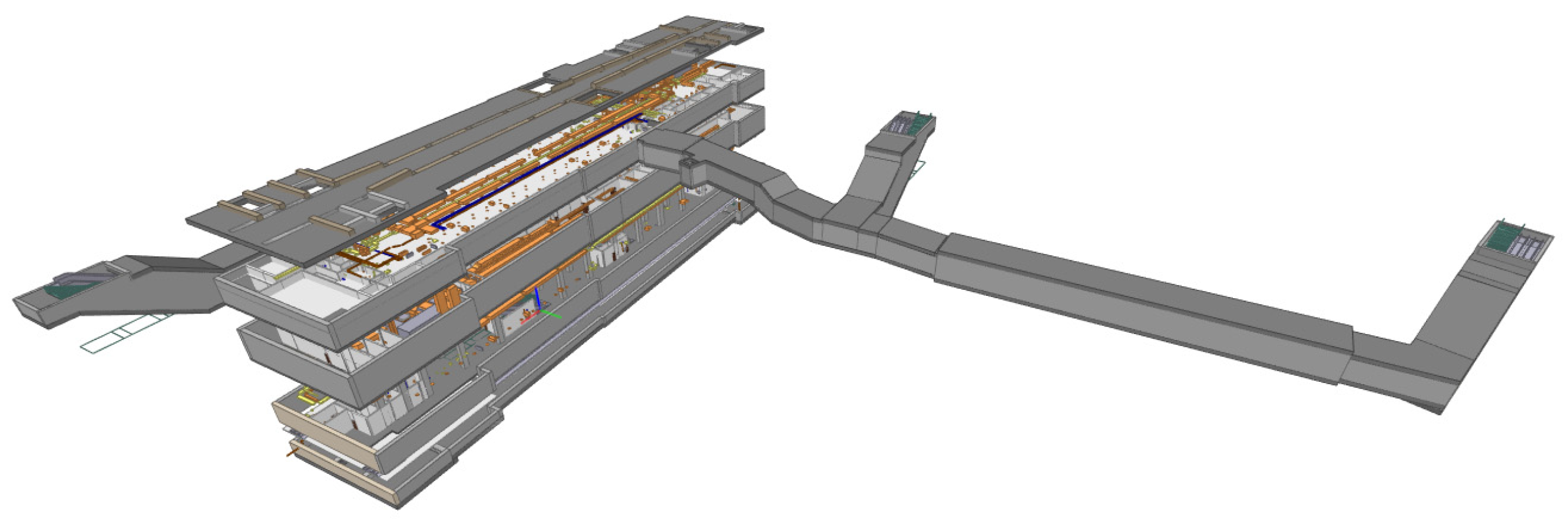
The test model is a subway station in a city in China, which contains most of the components of the subway station. The file format is IFC. The model is shown in
Figure 12 and the display tool is BIM Vision [
51]. IFC data are converted to RDF through IFCToRDF tool [
52]. Spatial relationship checking requires extracting geometric data to calculate according to different spatial relationship checking methods and establishing corresponding spatial relationships based on the calculated results before conversion. Protege, a visual ontology development tool, is used to perform compliance checking by importing SWRL rules to reason.
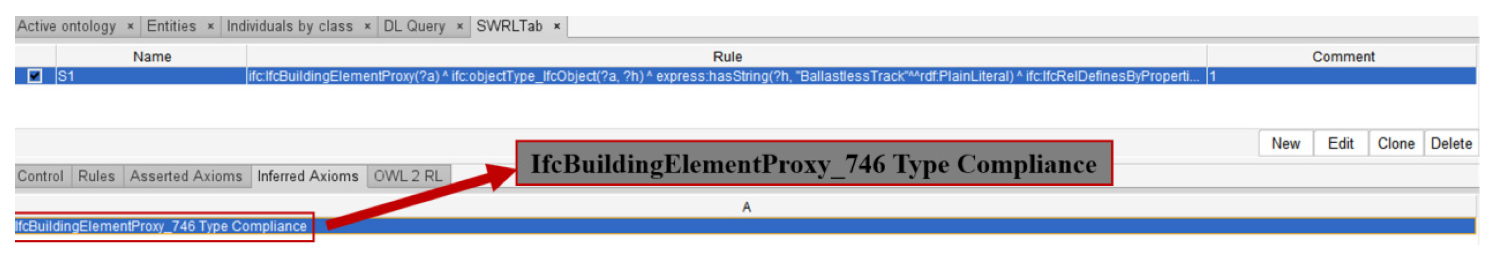
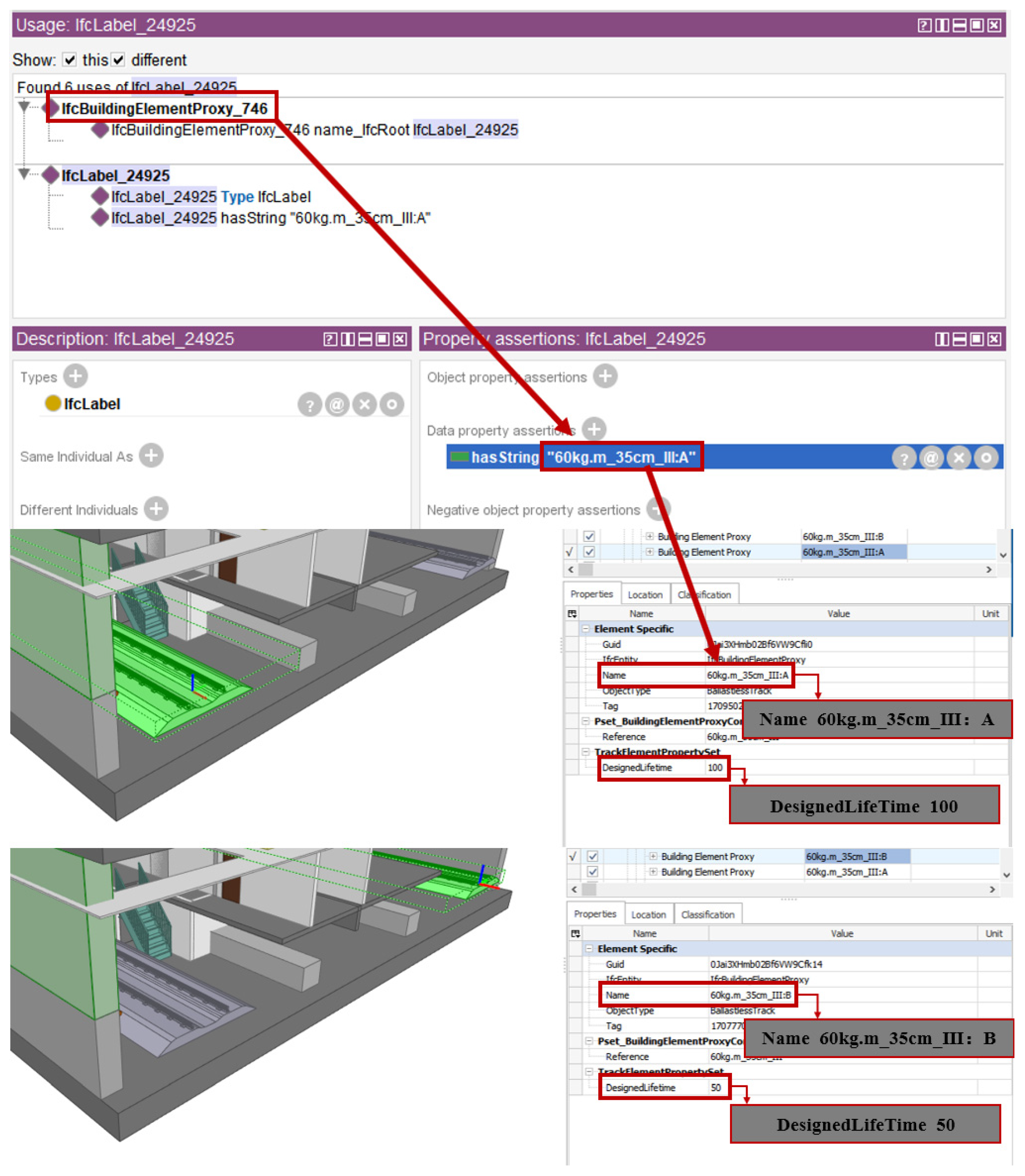
The reasoning result of Clause 7.1.3 is shown in
Figure 13, where “IfcBuildingElementProxy_746” conforms to the rule. The corresponding name can be obtained from its name attribute value: “60 kg.m_35 cm_III: A”. The design service life of the two track components in the model is 50 and 100, respectively, which are consistent with the checking results, as shown in
Figure 14.
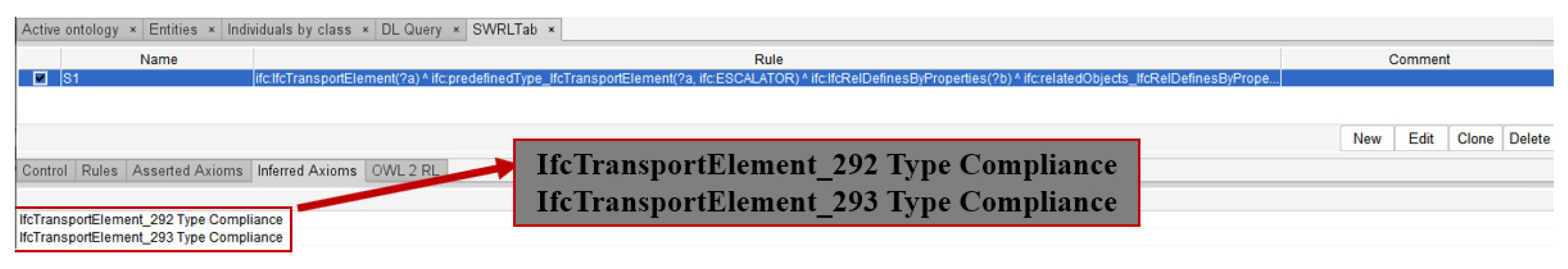
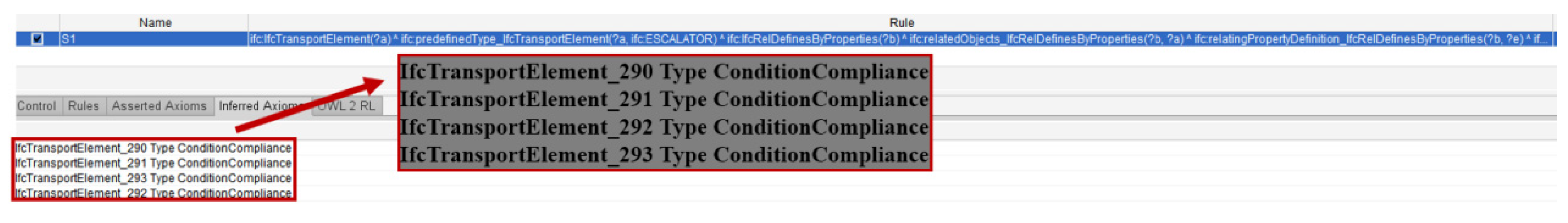
The reasoning result of Clause 25.1.15 is shown in
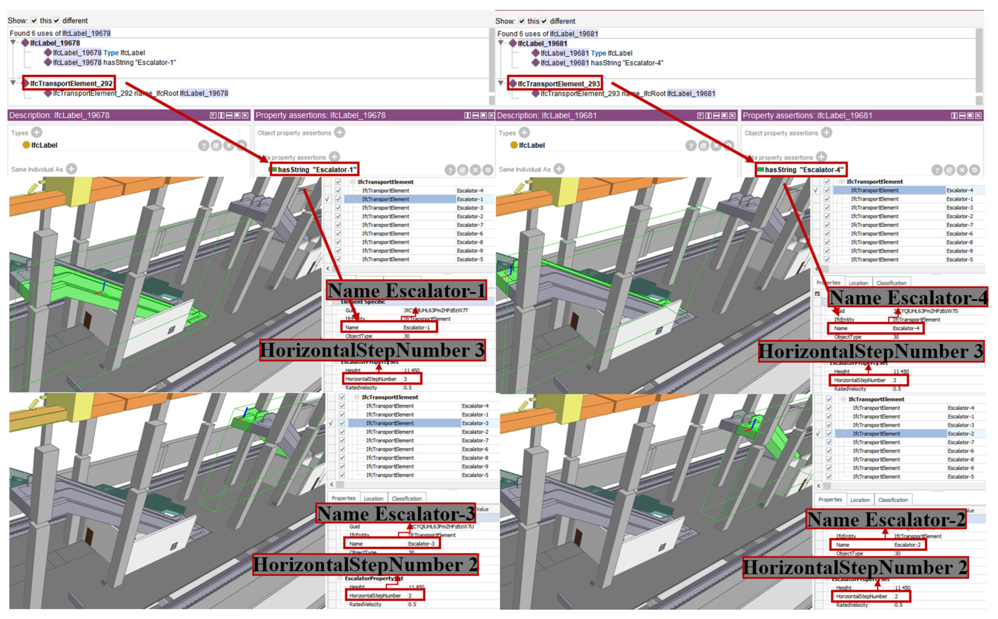
Figure 15, where “IfcTransportElement_292” and “IfcTransportElement_293” conforms to the rule. The corresponding name can be obtained from its name attribute value: “Escalator-1”, “Escalator-4”. It can be seen from
Figure 16 that “Escalator-1” and “Escalator-4” meet the specifications, whereas “Escalator-2” and “Escala-tor-3” do not meet the specification because the number of horizontal steps is 2.
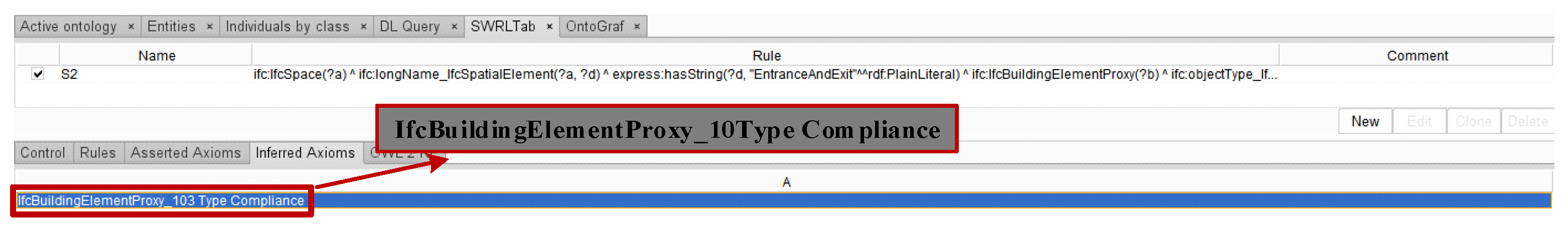
Clause 28.6.8.2 is used to check spatial relationship between the object and space. The premise of reasoning for spatial relationship constraints is that the corresponding relationship has been established based on the calculation method of spatial relationship constraints. The reasoning result is shown in
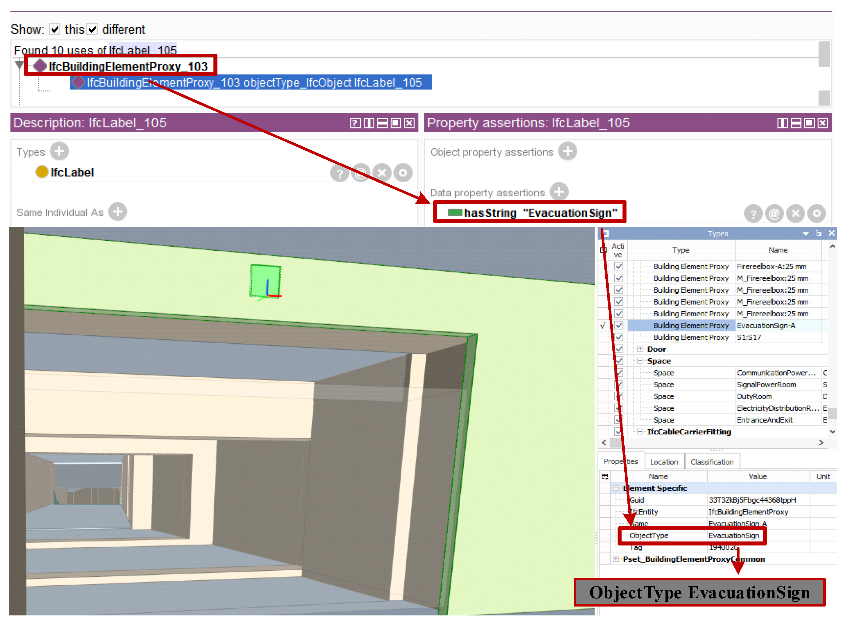
Figure 17, where IfcProxyElement_10 conforms to the rule. Its ObjectType property value is “Evacuation Sign”. It can be seen in
Figure 18 that the evacuation indicator sign is above the entrance and exit.
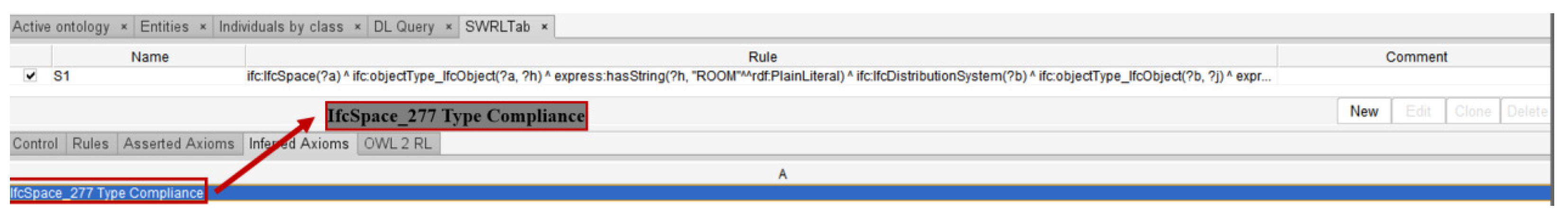
The reasoning result of Clause 13.2.31 is shown in
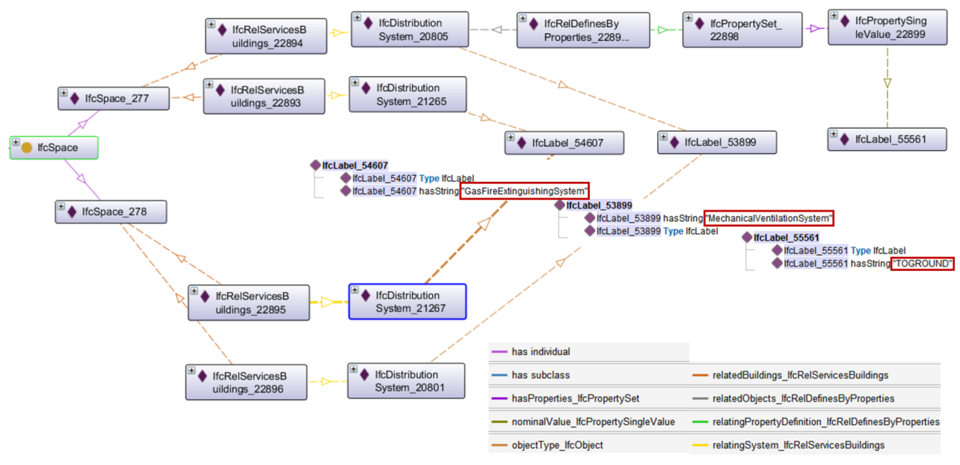
Figure 19, where “IfcSpace_277” conforms to the rule. The relationship in the RDF file is represented by the OntoGrap in Protege, as shown in
Figure 20. “IfcSpace_277” and IfcSpace_278 are equipped with gas fire extinguishing and mechanical ventilation systems, but only the mechanical ventilation systems related to “IfcSpace_277” has the property of discharging to the ground.
The above experiments verify the feasibility of compliance checking from the code representation model to SWRL generation. However, this checking method can only check the objects that meet the specifications and cannot obtain the objects that do not meet the specification or the objects that do not meet the checking conditions.
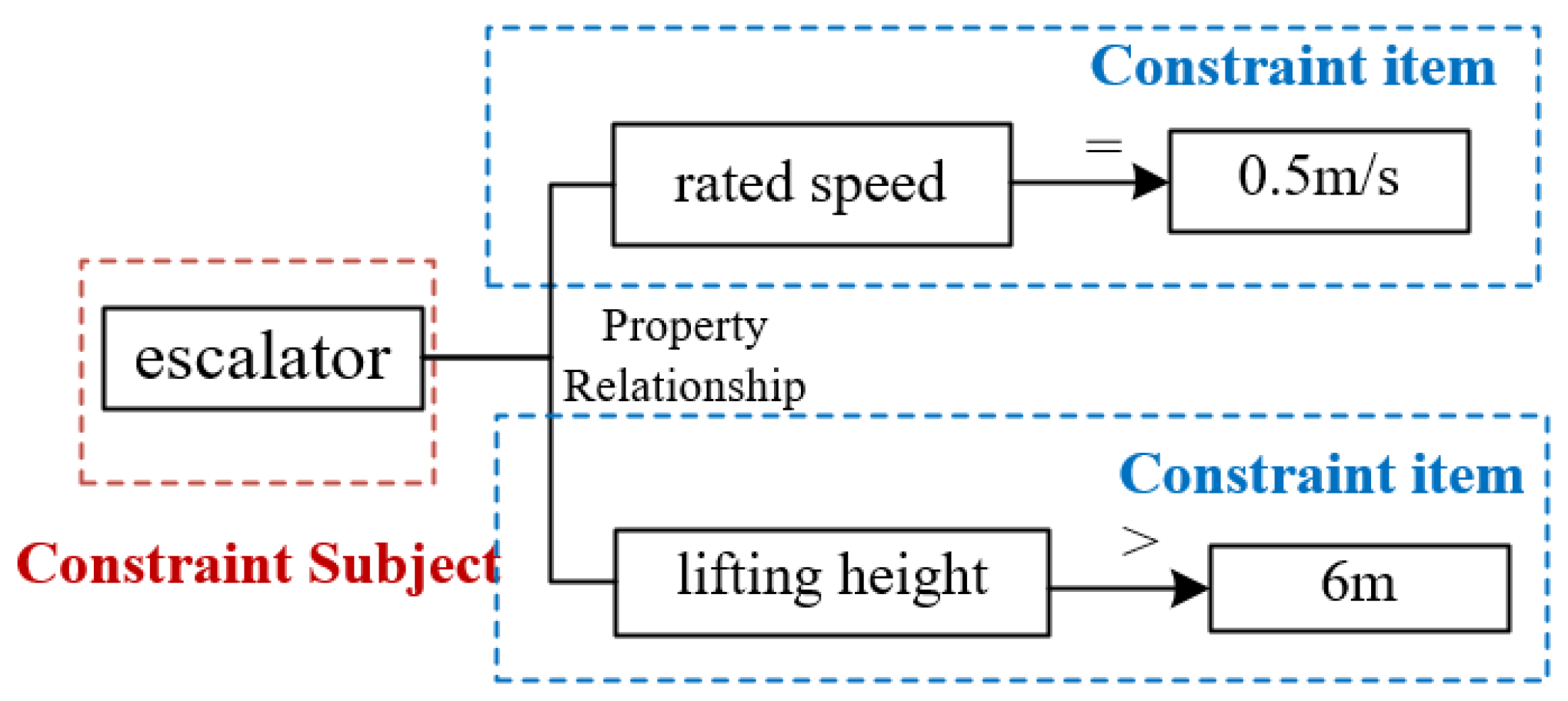
The constraint subject and constraint item in the code representation model proposed in this paper can further check this kind of object. Clause 25.1.15 is used as an example to illustrate the checking process. There is a total of nine escalators on the entrance, exit, and platform floor in the model. The graph of the constraint subject and constraint item obtained from the code representation model is shown in
Figure 21.
It can be known from the code representation model that the restriction on the number of steps is valid only when the lifting height of the escalator is greater than 6 m and the rated speed is 0.5 m/s. The constraint subject and constraint items are regarded as the checking requirements which are converted into the corresponding SWRL rule, and a new class is added to represent an instance that meets check conditions. The result is shown in
Figure 22, where four objects are obtained. The corresponding escalator names are: Escalator-1, Escalator-2, Escalator-3, Escalator-4; Escalator-1 and Escalator-4 have appeared in compliance checking. More escalator properties are shown in
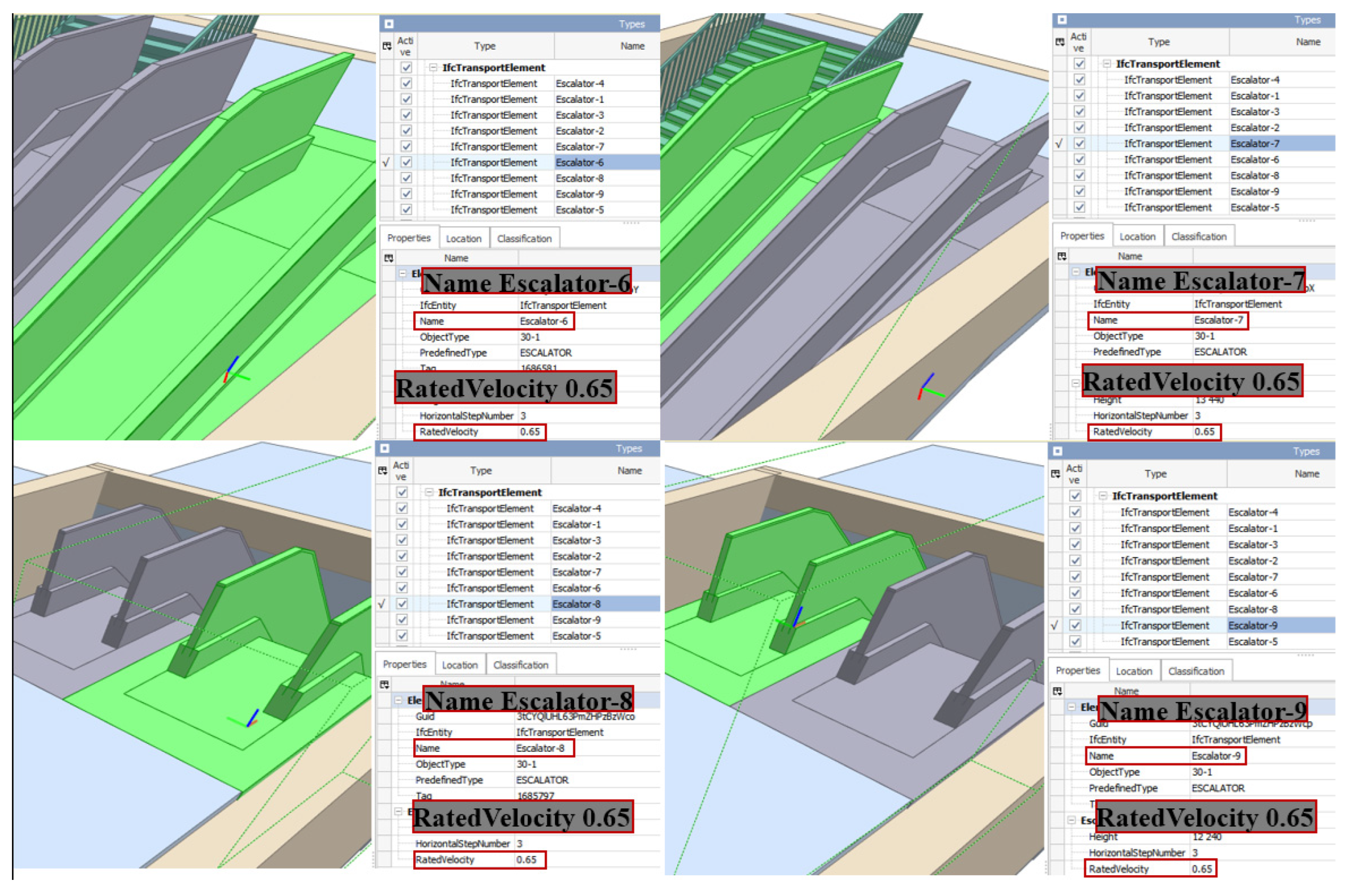
Figure 23. Only Escalator-1,2,3,4 meet the conditions, and the rated speed of the rest of escalators is 0.65, which does not meet the requirements of compliance checking. Therefore, only Escalators-2 and Escalators-3 do not meet the specifications. The compliance checking results of the other five escalators should be represented as not meeting the current code checking conditions rather than noncompliance.
7.3. Experiment Discussion
The experiments completely demonstrate the process from the code clauses to obtaining the compliance checking results. The correctness of the compliance checking results also indirectly proves the feasibility of the code representation model proposed in this paper. Other current code representation methods mainly represent numerical and Boolean relationships. The code representation model in this paper can represent spatial relationships and abstract relationships in engineering. The constraint subject and constraint content are separated in the code representation model. It is able to solve the judgment of components that do not meet the specification checking conditions, which is often overlooked in other code checking. The check requirements consisting of the constraint subject and constraint item can support more semantic check results, which is also achieved in the last experiment.
Since the compliance results are obtained through SWRL rule reasoning, the objects that meet the compliance only are obtained generally. The noncompliance objects can be obtained through the difference set between the object set that meets the specification checking conditions and the compliance object set. It is more appropriate to use SPARQL query statements if directly obtaining noncompliance objects. When the code representation model and mapping are known, SPARQL statements are obtained as easily as SWRL rules.
The checking of relationship constraints in the experiment is related to these relationship representations in building information ontology ifcOWL, and different building information ontologies have different definitions of relationships in the specification. Therefore, the transformation from the relationship representation in the specification to the relationship representation in the building information ontology requires manual verification. At present, some work of manual processing cannot be avoided in compliance checking.
In addition, the checking process should be an important part of compliance checking. Compliance checking should first determine the objects that meet the checking conditions and then carry out compliance checking, so that the checking result of each object can be expressed correctly. The experiment in this paper does not strictly follow this checking process in order to verify the feasibility of the method but directly carries out the compliance checking.
8. Conclusions and Future Work
Using Semantic Web technology to gradually realize automatic compliance checking is a current research trend in the field of compliance checking. The first step in compliance checking is to transform the specification clauses described in natural language or more professional vocabulary into computer understandable rules, which is the main challenge at present. It is very difficult to establish a specification representation model due to highly professional content and complex semantic logic description. Although some researchers have proposed specification representation models suitable for some specifications, there are still some problems. On the one hand, there are not only numerical and Boolean judgments but also many relationship judgments between components, such as spatial relationship constraints. On the other hand, the distinction between checking conditions and requirements is often ignored. The semantics in the specification clauses are complex and there are many constraints on the components. Some of these constraints may constitute the checking conditions and some are actual checking requirements. The components that do not meet the conditions cannot completely be considered noncompliant. Therefore, a code representation model aiming at checking results is proposed based on a triple structure. The code representation model is composed of five parts. The combination of the constraint subject, constraint mode, constraint content, constraint value, and constraint item can completely represent the specification rules. The constraint mode includes relationship constraints, and the constraint items can distinguish checking conditions and requirements. Moreover, the concept of code knowledge is classified and extracted to ensure the semantic consistency of the concept in the code representation model. In order to realize compliance checking, ifcOWL is used as building information ontology, and the mapping between ifcOWL and specification concepts is established for converting the code representation model into SWRL rule. Finally, the code representation model is verified by code clauses with different constraints, which can realize the automatic generation of checking rules.
Although the code representation model can represent more complex specification clauses and improve the accuracy of checking results, there are still some specifications that cannot be described. When the constraint subject is not a single object, it is difficult to represent through the code representation model. For example, two fire compartments should be separated by fire doors. The specification constrains the content between two fire compartments. The code representation model should be extended to be able to apply more specification representations in future work. This paper uses ifcOWL as the building information ontology. Although ifcOWL is currently a popular building information data standard, there is still some information that cannot be fully expressed. There is no relatively complete building information standard, which is also a problem encountered in compliance checking currently. In the future, ifcOWL can be extended to support more building information concepts and provide complete information representation for compliance checking. Semantic Web or knowledge engineering has been applied to various fields, and semantic technology is also the most appropriate method to solve the current compliance checking. The research on the semantic expression of code clauses can not only promote knowledge representation in the field of building information but also provide the basis for the establishment of knowledge graphs in the field of specification in the future.

 ,
, 


