1. Introduction
An important direction in the development of modern technologies is the saving and storage of energy. Thus, the net zero energy buildings direction is actively developing in construction, which implies net zero energy consumption when using renewable energy sources. For energy storage and to improve thermal inertia of building envelope, building elements and air conditioning systems containing phase-change materials are used. The use of such materials in suitable thermal conditions helps to reduce temperature fluctuations in the structure and, as a result, reduce energy costs [
1,
2]. A feature of phase transitions is the release or absorption of a large amount of energy at an almost constant temperature. The most commonly used organic compounds are waxes, paraffins and fatty acids. These materials are non-toxic, chemically stable, and have low-thermal conductivity and high-latent heat [
1,
3,
4].
Phase transitions can be used for passive temperature control in many technical applications. The use of PCMs in cooling Li-ion batteries allows to increase the service life, since their operating temperatures must not exceed the temperature range 20 °C–60 °C, therefore, such systems use PCMs with melting points no higher than 55 °C [
5,
6,
7]. In [
8], RT27 coupled with aluminum foam has been studied for passive thermal management. The effect of the PCM layer thickness on the battery performance has been evaluated for 5000 s. Analysis of the results has shown that the smallest thickness for continuous operation is 3 mm. At a thickness of 2 mm, the material can be managed to completely melt and the temperature can begin to rise sharply. With a larger layer of PCM, the control temperature does not exceed 27 °C. The efficiency of using phase transitions will depend on the thermophysical properties of the selected materials and the design component in conjunction with the thermal operating conditions. Thus, the study of the PCM effect on heat transfer in a building structure is divided into a wide range of tasks due to a large number of factors. It should be noted that a PCM-based building envelope shows different efficiency in different climatic zones. Thus, Marin et al. [
9] have conducted a numerical analysis of the effectiveness of using PCM in a building under different climatic conditions. Numerical simulation has been carried out using the EnergyPlus software package. It has been shown that the integration of PCM into the building envelope allows saving up to 271 kWh annually, however, in the cold climatic conditions of the northern regions, the total cooling and heating savings per year does not exceed 20 kWh.
Al-Rashed et al. [
10] have performed simulations and heat transfer in a building envelope with a 20 mm PCM layer under Kuwait City weather conditions. The studies have been carried out for all months of the year with three different PCMs: RT-31, RT-35 and RT-42. It has been shown that the annual heat exchange can be reduced by 25.71%, 9.57% and 4% when using RT-31, RT-35 and RT-42 materials in the roof and walls of the building, respectively. The thermal performance of a PCM-embedded brick in a Mediterranean climate has been studied numerically by Hamidi et al. [
11,
12]. It has been shown that a PCM with a phase transition temperature of 26 °C can save up to 56% of the energy to maintain a room temperature of 26 °C [
11]. The influence of the PCM position in a wall of two layers of brickwork with an air gap has been investigated by Hamidi et al. [
12]. As a result of the simulation, it has been found that the PCM position in the inner brick layer is the most effective in terms of thermal resistance, while the heat flux reduction up to 97% has been observed.
The main objective of using PCM is to reduce temperature fluctuations. In addition to restraining the temperature difference, phase transitions make it possible to accumulate a certain amount of energy by absorbing both thermal energy and radiation energy; the absorption intensity is determined by the volume of the material and the geometry characteristics of the system. The influence of melting on the cooling of a room (0.45 m × 0.45 m × 0.45 m) has been experimentally and numerically studied by Abbas et al. [
13]. The wall with PCM tubes has been oriented to the south, which makes it possible to absorb the maximum amount of solar energy. Researchers are able to achieve a temperature reduction of 4.7 °C, compared to the case without PCM. Also, a decrease in index of thermal load leveling (TLL) [
14] by 23.84% has been obtained as:
. This shows a significant decrease in temperature fluctuations inside the system. In addition, the difference in reaching peak temperatures on the outer and inner surfaces has been found when conducted for 2 h. In ventilation systems, the addition of PCM unit can absorb up to 50% of heat [
15,
16], and in combination with a glazing unit and windows, the thermal performance of buildings can be increased [
17,
18].
Increasing the amount of material will have a positive effect on productivity. However, it is worth noting that the melting rate of the material is limited; in addition, the cost of the material should also be considered. To intensify the heat transfer between the base and the phase-change material, the heat transfer surface area can be increased. Therefore, in the study by Al-Yasiri and Szabó [
19], it has been shown that an increase in the number of cells contributes to a decrease in peak temperatures and an increase in time lag. Aluminum capsules, the total volume of which is constant, can increase the heat exchange with the PCM through increasing the surface area. Increasing the heat transfer area can also be conducted by increasing the number of PCM layers [
20,
21]. Saxena et al. [
21,
22] have investigated the effect of PCM on the thermal resistance of brick blocks. The authors have prepared samples encapsulated in a finned-sheet metal case with the PCM at close melting points. For PCM, eicosane with a melting point in the range of 36 °C–38 °C, and OM35 with a melting point of
Tm = 35 °C have been considered. The case with two PCMs located in parallel layers has also been studied. The dual PCM layer has shown a temperature drop of 9.5 °C, while the single layer has shown 6 °C. During the day, the reduction in heat loss is 60% in the case of dual PCM and 40% for single PCM. In addition, doubling the thickness of the PCM layer with metal fins allows for increasing the temperature of the brick. A 50% reduction in heat flux has been obtained by Jia et al. [
23]. In three-dimensional modelling of heat transfer in a brick with inserts of thermal insulation material, PCM and air has been carried out by the authors. It has been shown that thermal insulation material can significantly improve thermal resistance, while PCM increases thermal inertia. Gao et al. [
24] have conducted the experimental and numerical study of the heat transfer characteristics of hollow bricks with PCM inserts, and the authors obtained a peak load reduction from 45.26 W/m
2 to 19.19 W/m
2. In a numerical study of Al-Mudhafar et al. [
25] using three-dimensional modelling, a time lag of about 5h has been achieved. A two-dimensional simulation of hollow brick incorporated with phase-change material has been carried out by Mahdaoui et al. [
26]. The external temperature varied from 25 °C to 45 °C degrees, according to a sinusoidal law. The influence of the phase-transition temperature of PCM and its mass fraction from 6% to 20% has been evaluated for a brick thickness of 15 cm. It has been shown that the most effective melting temperature in terms of reducing heat flux should be close to the average outdoor temperature and within the comfortable indoor temperature.
A one-dimensional problem of heat transfer in a wall with a PCM layer has been solved by Liu et al. [
27]. The influence of the PCM layer position and the phase transition temperature has been studied. The change in air temperature from 23 °C to 36 °C and the influence of solar radiation, with a peak load of up to 900 W/m
2, have been considered as external conditions. It has been discovered that the best position in the glass wool-based wall for the PCM layer is the middle of the system. In terms of cost and thermal performance, the most optimal PCM layer thickness was found to be 1 cm. The most efficient choice of PCM and its position have shown a time delay of more than 6 h and a 66.5% reduction in peak heat flux on the inner surface.
The development of computing power and numerical methods [
28,
29,
30,
31,
32] makes it possible to obtain more accurate and complete data on thermal and hydrodynamic processes in closed and complex systems. However, there are not so many two-dimensional and three-dimensional simulations of heat and mass transfer when considering natural convection in the melt for the problems devoted to the use of PCM in construction. This is due to the fact that the phase transition processes are longer than the processes of flow establishing, and mass transfer requires a more detailed time grid. Therefore, taking into account these features, the mixing of the melt requires a significant increase in the time spent for modelling. Bhamare et al. [
33] have performed a three-dimensional numerical analysis of thermal performance for the 2.5 cm PCM layer integrated in the roof. The influence of the tilt angle of the PCM layer in the range from 0 to 4 degrees has been investigated. It has been shown that the introduction of a PCM layer reduces peak temperatures and the temperature of the inner surface remains almost constant, close to the phase-transition temperature. The most effective in terms of heat gain is the case with a slope angle of 2 degrees, thus reducing peak temperatures by 2.38 °C and the heat gain by 16%. It should also be noted that under the considered thermal conditions, the melting and solidification cycle occurred in 22%, 39%, and 32% of the total PCM volume for inclinations of 0°, 2°, and 4°. By their study, the authors have shown that, in some cases, the influence of natural convection should be considered.
Very often, as the models under study, one-dimensional problems of heat conduction in multilayer walls or in a complex building model, taking into account heat losses through all windows, roof and walls, are considered. However, if the material is included in the form of enclosures, in which the melt can be mixed, the effect of a natural convection on heat transfer phenomena should be further studied.
As a rule, in the literature on PCM integrated in walls or roofs, the influence of convective transport is not considered. This work is one of the few devoted to the study of heat and mass transfer in multi-PCM wall. The novelty of this work lies in a detailed study of the effect of multistage melting, taking into account the mixing of the melt in a wide range of melting temperatures. The use of materials with different melting points can expand the effective range of ambient temperatures. The purpose of this work is to evaluate the effectiveness of using multi-PCM bricks in various thermal conditions. The impact of natural convection has also been assessed, depending on the geometry parameters of the considered domain. The conjugate problem of natural convection has been considered, taking into account melting and solidification in a closed rectangular region. The mathematical statement has been formulated using the non-primitive variables with an appropriate smoothing function. The developed in-house finite difference technique has been applied to solve the governing partial differential equations.
2. Governing Equations
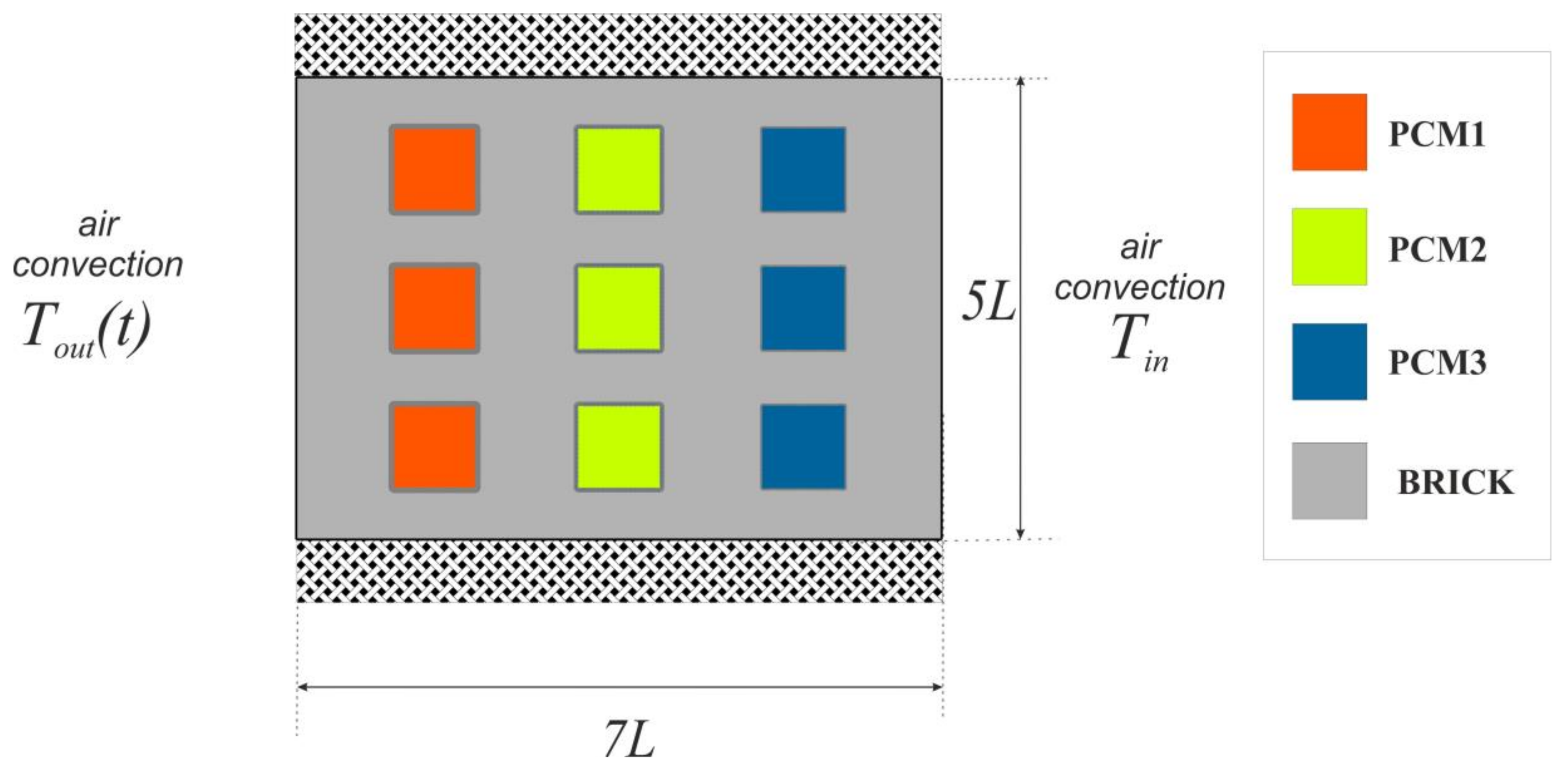
A two-dimensional problem of heat and mass transfer in a rectangular brick block, containing several inserts filled with materials with different melting temperatures, is considered (see
Figure 1). The horizontal walls of the block are thermally insulated. On the vertical boundaries of the region, the condition of air convection with constant heat-transfer coefficients,
γout at the outdoor surface and
γin at the indoor surface, is considered. The temperature of the medium on the left side,
Tout, varies according to the harmonic law, whereas the temperature of the medium on the right side is constant,
Tin. The following assumptions and constraints have also been adopted:
- -
thermophysical properties of materials do not change within one phase;
- -
the change in the volume of the material related to the phase transition is assumed to be negligible;
- -
the melt is considered to be a viscous incompressible liquid that satisfies the Boussinesq condition;
- -
the movement of the melt as a result of the occurrence of convective heat transfer is considered to be laminar.
Inside the brick, the heat transfer is carried out due to pure-heat conduction, so the energy equation will have the form [
34,
35,
36]:
Similarly, within the solid PCM, the following equation is used [
34,
35,
36]
The heat-transfer equations in the melt, taking into account the natural convection with primitive variables such as velocity, pressure and temperature for each PCM layer using the Boussinesq approach, are written as [
34,
35,
36]:
At the interface, the condition is valid; it determines the velocity of the movement of the interface along the heat flux in the normal direction to the interface, where is the normal unit to the interphase and Vn is the velocity of moved border along the normal unit. This approach, together with the governing Equations (2)–(6), requires determining the position of the interface at each time level and solving separate equations for solid and liquid phases.
Recently, to simplify the technique for solving the phase transitions problems, an approach using the concept of liquid fraction φ is often used [
34,
35,
36]:
This function is used further for a smooth transition of thermophysical parameters from one phase state to another. Thus, the effective thermal conductivity and volumetric heat capacity will be determined by the relations [
34,
35,
36]:
The energy equation for each material will take the form [
34,
35,
36]:
Here, subscripts i = 1,2,3, denote PCM1, PCM2 and PCM3, respectively.
Equation (8) is written in a non-dimensional form and it is solved in the entire region filled with phase-change materials. The transition from sensible heat to latent heat is also described using a smoothing function, where the Stefan number characterizes the ratio of latent heat to sensible heat.
The energy equation for the brick will take the form [
34,
35,
36]
Reduction to a dimensionless form was carried out using the following scales:
,
,
,
,
,
, where
is the velocity scale, and the temperature scale, Δ
T, was set on the basis of external temperature conditions and was equal to half the amplitude. The equations of fluid flow in the melt were formulated using the non-dimensional, non-primitive variables, such as the stream function Ψ
and vorticity
; the scales of which were determined from the ratios
and
, respectively. In the final view, the fluid flow equations are [
34,
35,
36]:
In Equations (8)–(11) the dimensionless complexes defining aspects of heat and mass transfer are: the Rayleigh number , the Prandtl number , the Stefan number , and Biot number . All selected scales of quantities and dimensionless complexes are determined by the properties of one material, provided by the subscript i = 1.
Initial and boundary conditions for the considered domain are explained as follows.
As initial conditions for t = 0 include a uniform temperature distribution in the brick Θ0 < 0 and zero velocity in PCM, from which it follows that Ψ = 0, Ω = −∇2Ψ.
The following are the set as internal and external boundary conditions:
- -
The condition of air convective heat exchange with the environment with a constant heat transfer coefficient αout and the external temperature, changes according to the harmonic law, when is set on the left wall. Here, Pτ
is the dimensionless time, in a dimensional form, corresponding to 24 h.
- -
Horizontal boundaries of the calculated domain are considered to be adiabatic.
- -
At the boundaries of cavities filled with phase-change material, perfect thermal contact conditions are set, such as , while for the velocity at the boundaries, the no-slip condition is provided, including Ψ = 0, Ω = −∇2Ψ.
- -
At the interface (at Θ = Θm), the no-slip condition is also set, including Ψ = 0, Ω = −∇2Ψ.
3. Solution Technique
Equations (8)–(11) have been worked out numerically by the finite difference technique [
34,
35,
36,
37]. The time derivatives have been discretized with the first order of accuracy, and the diffusion terms have been discretized by central schemes of the second order of accuracy:
The solution of the system of algebraic equations derived from the differential equations of parabolic type, namely, the energy Equations (8) and (9) and the vorticity Equation (11), has been obtained using the locally one-dimensional Samarskii scheme [
38]. The convective terms have been discretized by the Samarskii monotonic difference scheme with the second order of accuracy. The one-dimensional discretized equation, for the vorticity on the intermediate layer, has the form [
29,
34,
35,
36,
37,
38]:
The solution of the resulting system of linear algebraic equations has been carried out by the tridiagonal matrix algorithm. Discrete equation for the stream Function (10) has been worked out using the successive over relaxation technique. The order of approximation by the difference scheme of the original differential problem is O(Δτ + hx2 + hy2).
As a test problem, numerical simulation of the melting of gallium inside a rectangular region, heated by an isothermal side wall, has been carried out. The benchmark has been developed by Gau and Viskanta [
39].
Figure 2a shows a comparison of the velocity field with the numerical data [
40], and
Figure 2b compares the position of the melting front with the experimental data [
39] and the numerical results obtained by Kumar et al. [
41]. The experimental cavity has dimensions 8.89 cm in height, 6.35 cm in width, and 3.81 cm in depth; considering the low value of the Prandtl number, the influence of the flow structure is significant, therefore, the effect of friction on the side walls of the parallelepiped in the three-dimensional model appears on the movement of the melting front. As for the comparison with the numerical results of two-dimensional modeling, the solution obtained using the proposed algorithm is in good agreement with the solutions on the moving grid [
40] and the fixed grid [
41].
The algorithm has been also validated using the problem of lauric acid melting in a cavity heated by an aluminum slab. In an experimental study [
42], the influence of the heat-sink inclination angle on the convective-melting regimes has been studied.
Figure 3 shows a comparison of the results of the experiment [
42], numerical data [
43] and the present numerical solution for the phase-change line location with an inclination angle of π/2 at time of
t = 50 min. The maximum deviation of the interfaces is observed in the upper part of the cavity, where the heated melt accumulates. At the top wall for
y = 12 cm, the absolute error along the
X axis is 3.5 mm or 8%, while in the half-height of the cavity,
y = 6 cm, the absolute and relative errors are 0.18 mm and 2%, respectively. In the numerical study [
43], the heat-conducting walls have not been taken into account, so the melting process at the bottom is very slow. Considering the friction and heat conduction from the side transparent walls in the experiment, the obtained isotherms are in good agreement with the experimental data.
To obtain the most accurate results, the most optimal grid has been determined in terms of the accuracy of the results and the time spent on calculations. Solutions for the multi-PCM case for
L = 0.01 m, for three different grids with different time steps and parameters η, have been obtained. An important point in a grid choosing is the fact that a decrease in the spatial step requires a decrease in the time step. In this regard, the use of detailed grids significantly increases the time spent on modeling processes. So, the solution of the problem on the grid of 113 × 81 elements up to the time of
t = 6 h was completed in almost 14 h; for the grid of 141 × 101 elements, the calculation time is more than 55 h; and for the grid of 281 × 201 elements, the time of 234 h was already spent, that is, almost 10 days. The influence of the grid parameters and the time step on the average temperature of the right boundary and the temperature distribution at the time of
t = 6 h, is shown in
Figure 4. At the time of
t = 6 h, the maximum difference between the graphs is 0.046 degrees, while between the graphs obtained on the grids of 141 × 101 elements and 281 × 201 elements, the difference is 0.0001 degrees (see
Figure 4a). The isotherms obtained using these grids are coincided practically. All further calculations were carried out using the grid of 141 × 101 and 211 × 151 elements.
4. Results and Discussion
Since the phase-change materials have low thermal conductivity coefficients, lower than those of bricks, even in the absence of phase transitions, PCMs improve its thermal insulation qualities.
Table 1 presents the thermophysical properties of all components of the considered domain. The brick block size was considered equal to 7 cm × 5 cm and 14 cm × 10 cm. The temperature difference varies from 10 degrees to 25 degrees Celsius. Different melting temperatures of materials also make it possible to evaluate the influence of the relative arrangement of materials in the system, since the sequence of melting significantly determines the distribution of heat in the volume.
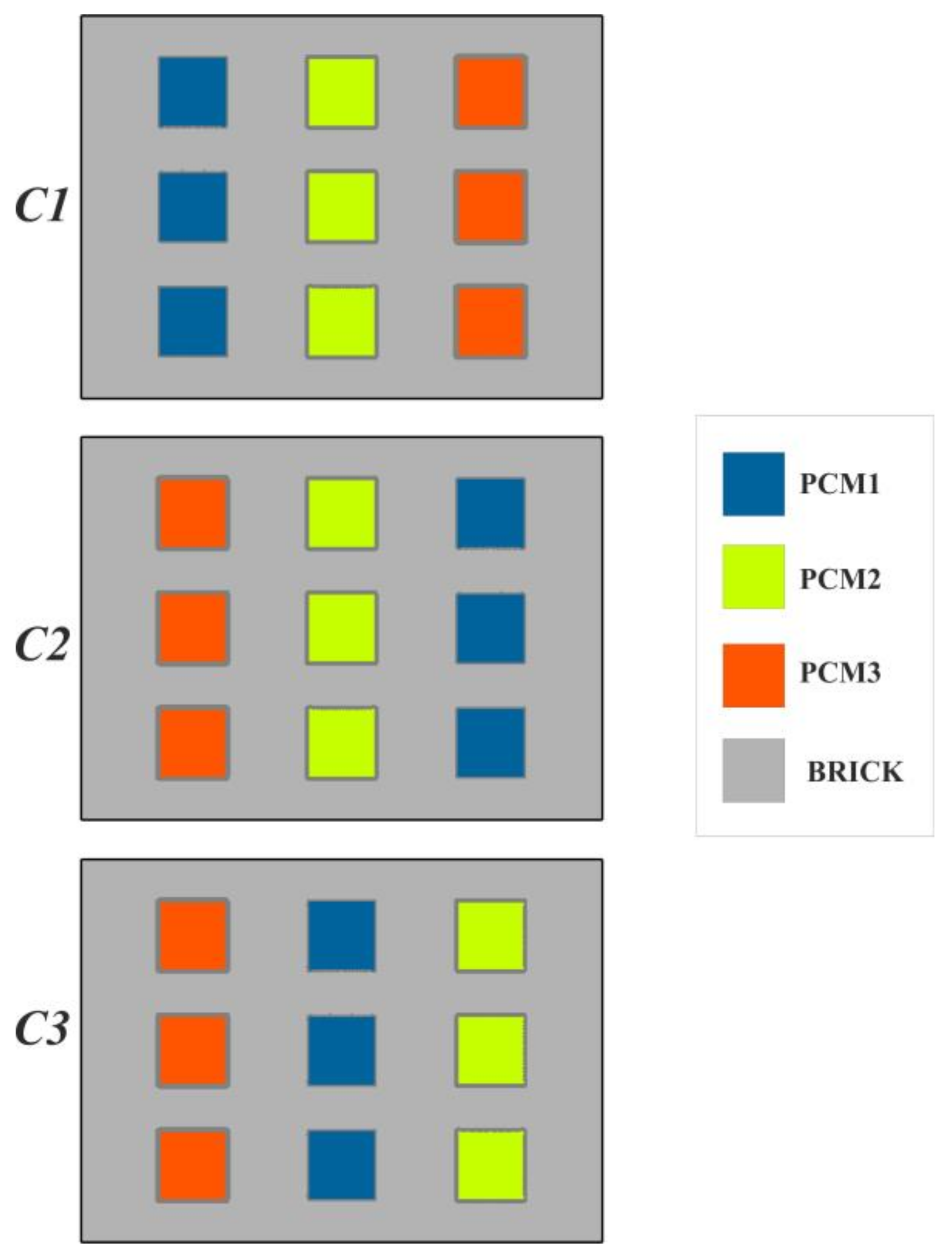
Figure 5 shows the main block configurations determined by the distribution of materials relative to indoor and outdoor, and are labeled as C1, C2 and C3. In addition to these models, the results for single-PCM bricks were also shown for comparative analysis.
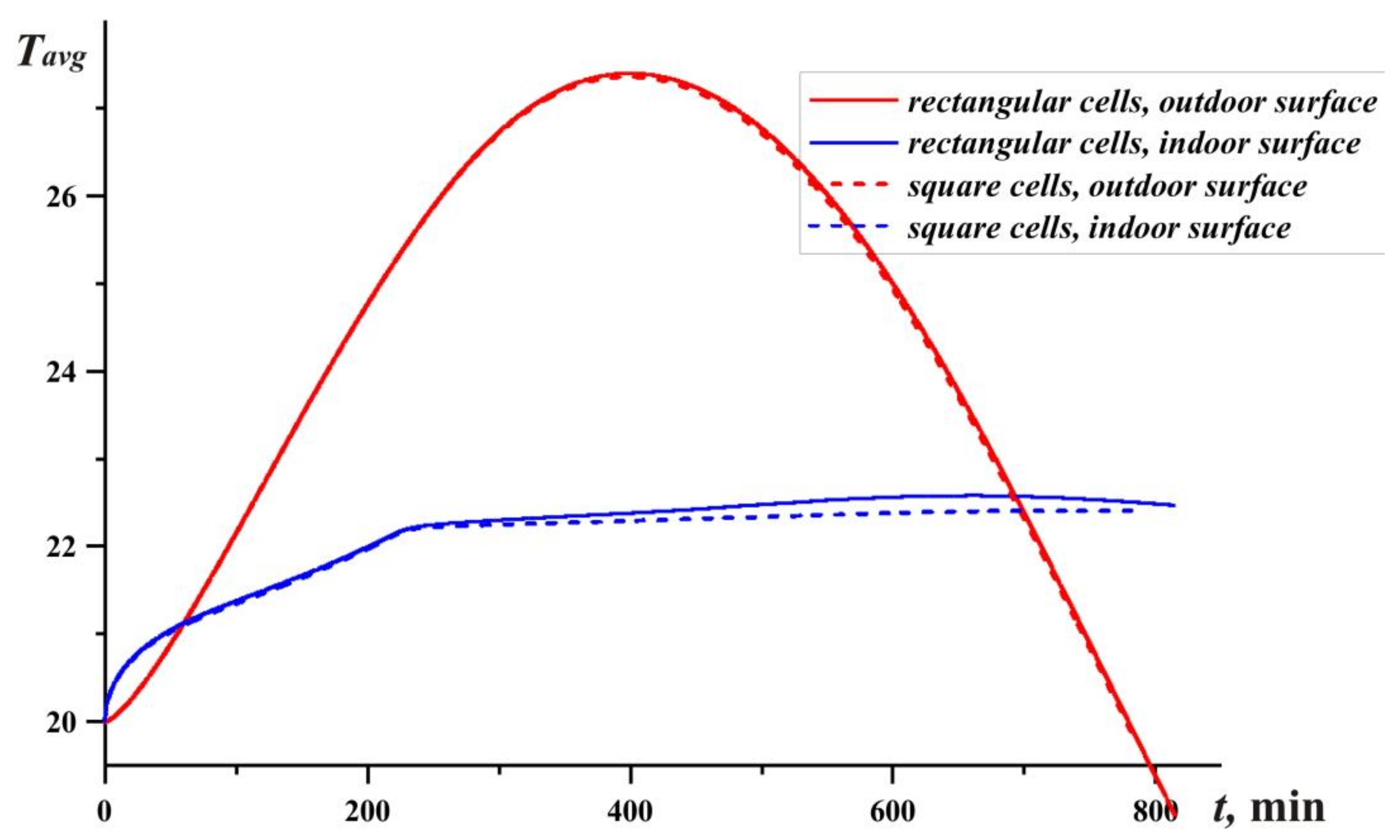
First of all, it is worth evaluating the effect of natural convection on the process of heat transfer in the system.
Figure 6 shows a comparison of plots for average temperatures at the lateral boundaries in the case of vertical PCM cells and evenly spaced square cavities. In the case of square cells, the surface area of the containers increases and the process of heat transfer between paraffin and brick is intensified. Thus, a slightly lower temperature is observed at the right-indoor boundary than in the case of high cavities.
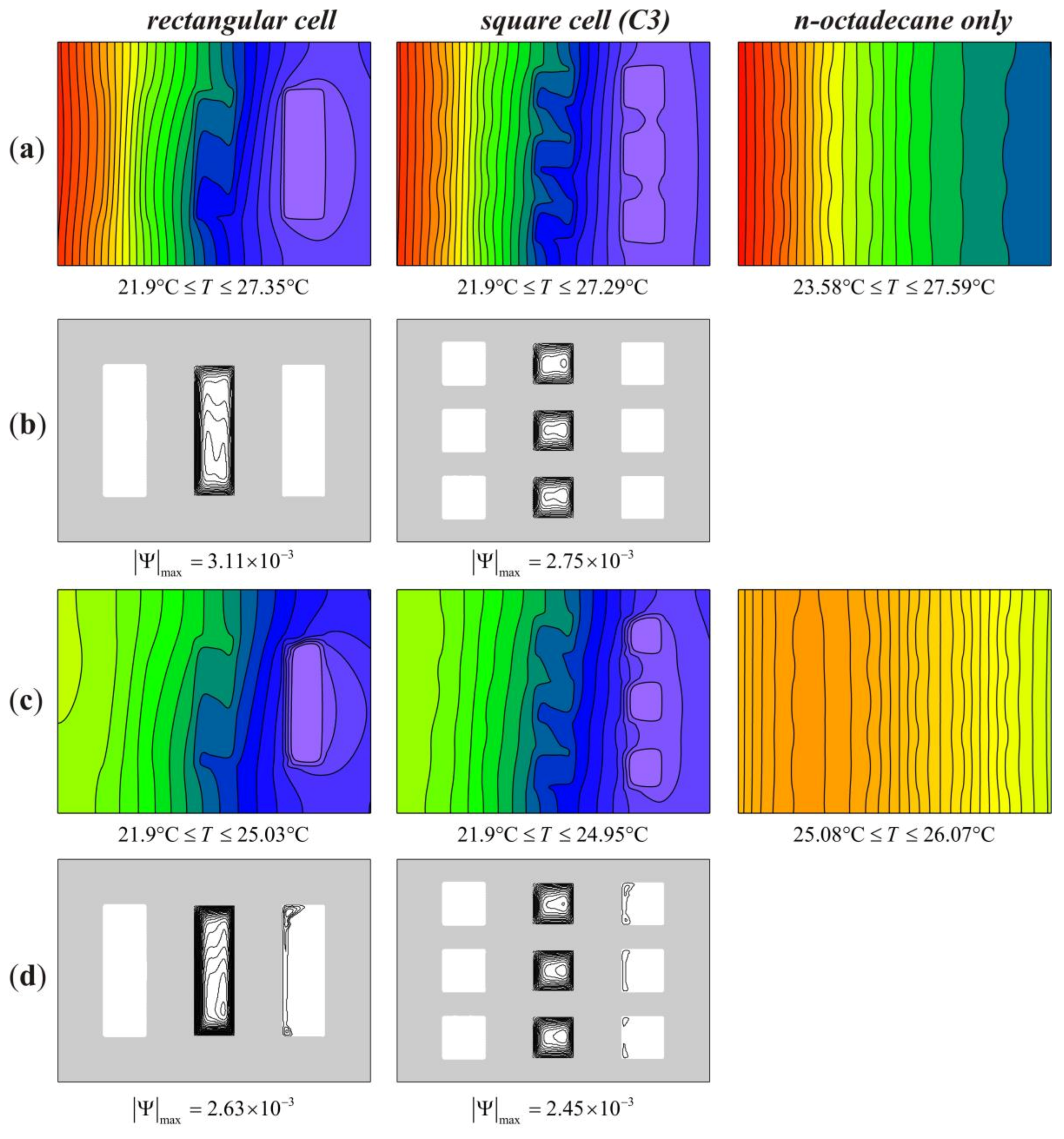
Figure 7 details the temperature fields and streamlines in PCM enclosures under ambient temperature conditions defined by the function
. Of the cases presented, melting occurs in C3 configurations with square and rectangular cells. In the case of single–PCM brick, where all the cavities are filled with n-octadecane, the paraffin remains in a solid state throughout the cycle. In this regard, the brick warms up faster than in multi-PCM brick, so the observed minimum temperature is higher by 1.68 °C at the time of
t = 6 h and by 3.18 °C at the time of
t = 10 h. Thus, in the model without phase transitions, a higher temperature is observed everywhere. In multi–PCM bricks, the middle layer of PCM, namely RT18, was in the liquid state at the initial time.
The material with the higher melting point, namely RT22, began to melt 3 h 40 min after the start of heating. At the time of t = 6 h, the largest temperature gradient is observed in the left part of the brick to the middle PCM inserts, since heating occurs from the left boundary. Convective vortices are formed in the melt, so the upper part of the region heats up faster. It should be noted that with an increase in the number of cells, the maximum values of the stream function decrease slightly by 11.5% at t = 6 h and by 7% at t = 10 h, however, the number of convective cells increases by three times, and the surface area increases by 50%. In this regard, RT22 melts faster in the case of square cells, and lower temperatures are also observed on the indoor surface.
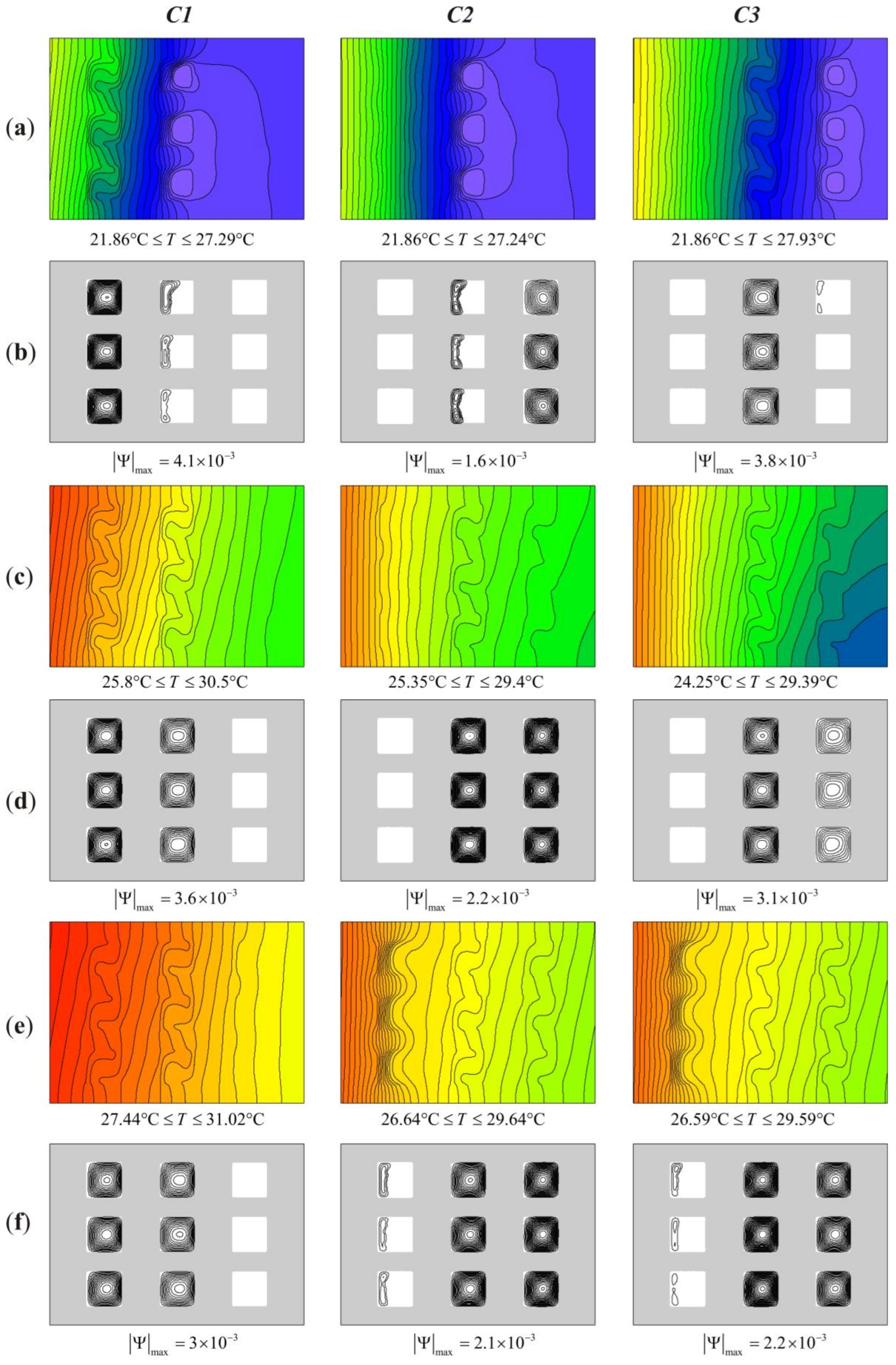
The order of the materials with different melting points is arranged in a multi-PCM system defining the effect of external temperature on it. The most logical case seems to be the internal arrangement of the material with a melting point close to the temperature maintained in the room. Therefore, a qualitative comparison of models with different PCM arrangement depending on the external conditions and the size of the brick block have been carried out. In the considered models, the layer order was as follows: C1 (RT18, RT22, n-octadecane), C2 (n-octadecane, RT22, RT18) and C3 (n-octadecane, RT18, RT22).
Figure 8 presents the temperature distributions and isolines of the stream function for a block of 10 cm × 14 cm with a temperature increase of 15 degrees in 6 h. The largest temperature difference in the domain is observed at peak external temperatures and amounts to 8.36 °C. The maximum values of the stream function
will be observed where the most melted material is closer to the outdoor. Therefore, at times
t = 6 h and
t = 8 h, the largest value
is observed in the case of C1. In bricks C1 and C2, RT22 takes the middle position and melts almost throughout the entire time period.
The melting process absorbs a significant amount of sensible heat; as a result of that, large temperature drops are observed on the left side and the isotherms are densely arranged, while on the right side, the temperature field is almost uniform and there is a slight heating from the indoor surface. If the material with a melting point
Tm = 22 °C is closer to the room, the heat wave is stretched, but the PCM melts more slowly than in the previous cases. It should be noted that the minimum temperatures noted in the distributions are always observed in the melting regions of the material and they are close to the melting point of a provided PCM, therefore in all cases and at different times, almost the same temperatures
Tmin are observed. Comparison of C1 with other models shows that the presence of natural convection in cavities located close to the outer surface significantly reduces the temperature of this surface, thereby increasing the heat exchange with the outdoor and accelerating the melting process in neighboring cells, can be seen from
Figure 8a,c. Thus, even without taking into account phase transitions, natural convection plays a significant role in heat-transfer processes in such systems.
After 6 h of heating, the ambient temperature begins to decrease, but the melting process continues for a long time, including the moment when the brick begins to cool from the outside. At the time of t = 12 h, the material with an average melting point practically melted in the case of C1, when heat transfer in neighboring cells is carried out due to natural convection. There is also the horizontal temperature stratification in the area on the right side; this is due to the fact that the PCM has already melted in the upper cell and the heat wave from the room spreads unhindered, while in the lower part, a small volume of RT22 still maintains a temperature close to 22 °C. Due to the fact that the ambient temperature is dropped to 20 °C, and the unmelted RT22 material was still in the area, the temperature distribution is in a small range. So, for cases C1 and C2, the maximum temperature difference does not exceed 1.71 °C. In this case, the minimum temperature for all configurations practically coincides with the phase transition temperature. In the case of C3, when the RT22 material is closer to indoor, the melting rate is lower than in other configurations, while sensible heat remains on the left side of the block and the maximum temperature is 1.1 °C higher, compared to C1.
From
Figure 9, it can be seen that an increase in ambient temperature, even by 10 degrees, shows a significant difference in the efficiency of models C1, C2 and C3. As noted earlier, the lowest temperature of the outdoor surface shows the C1 configuration due to natural convection near the boundary; the temperature difference reaches 0.79 degrees, compared to C3. Also in configuration C1, the highest temperature of the inner surface is noted to be slightly higher than C2. From a cooling point of view, the most effective is the arrangement of materials when RT22 is closer to the room, the advantage being, in this case, the surface temperature was 0.61 degrees, and at the same time, higher temperatures of the outdoor surface are observed in this model, therefore, this is the least intensive heat exchange with the environment and the smallest amount of accumulated thermal energy.
Considering the case
L = 0.01 with a smaller PCM volume, cavities have a lower height and the effect of natural convection is reduced. At high-thermal loads, the RT22 paraffin has time to melt and the temperature of the brick rises to the melting temperature of n-octadecane. As in the previous case, configuration C3 shows a slower melting of RT22 and a more intense heating of the outer part in the first 4 h (see
Figure 10a). However, by the time
t = 6 h, corresponding to the maximum ambient temperatures, all cells with RT22 are completely filled with melt and the temperature in the brick rises sharply.
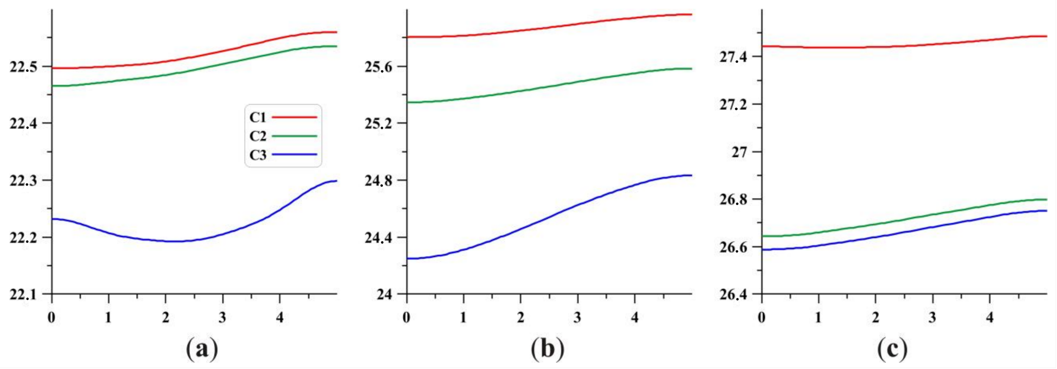
Figure 11 shows the graphs of the average temperature distribution on the left and right borders of the brick. The graphs show the beginning and the end of the melting process of the RT22 material. They are reflected in the temperature output to constant values after 2 h and the temperature increases after 5 h, respectively. It should be noted that the lowest temperatures during the melting of RT22 have been observed when this material is closer to the room. Thus, at 4 h, the average temperature of the inner surface is 0.3 °C lower for model C3, while for C1 and C2 they are almost the same. As for the outer surface, the average temperature of this boundary is higher in the C3 brick model, as in the case of
L = 0.02 m (see
Figure 11).
After RT22 is completely melted, the temperature in the domain begins to rise sharply. Since in the C3 arrangement, there is a delay in the melting of RT22, the temperature in the block starts to rise later than in C1 and C2, and at the time of
t = 6 h, the difference in the average indoor temperatures reaches 1.34 degrees, and the melt delay time is only 6.5 min. With a further increase in temperature in the brick, n-octadecane begins to melt. It should be noted that a phase-change material with a high-melting point, such as n-octadecane, located in the inner layer of the structure close to the room, will be productive only under long-term and high-thermal loads. Thus, model C1 (see
Figure 10e), at the time of
t = 8 h with the placement of n-octadecane near the inner surface, warmed up 1.4°degrees more than the others, and the melting process did not start at the same time; the heat exchange with the indoor air is improved because the difference in the minimum temperatures of the computational area reaches 0.85 °C. In the cases of C2 and C3, n-octadecane starts to melt earlier and its close location to the outdoor surface prevents the right side of the brick from heating. In these cases, lower temperature drops are observed and the graphs of average temperatures
Tin begin to converge with each other. At the same time, the difference in average temperatures on the right border reaches 0.7 degrees, relative to the difference with the air temperature in the room, resulting in a 20% difference.
Figure 12 shows the temperature profiles on the right surface of the block located in the room. Throughout the entire heating process, the temperature values at the right boundary for C1 remain maximum. At the same time, the increase in temperature along the height is insignificant, since at the presented time points, the one closest to the PCM boundary is n-octadecane, which remains in a solid state. In containers filled with melt, convective vortices arise, which by raising the heating liquid, warm the upper part of the brick. The most noticeable effect of buoyancy forces on the temperature of the inner surface wall is observed in the C3 configuration, where the temperature profile in this case is the most curved. At peak ambient temperatures, at the time of
t = 6 h, the temperature difference along the height is 0.58 degrees (see
Figure 12b).
With large temperature differences during the day, the melting process can cover all phase-change materials, and three-stage melting imposes its own peculiarities on the processes of heat and mass transfer in the system. The order of materials melting, and their relevance to each other’s location, requires an integrated approach to the study of the problem. In the previous cases, the melting of RT22 and n-octadecane was considered, while RT18 was in the liquid phase from the very beginning. With sufficient volumes of PCM and large temperature differences, the greatest thermal load will be experienced by materials located in the outer layers of the building envelope. Under conditions of a sharp temperature increase, the influence of the material’s location becomes more significant. From the point of view of room temperature maintenance, configurations C1 and C3 show the best temperatures, since the temperature of the right wall is closer to the temperature maintained in the room (see
Figure 13). In configuration C2, the wall temperature is close to the melting point of RT18, and reached a maximum external temperature at the time of
t = 6 h, whereas
Tavg on the right wall is 18.94 °C, which is 1.46 degrees lower than in case C1, at the time of
t = 12 h. As can be seen by these results, the difference is already 2.94 degrees. Since the temperature difference between the wall and the room is directly proportional to the intensity of heat transfer, it should be noted that in configuration C2, at the time of
t = 6 h, the heat transfer is 40.5% higher, and at the time of
t = 12 h, the heat transfer is 207% higher, compared to C1.
Thus, in terms of efficiency, the choice of phase-change material should be based on the temperatures maintained inside the building. A significant degradation of heat transfer is observed when the phase transition temperature approaches the room temperature. However, the use of additional PCMs with different melting points expands the range of using of such a system, since weather conditions change with the season, and the ambient temperature does not always fluctuate around a one-fixed point, Tm, and the duration of hot or cold weather can exceed days and weeks.


