1. Introduction
Rock dumps in mining regions create environmental problems. They cover large areas which could be used for the development of housing systems and agricultural lands. The extraction of waste rock from mines is extremely expensive, which increases the production costs. These two problems can be solved by filling the open area of mines with the waste rock, which is sufficiently relevant for underground mining [
1]. Rock filling requires the fragmentation of the mined rocks for further pneumatic or hydraulic transportation to the open area. In this case, the fact that solid rocks, having an ultimate strength of up to 180 MPa, are to be subjected to crushing must be considered in detail. It is advisable to prepare the rock for transportation and direct filling of the mine. The location of the crusher in a mine imposes a number of requirements on its design and parameters; primarily they are related to overall dimensions and explosion safety issues. One of the promising options is using single-roll gyratory crushers [
2].
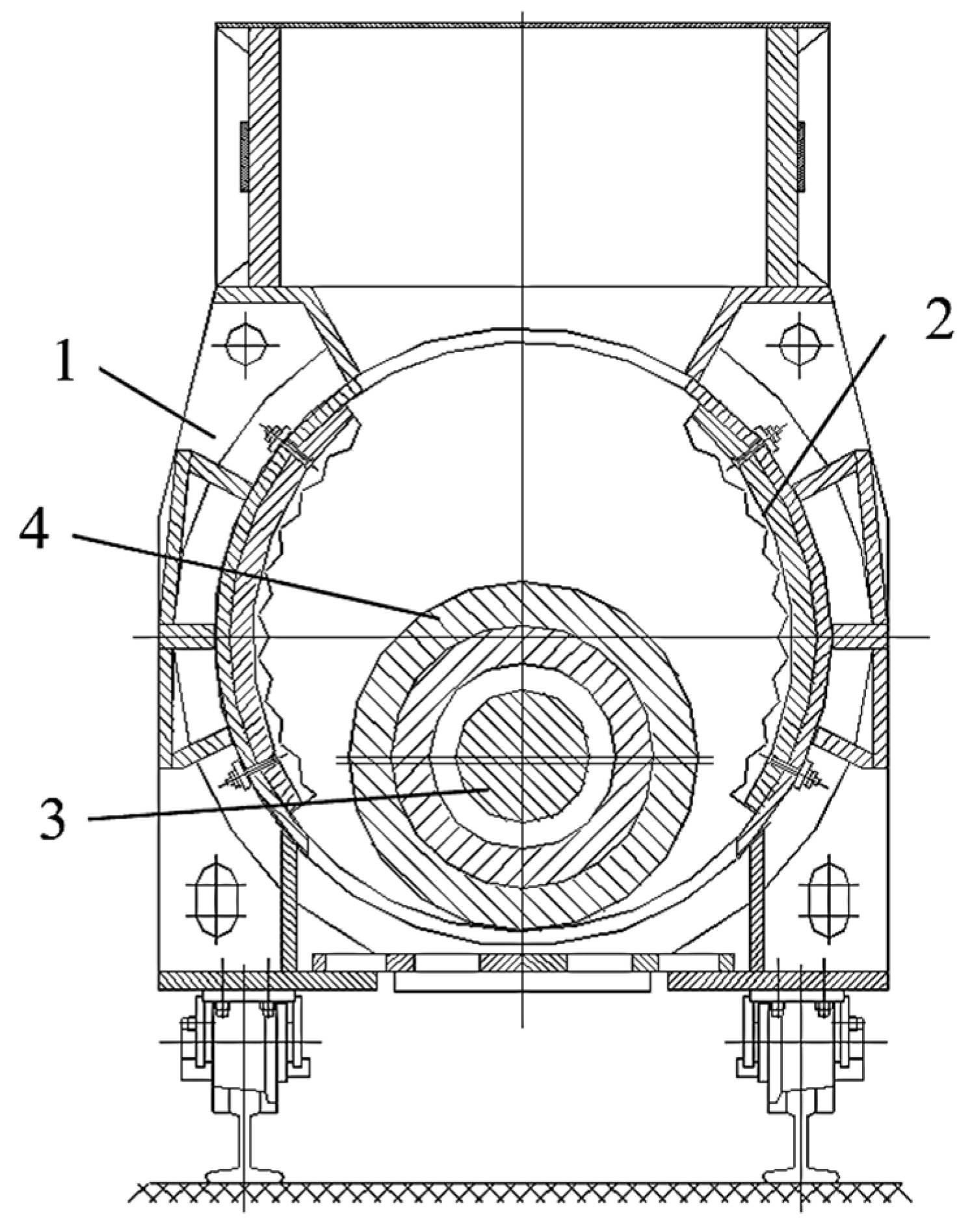
Figure 1 shows a cross section of the working chamber of such a crusher.
Crushing is performed, splitting the material by jamming the rock pieces between the roll and the fixed jaws. The crusher shaft is equipped with counterweights that balance inertial forces caused by the eccentric arrangement of the roll. The crusher has two symmetrical working chambers to the left and right of the roll, which provide high productivity in the presence of small dimensions, and can be used for crushing solid rocks. Due to such small overall dimensions, crushers of this type can also be used in mobile crushing units that are located on the ground.
To create high-performance single-roll gyration crushers, it is necessary to solve the issues concerning the justification and selection of the parameters of the working chamber and the actuator. This may improve the productivity and reduce the power consumption of the crusher [
3]. There are a number of research works that are devoted to the study of, and optimization of, crushing equipment. Article [
4] describes the optimization of the operating mode parameters of the jaw crusher. A mathematical model of the crushing process was developed. Its use facilitated the achievement of maximization of productivity and of the crushing degree. The optimized parameters are a stroke travel value, an inclination angle of the jaw, a swing frequency of the crusher moving part, and a relieve slot size. In this case, the method of undetermined multipliers (Lagrangian method) was used. Despite these attributes, the resulting mathematical models cannot be directly used in setting and solving the task for optimizing a single-roll gyration crusher. The works [
5,
6] show the mathematical modeling of high-pressure twin-roll crushers. These papers present a model based on Johanson’s theory established for roller compactors, and considered all the delays. The non-linearity or delays were handled using Matlab software version 6.1 (MathWorks, Inc., Natick, MA, USA). However, the results of these studies cannot be applied to gyratory crushers. Furthermore, the above works did not address the issue of optimizing the modes or parameters. The work in [
7] studied the working process of a single-roll crusher used for crushing rocks. The article presents analytical studies of the forces acting on a piece of rock. The problems of optimizing the parameters of the crusher are not considered. The crusher considered had a fixed roll axis, i.e., it was not gyratory. The study in [
8] demonstrates the mathematical models of two-roll crusher dynamics. The formation of the peak loads on the rolls was investigated. However, the study did not provide recommendations on the selection of parameters for the working chambers and actuators. Works [
9,
10] provide recommendations for the design and manufacture of crushers for aluminum cans, which cannot be directly applied to rock crushers. The work in [
11] proposes the design of a continuous crusher, but there is no mathematical model of its operation. At the same time, this crusher is not a type of single-roll gyratory crusher. Article [
12] discusses the issues of optimizing the eccentricity of the drive shaft in relation to jaw crushers in order to improve reliability. The optimization was performed based on the data obtained from the operation of such crushers in various pits. Notwithstanding the foregoing, these data cannot be used to solve the problem of optimizing the shaft eccentricity of a single-roll crusher. The study in [
13] presents the results of the experimental research of a crusher designed for stone crushing in the construction industry. Article [
14] studies rock fragmentation in cone crushers and the effect on particle size distribution and mechanical properties of the crushed product. The work in [
15] studies the effect of the type of crusher on the shape and dimensions of the crushed product. Yet, there are no recommendations on selecting a crusher type to prepare the filling material to be used in coal mines and pits. The paper in [
16] simulates and optimizes the shape and size of the crushed product for cone crushers and vertical shaft impact crushers. Mathematical models are used to study the influence of the operating parameters on the productivity and quality of the grinding product. However, these models cannot be used for the optimal designing of single-roll gyration crushers having a horizontal axis in the roll rotation. The work in [
17] considered aspects of the automatic control of mobile crushing and sorting units equipped with cone crushers. The research in [
18] is devoted to establishing the relationship between various properties of solid rocks and their properties in regard to being crushed and ground. The paper in [
19] studies cone crusher performance using the discrete element method (DEM) involving noncircular particles. The behavior of rock particles in various areas of the working chamber was simulated. However, the article did not address the problems of the optimal design for such crushers. The works [
20,
21] dwell on the same method, along with the method of genetic algorithms, to optimize the process of crushing iron ore in a cone gyratory crusher. A prediction model of the crushing chamber performance was established through multiple nonlinear regression, and multi-objective optimization was performed, based on the genetic algorithm. The design of a single-roll crusher differs significantly from a cone crusher, so the results of these studies cannot be directly used.
The mathematical modeling and optimization of the parameters and working processes of a cone crusher were addressed in [
22,
23]. A mathematical model of the working process of a jaw crusher was developed in [
24], which was used to predict the energy consumption of such machines. In [
25], the working process of hammer crushers was optimized using the method of DEM discrete elements. The authors of [
26,
27] conducted important studies on the calibration and verification of the cone crusher model. They formulated the calibration problem as an optimization problem based on the least square method. The low values of the objective function, found by the authors, showed that the calibrated model exactly corresponded to the verification data set. The authors’ methodology allowed the model to be calibrated based on the data available during the industrial operation. The problems of modeling and controlling the cone crushers were considered in detail in [
28].
The results of works [
20,
21,
22,
23,
24,
25,
26,
27,
28] are extremely important, and the authors achieved good results. Nevertheless, they cannot be directly used to model and optimize the parameters of a single-roll gyratory crusher. Such a crusher differs significantly from cone, jaw and hammer crushers in design and in the operation principle.
The analysis of the published works shows that addressing the issues of the mathematical modeling and optimization of crushers is essential. The rational profiling of the working chamber of a single-roll gyratory crusher, as well as the selection of rational values of the eccentricity and rotation speed of the crushing roll shaft, play vital roles in effective crushing. However, there are no mathematical models in the technical literature that solve the problems of rational profiling of the working chamber and optimizing of the parameters of single-roll gyratory crushers in relation to the processes of preparing the rock to fill open areas of mines.
Hence, research aimed at the mathematical modeling and optimization of the parameters of jaw, cone, hammer, two-roll and single-roll crushers is, currently, being widely conducted. On the other hand, similar studies of promising single-roll gyratory crushers for crushing strong rocks in mines have not, yet, been performed.
The purpose of the study was the mathematical modeling and optimization of the working chamber and the actuator (roll) of a single-roll gyratory crusher designed for crushing solid rocks during their preparation for the filling of open area of mines.
Consequently, the aims were as follow aims:
to obtain and solve the differential equation of the curve of the rational profile of the working chamber jaw of a single-roll gyratory crusher;
to obtain analytical expressions for determining the speed and capacity of the considered type of the crusher;
to develop an analytical mathematical model for determining the kinematic components of the roll load of a single-roll gyratory crusher;
to optimize the parameters of the crusher working chamber.
This work consists of the first review part and three other parts.
Section 2 describes the methods of solving the set tasks.
Section 3 describes finding the equation of the profile curve of the crusher working chamber and analytical expressions for determining the crusher productivity and kinematic compounding loads acting on the working body. In this section, the task for optimizing the main parameters of the working chamber at the stage of designing the machine is set and solved. The main conclusions and results of the study are formulated in
Section 4.
2. Materials and Methods
The differential equation of the curve describing the rational profile of the working chamber jaw was derived and solved in the first stage of the study. The analytical expressions for the rational speed of the roll were then derived, including the crusher capacity. At the next stage, we developed a mathematical model to determine the kinematic load members acting on the working element. All the resulting analytical expressions represented a mathematical model of the operation of a single-roll gyratory crusher. Then, the problem of the multi-dimensional optimization of the parameters of the working body and the crushing chamber was set and solved in terms of the following: target functions, optimized parameters, and limitations. Consequently, a method to solve the problem of multi-criteria optimization was chosen.
Analytical methods were used in the study. Solid-state statistical methods and methods to compile and solve first-order ordinary differential equations were used to solve the problem of the rational profiling of the crusher-working chamber. The method of decomposing the periodic functions into Fourier series was used to analyze the periodic components of loads on the working roll.
The multi-criteria optimizations of the parameters of the working chamber and the roll were made using the fuzzy set method [
29,
30]. As to the multi-criteria optimization, the following three goal functions (quality criteria, optimization criteria) were selected: performance, a coefficient of the load moment variation, a coefficient of the radial force variation. Achieving the maximum performance increases machine efficiency. Minimizing the load variation coefficients allows reduction in the dynamics of loads and increases the reliability and durability of a crusher. The presence of three goal functions facilitated thinking about the multi-criteria nature of the optimization problem. The principle of the adopted method of the multi-criteria parameter optimization was as follows. The parameter space is equally filled with points according to the deterministic algorithm:
where
Ni—number of levels of the
i parameter;
j = 1, 2, …, Ni—sequence number of the value of the i parameter.
A computational experiment was performed for each point, as a result of which the values of the selected partial criteria (target functions) were determined, which formed the set K = {k1, k2, …, knc}, where nc was the number of partial criteria.
The best solution was then selected, based on the definition of the generalized criterion. The formation of a generalized criterion requires the normalization of particular criteria, i.e., making them dimensionless.
The criteria were normalized by representing them as a fuzzy set:
where
ξj (
kj)—membership function of a particular value of the
j criterion for the best fuzzy set.
The membership function takes values from the interval of [0, 1], and the closer the value is to 1, the higher the degree of compliance of the criterion having the “best” solution, i.e., the degree of approximation to the local optimum, according to the criterion kj.
For example, when the task is reduced to minimizing the criteria, it is advisable to present the membership function as follows:
where
kjB,
kjM—the largest and the smallest of the calculated values of the
j criterion, respectively;
αj—nonlinearity indicator that is selected by a person making the decision for heuristic reasons.
At αj = 1, the membership function is linear, at αj > 1 it is concave, at 0 < αj < 1 it becomes convex. Obviously, the more stringent the requirements are to the approach of the given criterion to the local minimum kjM, the larger the αj parameter should be.
The generalized criterion is also taken as a membership function:
where
ε—parameter selected subjectively, depending on the accepted principle of compromise.
The compromise solution is chosen considering the limitations based on the considered options of the combination of parameters in such a way as to provide the maximum value of the generalized criterion.
Therefore, the method of solid-state statics and the method of solving ordinary differential equations of the first order were chosen to solve the problem of the rational profiling of the crusher working chamber. The analysis of the periodic components of the loads acting on the working roll involved the method of decomposing the periodic functions into a Fourier series. Solving the problem of optimizing the parameters of the crusher working chamber required adopting a well-known method. The method adopted was based on the representation of partial and generalized criteria (goal functions) in the form of membership functions of a fuzzy (blurred) set. The combination of the applied methods achieved the goal of this work.
3. Results and Discussion
One of the main tasks in designing a single-roll gyratory crusher is to choose the shape and size of the working chamber. When determining the rational profile of the jaw, the main requirement is the ability to capture a piece of rock having a maximum size
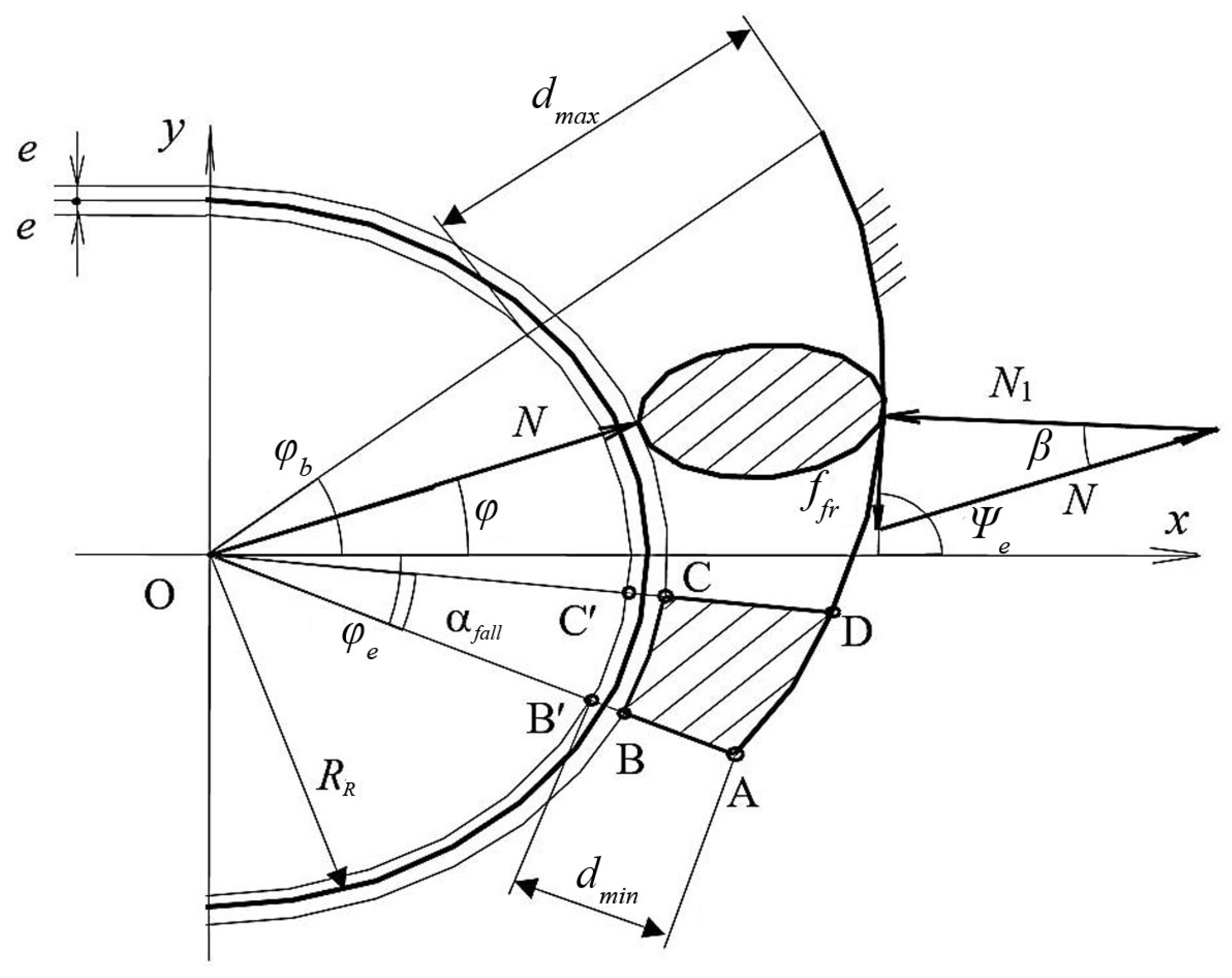
dmax (approximately 300 mm for mine crushers), and keeping the piece during crushing in the crusher chamber. It is necessary to devise a calculation scheme to obtain the equations of the curve of the rational form of the jaw. This diagram should show the forces acting on a piece of rock in the crushing chamber on the parts of the roll and jaw. Choosing a rational shape for the jaw profile allows the equilibrium of a piece of rock in the crushing chamber to be achieved. This ensures retention of the piece of rock in the chamber during its crushing. The diagram of the interaction of the piece of rock with the roll and the jaw is shown in
Figure 2, where
RR is the radius of the roll and
e is the eccentricity (
e << RR).
Let us consider the balance of the piece of rock in the crusher’s working chamber. The following forces act on a piece of rock:
N is the force acting on the side of the roll, which, in the first approximation, passes through the shaft axis (point O);
N1 is the normal component of the jaw reaction;
Ffr is the friction force of the piece against the jaw. Equilibrium is possible if the forces to be adjusted form a force triangle, as shown in
Figure 2. This triangle shows the following:
where
ffr—coefficient of the rock friction against the jaw,
β—angle of contact, i.e., the angle between the tangents to the surfaces of the roll and the jaw at the points of contact (at the recommended value of
ffr = 0.3
β = 16.4°).
The equation of the profile curve
y(
x) is determined by condition (5). The derivative
y′(
x) is the tangent of angle
Ψe to the desired profile, so, while
, let us present the following differential equation:
Solving this equation allows the formulation of an expression for the desired profile in the polar coordinate system:
where
rb =
RR +
dmax −
e.
The above Equation (7) shows that the required jaw profile is a logarithmic spiral. The establishing of this fact in our study is the first time it has been established. This fact makes it possible to optimally design the working chamber by setting the optimal value of the initial angle of the jaw. Analysis showed that a circular arc can approximate this curve with sufficient practical accuracy. It is possible to specify the value of the angle
φb considering the design or to treat it as one of the optimized parameters. Then, the value of the angle
φe is determined by the expression:
where
dmin—minimum size of the crushed product piece.
To solve the problem of optimizing the crusher parameters, a mathematical model was developed. That is, in this case, a set of analytical mathematical expressions were obtained which establish the relationship between the optimized parameters and the target functions (quality criteria). The optimized parameters are the eccentricity of the working roll and the initial angle of the working chamber jaw. Other parameters depend on the possible overall dimensions of the crusher (these are limited by the size of the working mine) and the properties of the decayed rocks. These parameters are set by the technical design assignment. One of the functions of the goal is crusher productivity. Until now, there has been no mathematical model for this type of crusher ands, therefore, its development is one of the important scientific results of our research.
The considered crusher was closest to the jaw crusher. Therefore, when selecting its parameters, we made use of experience in designing jaw crushers [
21]. Choosing a range of eccentricity values such that the dimensions of the “fall-out body” (ABCD in
Figure 2) roughly correspond to the required size of the piece of the crushed material (e.g., 70 … 80 mm permitted for mine crushers).
The pieces may fall out of the crusher if they are below the radial plane CD at the level at which the width of the crushing chamber at the end of the working stroke is equal to the width of the output slot at the maximum withdrawal of the working roll, i.e., CD = AB′. Based on this condition, using expression (7), we may find the angle
αfall determining the dimensions of the “fall-out body”:
The fall-out time of the ABCD body during its uniform acceleration is
where
Sc is the path DA of the movement of the particle located at point D,
ac is the acceleration of the particle moving along the DA profile under the influence of gravity and the pressure of the overlying rock pieces. The duration of the rotor withdrawal from the jaw is equal to the time of half of the shaft turn
, where
nsh is the shaft speed in rpm. Hence, using
tfall and
to, we can derive an expression to determine the required shaft speed:
When determining the acceleration of particle
ac, it is possible to take
ac = 0.5 (
ainc +
g), where
ainc is the acceleration of a particle moving under the influence of gravity, taking into account friction over the surface DA, which, in the first approximation, can be considered as an inclined plane, and
g is gravity acceleration:
where,
The volume efficiency of the crusher is determined by the expression:
where
φloos = 0.5 … 0.6—coefficient of material loosening at the exit from the crusher,
Vfall—volume of the “fall-out body”, m
3;
where
S1—area of Figure ABCD;
Lroll—roll length.
Based on the obtained dependencies (5 … 15), and using the eccentricity values e and the central angle of the beginning of the profile φb, it is possible to determine the capacity of the crusher.
The cyclic nature of the rock compression in the working chamber of the gyratory crusher leads to the formation of an uneven load on the roll. The amplitudes and variational coefficients of radial force oscillations, and the moment of resistance forces on the roll, depend, significantly, on the central angles of the profile beginning φb and end φe.
It is necessary to obtain analytical expressions for these dependencies to solve the problem of minimizing the load variation coefficients. A calculation scheme has been compiled to develop such a mathematical model, which determines the resulting radial forces and the moment of forces acting on the roll.
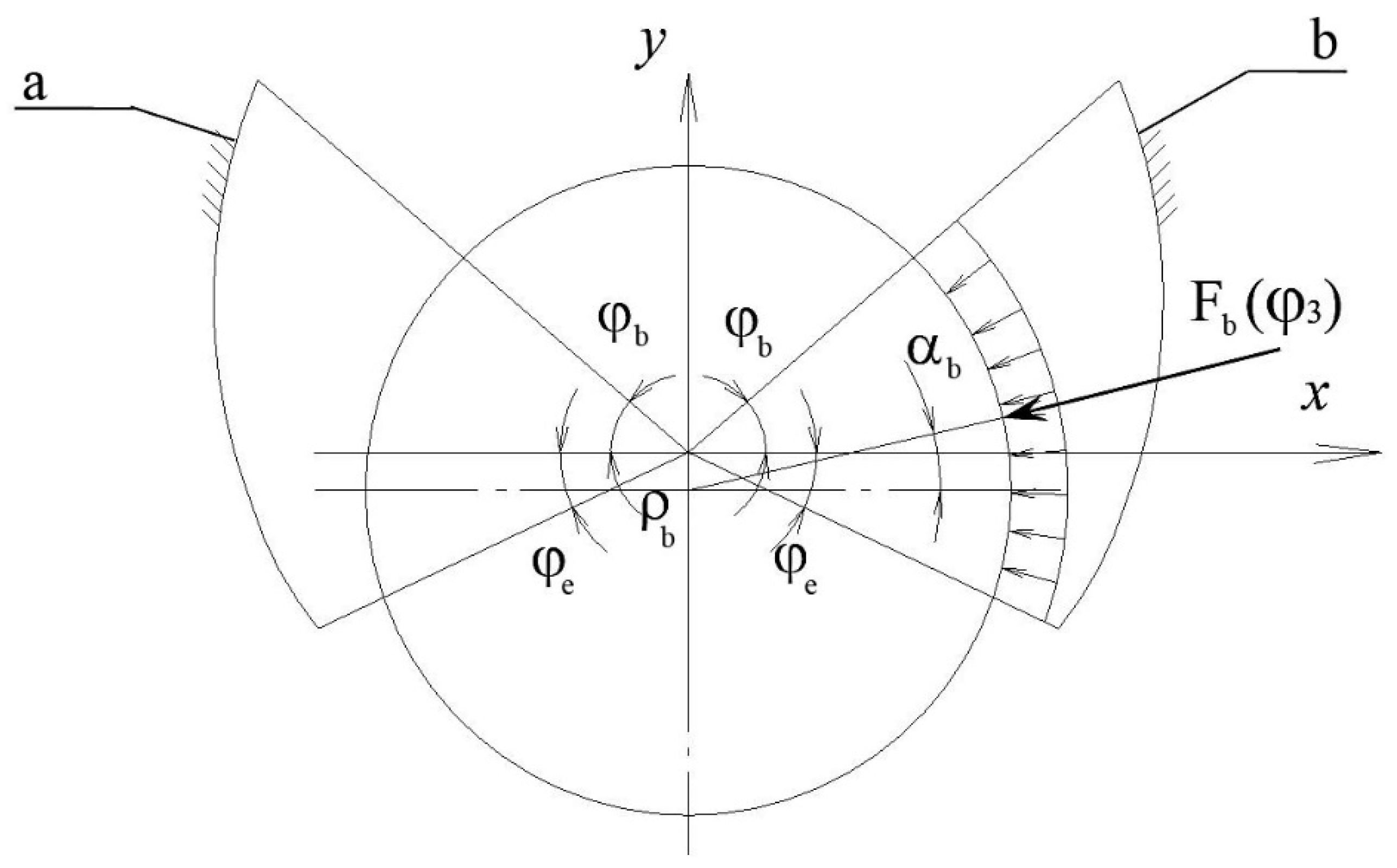
The design diagram for determining the kinematic components of the loads acting on the roll is shown in
Figure 3.
The positive direction is the counterclockwise direction of the rotation. Crusher jaws are marked as “a” and “b”. The angles are counted upward from the axis x, i.e., the angle φb shown in the figure has a positive value, and a negative value applies to angle φe.
The following assumptions were made for the design diagram:
- -
radial roll load for each of the jaws is proportional to the central angle of the sector in which the crushed rock mass is compressed;
- -
resulting radial force for each of the working jaws is applied in the middle of the sector in which compression occurs;
- -
the force line of action passes normal to the roll surface when determining the crushing force arm;
- -
the line of action of the force passes through the axis of rotation of the shaft when determining the inclination angle of the crushing force, so the error thus introduced is small, since the eccentricity e is significantly less than the radius of the roll RR.
The torque acting on the roll
MF =
Ma +
Mb, where
Ma,
Mb are moments of forces
a and
b acting on the side of the jaws, is:
Here,
Fa,
Fb are forces acting on the roll on the part of jaws
a and
b;
ρa,
ρb—arms of these forces acting relatively the shaft rotation axis:
where
αa,
αb are inclination angles of force vectors
Fa and
Fb to the horizontal axis
x (
Figure 3).
The projection of forces
Fa and
Fb on the coordinate axis is determined by the expression:
The resulting force on the roll and its projections are determined as follows:
Table 1 shows the expressions by which values
Fa,
Fb,
αa and
αb are determined as functions of the rotation angle of the shaft φ for the characteristic sections into which one shaft revolution is divided.
In
Table 1,
PF is the specific force acting on the roll relative to the single central angle:
where
Fmax—maximum force acting on the roll, which arises when the material is compressed over the entire surface of the jaw.
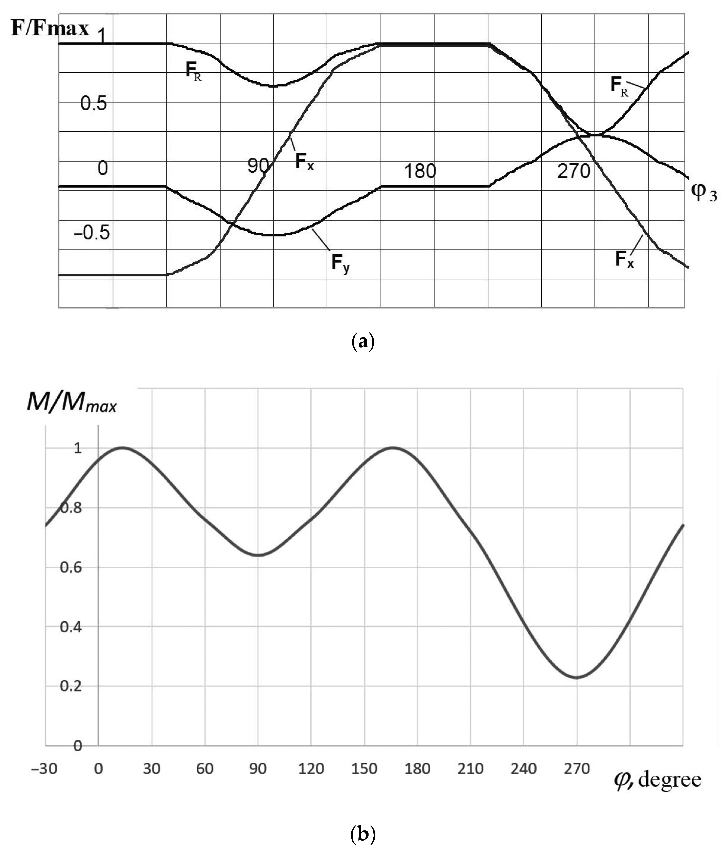
The dependence diagrams (16) and (20) for typical mine crusher parameters are shown in
Figure 4. The indicated diagrams are given in the dimensionless form, and the forces normalized by the value
Fmax (
Figure 4a), and by the value
Mmax =
Fmax e for the moments (
Figure 4b).
The above-mentioned results show that the kinematic components of the roll loads represent the periodic functions of the shaft rotation angle.
The resulting analytical dependencies represent a mathematical model combining the optimized parameters (eccentricity and the profile initial angle) with the target functions (variation coefficients of the load acting on the roll). Such a mathematical model for the crushers under consideration was obtained for the first time.
The periodic functions describing the external load are decomposed into a Fourier series to simplify the analysis:
where
i—ordinal number of the harmonic,
N2—number of the harmonics taken into account (the analysis shows that for a typical mine crusher it is possible to take
N2 = 4). The values of the coefficients
ai and
bi in relation to a typical mine crusher, where
φb = 60° and
φe = −34°, are given in
Table 2.
Table 2 shows that the kinematic components contain the 1st-, 2nd-, 3rd- and 4th- order harmonics, having significant amplitudes. This situation must be taken into account when analyzing the occurrence of resonant oscillations of the crusher drive and the body.
Hence, at this research stage, a sufficiently simple analytical mathematical model of a single-roll gyration crusher was obtained, which facilitated effective solving of the problem of choosing the optimal parameters of the working body. In the future, the model will be improved by taking into account the stochastic components of the crushing loads and dynamic processes in the crusher drive. This will improve accuracy in determining optimal parameters when designing crushers of a similar type.
The type of diagrams and the values of the coefficients ai and bi depend on the mutual position and size of the jaws, i.e., on the angles φb and φe. The task of selecting values of these angles and shaft eccentricity, at which the minimum amplitudes of the kinematic load components and the maximum capacity of the crusher would be achieved, is of great interest.
The task of optimizing the crusher parameters includes the selection and justification of target functions (quality criteria), optimized parameters, limitations and a method for finding optimal solutions. The design capacity of the crusher Q, which needs to be maximized, and the variation coefficients of torque and radial force νm and νF, which require minimization (k1, k2 and k3, respectively), are taken as the target functions. Therefore, the studied optimization problem is a multi-criteria problem.
It is advisable to take the values of the initial angle of profile
φb and the eccentricity
e (
P1 and
P2, respectively) as objective variables in the considered optimization problem. The parametric restrictions are imposed on the values of the optimized parameters in terms of the possibility of their technical implementation (
Pi min ≤
Pi ≤
Pi max). The functional limitation on the speed of the interaction between the roll and a piece of rock under the friction spark condition plays an important role for the mine crushers considered:
where
vadd = 0.3–0.4 m/s.
The number of the levels of factors (parameters) was taken as 8 for the initial angle in the parametric limiting of 40–75° and 5 for the eccentricity (in the case of the parametric limiting of 0.005–0.025 m). It is advisable to take the values of the central angle corresponding to the initial point of the profile and eccentricity as optimized parameters in this problem. The crusher’s calculated productivity, which needs to be maximized, as well as the variational coefficients of the torque kinematic components in the transmission and the radial force on the roll, requiring minimization, is adopted as a target function. In addition to the parametric limitations, imposed on the values of the optimized parameters from the point of view of the possibility of their technical implementation, the functional limitation of the speed value of the roll interacting with a piece of rock for the crushers considered, was taken into account.
The following numerical values of the main parameters were utilized:
dmin = 0.07 m,
dmax = 0.03 m,
RB = 0.03 m,
ffr = 0.3,
φloos = 0.55,
Lroll = 0.82 m, v
add = 0.3 m/s.
Table 3 shows the 10 best parameter combinations by value of the generalized criterion. The specified values are determined by the technical design assignment for the crusher and depend on the properties of the destroyed rock, on the specified overall dimensions of the machine and on the safety regulation requirements for working in the mine. For example, the friction coefficient
ffr is a dimensionless scalar value equal to the relation of the force of the rock friction against the steel surface and the force of pressing the rock against the support surface. Numerous studies, conducted by other authors over the years, show that, in the case of most dry rocks, the coefficient of friction against steel
ffr is 0.3 … 0.6. If the contacting pairs interact in a humid and dusty environment, the coefficient value may decrease significantly. During open-pit mining, when the rock is exposed to precipitation, the presence of moisture is difficult to exclude. Therefore, the specified lower value of
ffr = 0.3 was accepted for further calculations. The remaining specified values of the crusher parameters are accepted for solid rocks having a hardness of up to 10 units, according to the Protodiakonov scale. The incoming rock size ranges from 100 to 300 mm. The geometric dimensions of the crusher elements were established on the basis of the design documentation provided for manufacturing the crusher. At the same time, the accepted values corresponded to the technical design assignment compiled for the crusher and the properties of the destroyed rock, as well as the requirements for safety regulations. According to the technical documentation concerning crushing rock in a range from 0 to 50 mm, productivity was up to 60 t/h, and the specific energy consumption was up to 0.15 MJ/t. When crushing rock in the range from 0 to 25 mm, productivity reduces to 30 t/h, and the specific energy consumption increases up to 0.30 MJ/t.
The table shows that the best option, in terms of the values of almost all the criteria, is the option in which
φb = 45° and
e = 0.02 m. This implies that only criterion
k3 differs from its local optimum, and this difference is sufficiently insignificant (less than 1%). Compared to the worst case, that of 40 (not shown in
Table 3) where
φb = 75° and
e = 0.005 m, the productivity in the optimum alternative increases 2.05 times, and the variation coefficients of the torque and radial force on the roll reduce 1.67 and 1.20 times, respectively. In this case, performance depends mainly on the eccentricity, and the unevenness of kinematic components depends on the profile initial angle.
The obtained mathematical models and the results of optimizing the parameters of the working elements and the crushing chamber should be used in the design of single-roll gyration crushers so that they are able to operate in underground conditions, as well as in the design of surface mobile crushing complexes. The method developed for multi-criteria optimization of the crusher can be effectively used to optimize the parameters and structure of other types of crushing machines.
Based on the results of the performed work, the authors elaborated an analytical expression for calculating the rational profile of the crusher working chamber. This expression represents a curve equation of the working chamber profile of a single-roll gyratory crusher. A mathematical model was also established, which demonstrates a relationship between the target functions (performance, load variation coefficients) and the optimized parameters (the eccentricity magnitude and the initial angle of the working chamber profile). On this basis, the task for optimizing the crusher working chamber was set and solved, taking into account parametric and functional limitations. Parametric and functional limitations are set by the operating conditions of the crusher developed. The developed mathematical model facilitates the calculation of crusher productivity and the kinematic components of the loads acting on the working body. The fact that this solution provides such data at the design stage for the machine means that production requirements that consider operating conditions are implemented, which is extremely important.
The resulting model was experimentally tested. Based on the calculation results, an experimental sample of a single-roll gyratory crusher was designed and manufactured. A crusher sample was developed and tested at a limestone processing plant. The studies showed that during crushing in power subsystems, the vibrations with frequencies equal to, and multiples of, the rotational speed of the executive body (3.75 and 7.5 Hz) prevailed. The standard deviation of the torque in the transmission exceeded the standard deviation of the torque of the external load, which indicated an increase in the vibrational components of the load caused by the dynamic subsystem of the drive of the actuators. The 1st harmonic amplitude of the moment in the transmission increased 1.15 times, while the 2nd harmonic increased 1.47 times. In the case of the motor torque, the corresponding multiplicity of amplifying the amplitudes of the input loads reached up to 2.44. The radial components of the external load were not practically transformed and were transmitted almost unchanged to the supports of the roll and its shaft. The maximum values of the loads formed in the power subsystems of the experimental sample of the crusher, when the roll was choked with an unbreakable object, were 12.3 kNm. In general, the experimental studies conducted showed that the crusher performed efficiently.

 ,
, 


