
Static and Dynamic Analysis of 6-DOF Quasi-Zero-Stiffness Vibration Isolation Platform Based on Leaf Spring Structure

 ,
,
Abstract
:1. Introduction
- A novel 6-DOF QZS vibration isolation platform based on leaf spring structure is proposed, which consists of four leaf spring brackets for zero stiffness adjustment.
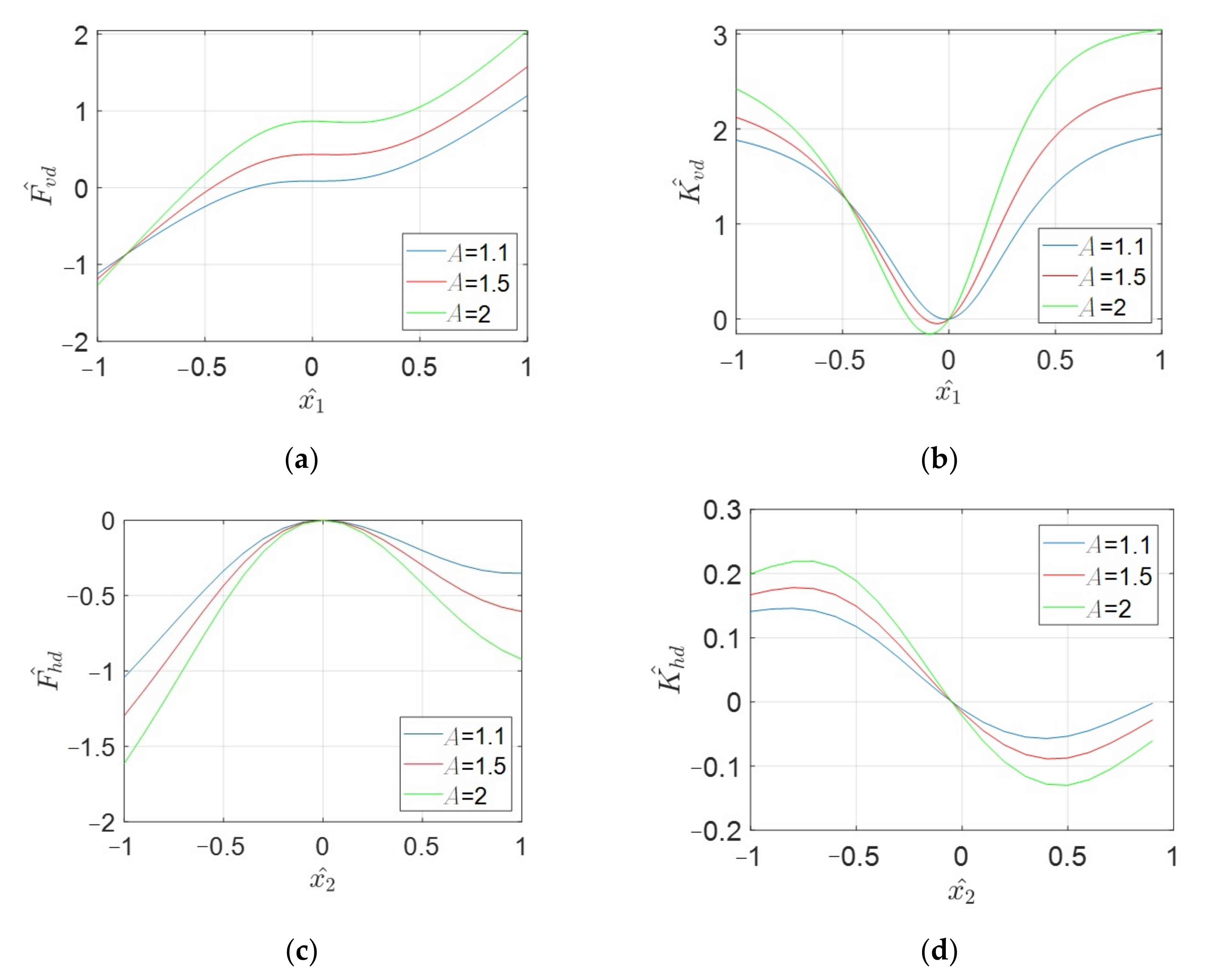
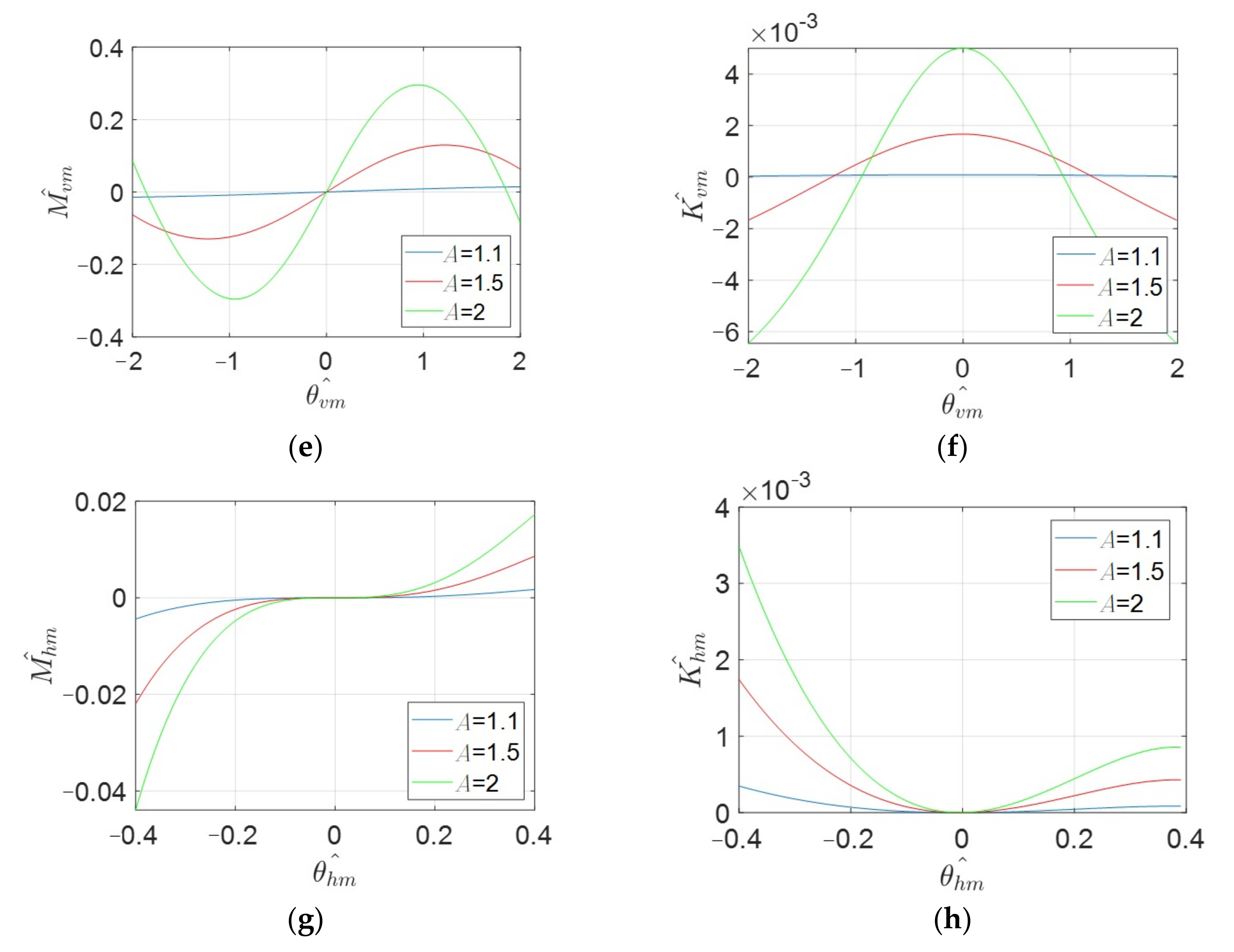
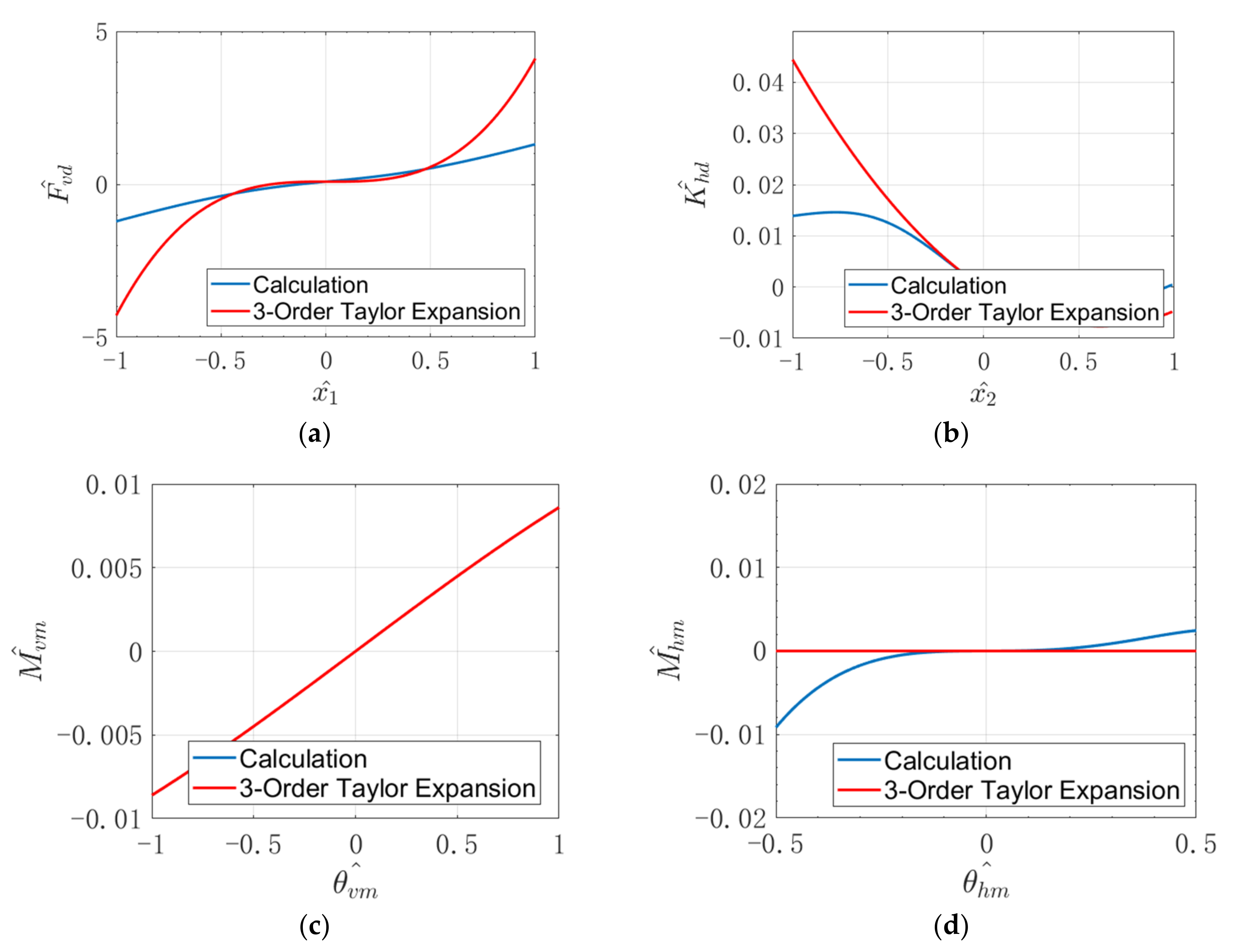
- Through the static analysis in different degrees of freedom, the effects of stiffness and dimension on the stiffness-displacement (rotation angle) relationship of the vibration isolation system are obtained.
- The influences of the damping and dimension parameters on the stability of the system were obtained through dynamic analysis. Moreover, the transmissibility characteristics were analyzed to evaluate the vibration isolation performance of the essential parameters determined in the static analysis and stability analysis. It is indicated that the system will tend to be more stable and there will be a better vibration isolation effect when the damping and length parameters increase. Besides, the bifurcation of the isolation system will be caused as the amplitude of the excitation force increases, so that the vibration isolation effect will also decrease.
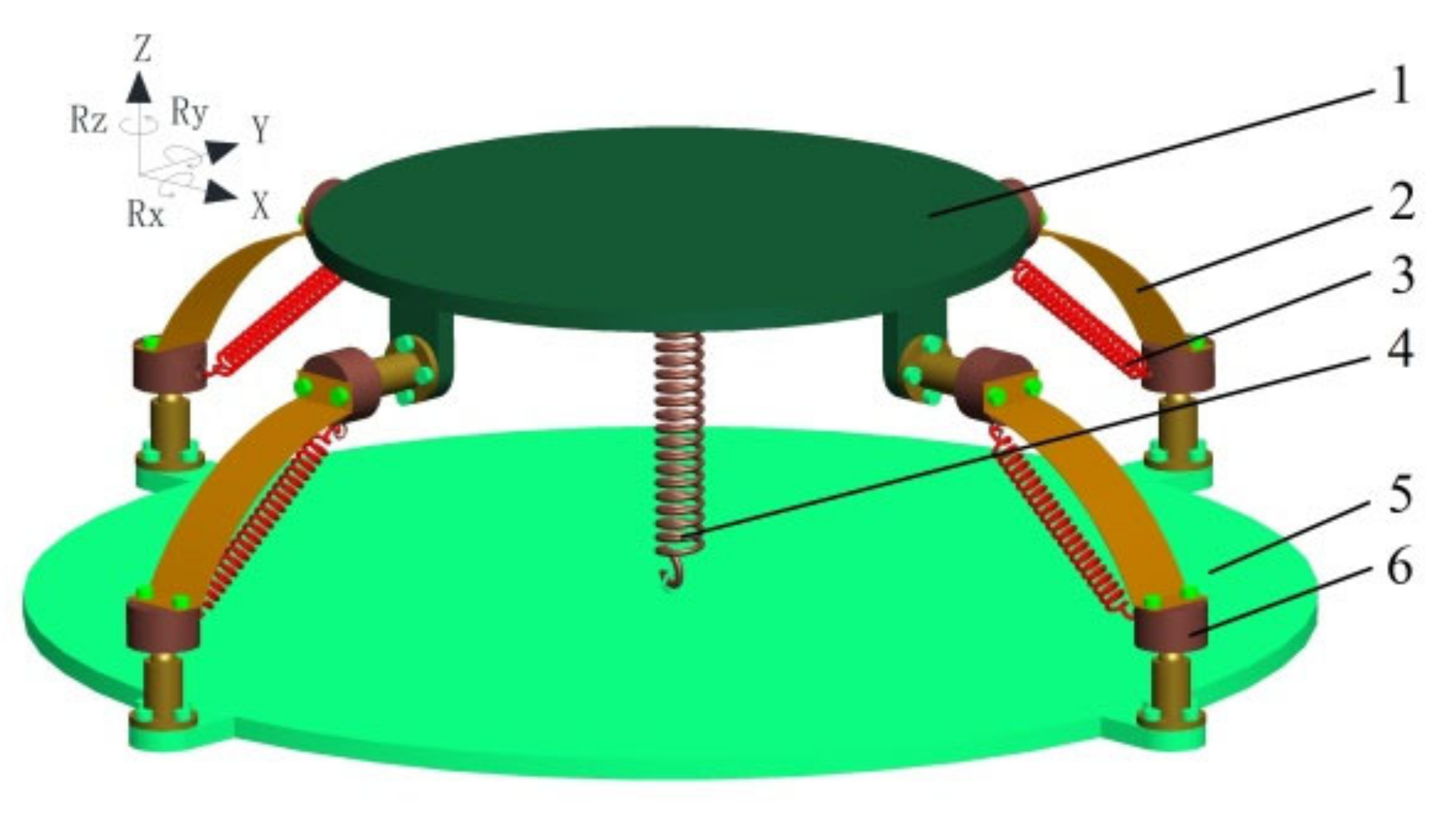
2. Structural Description
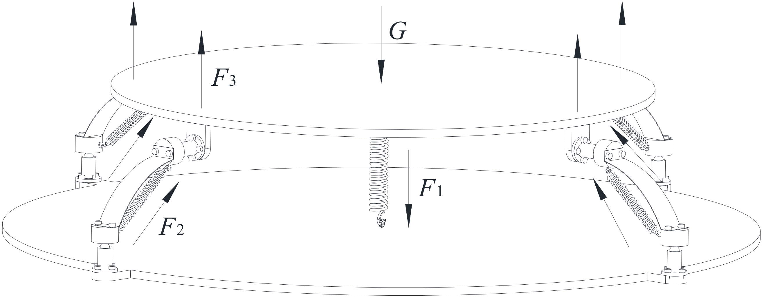
2.1. Structure and Mechanism
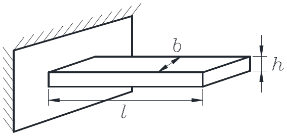
2.2. Stiffness Analysis of Leaf Spring
3. Static Analysis
3.1. Establishment of Statics Model
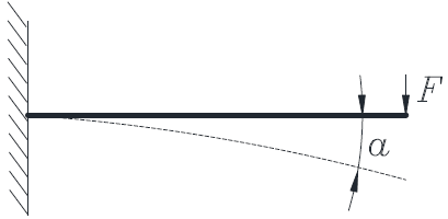
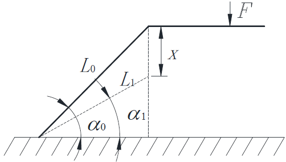
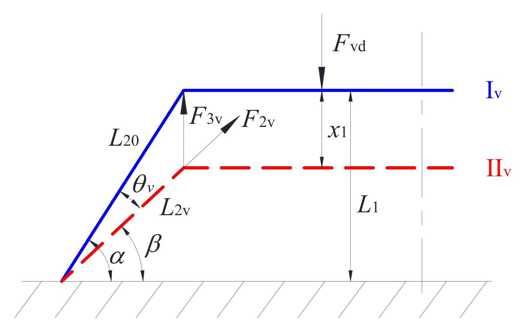
3.1.1. Vertical Displacement
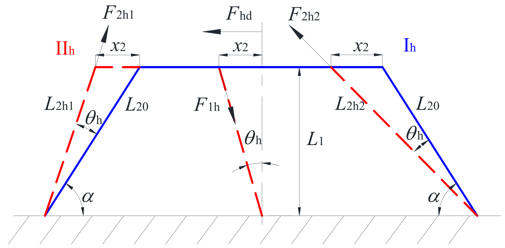
3.1.2. Horizontal Displacement
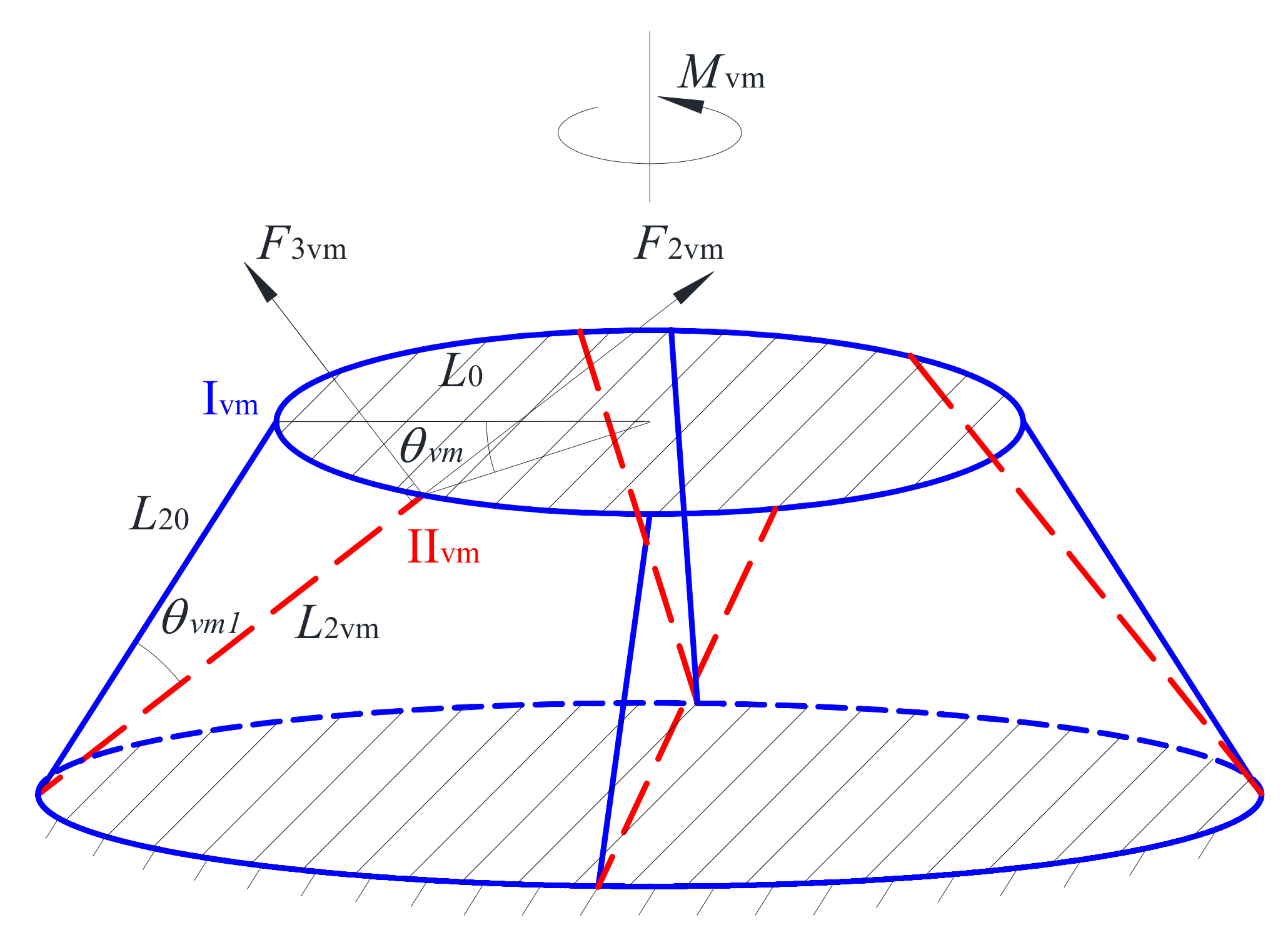
3.1.3. Vertical Rotation
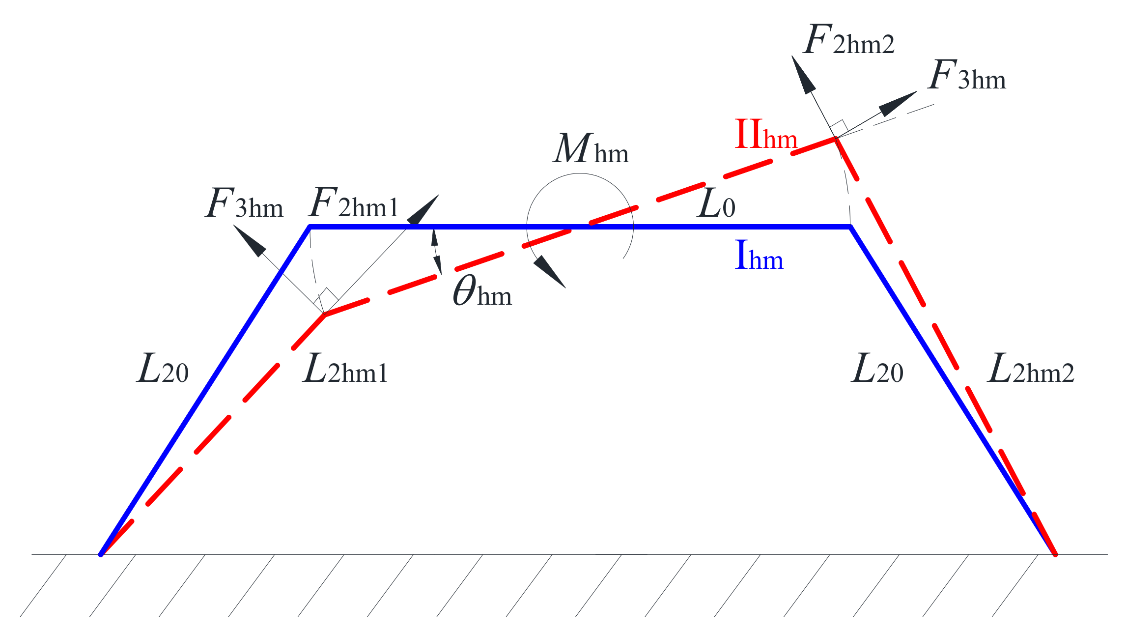
3.1.4. Horizontal Rotation
3.2. Relations of Force (Torque), Stiffness, and Displacement (Rotation Angle)
3.2.1. Vertical Displacement
3.2.2. Horizontal Displacement
3.2.3. Vertical Rotation
3.2.4. Horizontal Rotation
4. Dynamic Analysis
4.1. Establishment of Dynamic Models
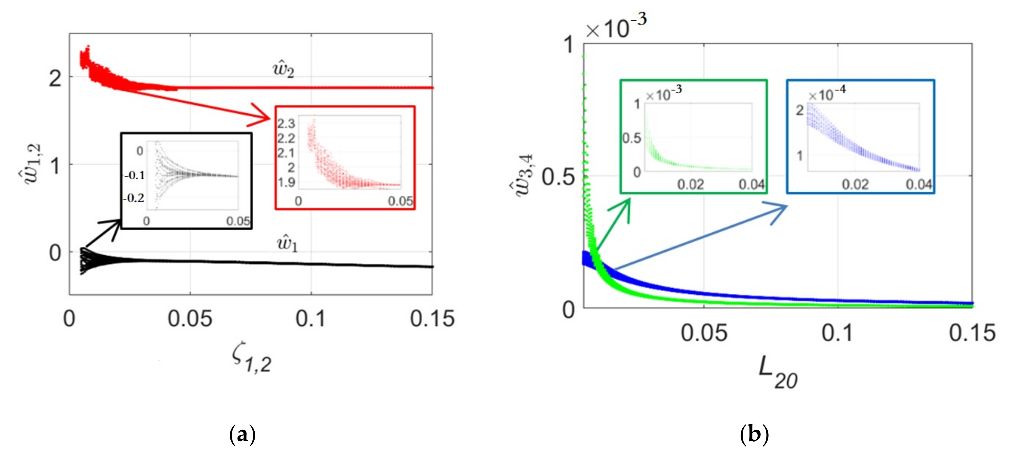
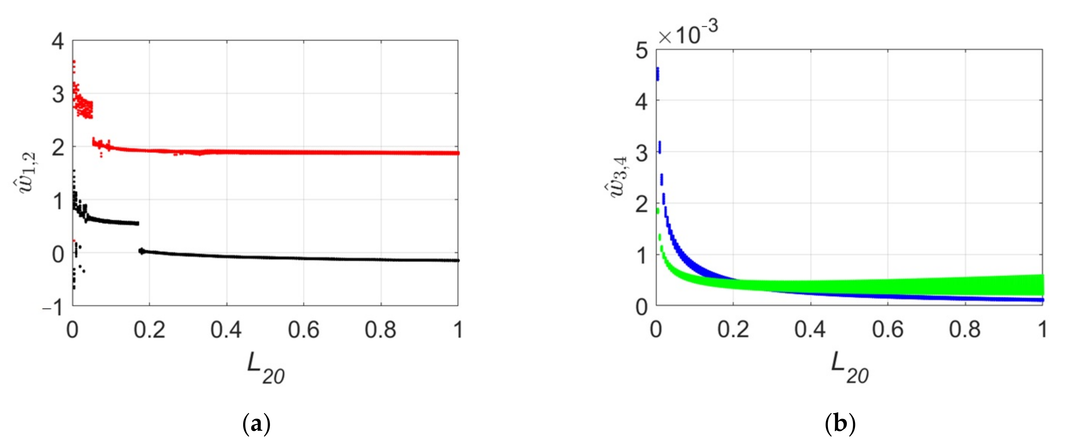
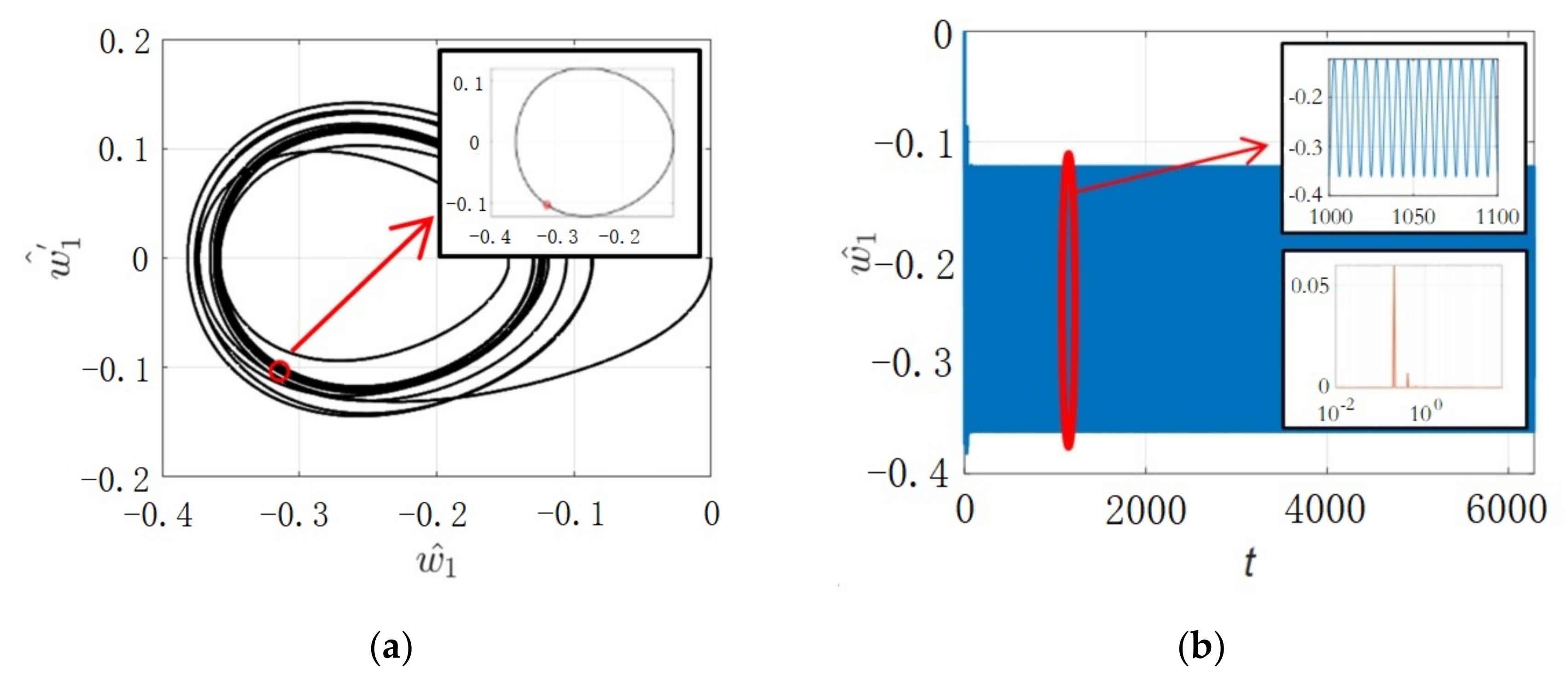
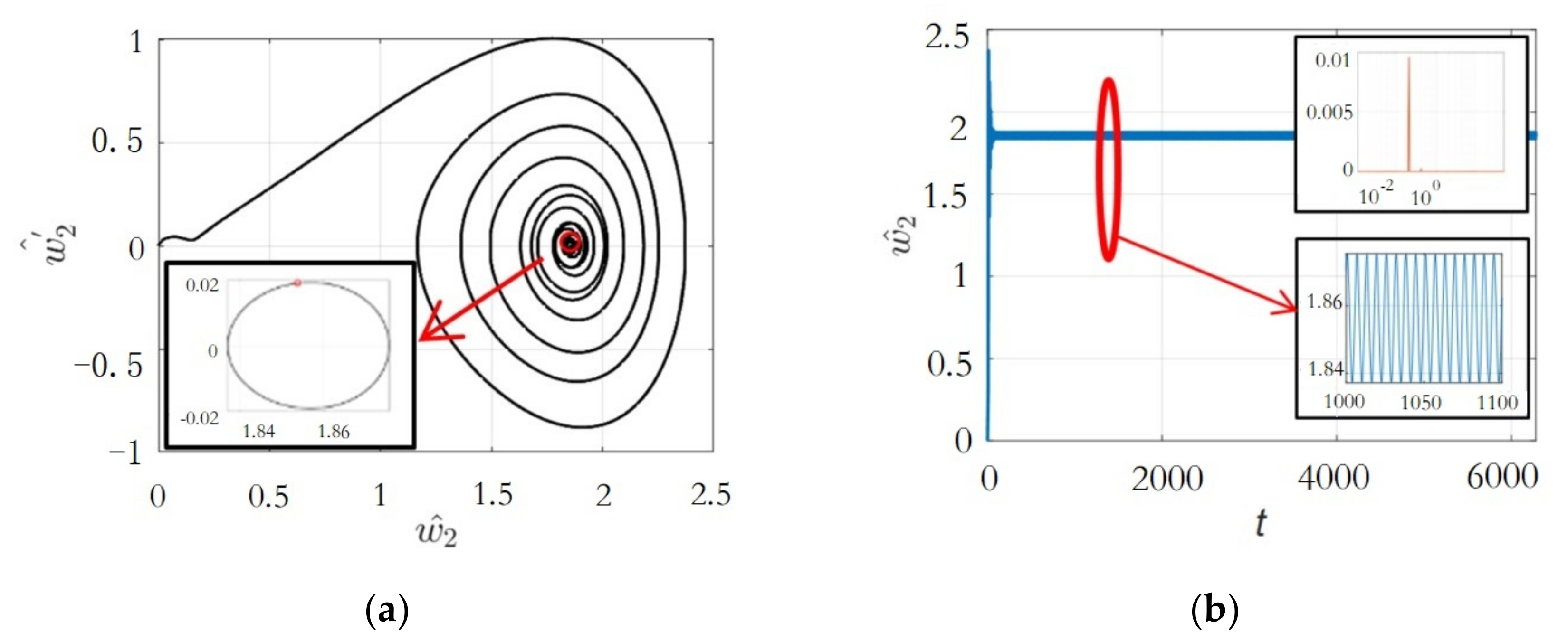
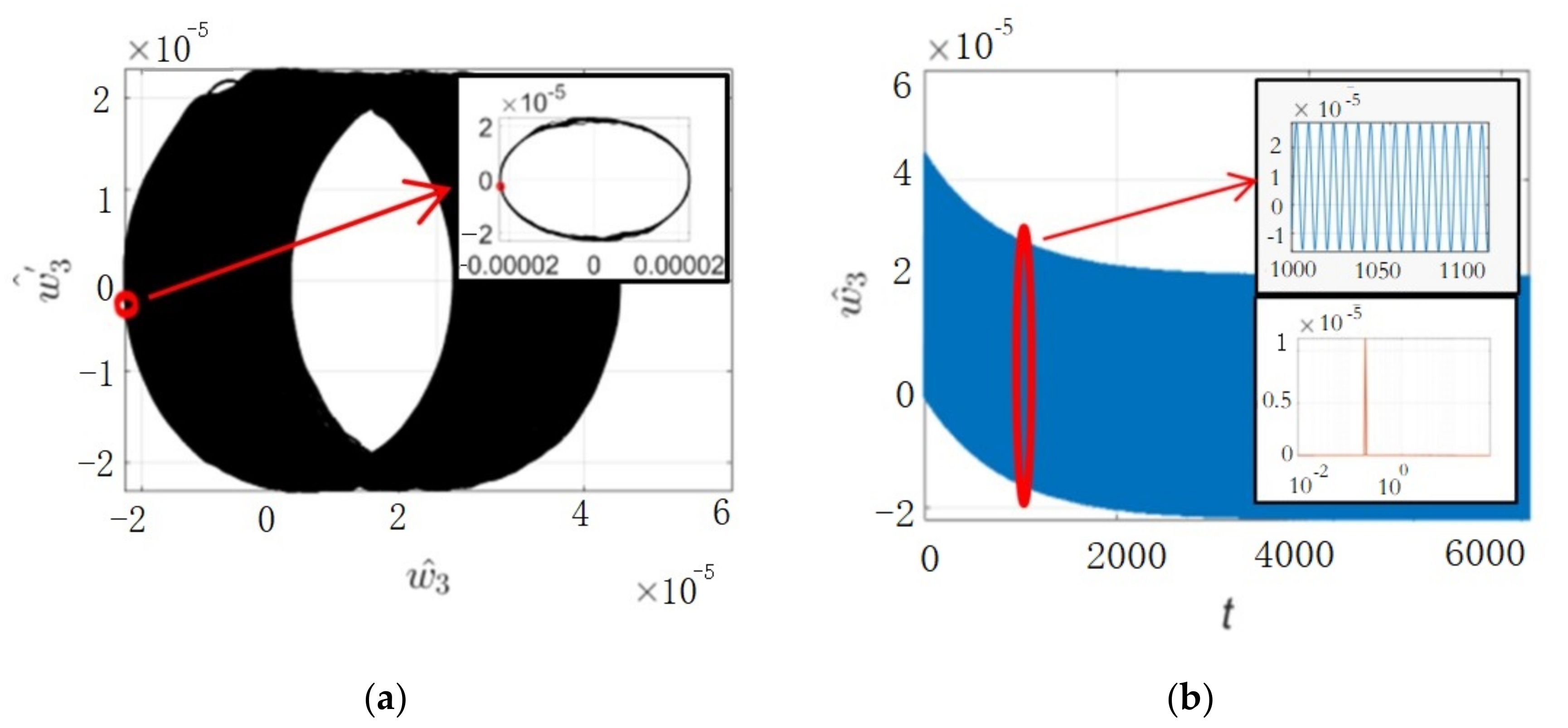
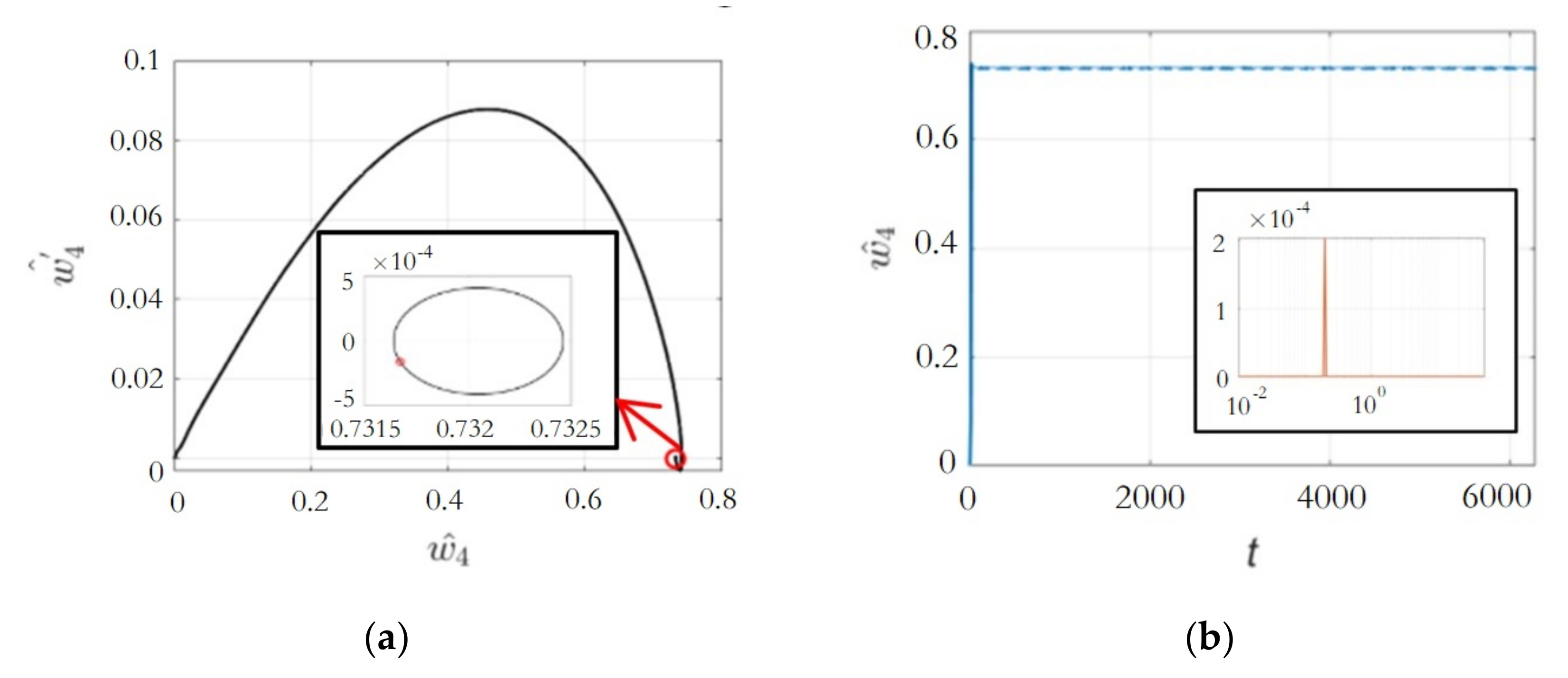
4.2. Stable Analysis
4.2.1. Damping
4.2.2. Slant Length
4.2.3. Periodical Analysis
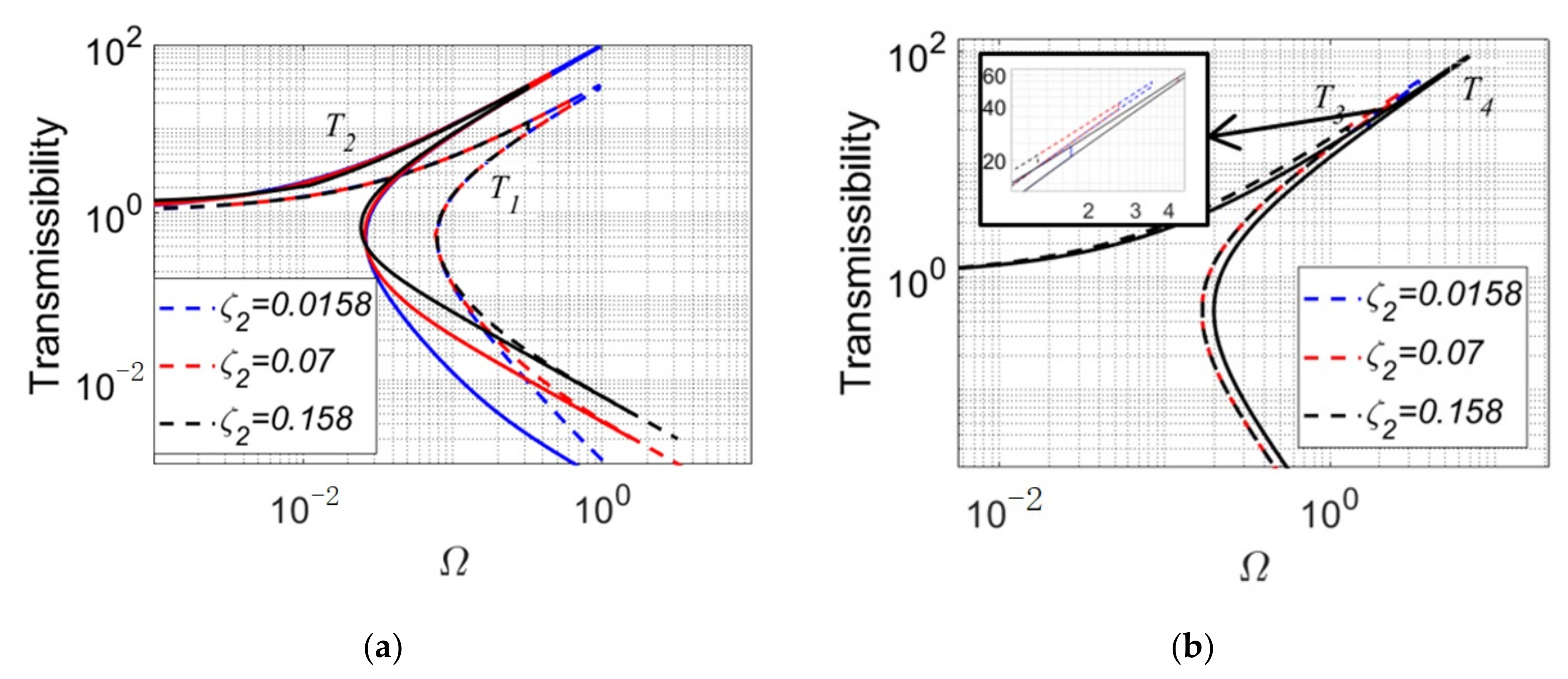
4.3. Characteristics of Transmissibility
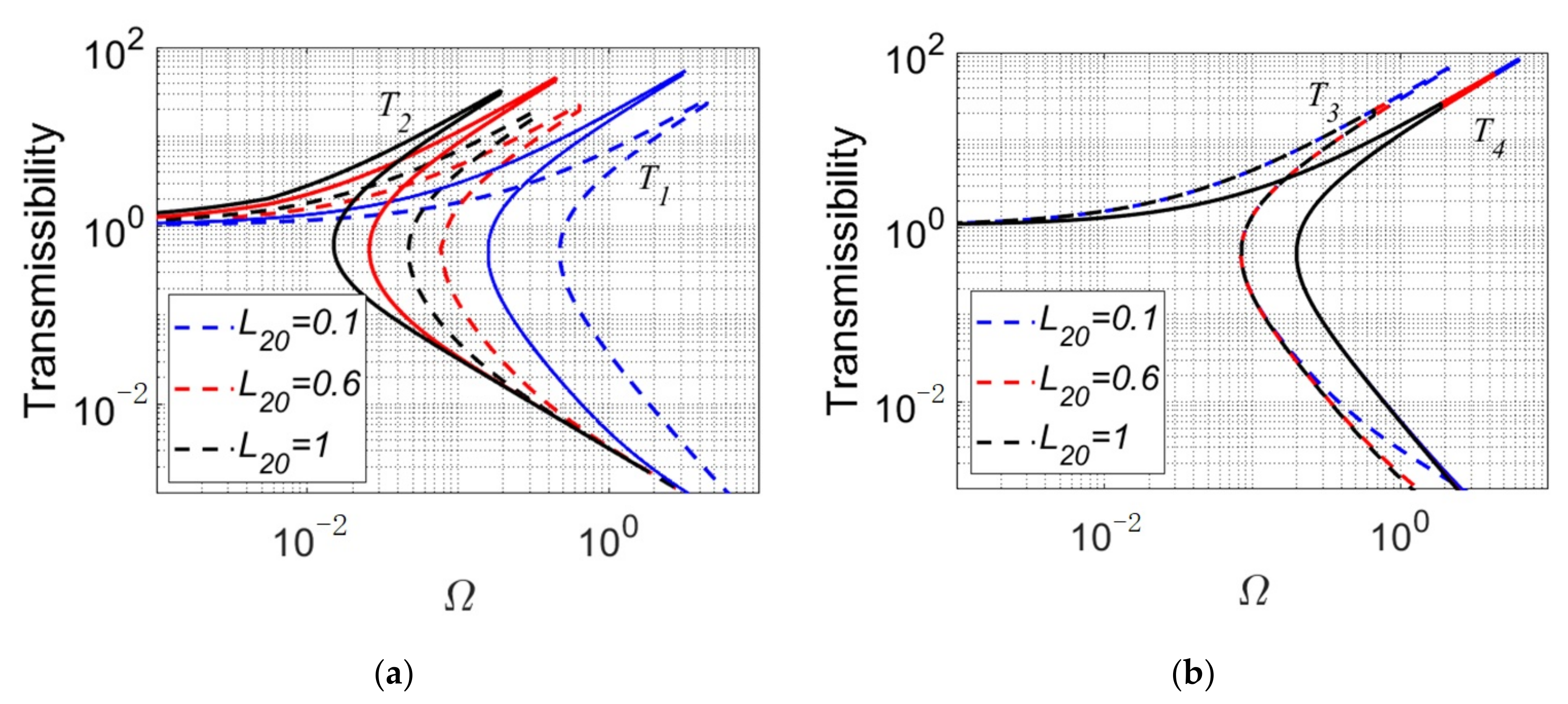
4.3.1. Damping
4.3.2. Slant Length
5. Experimental Investigation
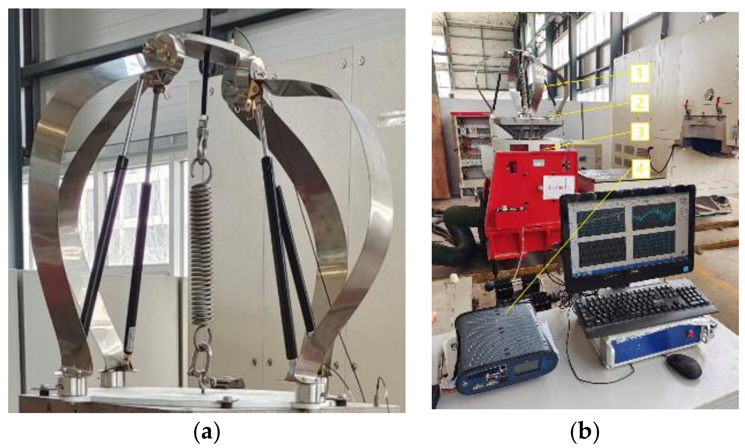
5.1. Experimental Instrument Setup
5.2. Experiment Analysis
6. Conclusions
- (1)
- Three design parameters, including A, , and , have the greatest influence on the vibration isolation performance of the platform, in which, in order to make the stiffness of the isolation system close to zero, the value of A should be near to 1, and the values of and should be minimal under the premise of ensuring the static load capacity of the system;
- (2)
- The load capacity of the isolator is mainly related to the stiffness of the leaf spring and the deformation of the central spring under static load. Besides, in order to ensure that the stiffness of the system is close to zero, the stiffness of the suspension spring and the central spring should be as similar as possible.
- (3)
- The system will tend to be more stable and there will be a better vibration isolation effect when the damping and length parameters increase. Besides, the bifurcation of the isolation system will be caused as the amplitude of the excitation force increases, so that the vibration isolation effect will also decrease. The reason for that is the compressing length of the leaf spring and suspension spring will decrease, and there is not any variant in the central spring. Hence, increasing the slant length will improve the vibration isolation effect, nevertheless the unstable response will also be introduced.
- (4)
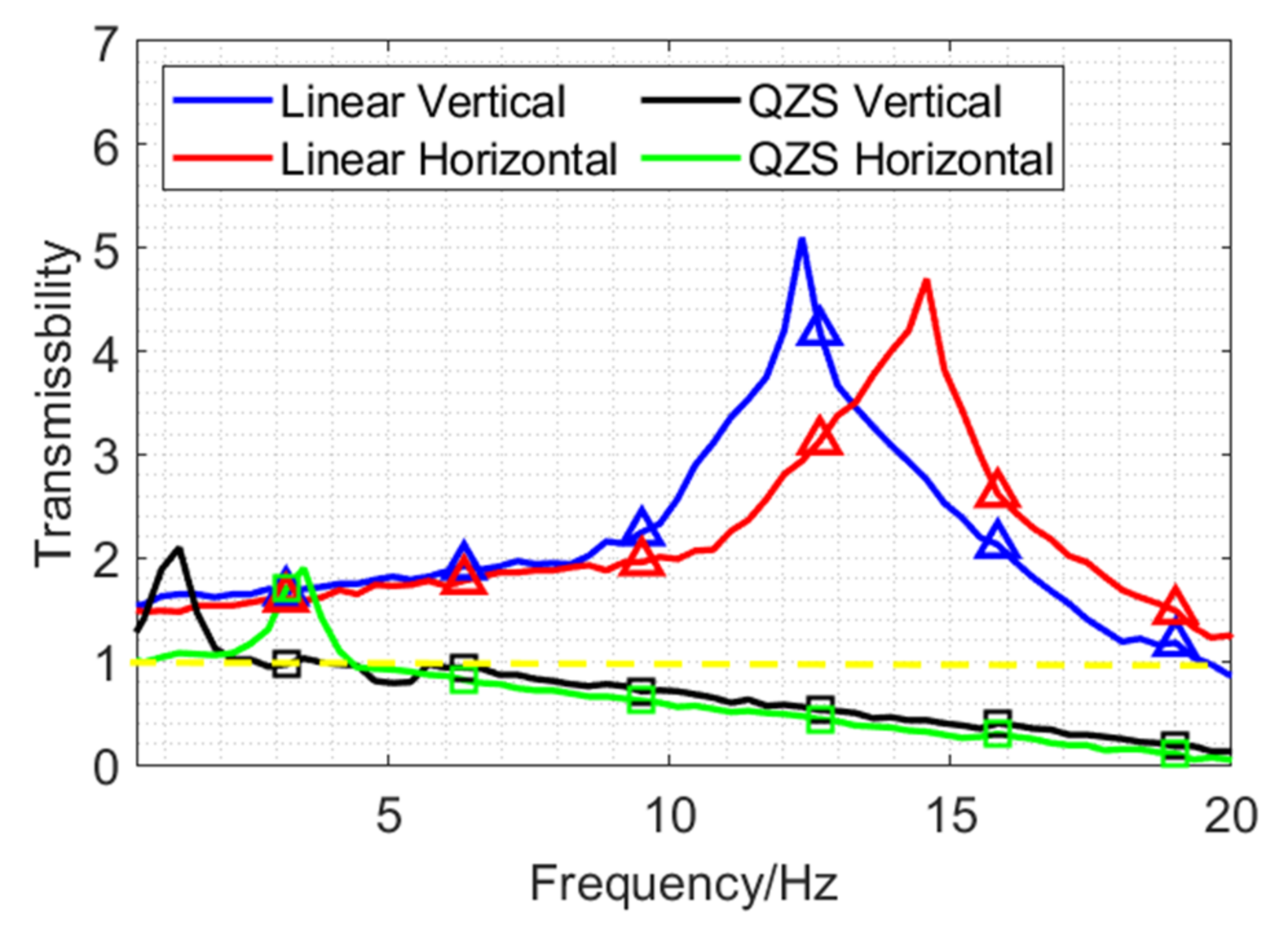
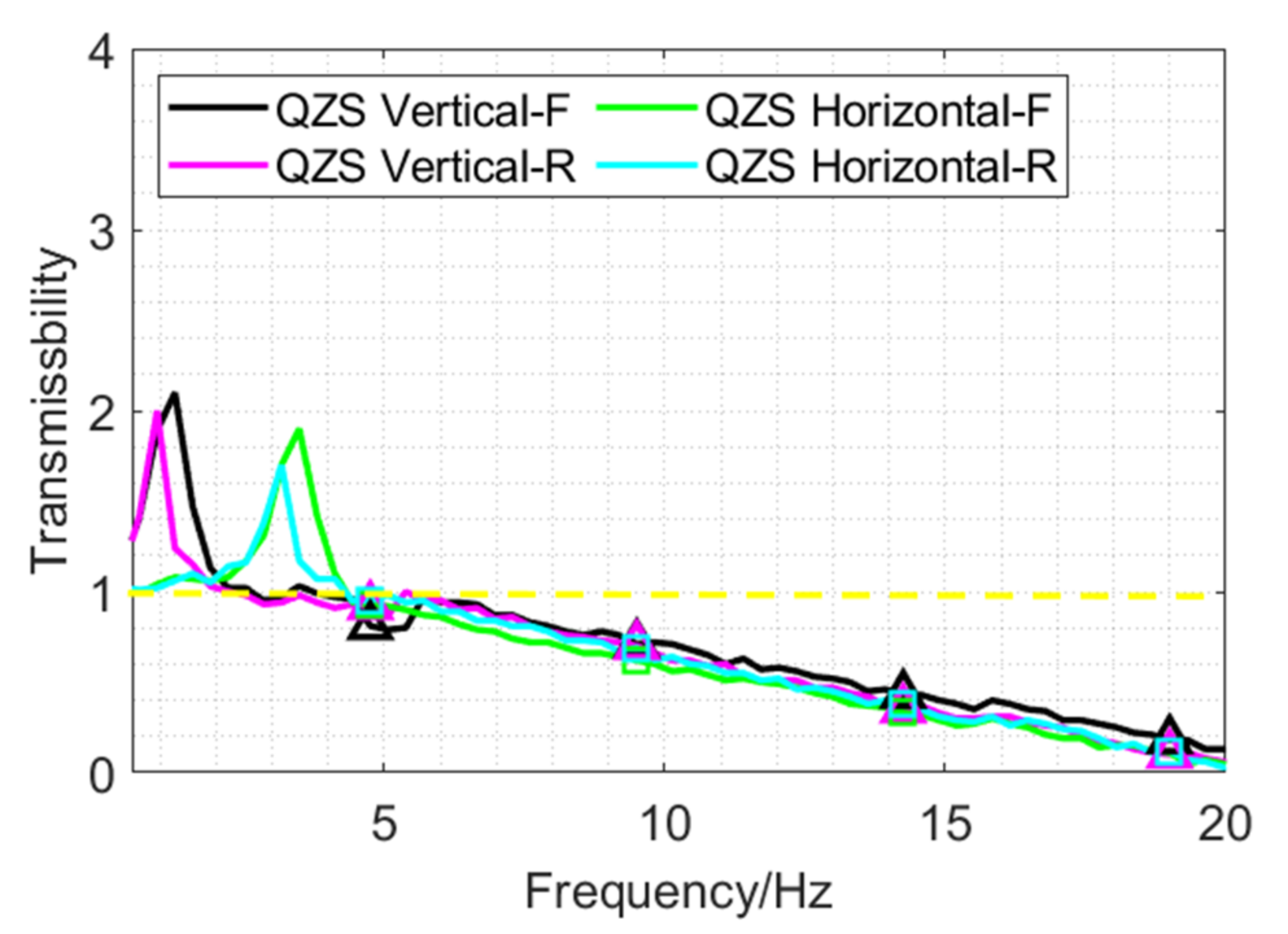
- There is a jumping phenomenon in the QZS vibration isolation platform, and its jumping interval are 0.32 Hz (vertical) and 0.31 Hz (horizontal). Through the experiment, the cause of the jump phenomenon is caused by the inconsistency between the jump frequency and the jump frequency generated in the forward and reverse frequency sweep.
Author Contributions
Funding
Institutional Review Board Statement
Informed Consent Statement
Data Availability Statement
Conflicts of Interest
Nomenclature
| Parameters | Symbol | Parameters | Symbol |
| Ratio of k1 and k2 | A | Length of suspension spring in horizontal displacement | L2h1, L2h2 |
| Width of the leaf spring | b | Length of suspension spring in horizontal rotation | L2hm1, L2hm2 |
| Damping | Ci | Length of suspension spring in vertical displacement | L2v |
| Elasticity modulus | E | Bearing capacity of the platform | m |
| Lord force | F | Torque around the vertical axis | Mvm |
| Tensile force provided by the central spring | F1 | Torque around the horizontal axis | Mhm |
| Tensile force provided by the suspension spring | F2 | Transmissibility | Ti |
| Vertical force | Fvd | Vertical displacement of the isolator bearing the static load force | x0 |
| Horizontal force | Fhd | Downward displacement of the top plate | x1 |
| Elastic force of suspension spring in vertical displacement | F2v | Leftward displacement of the top plate | x2 |
| Elastic force of suspension spring in horizontal displacement | F2h1, F2h2 | ||
| Elastic force of suspension spring in vertical rotation | F2vm | Greek letters | |
| Elastic force of suspension spring in horizontal rotation | F2hm1, F2hm2 | Rotation angle of the leaf spring | α, β |
| Elastic force of leaf spring in vertical displacement | F3v | Product of ω0 and t | τ |
| Elastic force of leaf spring in vertical rotation | F3vm | Damping ratio | ζi |
| Elastic force of leaf spring in horizontal rotation | F3hm | Rotation angle of the leaf spring in vertical displacement | θv |
| Acceleration of gravity | g | Rotation angle of the leaf spring in horizontal displacement | θh |
| Amplitude of excitation force | H1,2,3,4 | Rotation angle of the leaf spring in vertical rotation | θvm |
| Stiffness of central spring | k1 | Rotation angle of the leaf spring in horizontal rotation | θhm |
| Stiffness of suspension spring | k2 | ||
| Stiffness of leaf spring | k3 | Superscripts | |
| Stiffness in vertical displacement | kvd | Denotes dimensionless quantity | ^ |
| Initial stretch length of the central spring | L1 | ||
| Radius of top plate | L0 | ||
| Unstretched length of the suspension spring | L20 |
References
- Rivin, E. Passive vibration isolation. Appl. Mech. Rev. 2003, 57, 31–32. [Google Scholar] [CrossRef]
- Ibrahim, R.A. Recent advances in nonlinear passive vibration isolators. J. Sound Vib. 2008, 314, 371–452. [Google Scholar] [CrossRef]
- Alabuzhev, P.M.; Rivin, E.I. Vibration Protecting and Measuring Systems with Quasi-Zero Stiffness; Hemisphere Publishing Corporation: New York, NY, USA, 1989; pp. 55–78. [Google Scholar]
- Platus, D.L. Negative-stiffness-mechanism vibration isolation systems. Proc. SPIE Int. Soc. Opt. Eng. 1999, 3786, 44–54. [Google Scholar]
- Liu, X.; Huang, X.; Hua, H. On the characteristics of a quasi-zero stiffness isolator using Euler buckled beam as negative stiffness corrector. J. Sound Vib. 2013, 332, 3359–3376. [Google Scholar] [CrossRef]
- Kovacic, I.; Brennan, M.J.; Waters, T.P. A study of a nonlinear vibration isolator with a quasi-zero stiffness characteristic. J. Sound Vib. 2008, 315, 700–711. [Google Scholar] [CrossRef]
- Meng, Q.; Yang, X.; Li, W.; Lu, E.; Sheng, L. Research and analysis of quasi-zero-stiffness isolator with geometric nonlinear damping. Shock Vib. 2017, 2017, 6719054. [Google Scholar] [CrossRef] [Green Version]
- Carrella, A.; Brennan, M.J.; Waters, T.P.; Shin, K. On the design of a high-static-low-dynamic stiffness isolator using linear mechanical springs and magnets. J. Sound Vib. 2008, 315, 712–720. [Google Scholar] [CrossRef]
- Shin, K. On the performance of a single degree-of-freedom high-static-low-dynamic stiffness magnetic vibration isolator. Int. J. Precis. Eng. Manuf. 2014, 15, 439–445. [Google Scholar] [CrossRef]
- Shan, Y.; Wu, W.; Chen, X. Design of a miniaturized pneumatic vibration isolator with high-static-low-dynamic stiffness. J. Vib. Acoust. 2015, 137, 045001. [Google Scholar] [CrossRef]
- Robertson, W.S.; Kidner, M.R.F.; Cazzolato, B.S.; Zander, A.C. Theoretical design parameters for a quasi-zero stiffness magnetic spring for vibration isolation. J. Sound Vib. 2009, 326, 88–103. [Google Scholar] [CrossRef]
- Yoshikazu, A.; Kosuke, K.; Takehiko, A.; Takeshi, M.; Toshihiro, O.; Ryosuke, K. Integrated mechanical and material design of quasi-zero-stiffness vibration isolator with superelastic Cu-Al-Mn shape memory alloy bars. J. Sound Vib. 2015, 358, 74–83. [Google Scholar]
- Dai, H.; Jing, X.; Wang, Y.; Yue, X.; Yuan, J. Post-capture vibration suppression of spacecraft via a bio-inspired isolation system. Mech. Syst. Signal Process. 2018, 105, 214–240. [Google Scholar] [CrossRef]
- Wu, Z.; Jing, X.; Bian, J.; Li, F.; Allen, R. Vibration isolation by exploring bio-inspired structural nonlinearity. Bioinspir. Biomim. 2015, 10, 056015. [Google Scholar] [CrossRef]
- Gatti, G. A k-shaped spring configuration to boost elastic potential energy. Smart Mater. Struct. 2019, 28, 077002. [Google Scholar] [CrossRef]
- Gatti, G. Statics and dynamics of a nonlinear oscillator with quasi-zero stiffness behaviour for large deflections. Commun. Nonlinear Sci. 2020, 83, 105143. [Google Scholar] [CrossRef]
- Kim, G.W.; Kang, J. The V-shaped band-stop vibration isolator inspired by middle ear. Appl. Acoust. 2019, 150, 162–168. [Google Scholar] [CrossRef]
- Wu, Z.; Jing, X.; Sun, B.; Li, F. A 6DOF passive vibration isolator using x-shape supporting structures. J. Sound Vib. 2016, 380, 90–111. [Google Scholar] [CrossRef]
- Zhou, J.; Xiao, Q.; Xu, D.; Ouyang, H.; Li, Y. A novel quasi-zero-stiffness strut and its applications in six-degree-of-freedom vibration isolation platform. J. Sound Vib. 2017, 394, 59–74. [Google Scholar] [CrossRef]
- Wang, Y.; Liu, H. Six degree-of-freedom microvibration hybrid control system for high technology facilities. J. Struct. Stab. Dyn. 2009, 9, 437–460. [Google Scholar] [CrossRef]
- Zhang, Y.; Chen, Z.; Jiao, Y. A hybrid vibration isolator: Design, control, and experiments. Proc. Inst. Mech. Eng. Part C J. Mech. Eng. Sci. 2016, 230, 2982–2995. [Google Scholar] [CrossRef]
- Touze, C.; Vizzaccaro, A.; Thomas, O. Model order reduction methods for geometrically nonlinear structures: A review of nonlinear techniques. Nonlinear Dyn. 2021, 105, 1141–1190. [Google Scholar] [CrossRef]


| Parameters | Symbol | Value |
|---|---|---|
| Stiffness of central spring | k1 | 20,000 N/m |
| Stiffness of suspension spring | k2 | 22,000 N/m |
| Stiffness of leaf spring | k3 | 2000 N/m |
| Initial length of central spring | L1 | 0.52 m |
| Initial length of suspension spring | L20 | 0.6 m |
| Radius of top plate | L0 | 0.06 m |
| Damping | Ci | 44.3 N·m |
| Excitation amplitude | Hi | 0.1 m |
| Static load | m | 50 kg |
| Components | Material |
|---|---|
| Central spring | Stainless steel |
| Suspension spring | Stainless steel |
| Leaf spring | Mn-steel |
| Top and base plates | Stainless steel |
| Spherical hinge | Stainless steel |
| Screws and fastenings | Stainless steel |
| Type | d-mm | D-mm | n | L-mm | k-N/m |
|---|---|---|---|---|---|
| Central spring | 10 | 60 | 23 | 465 | 19,973 |
| Suspension spring | 8 | 35 | 42 | 607 | 22,570 |
| Instruments | Models | Parameters |
|---|---|---|
| Vibration table | ACT2000-R0225S, CMI | Max. Force: 22 kN, Max. Acceleration: 1000 m/s2, Frequency Range: 1~3000 Hz. |
| Accelerometer | 4529-B, B&K | Sensitivity: 10 mV/ms−2, Frequency range: 0.3~6.0 kHz, Weight: 14.5 g. |
| Data Acquisition System | CRONOS-PL-3, imc | 16 channels, Max. sampling rate: 400 kS/s |
Publisher’s Note: MDPI stays neutral with regard to jurisdictional claims in published maps and institutional affiliations. |
© 2022 by the authors. Licensee MDPI, Basel, Switzerland. This article is an open access article distributed under the terms and conditions of the Creative Commons Attribution (CC BY) license (https://creativecommons.org/licenses/by/4.0/).
Share and Cite
Wang, Z.; He, C.; Xu, Y.; Li, D.; Liang, Z.; Ding, W.; Kou, L. Static and Dynamic Analysis of 6-DOF Quasi-Zero-Stiffness Vibration Isolation Platform Based on Leaf Spring Structure. Mathematics 2022, 10, 1342. https://doi.org/10.3390/math10081342
Wang Z, He C, Xu Y, Li D, Liang Z, Ding W, Kou L. Static and Dynamic Analysis of 6-DOF Quasi-Zero-Stiffness Vibration Isolation Platform Based on Leaf Spring Structure. Mathematics. 2022; 10(8):1342. https://doi.org/10.3390/math10081342
Chicago/Turabian StyleWang, Zhen, Chuanlin He, Yan Xu, Dong Li, Zhanyuan Liang, Wei Ding, and Lei Kou. 2022. "Static and Dynamic Analysis of 6-DOF Quasi-Zero-Stiffness Vibration Isolation Platform Based on Leaf Spring Structure" Mathematics 10, no. 8: 1342. https://doi.org/10.3390/math10081342