Article

Fracture Process and Failure Mode of Brazilian Discs with Cracks of Different Angles: A Numerical Study

1
School of Resources and Safety Engineering, Central South University, Changsha 410083, China
2
College of Urban and Rural Construction, Shaoyang University, Shaoyang 422099, China
3
Yunnan Energy Investment New Energy Industrial Park Investment Development Co., Ltd., Kunming 650501, China
*
Author to whom correspondence should be addressed.
Mathematics 2022, 10(24), 4808; https://doi.org/10.3390/math10244808
Submission received: 21 October 2022 / Revised: 13 December 2022 / Accepted: 15 December 2022 / Published: 17 December 2022
(This article belongs to the Special Issue Advanced Numerical Analysis and Scientific Computing)

Abstract

:
In order to determine the effect of internal cracks on the tensile failure of materials, a hybrid finite–discrete element method was used to analyze the Brazilian disc test with cracks of different angles. When the pre-crack angle is between 0° and 60°, the wing crack is initiated from the pre-crack end. When the pre-crack is 90°, the crack initiated from the pre-crack center. When the pre-crack angle is between 0° and 60°, the maximum principal stress and plastic strain are concentrated at the pre-crack end. When the pre-crack angle is 90°, the maximum principal stress and plastic strain are concentrated in the pre-crack center. As the crack angle increased from 0° to 90°, the failure mode of Brazilian discs with cracks transits from splitting into two parts to splitting into four parts. The influence of crack length is further studied. When the crack length is less than 5 mm, the crack angle has little influence on the disc failure mode; Brazilian discs with cracks of different angles undergoes splitting failure along the loading axis. When the crack length is larger than 5 mm, the crack angle has a great effect on the disc failure mode.

1. Introduction

Brittle materials such as concrete and rock are the main components in mining engineering and civil engineering, and the failure of brittle materials is a complex evolution process [1,2,3,4]. Because the tensile strength of brittle materials is much smaller than their compressive strength, the failure of brittle materials is mainly caused by tensile fracture propagation in most cases [5,6,7]. In order to obtain the tensile strength of brittle materials, ISRM recommends the Brazilian disc test as an indirect method for tensile testing [8], which has the advantages of simple sample preparation and testing procedures. According to Hondor’s analytical solution [9], a large portion of a Brazilian disc is in a tensile stress state in the horizontal direction.
Since the Brazilian disc test was proposed by Carneiro and Akazawa [10,11], many scholars have carried out various studies on the Brazilian disc test [12,13,14,15,16,17,18,19]. Hudson and Swab et al. [20,21] found that the crack initiation point and maximum tensile strain of Brazilian discs tended to be far away from the center of the disc in a plate-loaded Brazilian disc tensile test. Li et al. [22] proposed a theory of maximum tensile strain for judging the initiation point of the Brazilian disc. This could explain the phenomenon wherein the cracking point deviates from the center in some Brazilian disc tests. In addition, Li et al. [23] observed the tensile strain of Brazilian discs under different loading configurations through digital image correlation techniques, and discussed the effectiveness of loading configurations. It was found that curved jaw loading was best for the Brazilian disc test, and that small-diameter rod loading was not suitable for the Brazilian disc test.
Brittle materials such as rock mass and concrete usually contain joints and fissures, which often dominate the failure process of brittle materials [24,25,26,27,28,29]. Therefore, many scholars have studied the effect of cracks on rock failure under various conditions [30,31,32,33,34]. In order to study the effect of cracks on the tensile failure of brittle materials, some scholars have carried out the Brazilian disc test with cracks [35,36,37]. Luo et al. [38] studied the Brazilian disc test with different angles of cracks and found that with an increase in the crack angle, the peak load of the disc first decreased and then increased. Xiao et al. [31] studied cuboid granite with cracks of different angles under coupled static and dynamic loads, and found that with a decrease in crack angle, the dynamic strength and combined static and dynamic strength of granite decreased. In physical testing, it is difficult to obtain some important information such as stress field, strain field and damage evolution of discs with cracks. The numerical methods can make up for these deficiencies. For example, Haeri et al. [39] simulated the failure process of prefabricated holes and cracks in Brazilian discs by PFC3D and found that the main failure mode remained unchanged in tensile failure with an increase in ball diameter. Chang et al. [40] carried out numerical calculations on Brazilian discs with cracks with different angles using the embedded viscous CZM method, and obtained the effect of crack angles on the crack propagation of discs.
Among the existing studies on Brazilian discs with cracks, some studies focused on the analysis of mode I fracture and mode II fracture toughness, and some studies focused on the effects of crack angle on the failure process, failure mode and peak load of the disc [41,42,43,44]. The evolution of the stress field and strain field in the fracture process of Brazilian discs with cracks of different angles is important for analyzing the effect of cracks on the tensile failure and fracture behavior of brittle materials. In this study, the stress field, damage strain field and fracture process of Brazilian discs with cracks are analyzed. The influence of crack angle and length on the Brazilian disc is further discussed, and can explain some phenomena regarding indirect tensile strength differences in materials caused by internal defects.

2. Numerical Methods and Models

2.1. Numerical Methods

Among the commonly used numerical calculation methods, the finite element method is difficult to simulate the fracture process of materials with, and the discrete element method has some defects in simulating the continuum. In recent years, a hybrid finite element and discrete element method (FDEM) has been developed and applied. The method divides the numerical model into finite element domains and inserts new cracks into the finite elements by introducing fracture mechanics criteria to realize the fracture process of continuum [45,46,47,48]. A hybrid program called ELFEN simulates the fracture process of materials by increasing the strain of materials during loading [49,50,51,52]. The method determines the internal element and inter-element fractures according to the failure plane, which makes the fracture process more realistic.
The crack initiation, propagation and coalescence of the model in the hybrid program are the result of the increase in tensile strain. In addition to the tensile stress field, the model also expands in the orthogonal direction due to the Poisson effect under the compressive stress field. The CAI’s research shows that the shear failure of brittle materials under uniaxial compression is caused by the propagation and coalescence of tensile micro-cracks in materials [53]. The traditional Mohr–Coulomb failure criterion exaggerates the tensile strength of materials. The Rankine failure criterion is suitable to judge tensile failure. The Mohr–Coulomb with Rankine failure criterion is used to better judge the tensile and shear fracture behavior of brittle materials in this study. A detailed introduction to this numerical method can be seen in earlier studies [52,54].

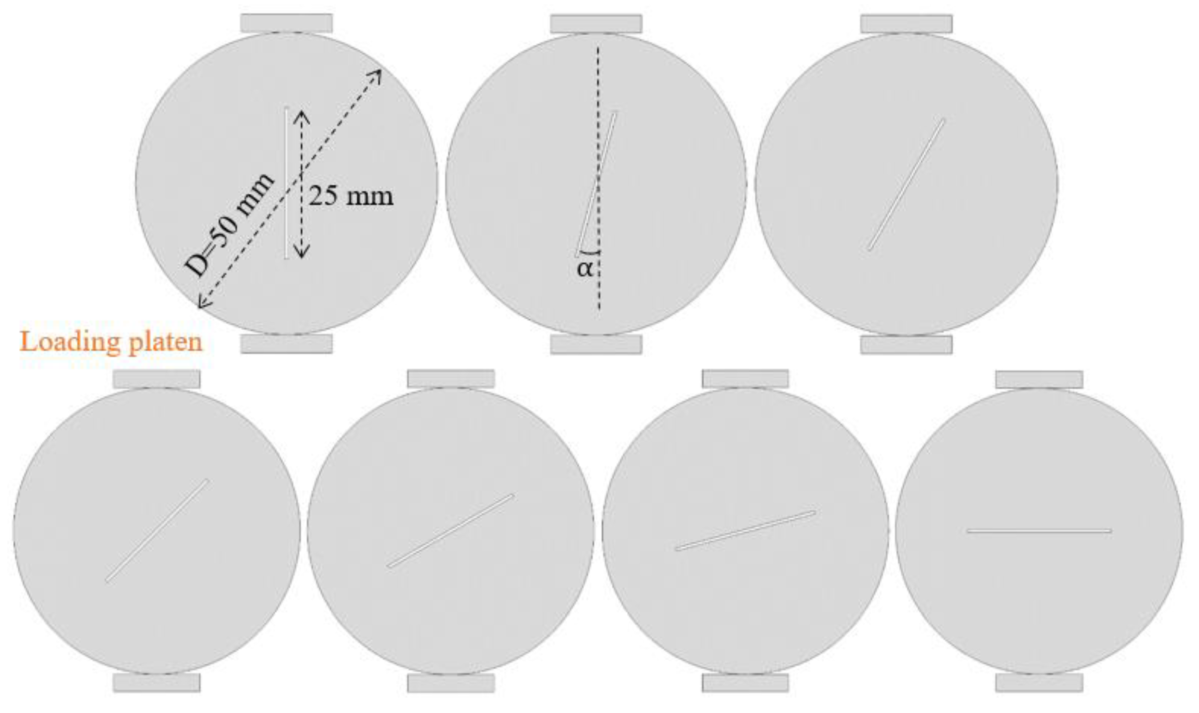
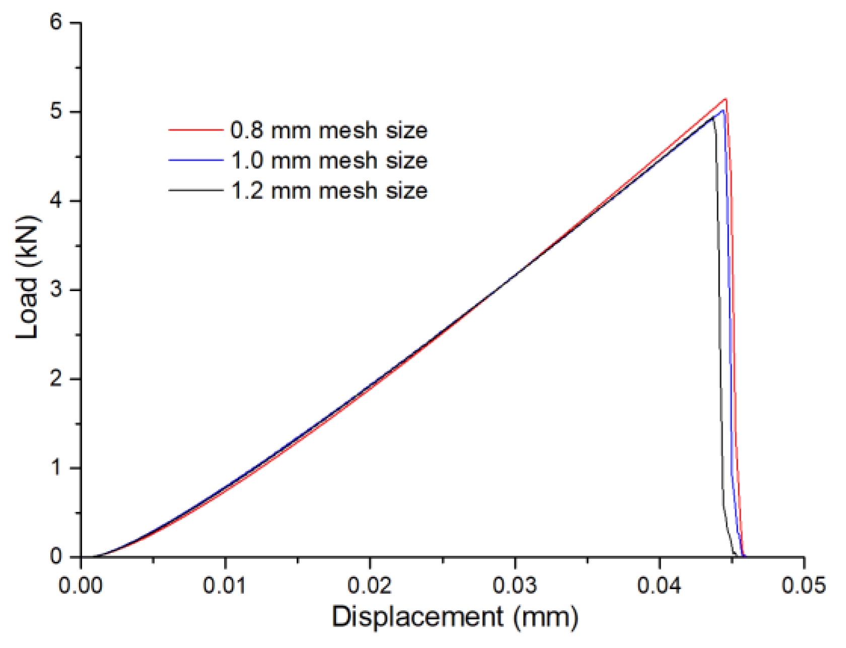
2.2. Brazilian Disc with Crack Models

Seven Brazilian disc models with cracks of different angles were built, as shown in Figure 1. The disc diameter (D) is 50 mm, the disc thickness (T) is 25 mm, the crack length (L) is 25 mm, the crack width is 0.5 mm and the crack is located in the disc’s center. The crack angle α   is defined as the angle between the crack’s direction and the loading direction; α ranges from 0° and 90°. Velocity loading was selected as the loading type. The loading velocity was 1 mm/s, and the strain rate was 0.02 s−1, which constituted quasi-static loading.
The granite material in Li’s research [23] was chosen as the disc material in the model. The uniaxial compression strength was 171.7 MPa and the indirect tensile strength was 12.8 MPa. In this study, the friction angle for the material was set to 28° and the cohesion was set to 51 MPa. The material properties for the model are shown in Table 1. The normal penalty is generally 1.0 times the elastic modulus, and the tangential penalty is generally 0.1 times the normal penalty. The mesh element size was 0.8mm, and the diameter of discs was 62 times the mesh size. The influence of mesh size on Brazilian discs with cracks is shown in in Appendix A.

3. Results

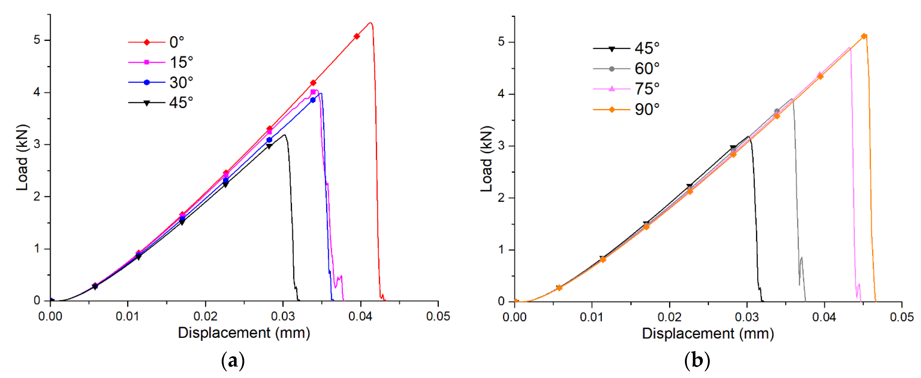
3.1. Load–Displacement Curve

Figure 2 shows the load–displacement curves for the Brazilian discs with cracks of different angles. The seven curves include the initial compaction stage, elastic stage and post-peak stage. The initial compaction stage is shorter and the elastic stage is longer. When the crack angle is between 0° and 45°, as can be seen from Figure 2a, the peak load and curve slope of the disc decrease gradually as the crack angle increases. When the crack angle is between 45° and 90°, as can be seen from Figure 2b, the angle increases, both the peak load and peak displacement of disc gradually decrease and the slope of the curve increases slightly.
The peak load and peak displacement of the Brazilian disc with the 0° crack are 5.34 kN and 0.041 mm, respectively. The peak load and peak displacement of the Brazilian disc with the 45° crack are 3.19 kN and 0.030 mm, respectively. The peak load and peak displacement of the Brazilian disc with the 90° crack are 5.15 kN and 0.045 mm, respectively. The Brazilian disc with the 0° crack has the largest peak load, the Brazilian disc with the 90° crack has the largest peak displacement, and the Brazilian disc with the 45° crack has the smallest peak load and peak displacement.

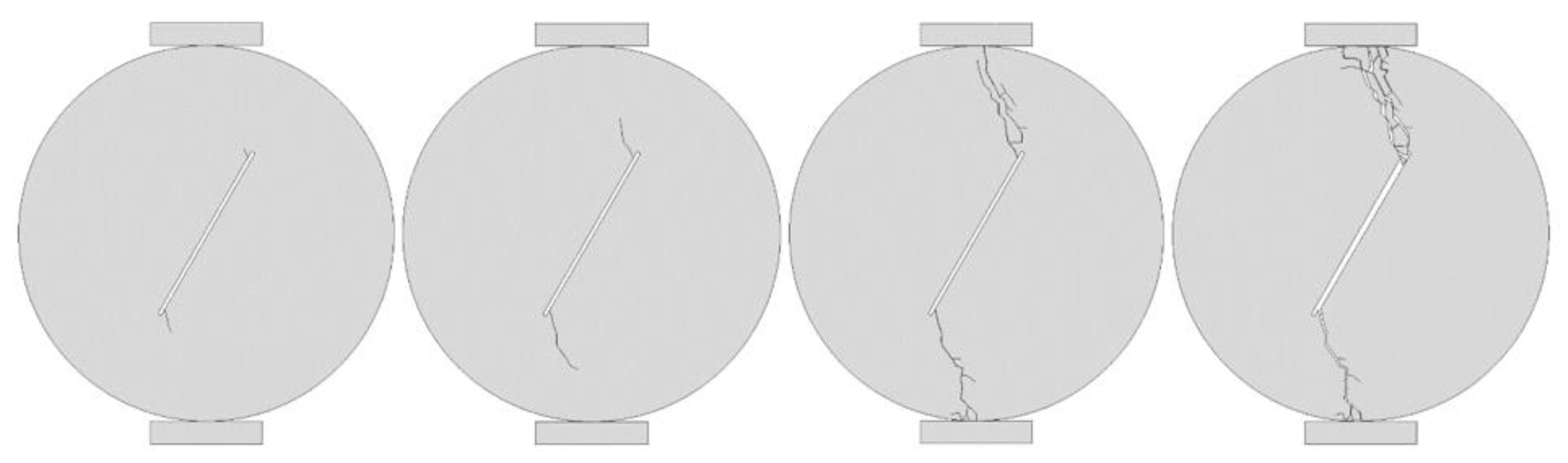
3.2. Fracture Process

Figure 3, Figure 4, Figure 5, Figure 6, Figure 7, Figure 8 and Figure 9 show the crack propagations for the Brazilian discs with cracks of different angles. The failure process includes crack initiation, crack propagation, crack penetration, and failure. Figure 3 shows the fracture process of the Brazilian disc with the 0° crack. The crack starts at the pre-crack end and spreads along the loading path toward the disc end and penetrates the disc. Finally, the disc is split into two halves. Figure 4, Figure 5 and Figure 6 show the fracture processes of Brazilian discs with 15°, 30° and 45° cracks, respectively. The fracture processes of these three types of discs with cracks are similar. It expands in the direction of the loading point and penetrates the disc and, finally, the disc splits into two halves.
Figure 7 shows the fracture process of the Brazilian disc with the 60° crack. The crack starts at the pre-crack end and propagates towards the loading point and penetrates the disc. After the crack penetrated the disc, a third crack developed at the pre-crack tip and expanded to the left and, finally, the disc failed into three parts. Figure 8 shows the fracture process of the Brazilian disc with the 75° crack. The crack initiation point is at about 3 mm from the pre-crack tip, and propagates toward the loading point and penetrates the disc. After the crack penetrated the disc, two cracks were generated at both the pre-crack ends and expanded along the direction of the pre-crack and, finally, the disc failed into four parts. Figure 9 shows the fracture process of the Brazilian disc with the 90° crack. The crack starts at the pre-crack center and propagates along the loading path towards the disc end and penetrates the disc. After the crack penetrates the disc, two cracks are generated on the left and right sides of the disc and expand along the direction of the pre-crack and, finally, the disc fails into four uniform fan shapes.

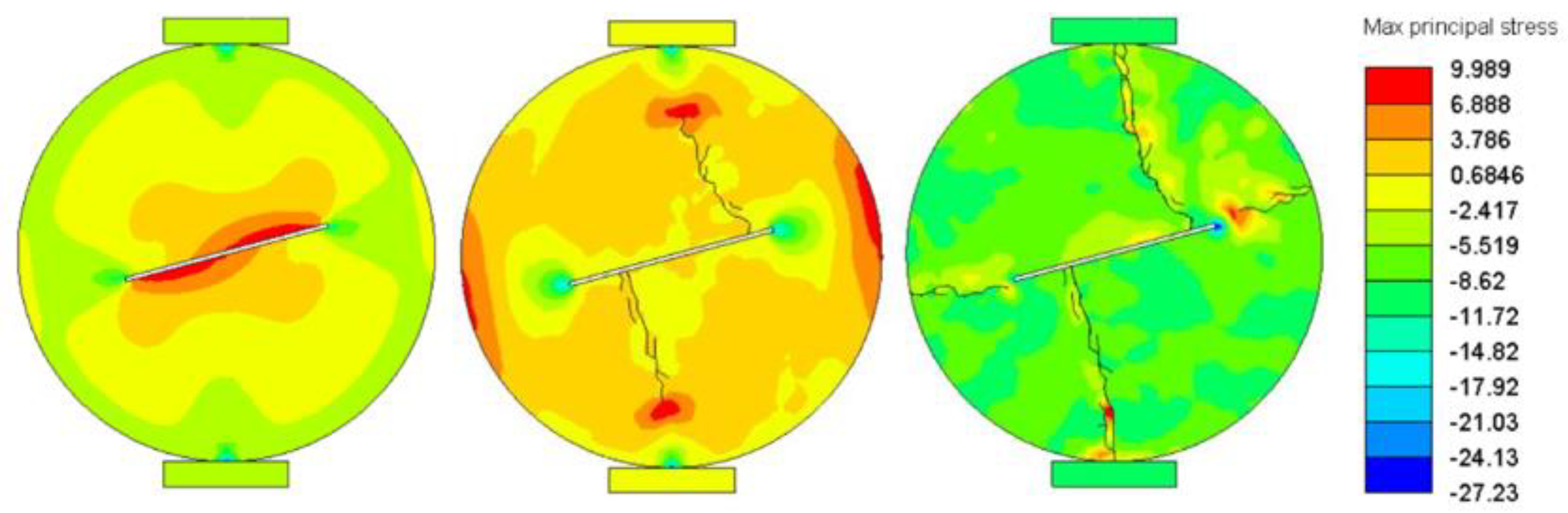
3.3. Stress Field Evolution

Figure 10, Figure 11, Figure 12, Figure 13, Figure 14, Figure 15 and Figure 16 show the evolution of the maximum principal stress field for the Brazilian discs with cracks of different angles. Figure 10 shows the evolution of the maximum principal stress field of the Brazilian disc with the 0° crack. The maximum principal stress is first concentrated at the pre-crack end and increases with the increase in the external load. After crack initiation, the region of maximum principal stress moves to the disc edge along the loading path. Figure 11, Figure 12, Figure 13 and Figure 14 show the evolution of maximum principal stress fields of Brazilian discs with 15°, 30°, 45° and 60° cracks, respectively. The evolution of the maximum principal stress fields of these four types of discs with cracks are similar. The maximum principal stress is first concentrated at the pre-crack end. After crack initiation, the region of maximum principal stress moves with the direction of crack propagation. It is worth noting that before the crack penetrates the disc, the maximum principal stress concentration area is transferred to the disc edge in the direction of the pre-crack.
Figure 15 and Figure 16 show the evolution of maximum principal stress fields of Brazilian discs with 75° and 90° cracks, respectively. When the pre-crack angle is 75°, the maximum principal stress is first concentrated between the pre-crack end and the center. When the pre-crack angle is 90°, the maximum principal stress is first concentrated in the pre-crack center. After crack initiation, the maximum principal stress region moves to the disc edge along the direction of crack propagation. The maximum principal stress concentration region also appears at the disc edge in the direction of the pre-crack. After the initial crack penetrated the disc, the secondary crack originated in the maximum principal stress concentration area on the disc edge, extended to the pre-crack end and penetrated the disc again.

3.4. Plastic Strain Zone

Figure 17, Figure 18, Figure 19, Figure 20, Figure 21, Figure 22 and Figure 23 show the plastic strain evolution for the Brazilian discs with cracks of different angles. Figure 17 shows the plastic strain evolution of the Brazilian disc with the 0° crack. The plastic strain is initiated at the pre-crack end and propagates along the loading path towards the disc end. The crack initiates inside the plastic strain and is less than the length of the plastic strain. The plastic strain zone finally penetrates the disc along the loading direction, which indicates that the damage area of the Brazilian disc with the 0° crack is mainly confined to the loading path.
Figure 18, Figure 19 and Figure 20 show the plastic strain evolution of Brazilian discs with 15°, 30° and 45° cracks, respectively. The plastic strain evolution patterns for these three types of discs with cracks are similar. The plastic strain is initiated at the pre-crack end and propagates towards the loading point at the disc end. The cracks are initiated within the plastic strain and propagate along with the plastic strain. The plastic strain zone eventually reaches the loading point at the disc end and penetrates the disc. The damage area is mainly the area near the macroscopically propagated crack. Figure 21 shows the plastic strain evolution of the Brazilian disc with the 60° crack. The plastic strain is initiated at the pre-crack end and propagates towards the loading point at the disc end. After the initial plastic strain penetrates the disc, the third plastic strain zone is initiated on the left side of the pre-crack, which indicates that when the pre-crack angle is greater than 45°, the damage degree begins to increase.
Figure 22 shows the plastic strain evolution of the Brazilian disc with the 75° crack. The plastic strain initiates from about 3 mm away from the pre-crack tip and propagates towards the loading point at the disc end. After the initial plastic strain penetrates the disc, the third and fourth plastic strain zones are initiated on the left and right sides of the pre-crack and, finally, penetrate the disc, and the damage degree of disc is further increased. Figure 23 shows the plastic strain evolution of the Brazilian disc with the 90° crack. The plastic strain is initiated at the pre-crack center and propagates along the loading path towards the disc end. After the initial plastic strain penetrates the disc from the vertical direction, the third and fourth plastic strain zones are initiated on the left and right sides of the pre-crack and, finally, penetrate the disc from the horizontal direction.

4. Discussion

4.1. Failure Mode Transition

Figure 24 shows the failure mode transition for the Brazilian discs with cracks of different angles, and the crack angles range from 0° and 90°. When the crack angle is between 0° and 45°, the Brazilian disc fails in two halves. When the crack angle is 60°, the Brazilian disc fails in three parts. When the crack angle is 75°, the Brazilian disc fails in four non-uniform sectors. When the crack angle is 90°, the Brazilian disc fails in four uniform sectors. It can be seen that with the increase in the crack angle, the failure of the disc transitions from splitting into two halves to a uniform four-sector failure. The increase in crack angle leads to an increase in the damage degree of the disc. As shown in Figure 25, a similar failure mode transition was observed in Luo’s physical test [38]. In Figure 26, the peak load of disc decreases first and then increases with the increase in crack angle, similar to Figure 2, which indicates that the simulation results in this paper are relatively reliable.

4.2. Effect of Crack Length

In addition to crack angle, the crack length is also an important factor affecting material fracture. Figure 27, Figure 28 and Figure 29 show the failure modes of Brazilian discs with cracks of different lengths and of 0°, 45° and 90° angles, respectively. It can be seen that 0° cracks with different lengths have little effect on the failure mode of Brazilian discs, and the disc always splits into two halves along the loading axis. When the length of a 45° crack is less than 5 mm, the disc splits along the loading axis. When the crack length is greater than 5 mm, the main crack of disc deviates from the loading axis. When the length of a 90° crack is less than 10 mm, the disc splits into two halves along the loading axis. When the crack length is greater than 10 mm, the secondary cracks are generated in the horizontal direction, and the disc is broken into three parts or four uniform sectors.
When the crack length is less than 5 mm, the Brazilian discs with cracks of different angles always split into two half-discs along the loading axis, and the crack angle has little influence on the disc failure mode. When the crack length is greater than 5 mm, the failure modes of Brazilian discs with cracks of different angles are significantly different. Figure 30 shows the peak load of Brazilian discs with cracks of different lengths. It can be seen that the increase in crack length leads to a rapid decrease in the peak load of discs. When the crack length is less than 5 mm, the crack angle has little influence on the peak load of the disc. When the crack length is greater than 5 mm, the crack angle has greater influence on the peak load of the disc, and the peak load of discs with 45° cracks is the smallest.
It can be seen from the above analysis that when the crack length is less than 5 mm, Brazilian discs with cracks of different angles undergo splitting failure along the loading axis. This is consistent with the failure mode of the intact Brazilian disc sample, but the peak load is lower than the peak load of the intact Brazilian disc sample (the crack length is 0). This shows that micro-cracks with different directions in brittle materials such as rocks are one of the reasons for the discreteness of the Brazilian disc test results, although these micro-cracks do not change the final failure mode of the Brazilian disc.

5. Conclusions

The main conclusions are as follows:
(1)
A hybrid finite–discrete element method was used to analyze the Brazilian disc test with cracks of different angles. When the pre-crack angle is between 0° and 60°, the wing crack initiates from the pre-crack end, propagates toward the loading point and penetrates the disc. When the pre-crack angle is 75°, the crack initiation point is about 3 mm from the pre-crack tip. When the pre-crack angle is 90°, the crack starts from the pre-crack center and propagates to the disc end along the loading path. After the crack penetrates the disc, two secondary cracks are generated on the left and right sides of disc and, finally, the disc fails into four uniform sectors;
(2)
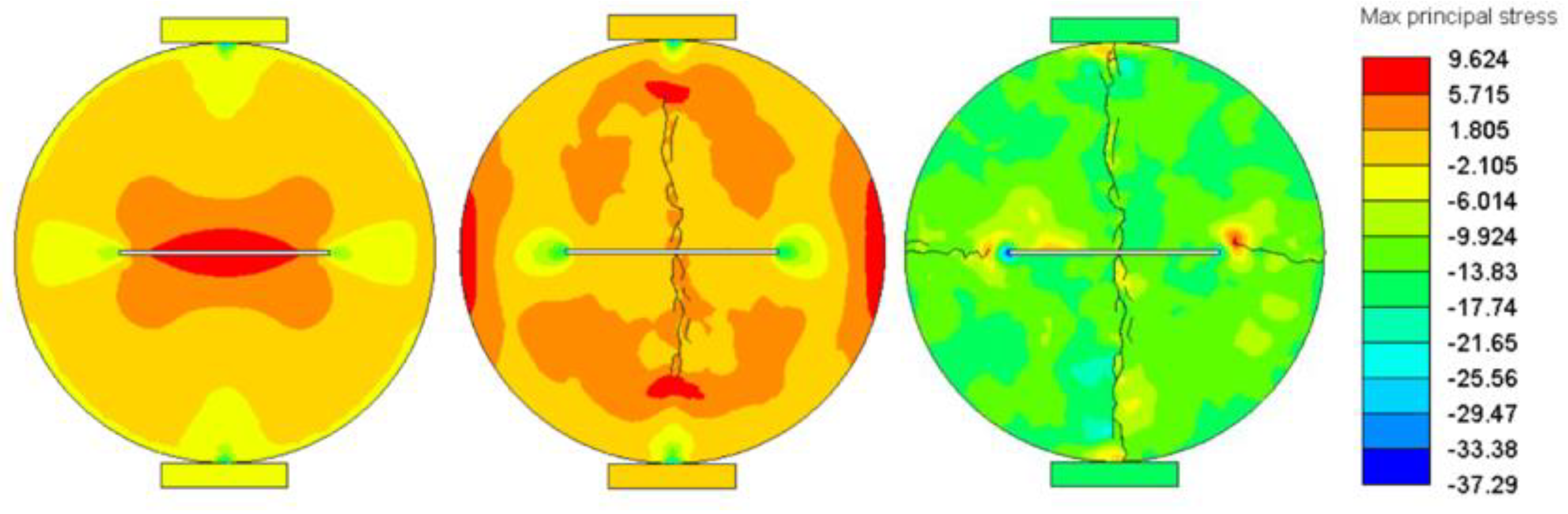
When the angle of the pre-crack is between 0° and 60°, the maximum principal stress is first concentrated at the pre-crack end. After crack initiation, the maximum principal stress region moves toward the loading point with crack propagation. When the pre-crack is at 75°, the maximum principal stress is first concentrated between the pre-crack end and the center. When the pre-crack is at 90°, the maximum principal stress is first concentrated in the crack center. After crack initiation, the maximum principal stress moves to the disc edge along the direction of crack propagation, and the maximum principal stress also appears at the disc edge in the direction of the pre-crack;
(3)
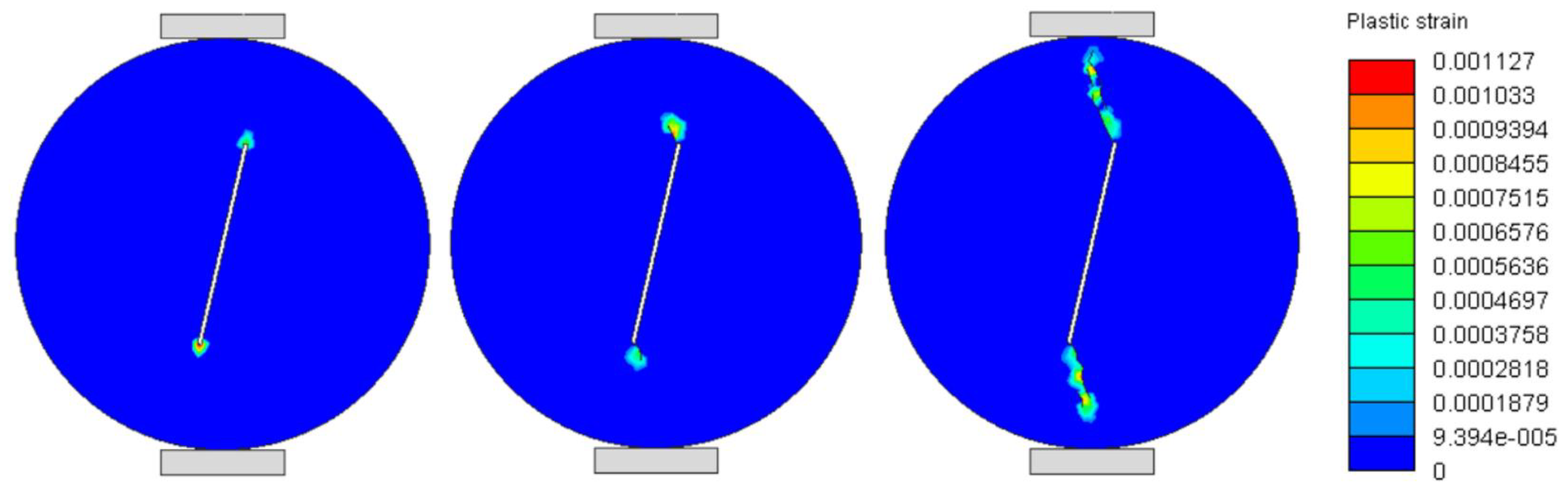
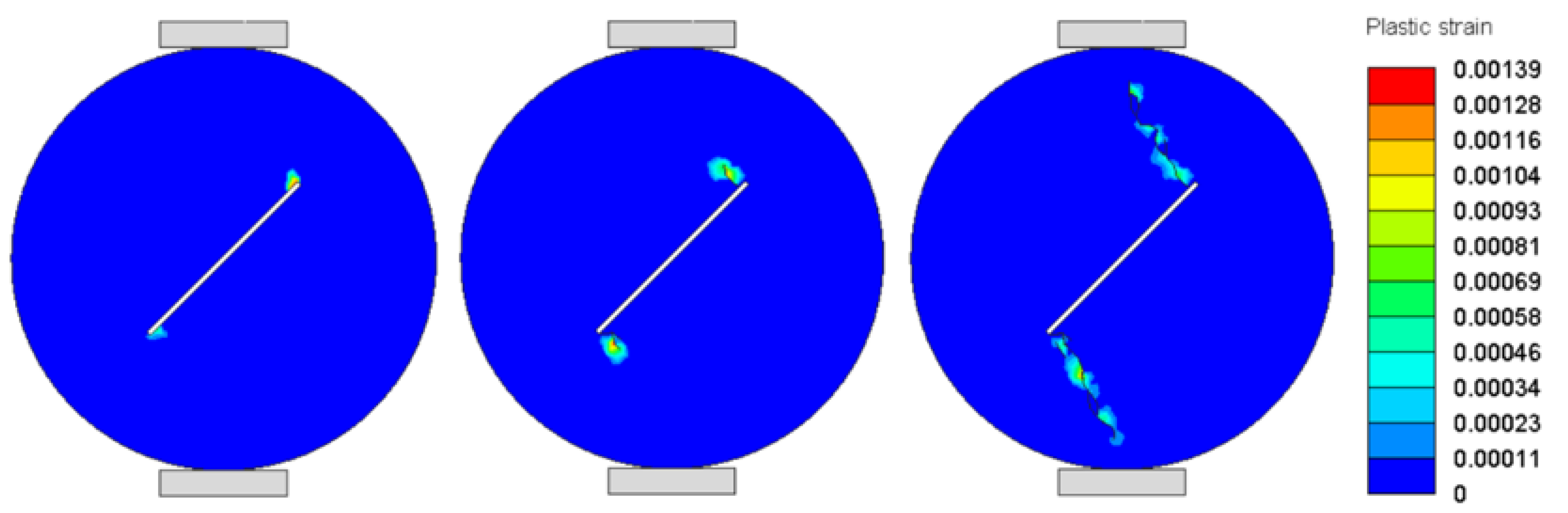
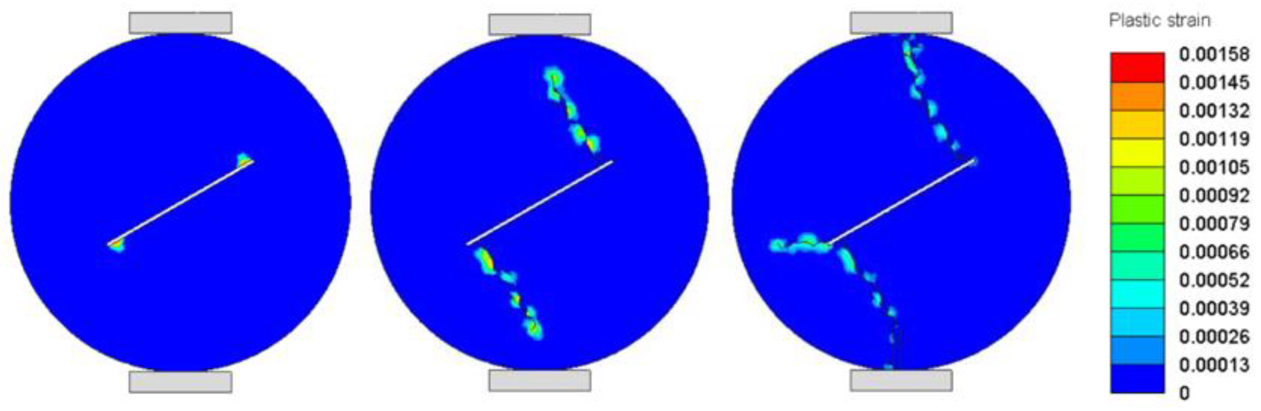
When the angle of the pre-crack is between 0° and 60°, the plastic strain starts at the pre-crack end and propagates towards the loading point. The crack initiates within the plastic strain and propagates with the plastic strain. The damage area is mainly the area near the macroscopically propagated crack. When the pre-crack angle is 75°, the plastic strain initiates from about 3 mm from the pre-crack tip. When the pre-crack angle is 90°, the plastic strain starts from the pre-crack center and propagates to the disc end along the loading axis. After the initial plastic strain penetrates the disc, the third and fourth plastic strain zones are activated and finally penetrate the disc from the horizontal direction;
(4)
The influence of pre-crack length is further studied. When the crack length is less than 5 mm, Brazilian discs with cracks of different angles always split into two half-discs along the loading axis, and the crack angle has little influence on the disc failure mode. When the crack length is larger than 5mm, the crack angle has a great effect on the disc failure mode. The increase in crack length leads to a rapid decrease in the peak load of the disc. When the crack length is less than 5 mm, Brazilian discs with cracks of different angles undergo splitting failure along the loading axis. This is consistent with the failure mode of the intact Brazilian disc sample, but the peak load is lower than that of the intact Brazilian disc sample.

Author Contributions

Conceptualization, X.L.; methodology, X.L.; software, P.X.; validation, P.X., G.Z. and W.Z.; formal analysis, X.L.; funding acquisition, G.Z. All authors have read and agreed to the published version of the manuscript.

Funding

Guoyan Zhao was supported by the State Key Research Development Program of China (No. 2018YFC0604606) and Peng Xiao was supported by the Fundamental Research Funds for the Central Universities of Central South University (No. 2021zzts0278).

Institutional Review Board Statement

Not applicable.

Informed Consent Statement

Not applicable.

Data Availability Statement

The data presented in this study are available on request from the corresponding author.

Conflicts of Interest

The authors declare no conflict of interest.

Appendix A

The influence of mesh size on the load–displacement curves of Brazilian discs with cracks is shown in Figure A1, Figure A2 and Figure A3. Three mesh sizes of 0.8 mm, 1.0 mm and 1.2 mm are considered. The different mesh sizes have a small effect on the load–displacement curves of Brazilian discs with three crack angles and there is a small difference at the peak point. Considering the running speed of the computer and obtaining the detailed fracture process, the 0.8 mm mesh size and a picture output of 6000 were selected in this study.
Figure A1. Load–displacement curves for Brazilian discs with 0° cracks with different mesh sizes.
Mathematics 10 04808 g0a1
Figure A2. Load–displacement curves for Brazilian discs with 45° cracks with different mesh sizes.
Mathematics 10 04808 g0a2
Figure A3. Load–displacement curves for Brazilian discs with 90° cracks with different mesh sizes.
Mathematics 10 04808 g0a3

References

  1. Hao, W.; Dan, M.; Spearing, A.J.S.; Guoyan, Z. Fracture response and mechanisms of brittle rock with different numbers of openings under uniaxial loading. Geomech. Eng. 2021, 25, 481–493. [Google Scholar]
  2. Huo, X.; Shi, X.; Qiu, X.; Chen, H.; Zhou, J.; Zhang, S.; Rao, D. Study on Rock Damage Mechanism for Lateral Blasting under High In Situ Stresses. Appl. Sci. 2021, 11, 4992. [Google Scholar] [CrossRef]
  3. Xiao, P.; Li, D.; Zhao, G.; Liu, M. Experimental and Numerical Analysis of Mode I Fracture Process of Rock by Semi-Circular Bend Specimen. Mathematics 2021, 9, 1769. [Google Scholar] [CrossRef]
  4. Sarfarazi, V.; Haeri, H.; Shemirani, A.B.; Nezamabadi, M.F. A fracture mechanics simulation of the pre-holed concrete Brazilian discs. Struct. Eng. Mech. 2018, 66, 343–351. [Google Scholar]
  5. Zhu, Q.Q.; Li, D.Y.; Han, Z.Y.; Li, X.B.; Zhou, Z.L. Mechanical properties and fracture evolution of sandstone specimens containing different inclusions under uniaxial compression. Int. J. Rock Mech. Min. Sci. 2019, 115, 33–47. [Google Scholar] [CrossRef]
  6. Luo, L.; Li, X.B.; Tao, M.; Dong, L.J. Mechanical behavior of rock-shotcrete interface under static and dynamic tensile loads. Tunn. Undergr. Space Technol. 2017, 65, 215–224. [Google Scholar] [CrossRef]
  7. Xiao, P.; Li, D.; Zhao, G.; Liu, H. New criterion for the spalling failure of deep rock engineering based on energy release. Int. J. Rock Mech. Min. Sci. 2021, 148, 1–12. [Google Scholar] [CrossRef]
  8. ISRM. Suggested methods for determining tensile strength of rock materials. Int. J. Rock Mech. Min. Sci. Geomech. Abstr. 1978, 15, 99–103. [Google Scholar] [CrossRef]
  9. Hondros, G. The evaluation of Poisson’s ratio and the modulus of materials of a low tensile resistance by the Brazilian (indirect tensile) test with particular reference to concrete. Aust. J. Appl. Sci. 1959, 10, 243–268. [Google Scholar]
  10. Akazawa, T. New test method for evaluating internal stress due to compression of concrete: The splitting tension test. J. Jpn. Soc. Civ. Eng. 1943, 29, 777–787. [Google Scholar]
  11. Carneiro, F. A new method to determine the tensile strength of concrete. In Proceedings of the 5th meeting of the Brazilian Association for Technical Rules, 3rd Section, Lisbon, Portugal, 16 September 1943; pp. 126–129. [Google Scholar]
  12. Sgambitterra, E.; Lamuta, C.; Candamano, S.; Pagnotta, L. Brazilian disk test and digital image correlation: A methodology for the mechanical characterization of brittle materials. Mater. Struct. 2018, 51, 19. [Google Scholar] [CrossRef]
  13. Wang, M.; Cao, P. Experimental Study on the Validity and Rationality of Four Brazilian Disc Tests. Geotech. Geol. Eng. 2018, 36, 63–76. [Google Scholar] [CrossRef]
  14. Markides, C.F.; Kourkoulis, S.K. The Stress Field in a Standardized Brazilian Disc: The Influence of the Loading Type Acting on the Actual Contact Length. Rock Mech. Rock Eng. 2012, 45, 145–158. [Google Scholar] [CrossRef]
  15. Dan, D.Q.; Konietzky, H.; Herbst, M. Brazilian tensile strength tests on some anisotropic rocks. Int. J. Rock Mech. Min. Sci. 2013, 58, 1–7. [Google Scholar] [CrossRef]
  16. Stirling, R.A.; Simpson, D.J.; Davie, C.T. The application of digital image correlation to Brazilian testing of sandstone. Int. J. Rock Mech. Min. Sci. 2013, 60, 1–11. [Google Scholar] [CrossRef] [Green Version]
  17. Yu, Y.; Zhang, J.X.; Zhang, J.C. A modified Brazilian disk tension test. Int. J. Rock Mech. Min. Sci. 2009, 46, 421–425. [Google Scholar] [CrossRef]
  18. Markides, C.F.; Pazis, D.N.; Kourkoulis, S.K. Closed full-field solutions for stresses and displacements in the Brazilian disk under distributed radial load. Int. J. Rock Mech. Min. Sci. 2010, 47, 227–237. [Google Scholar] [CrossRef]
  19. Erarslan, N.; Liang, Z.Z.; Williams, D.J. Experimental and Numerical Studies on Determination of Indirect Tensile Strength of Rocks. Rock Mech. Rock Eng. 2012, 45, 739–751. [Google Scholar] [CrossRef]
  20. Hudson, J.; Brown, E.; Rummel, F. The controlled failure of rock discs and rings loaded in diametral compression. Int. J. Rock Mech. Min. Sci. Geomech. Abstr. 1972, 9, 241–248. [Google Scholar] [CrossRef]
  21. Swab, J.J.; Yu, J.; Gamble, R.; Kilczewski, S. Analysis of the diametral compression method for determining the tensile strength of transparent magnesium aluminate spinel. Int. J. Fract. 2011, 172, 187–192. [Google Scholar] [CrossRef]
  22. Li, D.; Wong, L.N.Y. The Brazilian Disc Test for Rock Mechanics Applications: Review and New Insights. Rock Mech. Rock Eng. 2013, 46, 269–287. [Google Scholar] [CrossRef]
  23. Li, D.; Li, B.; Han, Z.; Zhu, Q. Evaluation on Rock Tensile Failure of the Brazilian Discs under Different Loading Configurations by Digital Image Correlation. Appl. Sci. 2020, 10, 5513. [Google Scholar] [CrossRef]
  24. Bai, T.; Pollard, D.D.; Gao, H. Explanation far fracture spacing in layered materials. Nature 2000, 403, 753–756. [Google Scholar] [CrossRef] [PubMed]
  25. Yi, D.K.; Xiao, Z.M.; Tan, S.K. On the Plastic Zone Size and the Crack Tip Opening Displacement of an Interface Crack Between two Dissimilar Materials. Int. J. Fract. 2012, 176, 97–104. [Google Scholar] [CrossRef]
  26. Li, Z.C.; Li, L.C.; Li, M.; Zhang, L.Y.; Zhang, Z.L.; Huang, B.; Tang, C.A. A numerical investigation on the effects of rock brittleness on the hydraulic fractures in the shale reservoir. J. Nat. Gas Sci. Eng. 2018, 50, 22–32. [Google Scholar] [CrossRef]
  27. Alneasan, M.; Behnia, M.; Bagherpour, R. Analytical investigations of interface crack growth between two dissimilar rock layers under compression and tension. Eng. Geol. 2019, 259, 105188. [Google Scholar] [CrossRef]
  28. Li, T.J.; Li, L.C.; Tang, C.A.; Zhang, Z.L.; Li, M.; Zhang, L.Y.; Li, A.S. A coupled hydraulic-mechanical-damage geotechnical model for simulation of fracture propagation in geological media during hydraulic fracturing. J. Pet. Sci. Eng. 2019, 173, 1390–1416. [Google Scholar] [CrossRef]
  29. Sarfarazi, V.; Haeri, H.; Ebneabbasi, P.; Bagheri, K. Simulation of the tensile behaviour of layered anisotropy rocks consisting internal notch. Struct. Eng. Mech. 2019, 69, 51–67. [Google Scholar]
  30. Yang, S.; Huang, Y.H.; Tian, W.L.; Zhu, J.B. An experimental investigation on strength, deformation and crack evolution behavior of sandstone containing two oval flaws under uniaxial compression. Eng. Geol. 2017, 217, 35–48. [Google Scholar] [CrossRef]
  31. Xiao, P.; Li, D.; Zhao, G.; Zhu, Q.; Liu, H.; Zhang, C. Mechanical properties and failure behavior of rock with different flaw inclinations under coupled static and dynamic loads. J. Cent. South Univ. 2020, 27, 2945–2958. [Google Scholar] [CrossRef]
  32. Zhu, Q.; Li, D.; Li, X.; Han, Z.; Ma, J. Mixed mode fracture parameters and fracture characteristics of diorite using cracked straight through Brazilian disc specimen. Theor. Appl. Fract. Mech. 2022, 123, 103682. [Google Scholar] [CrossRef]
  33. Wong, L.N.Y.; Einstein, H.H. Crack Coalescence in Molded Gypsum and Carrara Marble: Part 1. Macroscopic Observations and Interpretation. Rock Mech. Rock Eng. 2009, 42, 475–511. [Google Scholar] [CrossRef]
  34. Xibing, L.; Tao, Z.; Diyuan, L. Dynamic Strength and Fracturing Behavior of Single-Flawed Prismatic Marble Specimens Under Impact Loading with a Split-Hopkinson Pressure Bar. Rock Mech. Rock Eng. 2017, 50, 16. [Google Scholar]
  35. Banks-Sills, L.; Schwartz, J. Fracture testing of Brazilian disk sandwich specimens. Int. J. Fract. 2002, 118, 191–209. [Google Scholar] [CrossRef]
  36. Tong, J.; Wong, K.Y.; Lupton, C. Determination of interfacial fracture toughness of bone-cement interface using sandwich Brazilian disks. Eng. Fract. Mech. 2007, 74, 1904–1916. [Google Scholar] [CrossRef] [Green Version]
  37. Banks-Sills, L. 50th Anniversary Article: Review on Interface Fracture and Delamination of Composites. Strain 2014, 50, 98–110. [Google Scholar] [CrossRef]
  38. Luo, L.; Li, X.B.; Qiu, J.D.; Zhu, Q.Q. Study on Fracture Initiation and Propagation in a Brazilian Disc with a Preexisting Crack by Digital Image Correlation Method. Adv. Mater. Sci. Eng. 2017, 2017, 2493921. [Google Scholar] [CrossRef] [Green Version]
  39. Haeri, H.; Sarfarazi, V.; Zhu, Z.M.; Moradizadeh, M. The effect of ball size on the hollow center cracked disc (HCCD) in Brazilian test. Comput. Concr. 2018, 22, 373–381. [Google Scholar]
  40. Chang, X.; Guo, T.F.; Zhang, S. Cracking behaviours of layered specimen with an interface crack in Brazilian tests. Eng. Fract. Mech. 2020, 228, 106904. [Google Scholar] [CrossRef]
  41. Yin, T.B.; Zhang, S.S.; Li, X.B.; Bai, L. A numerical estimate method of dynamic fracture initiation toughness of rock under high temperature. Eng. Fract. Mech. 2018, 204, 87–102. [Google Scholar] [CrossRef]
  42. Yin, T.B.; Wu, Y.; Wang, C.; Zhuang, D.D.; Wu, B.Q. Mixed -mode I plus II tensile fracture analysis of thermally treated granite using straight -through notch Brazilian disc specimens. Eng. Fract. Mech. 2020, 234, 107111. [Google Scholar] [CrossRef]
  43. Li, C.; Gao, M.Z.; Lu, Y.Q.; Liu, Q.; He, Z.Q.; Peng, G.Y. Effect of prefabricated crack width on stress intensity factors of Brazilian disc sample with center crack. In Proceedings of the 2nd International Conference on Geo-Mechanics, Geo-Energy and Geo-Resources (IC3G), Chengdu, China, 22–24 September 2018; pp. 335–342. [Google Scholar]
  44. Haeri, H.; Khaloo, A.; Marji, M.F. Experimental and numerical analysis of Brazilian discs with multiple parallel cracks. Arab. J. Geosci. 2015, 8, 5897–5908. [Google Scholar] [CrossRef]
  45. Hamdi, P.; Stead, D.; Elmo, D. Damage characterization during laboratory strength testing: A 3D-finite-discrete element approach. Comput. Geotech. 2014, 60, 33–46. [Google Scholar] [CrossRef]
  46. Cai, M.; Kaiser, P.K. Numerical simulation of the Brazilian test and the tensile strength of anisotropic rocks and rocks with pre-existing cracks. Int. J. Rock Mech. Min. Sci. 2004, 41, 450–451. [Google Scholar] [CrossRef]
  47. Mahabadi, O.K.; Cottrell, B.E.; Grasselli, G. An Example of Realistic Modelling of Rock Dynamics Problems: FEM/DEM Simulation of Dynamic Brazilian Test on Barre Granite. Rock Mech. Rock Eng. 2010, 43, 707–716. [Google Scholar] [CrossRef]
  48. Feng, F.; Li, X.; Rostami, J.; Li, D. Modeling hard rock failure induced by structural planes around deep circular tunnels. Eng. Fract. Mech. 2019, 205, 152–174. [Google Scholar] [CrossRef]
  49. Mitelman, A.; Elmo, D. Analysis of tunnel support design to withstand spalling induced by blasting. Tunn. Undergr. Space Technol. 2016, 51, 354–361. [Google Scholar] [CrossRef]
  50. Li, X.; Feng, F.; Li, D. Numerical simulation of rock failure under static and dynamic loading by splitting test of circular ring. Eng Fract Mech 2018, 188, 184–201. [Google Scholar] [CrossRef]
  51. Feng, F.; Li, X.; Luo, L.; Zhao, X.; Chen, S.; Jiang, N.; Huang, W.; Wang, Y. Rockburst response in hard rock owing to excavation unloading of twin tunnels at great depth. Bull. Eng. Geol. Environ. 2021, 80, 7613–7631. [Google Scholar] [CrossRef]
  52. Xiao, P.; Zhao, G.; Liu, H. Failure Transition and Validity of Brazilian Disc Test under Different Loading Configurations: A Numerical Study. Mathematics 2022, 10, 2681. [Google Scholar] [CrossRef]
  53. Cai, M. Influence of intermediate principal stress on rock fracturing and strength near excavation boundaries—Insight from numerical modeling. Int. J. Rock Mech. Min. Sci. 2008, 45, 763–772. [Google Scholar] [CrossRef]
  54. Cai, M. Fracture Initiation and Propagation in a Brazilian Disc with a Plane Interface: A Numerical Study. Rock Mech. Rock Eng. 2013, 46, 289–302. [Google Scholar] [CrossRef]
Figure 1. Seven Brazilian disc models with cracks of different angles. The crack angles are 0°, 15°, 30°, 45°, 60°, 75°and 90°, respectively.
Mathematics 10 04808 g001
Figure 2. Load–displacement curves for the Brazilian discs with cracks of different angles. (a) The crack angle is between 0° and 45°; (b) crack angle is between 45° and 90°.
Mathematics 10 04808 g002
Figure 3. Fracture process for Brazilian disc with a crack of 0° angle.
Mathematics 10 04808 g003
Figure 4. Fracture process for Brazilian disc with a crack of 15° angle.
Mathematics 10 04808 g004
Figure 5. Fracture process for Brazilian disc with a crack of 30° angle.
Mathematics 10 04808 g005
Figure 6. Fracture process for Brazilian disc with a crack of 45° angle.
Mathematics 10 04808 g006
Figure 7. Fracture process for Brazilian disc with a crack of 60° angle.
Mathematics 10 04808 g007
Figure 8. Fracture process for Brazilian disc with a crack of 75° angle.
Mathematics 10 04808 g008
Figure 9. Fracture process for Brazilian disc with a crack of 90° angle.
Mathematics 10 04808 g009
Figure 10. Evolution of maximum principal stress for Brazilian disc with crack of 0° angle.
Mathematics 10 04808 g010
Figure 11. Evolution of maximum principal stress for Brazilian disc with crack of 15° angle.
Mathematics 10 04808 g011
Figure 12. Evolution of maximum principal stress for Brazilian disc with crack of 30° angle.
Mathematics 10 04808 g012
Figure 13. Evolution of maximum principal stress for Brazilian disc with crack of 45° angle.
Mathematics 10 04808 g013
Figure 14. Evolution of maximum principal stress for Brazilian disc with crack of 60° angle.
Mathematics 10 04808 g014
Figure 15. Evolution of maximum principal stress for Brazilian disc with crack of 75° angle.
Mathematics 10 04808 g015
Figure 16. Evolution of maximum principal stress for Brazilian disc with crack of 90° angle.
Mathematics 10 04808 g016
Figure 17. Plastic strain evolution for Brazilian disc with a crack of 0° angle.
Mathematics 10 04808 g017
Figure 18. Plastic strain evolution for Brazilian disc with a crack of 15° angle.
Mathematics 10 04808 g018
Figure 19. Plastic strain evolution for Brazilian disc with a crack of 30° angle.
Mathematics 10 04808 g019
Figure 20. Plastic strain evolution for Brazilian disc with a crack of 45° angle.
Mathematics 10 04808 g020
Figure 21. Plastic strain evolution for Brazilian disc with a crack of 60° angle.
Mathematics 10 04808 g021
Figure 22. Plastic strain evolution for Brazilian disc with a crack of 75° angle.
Mathematics 10 04808 g022
Figure 23. Plastic strain evolution for Brazilian disc with a crack of 90° angle.
Mathematics 10 04808 g023
Figure 24. The failure mode transition for Brazilian discs with cracks of different angles.
Mathematics 10 04808 g024
Figure 25. The failure mode for Brazilian discs with cracks of different angles in Luo’s research [38]; the crack angles are 36°, 54°and 72°, respectively.
Mathematics 10 04808 g025
Figure 26. The load–displacement curves for the Brazilian discs with cracks of different angles in Luo’s research [38].
Mathematics 10 04808 g026
Figure 27. The failure mode for Brazilian discs with 0° cracks of different length. The crack lengths are 2 mm, 5 mm, 10 mm, 15 mm and 20 mm, respectively.
Mathematics 10 04808 g027
Figure 28. The failure mode for Brazilian discs with 45° cracks of different length. The crack lengths are 2 mm, 5 mm, 10 mm, 15 mm and 20 mm, respectively.
Mathematics 10 04808 g028
Figure 29. The failure mode for Brazilian discs with 90° cracks of different length. The crack lengths are 2 mm, 5 mm, 10 mm, 15 mm and 20 mm, respectively.
Mathematics 10 04808 g029
Figure 30. The peak load for Brazilian discs with cracks of different length. The crack angles are 0°, 45°, and 90°, respectively.
Mathematics 10 04808 g030
Table 1. Material property of model.
Mechanical ParametersBrazilian DiscLoading Platen
Young’s modulus (E, GPa)43.2211.00
Poisson’s ratio (ν)0.230.29
Shear modulus (G, GPa)17.5-
Density (ρ, Ns2/mm4)2.81 × 1097.84 × 109
Cohesion (c, MPa)51-
Friction angle ( φ )28°-
Tensile strength ( σ t , MPa)12.8-
Fracture energy (Gf, N/mm)0.01-
Normal penalty (Pn, N/mm2)43,200211,000
Tangential penalty (Pt, N/mm2)432021,100
Friction (γ)0.10.1
Mesh element size (mm)0.80.8
Publisher’s Note: MDPI stays neutral with regard to jurisdictional claims in published maps and institutional affiliations.

