Article

Thermoelastic Coupling Response of an Unbounded Solid with a Cylindrical Cavity Due to a Moving Heat Source

by
Ashraf M. Zenkour
1,2,*,
Daoud S. Mashat
1 and
Ashraf M. Allehaibi
1,3
1
Department of Mathematics, Faculty of Science, King Abdulaziz University, P.O. Box 80203, Jeddah 21589, Saudi Arabia
2
Department of Mathematics, Faculty of Science, Kafrelsheikh University, Kafrelsheikh 33516, Egypt
3
Department of Mathematics, Jamoum University College, Umm Al-Qura University, Jamoum, Makkah 21955, Saudi Arabia
*
Author to whom correspondence should be addressed.
Mathematics 2022, 10(1), 9; https://doi.org/10.3390/math10010009
Submission received: 27 November 2021 / Revised: 9 December 2021 / Accepted: 17 December 2021 / Published: 21 December 2021
(This article belongs to the Topic Artificial Intelligence (AI) Applied in Civil Engineering)

Abstract

:
The current article introduces the thermoelastic coupled response of an unbounded solid with a cylindrical hole under a traveling heat source and harmonically altering heat. A refined dual-phase-lag thermoelasticity theory is used for this purpose. A generalized thermoelastic coupled solution is developed by using Laplace’s transforms technique. Field quantities are graphically displayed and discussed to illustrate the effects of heat source, phase-lag parameters, and the angular frequency of thermal vibration on the field quantities. Some comparisons are made with and without the inclusion of a moving heat source. The outcomes described here using the refined dual-phase-lag thermoelasticity theory are the most accurate and are provided as benchmarks for other researchers.

1. Introduction

The thermoelasticity theory is adopted in various applications to obtain interesting formulations due to a variety of microphysical processes. The starting point of the classical coupled thermoelasticity (CTE) model was founded by Duhamel [1]. While Biot [2] formulated the CTE theory by considering the second law of thermodynamics. One of the first generalized theories is established by Lord and Shulman (L–S) [3] by including a thermal relaxation parameter. While Green and Lindsay [4] developed another generalized model by including two thermal relaxation parameters. Such generalized theories with one or more thermal relaxation parameters are also stated as hyperbolic thermoelasticity theories [5]. Green and Nagdhi (G–N) [6,7,8] formulated three various theories of thermoelasticity in an unusual way. In addition, Tzou [9,10] presented a modern generalized one which is called a dual-phase-lag (DPL) theory. A lot of research is presented to include and modify Tzou’s model (see, e.g., [11,12,13,14,15]).
Many problems found in the literature are concerned with the thermoelastic response of unbounded bodies with cylindrical cavities. Chandrasekharaiah and Srinath [16] applied the G–N II model to analyze axisymmetric thermoelastic communications in an unbounded solid including a cylindrical hole. Allam et al. [17] discussed thermal distribution field quantities of a half-space containing a circular cylindrical cavity in the framework of a G–N model. Ezzat and El-Bary [18,19] used a fractional-order of both thermo-viscoelasticity and magneto-thermoelasticity theories to deal with an unbounded perfect conducting media having a cylindrical hole in the existence of an axial uniform magnetic field. Sharma et al. [20] tried to solve the dynamic formulation of an elasto-thermo-diffusion infinite cylindrical hole under various boundary conditions. Kumar and Mukhopadhyay [21] presented the impacts of three-phase-lags (TPLs) on thermoelastic communications under step input in temperature on a cylindrical hole in an infinite body. Mukhopadhyay and Kumar [22] dealt with the thermoelastic communications in an infinite solid with a cylindrical hole based on a two-temperature L–S model. Kumar et al. [23] described the thermoelastic communications based on a hyperbolic two-temperature L–S model in an unbounded body including a cylindrical hole. Sarkar and Mondal [24] examined transient behavior in a two-temperature model in an infinite body with a cylindrical hole under a time-dependent moving heat source.
A lot of infinite bodies having cylindrical cavities may be exposed to either continuous heat source, ramp-type heating effect, or thermal shock. Sharma et al. [25] considered one-dimensional elasto-thermo-diffusive communications in an infinite solid containing a cylindrical hole under the action of a continuous heat source utilizing the L–S theory. Mukhopadhyay and Kumar [26] analyzed the thermoelastic communications in a medium having a cylindrical hole under a ramp-type heating effect using various models. Xia et al. [27] used the L–S model to develop a generalized thermoelastic diffusion theory for the dynamic response of an unbounded body having a cylindrical hole and its surface undergoing a thermal shock. In addition, Xiong and Tian [28] discussed the thermoelastic analysis of an unbounded medium with a cylindrical hole whose surface undergoes time-dependent thermal shock due to G–N II and III theories.
Some interesting problems are concerned with thermoelastic communications in elastic infinite media with cylindrical holes and subjected to moving heat sources. Abouelregal [29] obtained the induced fields in such an unbounded body having a cylindrical hole under a traveling heat source and harmonically varying heat based on the dual-phase-lag theory. Youssef [30] presented the analysis of thermoelastic communications in an elastic infinite body with a cylindrical cavity a moving heat source with a uniform velocity that thermally shocked at the bounding surface. Youssef [31] used the G–N II theory to develop a two-temperature model for an infinite medium having constant elastic parameters. Shaw and Mukhopadhyay [32] presented thermoelastic communications in a micro-stretched body in the existence of a traveling heat source. Sarkar and Lahiri [33] solved a 1D problem for a thermoelastic infinite medium under a moving plane of heat source. Youssef [34] presented a two-temperature fractional-order theory for an infinite medium. Xia et al. [35] studied a semi-infinite medium under a traveling heat source by utilizing the finite element method in the time domain in the context of the L–S model. Abbas [36] solved the problem of thermoelastic communication in a clamped microscale beam under a moving heat source based on G–N III theory. Youssef [37] discussed the thermoelastic communications in an unbounded solid having a cylindrical hole in the existence of moving heat sources utilizing the L–S model.
In this paper, the problem of an unbounded solid containing a cylindrical cavity is studied. The governing equations are carried out based on the refined dual-phase-lag (RDPL) thermoelasticity theory. The general solution gained is utilized to a certain problem once the bounding plane of the cavity is exposed to a traveling heat source. The inverse Laplace transforms is calculated numerically to obtain the field quantities. Some comparisons will be tabulated and shown graphically to study the benefit of different theories and estimate the effect of different parameters.

2. Fundamental Equations

Let us discuss a thermoelastic coupling response of an unbounded solid containing a cylindrical hole due to a traveling heat source using a unified dual-phase-lag theory. The cylindrical coordinates system ( r , φ , z ) is selected to deal with such a problem in which z -axis is sitting alongside the axis of the cylindrical cavity.
The displacement vector u of the present, an axially symmetric cylindrical cavity is summarized as
u r = u r , t , u φ = u z = 0 .
The strains can be expressed as
e r r = u r ,           e φ φ = u r ,           e = e r r + e φ φ = 1 r r r u .
The dynamic equation in the non-existence of body force is stated as
2 μ + λ 2 u u r 2 γ θ r = ρ 2 u t 2 ,
where 2 is the Laplacian operator. It satisfies the formula
2 * = 1 r r r * r .
The constitutive equations for the coupled thermoelastic solid with omitting the volume forces can be stated as
σ r r = 2 μ u r + σ z z , σ φ φ = 2 μ u r + σ z z , σ z z = λ e γ θ , σ z r = σ r φ = σ φ z = 0 .
The heat conduction equation in the refined form is represented by
k L θ 2 θ = L q ρ C e θ t + γ T 0 e t Q ,
where L θ and L q are higher-order time derivative operators given by
L θ = 1 + n = 1 N τ θ n n ! n t n , L q = ϱ + n = 1 N τ q n n ! n t n ,
which represents one of the modified coupled forms of the heat transport equation presented in [38,39,40,41]. The above equation represents the more general when N has some +ve integers larger than zero. Different particular cases can be considered along with Equation (6) as follows:
(i)
Coupled dynamical thermoelasticity (CTE theory) [2]: τ θ = τ q = 0 and ϱ = 1
k 2 θ = ρ C e θ t + γ T 0 e t Q .
(ii)
Lord and Shulman generalized thermoelasticity theory (L–S theory) [3]: τ θ = 0 , τ q = τ 0 and ϱ = 1
k 2 θ = 1 + τ q t ρ C e θ t + γ T 0 e t Q .
(iii)
Green and Naghdi generalized thermoelasticity theory (G–N theory) without energy dissipation [6,7,8]: τ θ = 0 , τ q = 1 , N = 1 , ϱ = 0 , and k k *
k * 2 θ = t ρ C e θ t + γ T 0 e t Q .
(iv)
Simple generalized thermoelasticity theory with dual-phase-lag (SDPL theory) [12,13,14,15]: τ q τ θ > 0 , N = 1 and ϱ = 1
k 1 + τ θ t 2 θ = 1 + τ q t ρ C e θ t + γ T 0 e t Q .
(v)
Refined generalized thermoelasticity theory with dual-phase-lag (RDPL theory) [12,13,14,15]: τ q τ θ > 0 , N > 1 and ϱ = 1 ,
k 1 + n = 1 N τ θ n n ! n t n 2 θ = 1 + n = 1 N τ q n n ! n t n ρ C e θ t + γ T 0 e t Q .

3. Problem Construction

It is appropriate to introduce the following non-dimensional variables in the next sections:
r , u = c 0 η r , u , t , τ θ , τ q = η c 0 2 t , τ θ , τ q ,   σ i i = σ i i γ T 0 , θ = θ T 0 , c 0 2 = λ + 2 μ ρ ,           η = ρ C e k ,
and setting Q = Q / k T 0 c 0 2 η 2 . All governing equations, with the directions above dimensionless variables, are lowered to (dropping the dashed for suitability)
σ r r = c 1 u r + σ z z ,
σ φ φ = c 1 u r + σ z z ,
σ z z = c 2 e θ ,
2 u u r 2 1 c 3 θ r = 2 u t 2 ,
2 L θ L q t θ ε L q e t = L q Q ,
where
c 1 = 2 μ γ T 0 ,           c 2 = λ γ T 0 ,           c 3 = λ + 2 μ γ T 0 = c 1 + c 2 ,           ε = γ ρ C e .
The heat source is shifting along the radial direction with a uniform velocity ϑ , which be able to be defined by the formula
Q = Q 0 δ r ϑ t .

4. Closed-Form Solution

The complete solutions will be given by solving Equations (17) and (18) to get firstly the temperature θ and the dilatation e . Then, the corresponding displacement and stresses can be given in terms of temperature and dilatation. For this purpose, we utilize the following initial conditions:
u r , 0 = u t t = 0 = 0 ,           θ r , 0 = θ t t = 0 = 0 ,             R r < .
We supply the above homogenous initial conditions by additional boundary conditions. The present medium will be considered as inactive and the surface of the cylindrical cavity under harmonically varying heat and traction free. These conditions are defined as
  • The surface of the cylindrical cavity is exposed to a harmonically varying heat
R , t = θ 0 H t cos ω t ,             t > 0 .
  • The mechanical boundary condition is considered as the surface of the cylindrical cavity is traction free
σ r r R , t = 0 .
It is to be noted that when the angular frequency of thermal vibration ω 0 , the problem tends to be a thermal shock one. In addition to the above initial and boundary conditions, we take into account the following regularity conditions
u r , t = 0 ,           θ r , t = 0 ,             r .
Laplace transform is taken for Equations (20)–(23), under the homogeneous initial conditions that appeared in Equation (28), one gets:
σ ¯ r r = c 1 d u ¯ d r + σ ¯ z z ,
σ ¯ φ φ = c 1 u ¯ r + σ ¯ z z ,
σ ¯ z z = c 2 e ¯ θ ¯ .
Taking the discrepancy of both sides of Equation (24) then one gets
c 3 2 s 2 e ¯ 2 θ ¯ = 0 ,
while the other governing equation of heat conduction became
2 s ϖ 0 θ ¯ ε s ϖ 0 e ¯ = ϖ 1 e s ϑ r ,
where
ϖ 0 = L ¯ q L ¯ θ ,           ϖ 1 = Q 0 ϑ ϖ 0 ,           L ¯ θ = 1 + n = 1 N τ θ n n ! s n ,           L ¯ q = ϱ + n = 1 N τ q n n ! s n .
The equations occurred in Equations (36)–(38) be able to be identified in a fourth-order ordinary non-homogenous differential equation in the dilatation e ¯ as in the form
4 β 1 2 + β 0 e ¯ r = g r ,
where
g r = ϖ 2 s ϑ r e s ϑ r ,
and the coefficients β i are given by
β 0 = s 3 ϖ 0 , β 1 = s s + ϖ 3 , ϖ 2 = ϖ 1 s C 3 ϑ 2 , ϖ 3 = ϖ 0 1 + ε c 3 .
Equation (31) is extremely complicated since it is done in a polar coordinate system. It can be re-considered as
2 ζ 1 2 2 ζ 2 2 e ¯ r = g r ,
where ζ j 2 are the roots of the equation
ζ 4 β 1 ζ 2 + β 0 = 0 .
These roots ζ j are given respectively by
ζ 1 , 2 2 = 1 2 β 1 ± β 1 2 4 β 0   .
Equation (34) represents the next modified Bessel’s equation of zero-order
1 r r r r ζ 1 2 1 r r r r ζ 2 2 e ¯ r = g r ,  
which gets a solution underneath the regularity conditions: u ¯ , θ ¯ 0 as r . So, the general solution of e ¯ is represented by
e ¯ r = j = 1 2 B j K 0 ζ j r + e ¯ p ,  
where B j are integration parameters, K 0 ζ j r is modified Bessel’s function of the first kind, and e ¯ p is a particular solution. It is provided by
e ¯ p = K 0 ζ 2 r g r K 0 ζ 1 r W r d r K 0 ζ 1 r g r K 0 ζ 2 r W r d r ,  
in which W r is the Wronskian
W r = ζ 1 K 0 ζ 2 r K 1 ζ 1 r ζ 2 K 0 ζ 1 r K 1 ζ 2 r .
Using the solution of e ¯ in Equation (39), one gets the solution of θ ¯ as
θ ¯ = c 3 j = 1 2 ζ ˇ j B j K 0 ζ j r + θ ¯ p ,
where
ζ ˇ j = 1 s 2 ζ j 2 ,           θ ¯ p = e ¯ p s 2 u ¯ p d r ,           u ¯ p = 1 r r e ¯ p d r .
The radial displacement be able to be stated for the regularity condition u ¯ 0 as r from the formula
e ¯ r = D u ¯ r ,           D = d d r + 1 r ,
in the form
u ¯ r = j = 1 2 1 ζ j B j K 1 ζ j r + u ¯ p ,
where u ¯ p is already given in Equation (42).
At this point, the solution is finished. It is sufficient to decide the two parameters B j from the boundary conditions offered in Equations (22) and (23). Then, it is simple to carry out the stresses in terms of radial displacement and temperature. According to Equations (25)–(27), the stresses may be given in Laplace state as
σ ¯ 1 = j = 1 2 c 3 1 ζ ˇ j K 0 ζ j r + c 1 ζ j r K 1 ζ j r B j + c 1 d u ¯ p d r + c 2 e ¯ p c 3 θ ¯ p ,
σ ¯ 2 = j = 1 2 c 2 c 3 ζ ˇ j K 0 ζ j r c 1 ζ j r K 1 ζ j r B j + c 1 u ¯ p r + c 2 e ¯ p c 3 θ ¯ p ,
σ ¯ 3 = j = 1 2 c 2 c 3 ζ ˇ j K 0 ζ j r B j + c 2 e ¯ p c 3 θ ¯ p .
So, the current analytical solution is previously given for the RDPL theory in the Laplace domain. To complete the solution in the physical domain we should consider the function f t as an inversion of the Laplace transform f ¯ s as
f t = e q t t 1 2 f ¯ q + Re l = 1 L 1 l f ¯ q + i l π t   ,
where q is a random constant, Re denotes the real part, i implies the imaginary quantity unit and L implies a suitably huge integer. For quicker combination, numerous numerical analyses have shown that the evaluation of q satisfies the connection q t 4.7 [35]. Utilizing the numerical technique mentioned, to reverse the statements of temperature θ , radial displacement u , dilatation e , radial stress σ 1 , hoop stress σ 2 , and axial stress σ 3 .

5. Validation of Results

Several presentations will be offered to put into recommendation the impact of numerous models on the variable quantities. The material properties of the unbounded body having a cylindrical hole due to a traveling heat source are identified according to the following values of parameters:
λ = 7.76 × 10 10   N   m 2 ,   μ = 3.86 × 10 10   N   m 2 ,   k = 386   W   m 1   K 1 ,
ρ = 8954   kg   m 3 ,   α t = 1.78 × 10 5   K 1
C e = 383.1   J   kg 1   K 1 ,   T 0 = 293   K ,   k * = 1.2   W   m 1   K 1 .
Numerical results are obtained (except otherwise stated) for θ 0 = 10 , Q 0 = 1 , ϑ = 17 , ω = 20 , τ q = 0.02 , τ θ = 0.018 , t = 0.03 , and the inner radius R = 1 .

5.1. First Validation Example

Results of the field quantities due to different thermoelasticity theories with dual-phase-lag are reported in Table 1 and Table 2 at the position r = 1.2 . The impact of the velocity of heat source ϑ on all field variables of different thermoelasticity theories with are presented at dimensionless time t = 0.03 , and for two values of the angular frequency of thermal vibration ω = 0 (Table 1) and ω = 20 (Table 2). Additional outcomes of variable quantities are outlined in Figure 1, Figure 2, Figure 3, Figure 4, Figure 5, Figure 6, Figure 7, Figure 8, Figure 9, Figure 10, Figure 11, Figure 12, Figure 13, Figure 14, Figure 15, Figure 16, Figure 17, Figure 18, Figure 19, Figure 20, Figure 21, Figure 22, Figure 23 and Figure 24 across the radial direction of an unbounded body with a cylindrical hole.
The outcomes described in Table 1 and Table 2 will be provided as benchmarks for other researchers. It is established from these tables that:
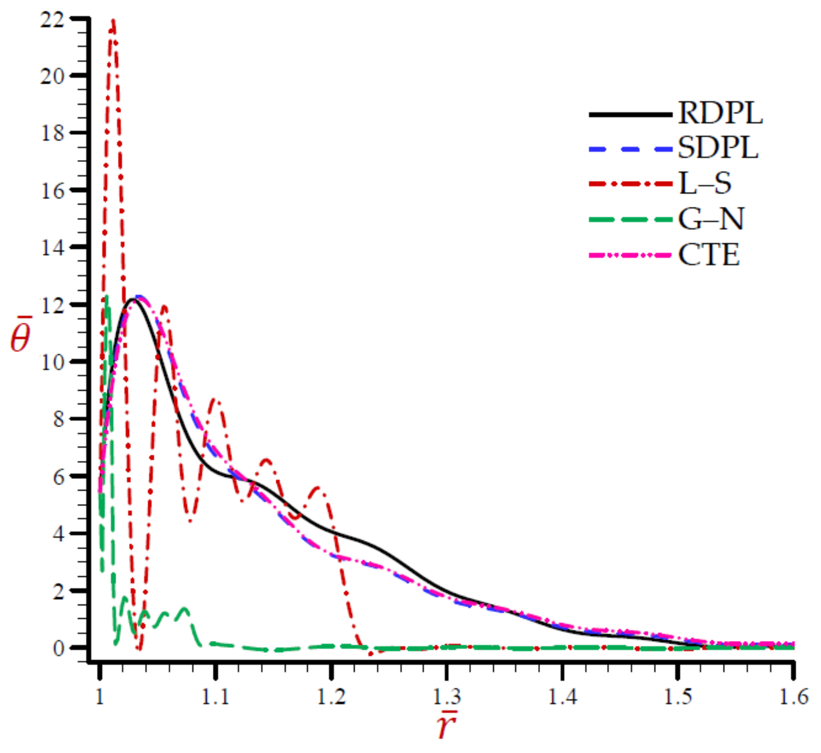
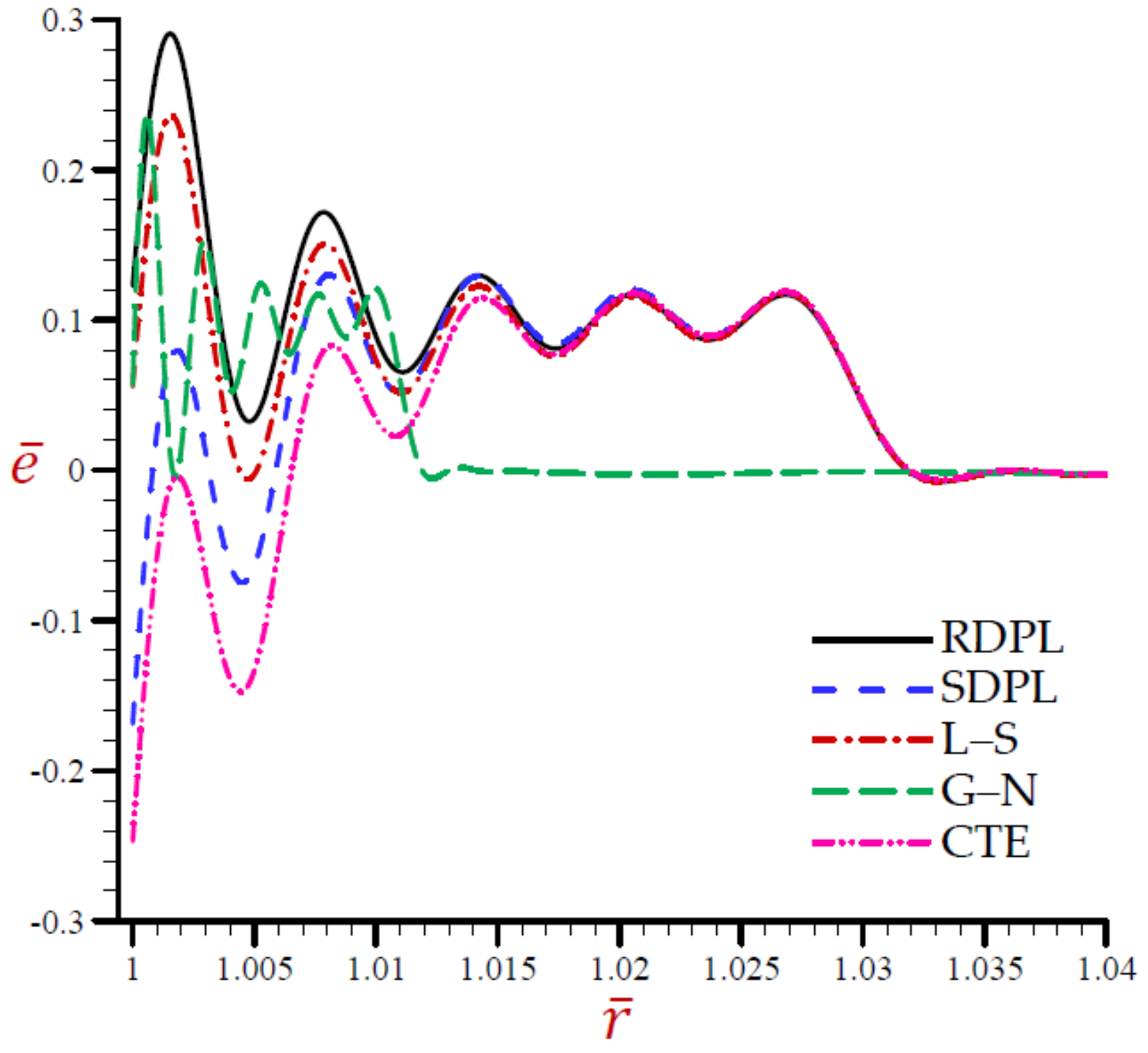
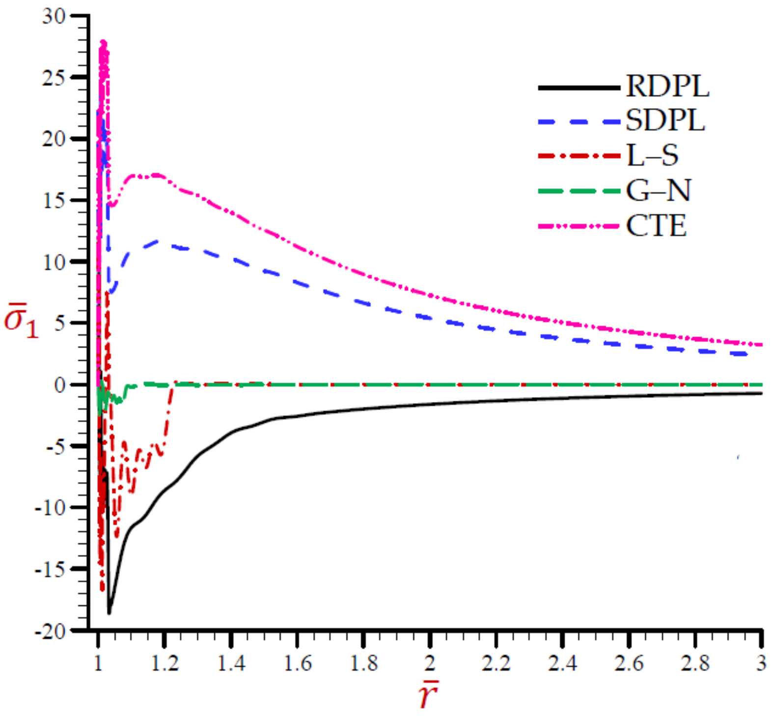
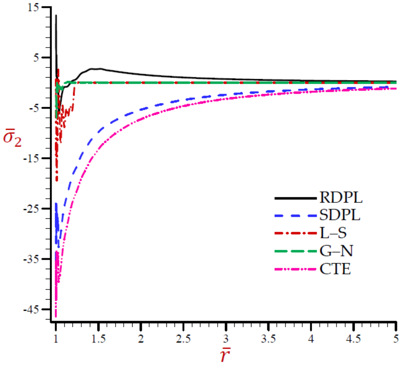
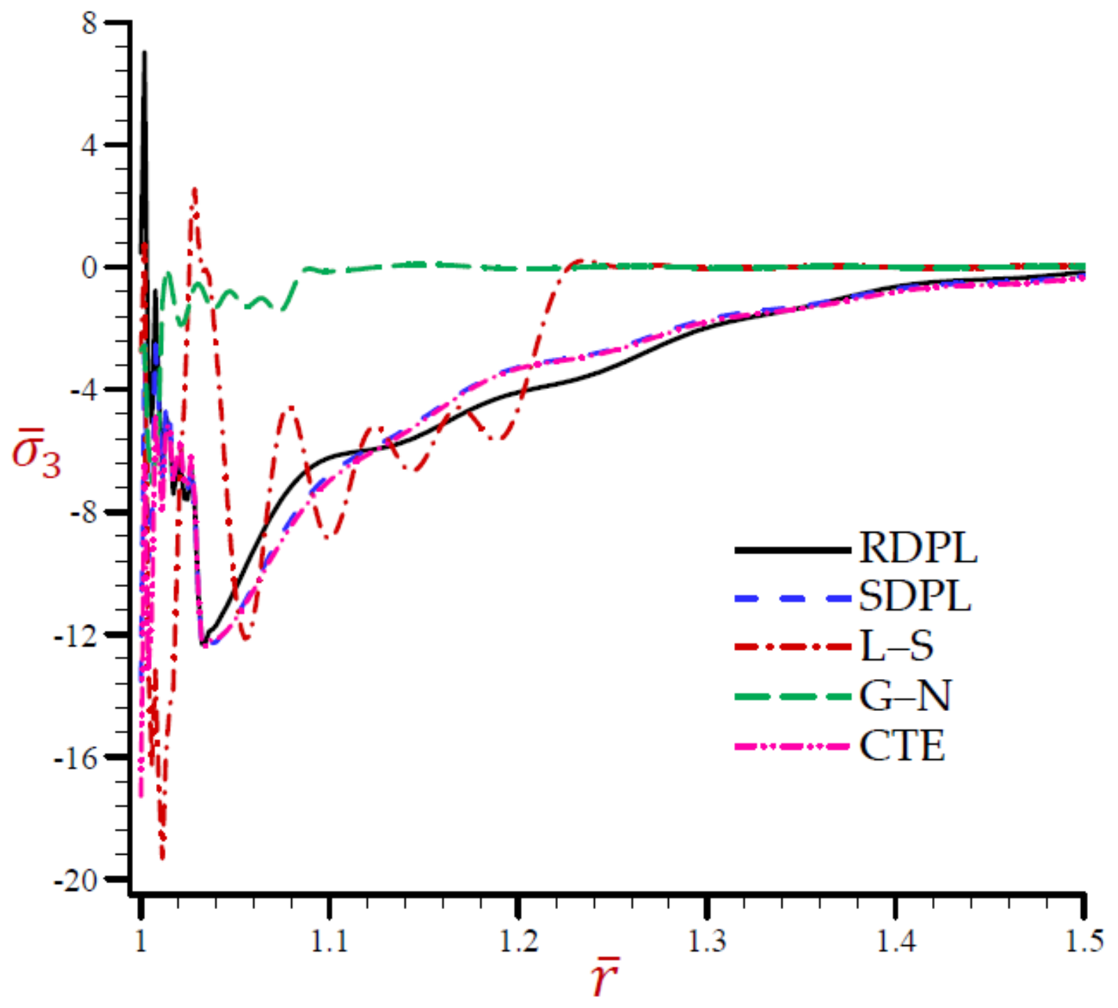
  • The G–N theory gives the smallest absolute field of all field quantities.
  • The other theories CTE and L–S give suitable results for the field quantities.
  • Three values N = 3 , 4, and 5 have been used for the RDPL theory while the simple dual-phase-lag (SDPL) theory is described with N = 1 .
  • The most accurate results are given by using the RDPL theory.
  • For the RDPL theory the temperature, displacement, and hoop stress are slightly increasing with the increase in many terms N , while the dilatation, radial stress, and axial stress are slightly decreasing. The increasing and decreasing amounts may be un-sensitive when N 5 .

5.2. Second Validation Example

Now, Figure 1, Figure 2, Figure 3, Figure 4, Figure 5 and Figure 6 show the impact of all theories on the field quantities with fixed time t = 0.03 , velocity of heat source ϑ = 17 , and angular frequency of thermal vibration ω = 20 . The rest of the figures are presented based on the refined dual-phase-lag (RDPL) theory with N = 5 to investigate the influence of different parameters on the field quantities.
The variation of the temperature θ ¯ across the radial direction of the cylindrical cavity according to all theories is presented in Figure 1. Similar graphs of the rest of the field quantities are produced in Figure 2, Figure 3, Figure 4, Figure 5 and Figure 6. Figure 1 shows that the temperature CTE, L–S, and the SDPL theories vibrate around the path of the RDPL theory. In addition, the G–N theory vibrates around the path of the RDPL theory, but in a small range. The temperature of the G–N theory may early vanish than the other theories. Figure 2 shows that the dilatation e ¯ of CTE, L–S, G–N, and SDPL theories vibrate around the path of the RDPL theory. Figure 3 shows that the radial displacements u ¯ of the L–S and G–N theories may vanish during the radial direction. The radial displacements of the CTE theory are the lowest ones while those of the RDPL theory are the biggest ones. The displacement of all theories may vanish as r increases. Figure 4 shows that the radial stress σ ¯ 1 of the L–S and G–N theories may vanish during the radial direction when r > 1.2 . The radial stresses of the RDPL theory are the lowest ones while those of the CTE theory are the greatest ones. The radial stresses of all theories may vanish as r increases. Figure 5 shows that the hoop stress σ ¯ 2 of the L–S and G–N theories may vanish during the radial direction when r > 1.3 . The hoop stresses of the CTE theory are the smallest ones while those of the RDPL theory are the greatest ones. The hoop stresses of all theories may vanish as r increases. Finally, Figure 6 shows that the axial stress σ ¯ 3 of CTE, L–S, and the SDPL theories vibrate around the path of the RDPL theory. In addition, the G–N theory vibrates around the path of the RDPL theory, but in a small range. The axial stress of the G–N theory may early vanish than the other theories. It is concluded from Figure 1, Figure 2, Figure 3, Figure 4, Figure 5 and Figure 6 that the outcomes of the RDPL theory are the most truthful.

5.3. Additional Applications

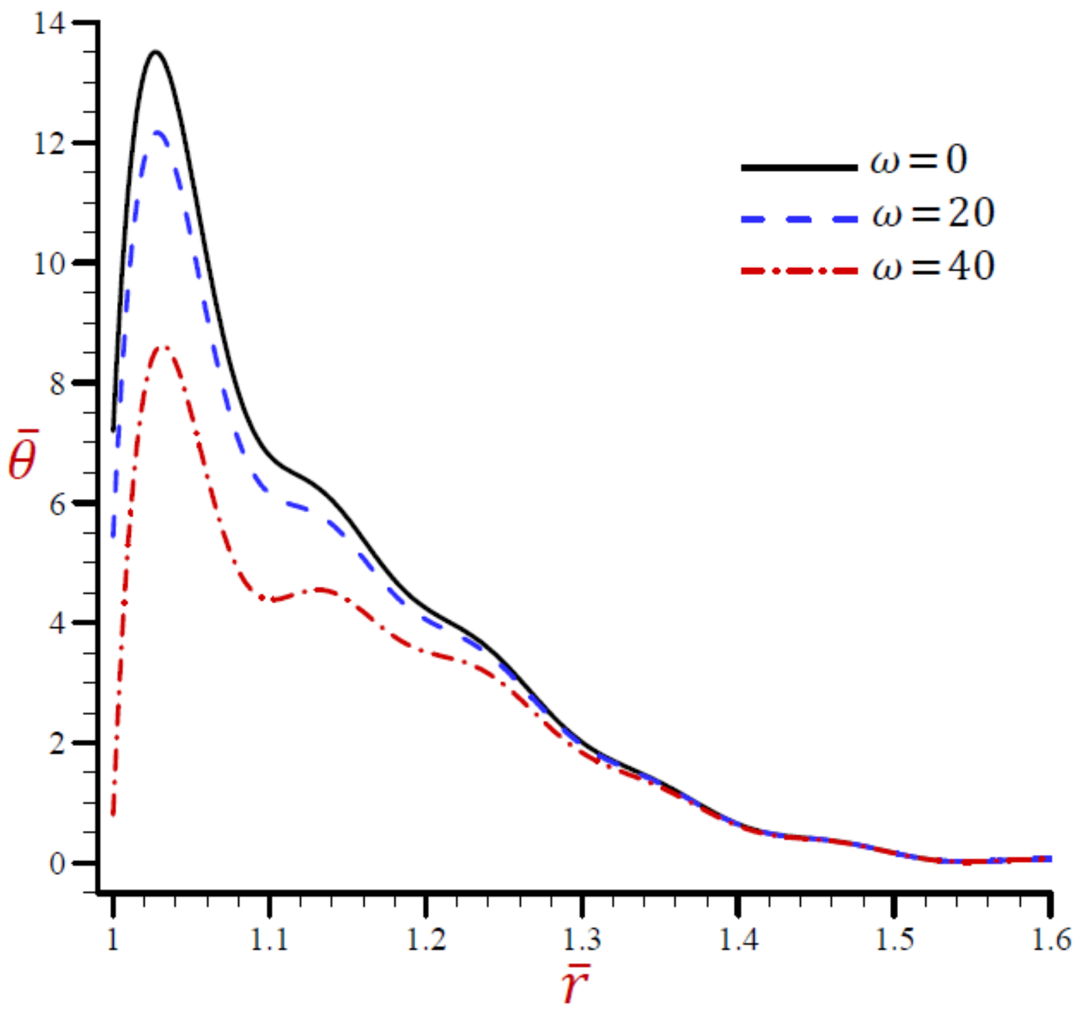
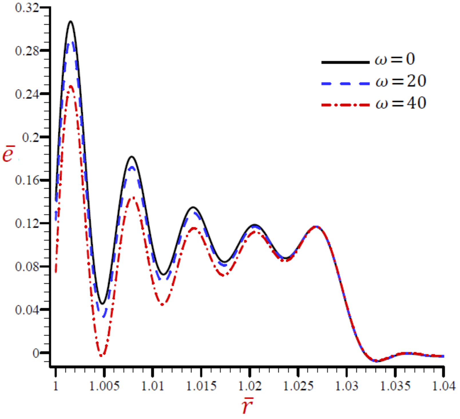
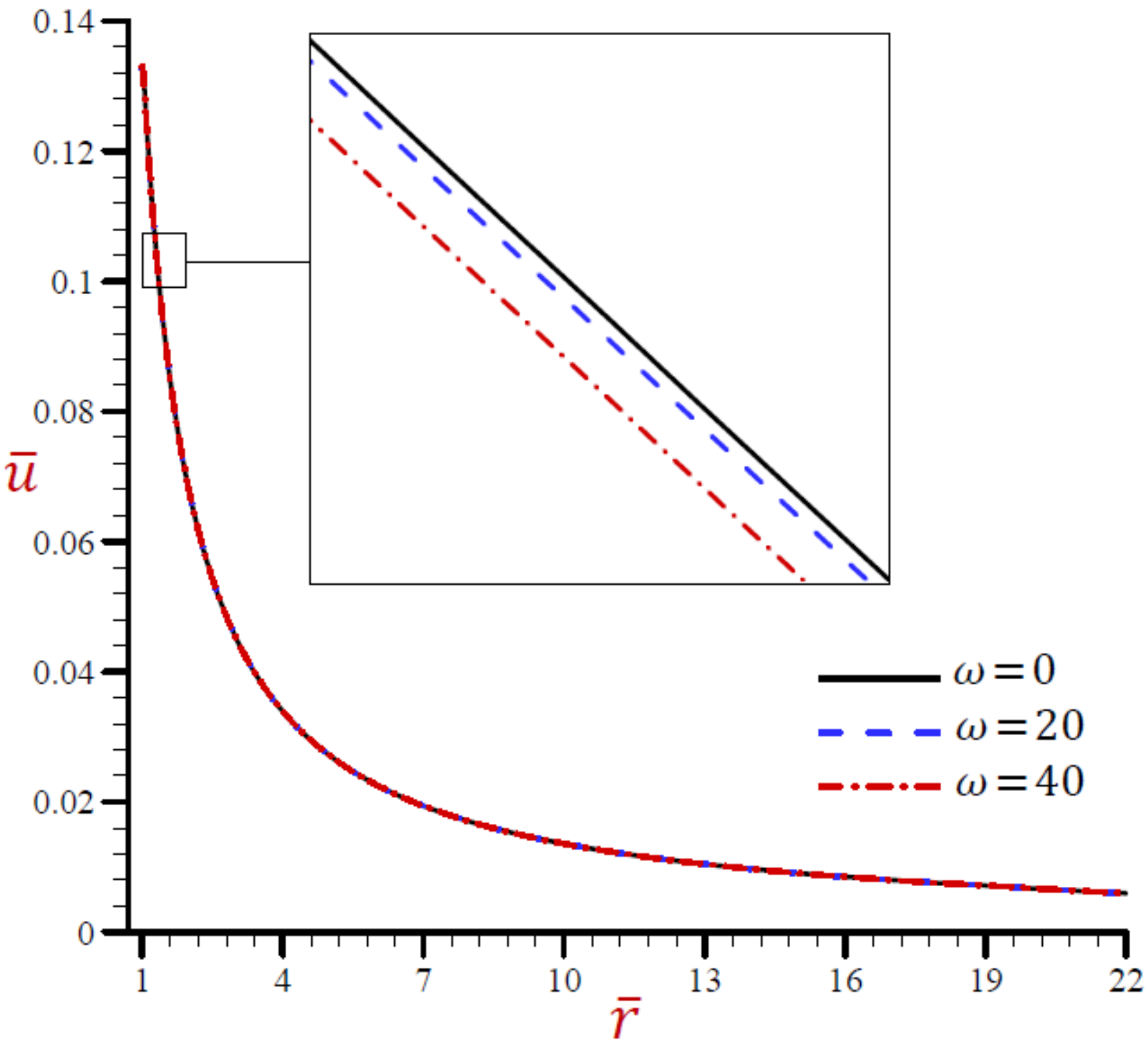
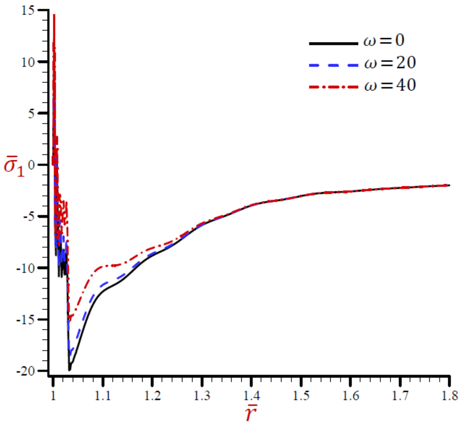
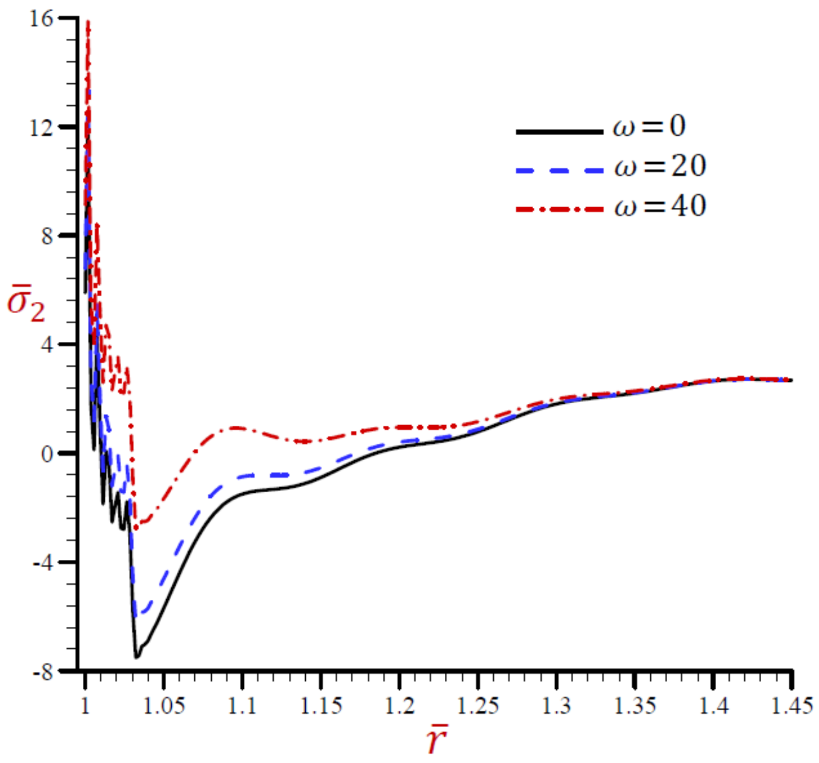
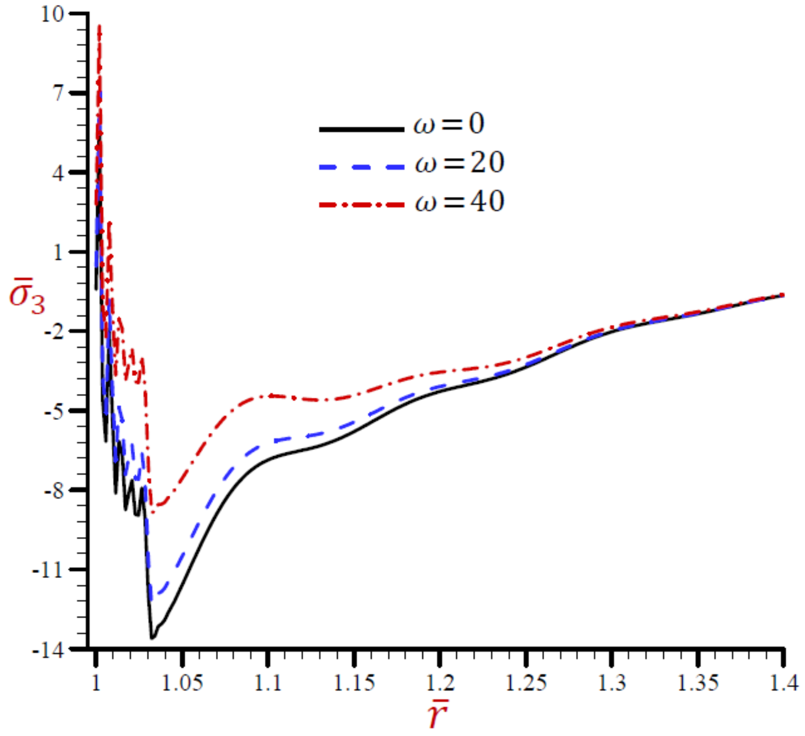
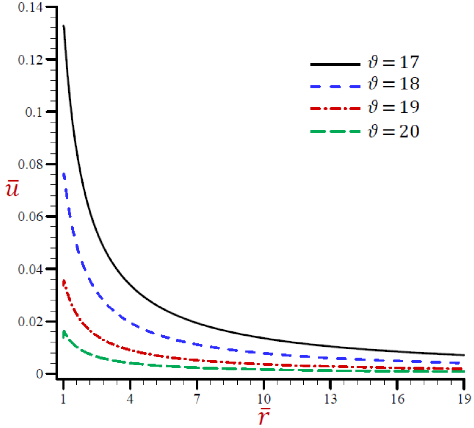
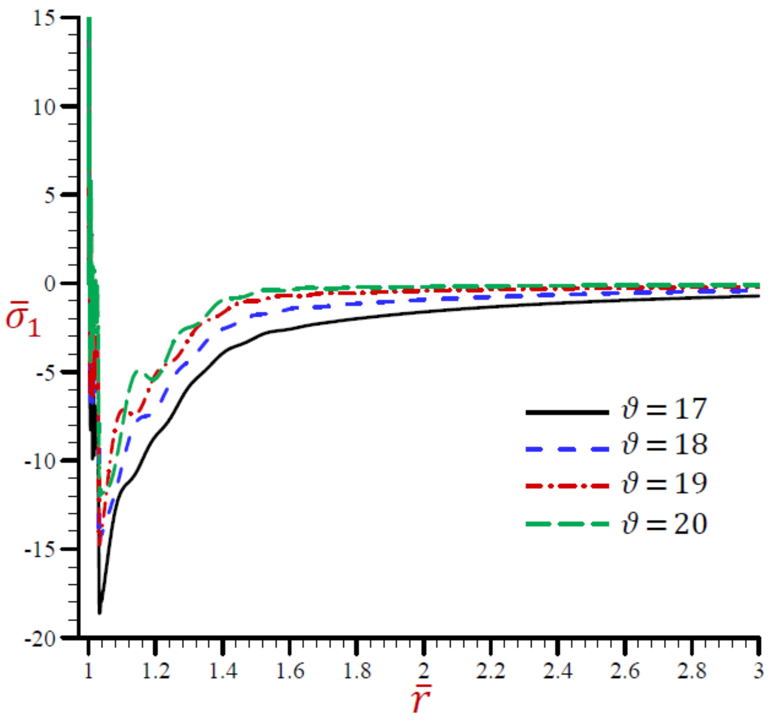
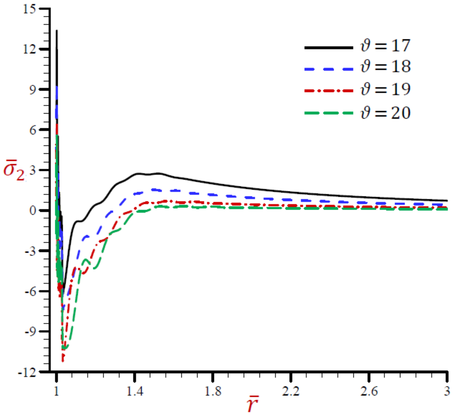
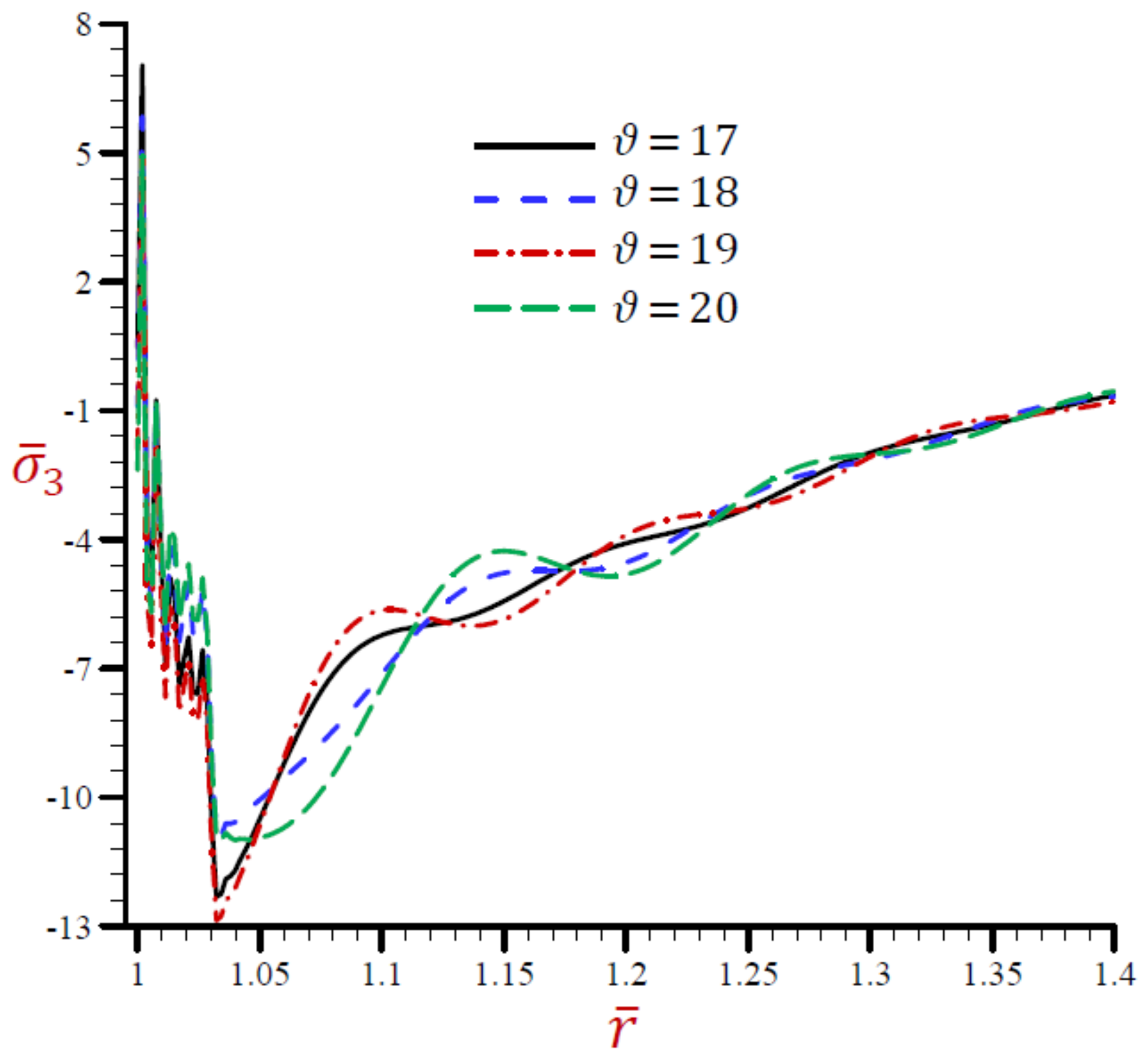
5.3.1. Effect of Angular Frequency of Thermal Vibration

Now, we discuss the impact of the angular frequency of thermal vibration ω on the field quantities using the RDPL theory. Figure 7 shows the impact of ω on the temperature θ ¯ along the radial direction of the cylindrical cavity. Similar graphs of the rest of the field quantities are presented in Figure 8, Figure 9, Figure 10, Figure 11 and Figure 12. It is clear in Figure 7 that the temperature increases as ω decreases. The temperature vanishes as r increases irrespective of the value of ω . Figure 8 shows that the dilatation e ¯ vibrates across the radial direction of the cylindrical cavity. The wave magnitude increases as ω decreases. The radial displacement u ¯ directly decreases along the radial directional of the cylindrical cavity in Figure 9. It is clear that at a fixed position u ¯ increases as ω decreases.
The radial stress σ ¯ 1 across the radial direction of the cylindrical cavity due to the RDPL theory is drawn in Figure 10. The radial stress σ ¯ 1 is rabidly vibrating across the radial direction in a small range 1 r < 1.035 . The radial stress σ ¯ 1 is increasing with the increase in ω when 1.035 r < 1.3 . After that the values of σ ¯ 1 are coincident to vanish as r increases. Once again, the hoop σ ¯ 2 and axial σ ¯ 3 stresses along the radial direction of the cylindrical using the RDPL theory are plotted in similar graphs of the radial stress σ ¯ 1 in Figure 11 and Figure 12. Both hoop and axial stresses are rabidly vibrating along the radial direction in a small range 1 r < 1.03 . The hoop and axial stresses increase as ω increases when 1.03 r < 1.45 . After that the values of σ ¯ 2 and σ ¯ 3 are coincident to vanish as r increases.

5.3.2. Effect of Velocity of Heat Source

The effects of the velocity of heat source ϑ on all field variables based upon the RDPL theory are presented in Figure 13, Figure 14, Figure 15, Figure 16, Figure 17 and Figure 18. Figure 13 shows the effect of ϑ on the temperature θ ¯ across the radial direction of the cylindrical cavity. Similar graphs of the rest of the field quantities are presented in Figure 14, Figure 15, Figure 16, Figure 17 and Figure 18. It is clear in Figure 13 that the temperature θ ¯ vibrates across the radial direction for different values of the velocity of heat source ϑ . The temperature vanishes as r increases and this irrespective of the value of ϑ . Figure 14 shows that the dilatation e ¯ vibrates across the radial direction of the cylindrical cavity. The wave magnitude increases as ϑ decreases. The radial displacement u ¯ directly decreases along the radial directional of the cylindrical cavity in Figure 15. It is clear that at a fixed position u ¯ increases as ϑ decreases.
The radial stress σ ¯ 1 across the radial direction of the cylindrical cavity using the RDPL theory is drawn in Figure 16 for distinct values of ϑ . The radial stress σ ¯ 1 is rabidly vibrating increases the radial direction in a small range 1 r < 1.05 . The radial stress σ ¯ 1 increases as ϑ increases when r 1.05 . The values of σ ¯ 1 are coincident to vanish as r increases. Once again, the hoop σ ¯ 2 and axial σ ¯ 3 stresses along the radial direction of the cylindrical using the RDPL theory are plotted in similar graphs of the radial stress σ ¯ 1 in Figure 11 and Figure 12. Both hoop and axial stresses are rabidly vibrating along the radial direction in a small range 1 r < 1.03 . The hoop and radial stresses increase as ω increases when 1.03 r < 1.45 . After that the values of σ ¯ 2 and σ ¯ 3 are coincident to vanish as r increases. In addition, the hoop stress σ ¯ 3 across the radial direction of the cylindrical using the RDPL theory is plotted for different ϑ in similar graphs of the radial stress σ ¯ 1 in Figure 17. The hoop stress is rabidly vibrating along the radial direction in a small range 1 r < 1.05 . It increases as ϑ decreases when r 1.05 . For large values of r the values of σ ¯ 2 will be coincident and maybe vanished. However, the axial stresses σ ¯ 3 is drawn across the radial direction of the cylindrical using the RDPL theory for distinct values of ϑ in Figure 18. The axial stress is rabidly vibrating along the radial direction in a small range 1 r < 1.032 while it slowly vibrating after that in a large range 1.032 r < 1.4 . For large values of r the values of σ ¯ 3 will be coincident and maybe vanished.

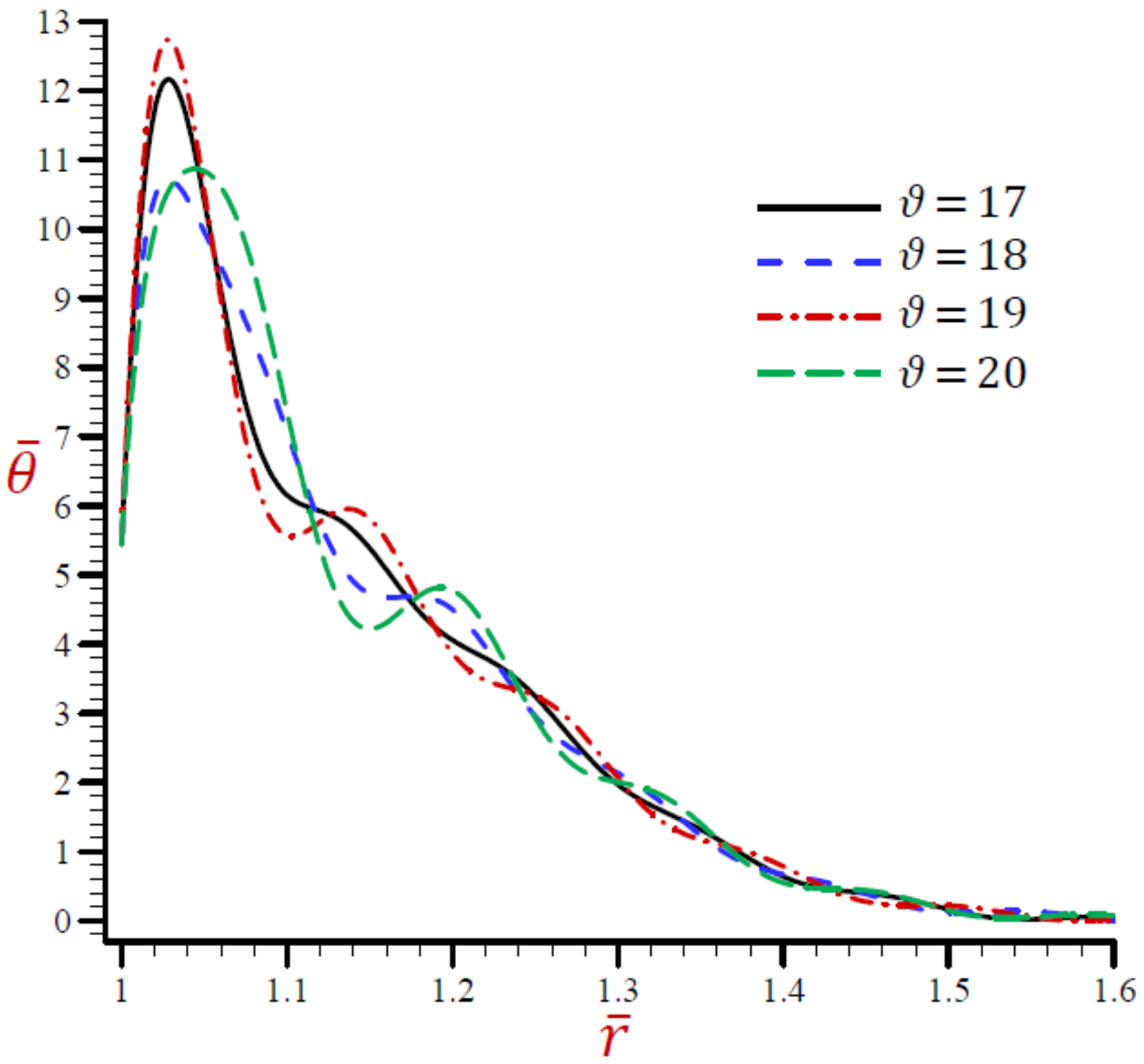
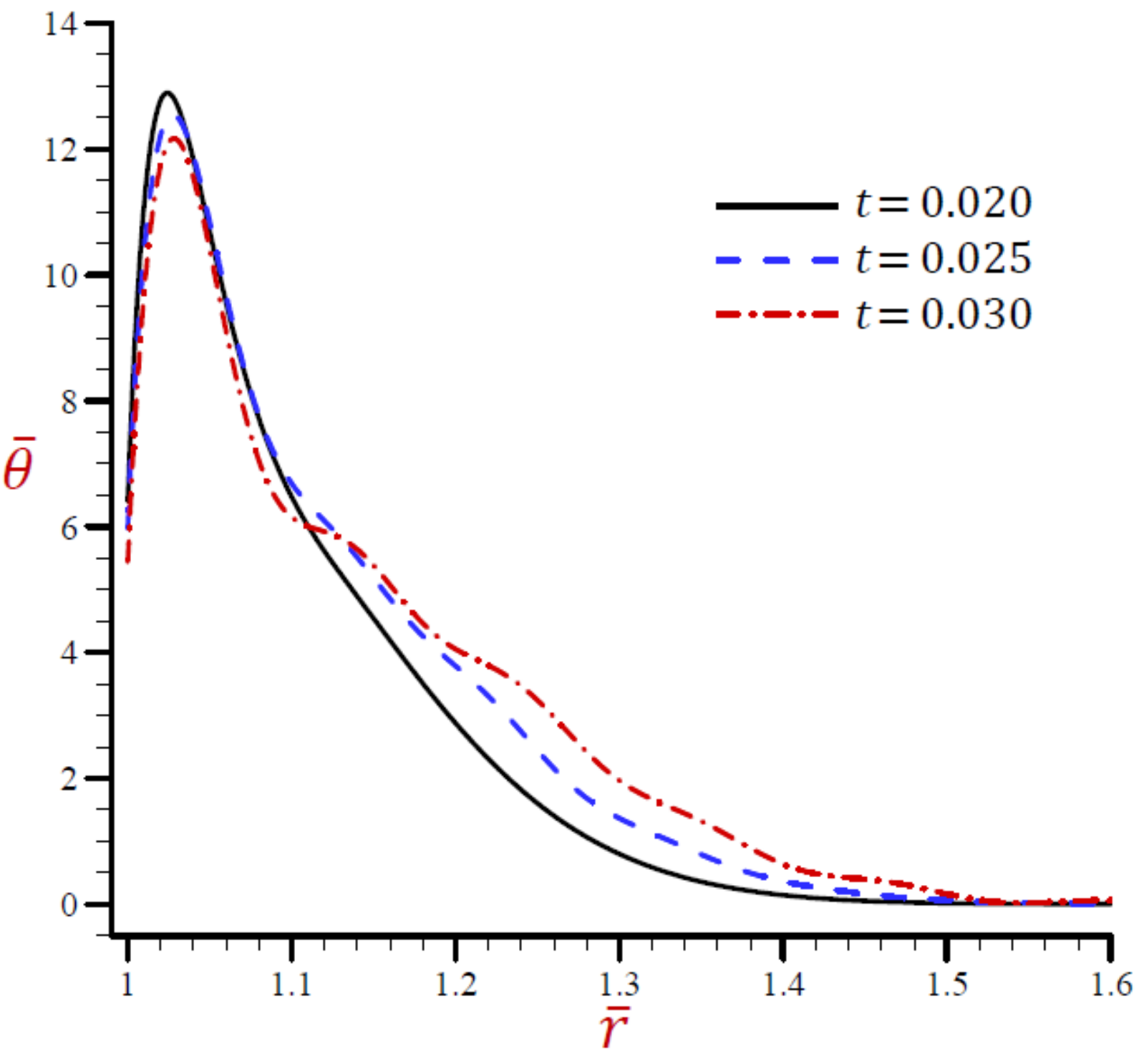
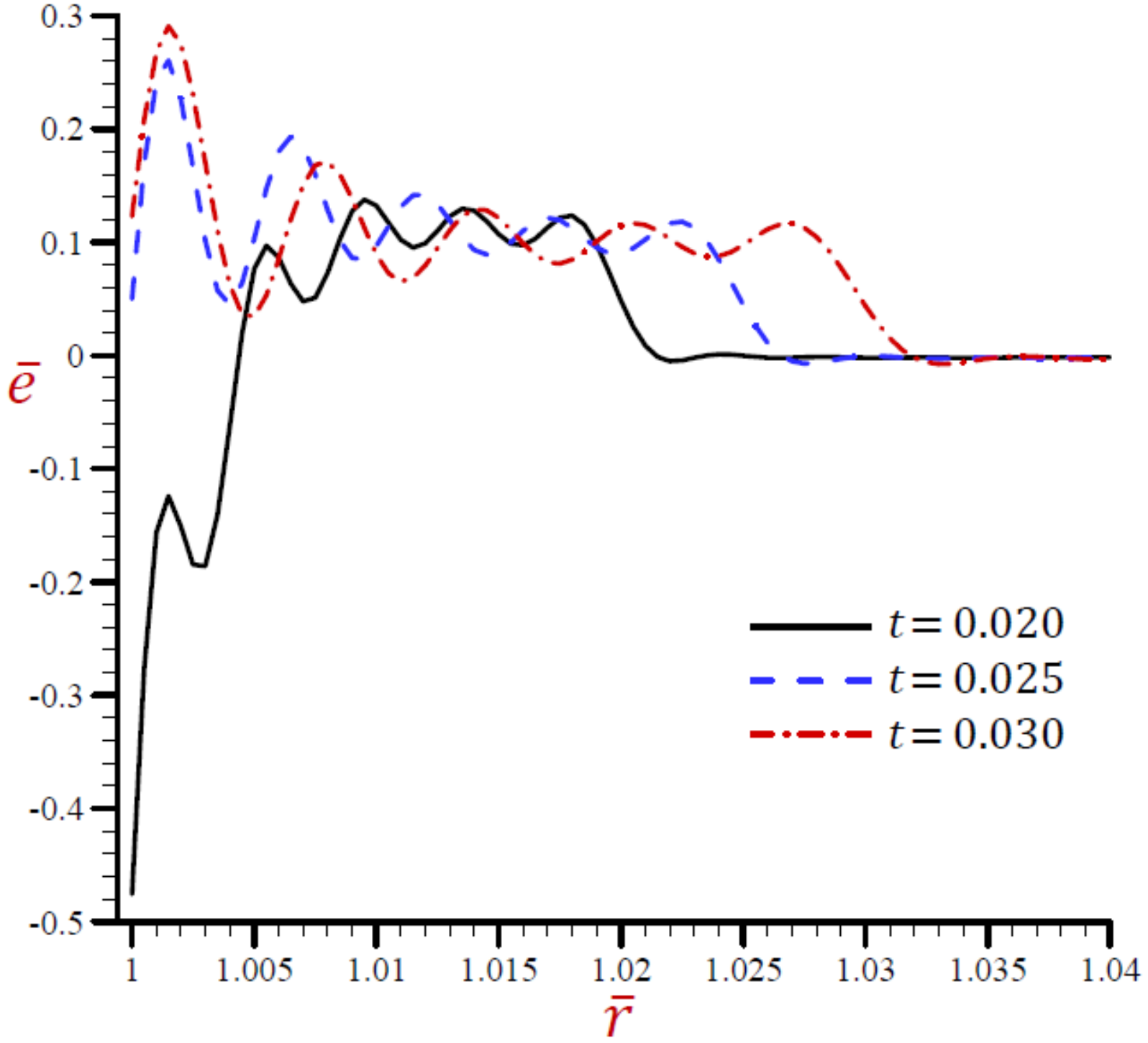
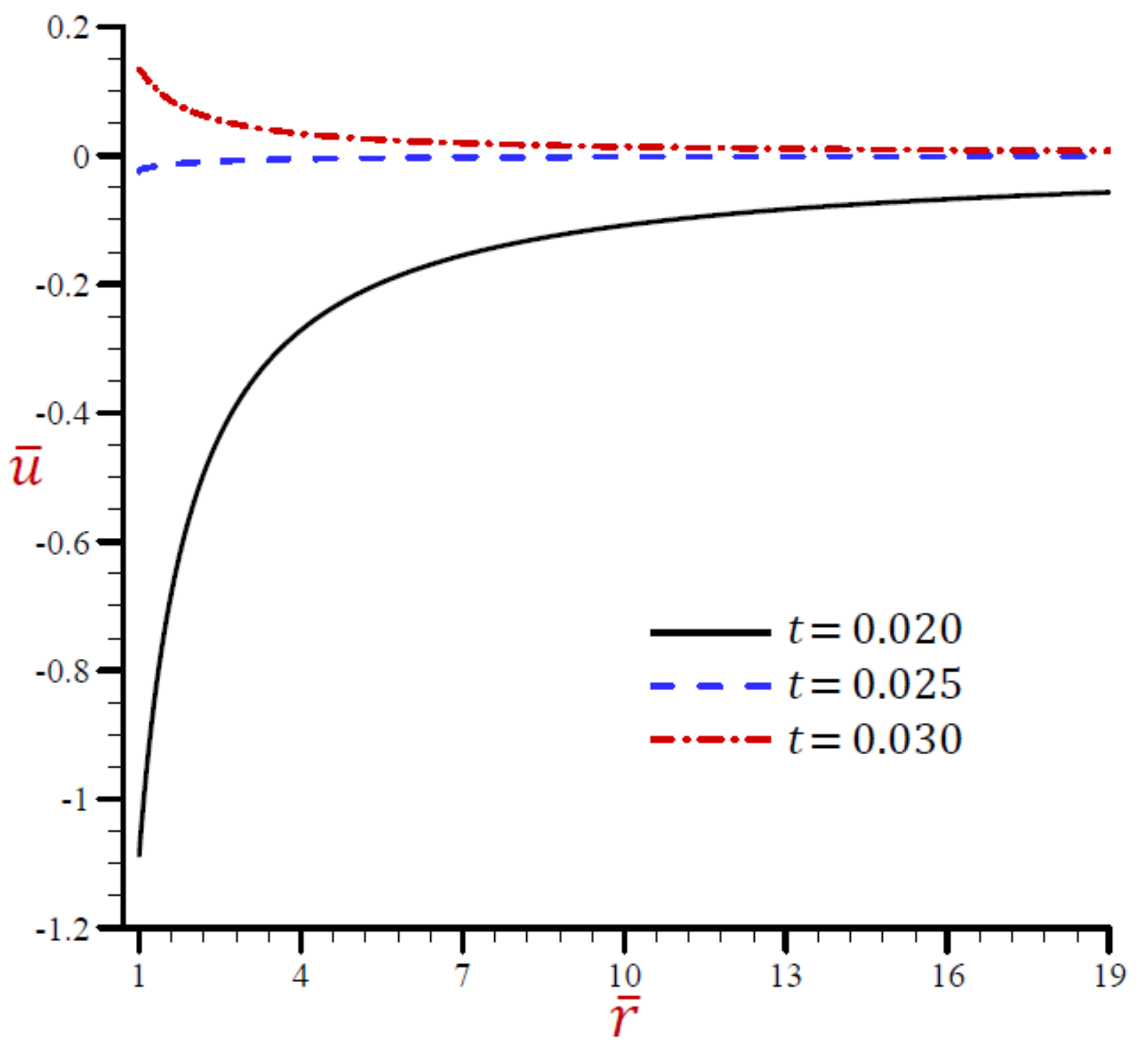
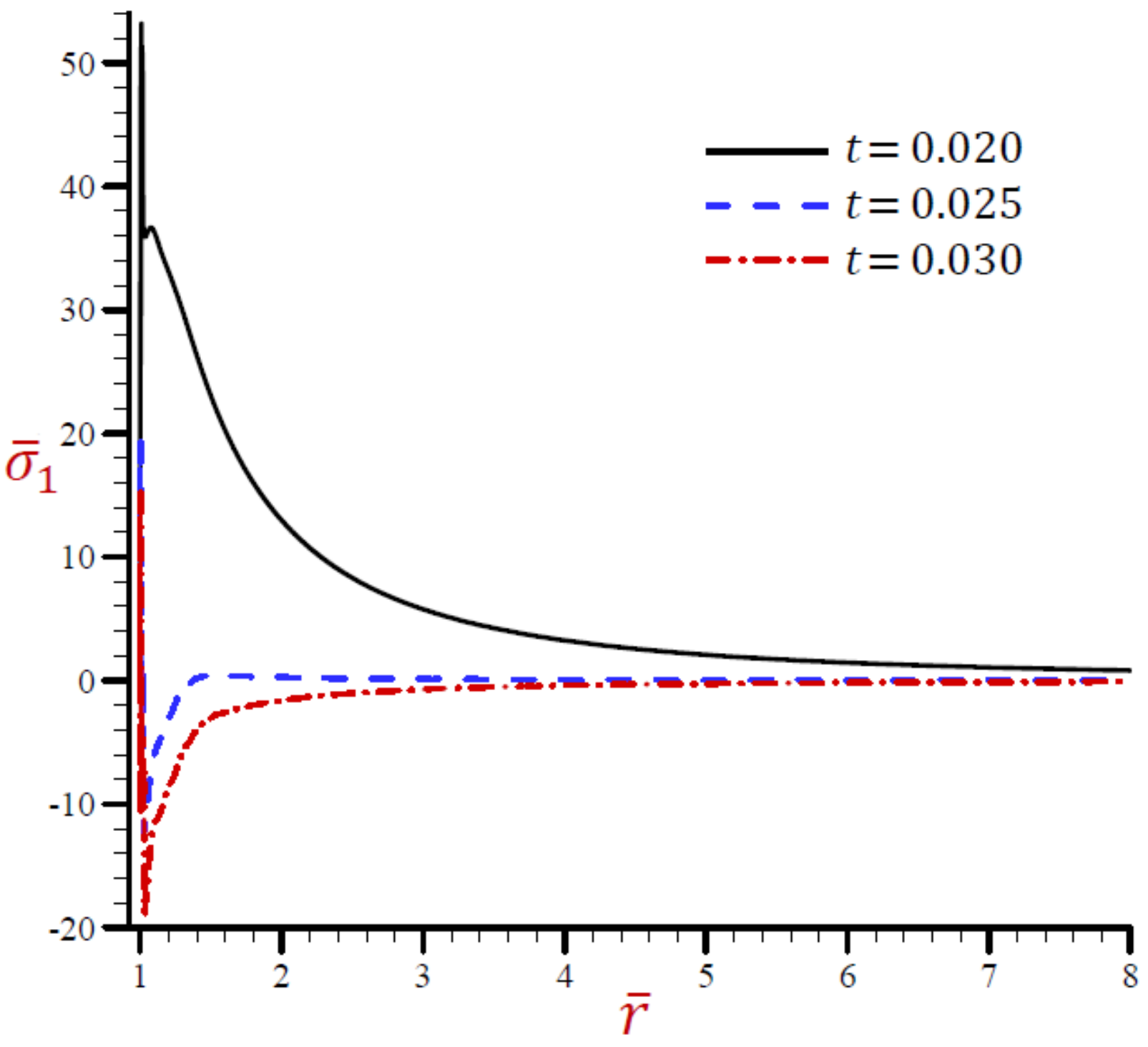
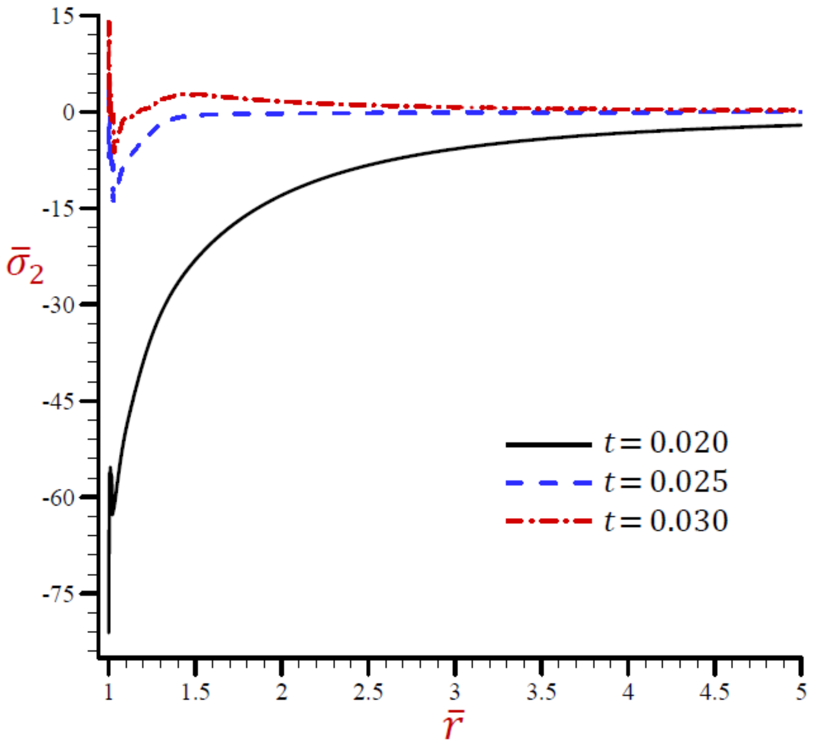
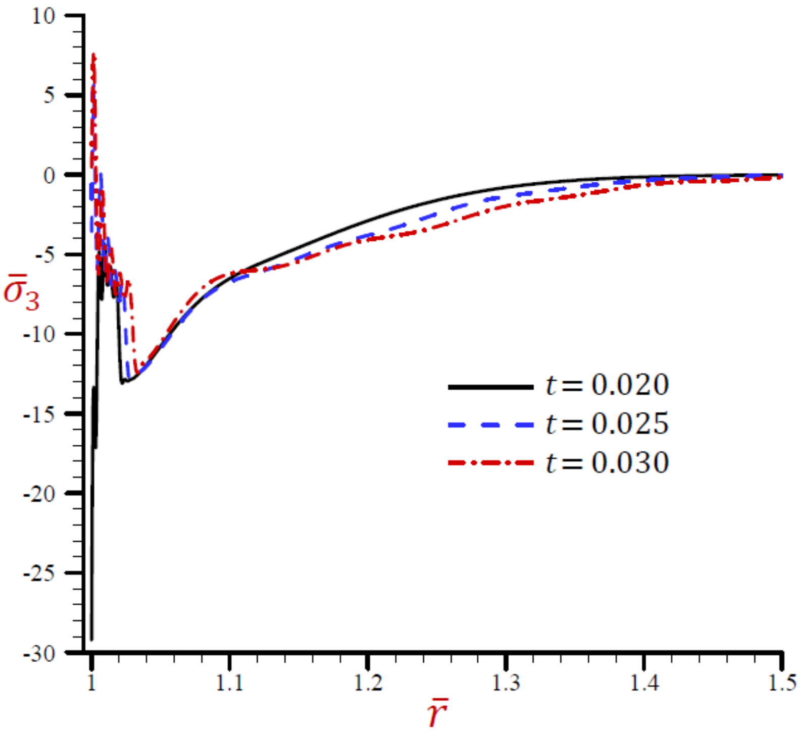
5.3.3. Effect of Dimensionless Time

The effects of dimensionless time t on all field variables based upon the RDPL theory are presented in Figure 19, Figure 20, Figure 21, Figure 22, Figure 23 and Figure 24. Figure 19 shows the effect of t on the temperature θ ¯ across the radial direction of the cylindrical cavity. Similar graphs of the rest of field quantities are presented in Figure 20, Figure 21, Figure 22, Figure 23 and Figure 24. It is clear in Figure 19 that the temperature θ ¯ vibrates across the radial direction for different values of t . The temperature θ ¯ is no longer increasing and has its maximum values at r = 1.04 . The temperature vanishes as r increases and this is irrespective of the value of the dimensionless time. Figure 20 shows that the dilatation e ¯ vibrates across the radial direction of the cylindrical cavity nicely. The wave magnitude increases as t increases. In Figure 21, the radial displacement u ¯ is rapidly increasing along the radial directional of the cylindrical cavity when t = 0.02 while u ¯ is slowly increasing when t = 0.02 5. In addition,   u ¯ is slowly decreasing when t = 0.03 It is clear that at a fixed position u ¯ increases as t increases.
The radial stress σ ¯ 1 across the radial direction of the cylindrical utilizing the RDPL theory is plotted in Figure 22 for different values of t . The radial stress σ ¯ 1 vibrates in a very small range, then it increases for t = 0.025 and 0.03 while it decreases when t = 0.02 . At any fixed position, the radial stress σ ¯ 1 increases as t decreases. The hoop stress σ ¯ 2 is plotted across the radial direction of the cylindrical using the RDPL theory in Figure 23 for distinct values of t . It vibrates in a very small range, then it increases for t = 0.02 while it decreases when t = 0.025 and 0.03 . At any fixed position, the hoop stress σ ¯ 2 increases as t increases.
Finally, the axial stress σ ¯ 3 is plotted across the radial direction of the cylindrical using the RDPL theory in Figure 24 for distinct values of t . It rabidly vibrates in a very small range 1 r < 1.035 , then it slowly vibrates and increases to vanish at large values of r .

6. Conclusions

The refined dual-phase-lag theory is presented to get novel and accurate outcomes of the variable quantities such as temperature, dilatation, displacement, and stresses. The multi-time derivatives heat equation is illustrated in the present formulation. The constitutive equations for the stresses in cylindrical coordinates are added to discuss the thermoelastic coupling response of an unbounded body with a cylindrical hole due to a traveling heat source. From the unified model, one can construct other theories concerning coupled dynamical thermoelasticity (CTE theory), Lord and Shulman generalized thermoelasticity theory (L–S theory), Green and Naghdi generalized thermoelasticity theory (G–N theory) without energy dissipation as well as a simple generalized thermoelasticity theory with dual-phase-lag (SDPL theory). The system of two highly-time-derivatives differential coupled equations is solved, and all field variables are gained for the thermoelastic coupling response of an unbounded medium with a cylindrical cavity. Different validation examples and applications are presented to compare all theories with the refined one. A sample set of plots are illustrated along the radial direction of the cylindrical cavity. Two tables are reported for a validation example to serve as benchmark results for future comparisons with other investigators. The reported and illustrated results show various behaviors of all field quantities and the effects of the velocity of heat source, angular frequency of thermal vibration, and dimensionless time parameters. The G–N theory gives suitable results in a small range. However, the RDPL theory yields modified and accurate results.

Author Contributions

Conceptualization, A.M.Z., D.S.M., and A.M.A.; data collection, A.M.A.; methodology, A.M.Z. and A.M.A.; software, A.M.Z. and A.M.A.; validation, A.M.Z. and D.S.M.; writing—original draft preparation, A.M.A. and D.S.M.; writing—review and editing, A.M.Z. All authors have read and agreed to the published version of the manuscript.

Funding

This research was funded by the Deanship of Scientific Research (DSR) at King Abdulaziz University, Jeddah, under grant no. (DG: 18-130-1441).

Institutional Review Board Statement

Not applicable.

Informed Consent Statement

Not applicable.

Data Availability Statement

Not applicable.

Acknowledgments

This project was funded by the Deanship of Scientific Research (DSR) at King Abdulaziz University, Jeddah, under grant no. (DG: 18-130-1441). The authors, therefore, acknowledge with thanks DSR for technical and financial support.

Conflicts of Interest

The authors declare no conflict of interest.

Nomenclature

α t thermal expansion coefficient K 1
C e specific heat at uniform strain J   kg 1   K 1
δ i j Kronecker delta function
e φ φ hoop strain
e r r radial strain
e dilatation
e i j linear strain tensor
ϑ the velocity of heat source m   s 1
γ 3 λ + 2 μ α t thermal modulus N   m 2   K 1
H t Heaviside unit step function
k coefficient of heat conductivity W   m 1   K 1
k * rate of thermal conductivity of an isotropic material W   m 1   K 1
λ , μ Lame’s constants N   m 2
ρ material density kg   m 3
R The radius of the cylindrical cavity m
r , φ , z cylindrical coordinates system
σ i j stress tensor components N   m 2
σ φ z , σ z r , σ r φ shear stresses N   m 2
σ φ φ hoop stress N   m 2
σ r r radial stress N   m 2
σ z z axial stress N   m 2
s Laplace parameter
θ = T T 0 temperature change K
θ 0 thermal constant K
T 0 environment temperature K
τ q phase-lag of heat flux s
τ θ phase-lag of temperature gradient s
τ 0 first relaxation time s
ω angular frequency of thermal vibration rad   s 1
Q 0 strength of heat source W   m 3
δ delta function
q heat flux vector W   m 2
u r radial displacement m
u ϕ hoop displacement m
u z axial displacement m

References

  1. Duhamel, J.M.C. Second memoire sur les phenomes thermomechaniques. J. École Polytech. 1837, 15, 1–57. [Google Scholar]
  2. Biot, M.A. Thermoelasticity and irreversible thermodynamics. J. Appl. Phys. 1956, 27, 240–253. [Google Scholar] [CrossRef]
  3. Lord, H.W.; Shulman, Y. A generalized dynamical theory of thermoelasticity. J. Mech. Phys. Solids 1967, 15, 299–309. [Google Scholar] [CrossRef]
  4. Green, A.E.; Lindsay, K.A. Thermoelasticity. J. Elast. 1972, 2, 1–7. [Google Scholar] [CrossRef]
  5. Chandrasekharaiah, D.S. Hyperbolic thermoelasticity: A review of recent literature. Appl. Mech. Rev. 1998, 51, 705–729. [Google Scholar] [CrossRef]
  6. Green, A.E.; Naghdi, P.M. A re-examination of the basic postulates of thermomechanics. Proc. R. Soc. A 1991, 432, 171–194. [Google Scholar]
  7. Green, A.E.; Naghdi, P.M. On undamped heat waves in an elastic solid. J. Therm. Stresses 1992, 15, 253–264. [Google Scholar] [CrossRef]
  8. Green, A.E.; Naghdi, P.M. Thermoelasticity without energy dissipation. J. Elast. 1993, 31, 189–208. [Google Scholar] [CrossRef]
  9. Tzou, D.Y. A unified approach for heat conduction from macro- to micro-scales. J. Heat Transf. 1995, 117, 8–16. [Google Scholar] [CrossRef]
  10. Tzou, D.Y. Macro- to Microscale Heat Transfer: The Lagging Behavior; Taylor & Francis: Washington, DC, USA, 1997. [Google Scholar]
  11. Zenkour, A.M. Thermo-diffusion of solid cylinders based upon refined dual-phase-lag models. Multid. Model. Mater. Struct. 2020, 16, 1417–1434. [Google Scholar] [CrossRef]
  12. Zenkour, A.M. Wave propagation of a gravitated piezo-thermoelastic half-space via a refined multi-phase-lags theory. Mech. Adv. Mater. Struct. 2020, 27, 1923–1934. [Google Scholar] [CrossRef]
  13. Zenkour, A.M. Thermoelastic diffusion problem for a half-space due to a refined dual-phase-lag Green-Naghdi model. J. Ocean Eng. Sci. 2020, 5, 214–222. [Google Scholar] [CrossRef]
  14. Zenkour, A.M. Thermal-shock problem for a hollow cylinder via a multi-dual-phase-lag theory. J. Therm. Stresses 2020, 43, 687–706. [Google Scholar] [CrossRef]
  15. Zenkour, A.M. Exact coupled solution for photothermal semiconducting beams using a refined multi-phase-lag theory. Opt. Laser Tech. 2020, 128, 106233. [Google Scholar] [CrossRef]
  16. Chandrasekharaiah, D.S.; Srinath, K.S. Axisymmetric thermoelastic interactions without energy dissipation in an unbounded body with cylindrical cavity. J Elast. 1997, 46, 19–31. [Google Scholar] [CrossRef] [Green Version]
  17. Allam, M.N.; Elsibai, K.A.; Abouelregal, A.E. Thermal stresses in a harmonic field for an infinite body with a circular cylindrical hole without energy dissipation. J. Therm. Stresses 2002, 25, 57–67. [Google Scholar] [CrossRef]
  18. Ezzat, M.A.; El-Bary, A.A. Fractional order theory to an infinite thermo-viscoelastic body with a cylindrical cavity in the presence of an axial uniform magnetic field. J. Electromag. Waves Appl. 2017, 31, 495–513. [Google Scholar] [CrossRef]
  19. Ezzat, M.A.; El-Bary, A.A. Application of fractional order theory of magneto-thermoelasticity to an infinite perfect conducting body with a cylindrical cavity. Microsyst. Technol. 2017, 23, 2447–2458. [Google Scholar] [CrossRef]
  20. Sharma, J.N.; Sharma, N.K.; Sharma, K.K. Diffusion in generalized thermoelastic solid in an infinite body with cylindrical cavity. Proc. Natl. Acad. Sci. India Sect. A Phys. Sci. 2013, 83, 353–364. [Google Scholar] [CrossRef]
  21. Kumar, R.; Mukhopadhyay, S. Effects of three phase lags on generalized thermoelasticity for an infinite medium with a cylindrical cavity. J. Therm. Stresses 2009, 32, 1149–1165. [Google Scholar] [CrossRef]
  22. Mukhopadhyay, S.; Kumar, R. Thermoelastic interactions on two-temperature generalized thermoelasticity in an infinite medium with a cylindrical cavity. J. Therm. Stresses 2009, 32, 341–360. [Google Scholar] [CrossRef]
  23. Kumar, R.; Prasad, R.; Kumar, R. Thermoelastic interactions on hyperbolic two-temperature generalized thermoelasticity in an infinite medium with a cylindrical cavity. Eur. J. Mech. A Solids 2020, 82, 233–245. [Google Scholar] [CrossRef]
  24. Sarkar, N.; Mondal, S. Transient responses in a two-temperature thermoelastic infinite medium having cylindrical cavity due to moving heat source with memory-dependent derivative. ZAMM J. 2019, 99, 1–19. [Google Scholar] [CrossRef]
  25. Sharma, J.N.; Kumari, N.; Sharma, K.K. Diffusion in a generalized thermoelastic solid in an infinite body with a cylindrical cavity. J. Appl. Mech. Tech. Phys. 2013, 54, 819–831. [Google Scholar] [CrossRef]
  26. Mukhopadhyay, S.; Kumar, R. A problem on thermoelastic interactions in an infinite medium with a cylindrical hole in generalized thermoelasticity III. J. Comput. Appl. Mech. 2008, 31, 455–475. [Google Scholar] [CrossRef]
  27. Xia, R.-H.; Tian, X.-G.; Shen, Y.-P. The influence of diffusion on generalized thermoelastic problems of infinite body with a cylindrical cavity. Int. J. Eng. Sci. 2009, 47, 669–679. [Google Scholar] [CrossRef]
  28. Xiong, Q.-L.; Tian, X.-G. Thermoelastic study of an infinite functionally graded body with a cylindrical cavity using the Green-Naghdi model. J. Therm. Stresses 2012, 35, 718–732. [Google Scholar] [CrossRef]
  29. Abouelregal, A.E. Generalized thermoelastic infinite transversely isotropic body with a cylindrical cavity due to moving heat source and harmonically varying heat. Meccanica 2013, 48, 1731–1745. [Google Scholar] [CrossRef]
  30. Youssef, H.M. Two-temperature generalized thermoelastic infinite medium with cylindrical cavity subjected to moving heat source. Arch. Appl. Mech. 2010, 80, 1213–1224. [Google Scholar] [CrossRef]
  31. Youssef, H.M. State-space approach to two-temperature generalized thermoelasticity without energy dissipation of medium subjected to moving heat source. Appl. Math. Mech. 2013, 34, 63–74. [Google Scholar] [CrossRef]
  32. Shaw, S.; Mukhopadhyay, B. Moving heat source response in a thermoelastic microelongated solid. J. Eng. Phys. Thermophys. 2013, 86, 716–722. [Google Scholar] [CrossRef]
  33. Sarkar, N.; Lahiri, A. Interactions due to moving heat sources in generalized thermoelastic half-space using L-S model. Int. J. Appl. Mech. Eng. 2013, 18, 815–831. [Google Scholar] [CrossRef] [Green Version]
  34. Youssef, H.M. State-space approach to fractional order two-temperature generalized thermoelastic medium subjected to moving heat source. Mech. Adv. Mater. Struct. 2013, 20, 47–60. [Google Scholar] [CrossRef]
  35. Xia, R.-H.; Tian, X.-G.; Shen, Y.-P. Dynamic response of two-dimensional generalized thermoelastic coupling problem subjected to a moving heat source. Acta Mech. Solida Sin. 2014, 27, 300–305. [Google Scholar] [CrossRef]
  36. Abbas, I.A. A GN model for thermoelastic interaction in a microscale beam subjected to a moving heat source. J. Comput. Acta Mech. 2015, 226, 2527–2536. [Google Scholar] [CrossRef]
  37. Youssef, H.M. Generalized thermoelastic infinite medium with cylindrical cavity subjected to moving heat source. Mech. Res. Commun. 2009, 36, 487–496. [Google Scholar] [CrossRef]
  38. Zenkour, A.M. Thermal diffusion of an unbounded solid with a spherical cavity via refined three-phase-lag Green–Naghdi models. Indian J. Phys. 2021; in press. [Google Scholar] [CrossRef]
  39. Kutbi, M.A.; Zenkour, A.M. Refined dual-phase-lag Green–Naghdi models for thermoelastic diffusion in an infinite medium. Waves Rand. Complex Media, 2021; in press. [Google Scholar] [CrossRef]
  40. Zenkour, A.M.; El-Mekawy, H.F. On a multi-phase-lag model of coupled thermoelasticity. Int. Commun. Heat Mass Transf. 2020, 116, 104722. [Google Scholar] [CrossRef]
  41. Sobhy, M.; Zenkour, A.M. Modified three-phase-lag Green–Naghdi models for thermomechanical waves in an axisymmetric annular disk. J. Therm. Stresses 2020, 43, 1017–1029. [Google Scholar] [CrossRef]
Figure 1. The temperature θ ¯ across the radial direction of the cylindrical cavity conferring to all theories.
Mathematics 10 00009 g001
Figure 2. The dilatation e ¯ across the radial direction of the cylindrical cavity conferring to all theories.
Mathematics 10 00009 g002
Figure 3. The radial displacement u ¯ across the radial direction of the cylindrical cavity conferring to all theories.
Mathematics 10 00009 g003
Figure 4. The radial stress σ ¯ 1 across the radial direction of the cylindrical cavity conferring to all theories.
Mathematics 10 00009 g004
Figure 5. The hoop stress σ ¯ 2 across the radial direction of the cylindrical cavity conferring to all theories.
Mathematics 10 00009 g005
Figure 6. The axial stress σ ¯ 3 across the radial direction of the cylindrical cavity conferring to all theories.
Mathematics 10 00009 g006
Figure 7. Effect of ω on temperature θ ¯ across the radial direction of the cylindrical cavity utilizing the RDPL model.
Mathematics 10 00009 g007
Figure 8. Effect of ω on dilatation e ¯ across the radial direction of the cylindrical cavity utilizing the RDPL model.
Mathematics 10 00009 g008
Figure 9. Effect of ω on radial displacement u ¯ across the radial direction of the cylindrical cavity utilizing the RDPL model.
Mathematics 10 00009 g009
Figure 10. Effect of ω on radial stress σ ¯ 1 across the radial direction of the cylindrical cavity utilizing the RDPL model.
Mathematics 10 00009 g010
Figure 11. Effect of ω on radial stress σ ¯ 2 across the radial direction of the cylindrical cavity utilizing the RDPL model.
Mathematics 10 00009 g011
Figure 12. Effect of ω on radial stress σ ¯ 3 across the radial direction of the cylindrical cavity utilizing the RDPL model.
Mathematics 10 00009 g012
Figure 13. Effect of ϑ on temperature θ ¯ across the radial direction of the cylindrical cavity utilizing the RDPL model.
Mathematics 10 00009 g013
Figure 14. Effect of ϑ on dilatation e ¯ across the radial direction of the cylindrical cavity utilizing the RDPL model.
Mathematics 10 00009 g014
Figure 15. Effect of ϑ on radial displacement u ¯ across the radial direction of the cylindrical cavity utilizing the RDPL model.
Mathematics 10 00009 g015
Figure 16. Effect of ϑ on radial stress σ ¯ 1 across the radial direction of the cylindrical cavity utilizing the RDPL model.
Mathematics 10 00009 g016
Figure 17. Effect of ϑ on radial stress σ ¯ 2 across the radial direction of the cylindrical cavity utilizing the RDPL model.
Mathematics 10 00009 g017
Figure 18. Effect of ϑ on radial stress σ ¯ 3 across the radial direction of the cylindrical cavity utilizing the RDPL model.
Mathematics 10 00009 g018
Figure 19. Effect of t on temperature θ ¯ across the radial direction of the cylindrical cavity utilizing the RDPL model.
Mathematics 10 00009 g019
Figure 20. Effect of t on dilatation e ¯ across the radial direction of the cylindrical cavity utilizing the RDPL model.
Mathematics 10 00009 g020
Figure 21. Effect of t on radial displacement u ¯ across the radial direction of the cylindrical cavity utilizing the RDPL model.
Mathematics 10 00009 g021
Figure 22. Effect of t on radial stress σ ¯ 1 across the radial direction of the cylindrical cavity utilizing the RDPL model.
Mathematics 10 00009 g022
Figure 23. Effect of t on radial stress σ ¯ 2 across the radial direction of the cylindrical cavity utilizing the RDPL model.
Mathematics 10 00009 g023
Figure 24. This is a figure. Schemes follow the same formatting Effect of t on radial stress σ ¯ 3 across the radial direction of the cylindrical cavity utilizing the RDPL model.
Mathematics 10 00009 g024
Table 1. Effect of the velocity of heat source ϑ on the field variables of different thermoelasticity theories with t = 0.03 , r = 1.2 , ω = 0 .
ϑ VariableCTEG–NL–SSDPLRDPL
N = 1 N = 3 N = 4 N = 5
17 θ ¯ 3.52067980.00742774.55586513.46426843.64606483.90838854.2446350
e * −6.4643864−0.7652114−10.4814114−6.5686154−6.8240864−7.0147188−7.2539067
u * −50.65710910.05404790.0234225−37.4998105−4.51462615.714174511.3103719
σ ¯ 1 16.5744843−0.0362606−4.665540711.3944541−1.9149801−6.2492888−8.8146180
σ ¯ 2 −23.70876430.0104058−4.5968524−18.4174099−5.4752409−1.66831980.2210782
σ ¯ 3 −3.5517066−0.0111005−4.6061725−3.4957955−3.6788182−3.9420569−4.2794514
20 θ ¯ 4.1072506−0.00296144.43065144.08002384.32065294.60903194.9665501
e * −6.51052780.3051538−10.1923716−6.6189071−6.8807134−7.0727326−7.3110451
u * −0.23065390.03823360.02312362.42865362.58908971.91947001.3751839
σ ¯ 1 −4.0778064−0.0093305−4.5374406−5.1097870−5.4167623−5.4405303−5.5837524
σ ¯ 2 −4.23027890.0196396−4.4703704−3.1454027−3.3234490−3.8791992−4.4544390
σ ¯ 3 −4.13849900.0044260−4.4795715−4.1117924−4.3536781−4.6429788−5.0016408
e * = 10 4 e ¯ , u * = 10 2 u ¯ .
Table 2. Effect of the velocity of heat source ϑ on the field variables of different thermoelasticity theories with t = 0.03 , r = 1.2 , ω = 20 .
ϑ VariableCTEG–NL–SSDPLRDPL
N = 1 N = 3 N = 4 N = 5
17 θ ¯ 3.28353980.00742774.55281823.24474473.45089273.71882994.0555735
e * −6.2860288−0.7652114−10.4740672−6.3932523−6.6542973−6.8464693−7.0855337
u * −50.65725090.05404790.0234210−37.4999432−4.51474345.714062811.3102642
σ ¯ 1 16.8133885−0.0362606−4.662422911.6157097−1.7181357−6.0580749−8.6239015
σ ¯ 2 −23.47082470.0104058−4.5937709−18.1970973−5.2793005−1.47799820.4109050
σ ¯ 3 −3.3137105−0.0111005−4.6030904−3.2754301−3.4828312−3.7516908−4.0895818
20 θ ¯ 3.8701106−0.00296144.42760453.86050014.12548084.41947344.7774886
e * −6.33217020.3051538−10.1850275−6.4435440−6.7109243−6.9044831−7.1426721
u * −0.23079570.03823360.02312212.42852092.58897241.91935831.3750762
σ ¯ 1 −3.8389023−0.0093305−4.5343228−4.8885315−5.2199179−5.2493164−5.3930359
σ ¯ 2 −3.99233930.0196396−4.4672888−2.9250901−3.1275086−3.6888775−4.2646122
σ ¯ 3 −3.90050300.0044260−4.4764894−3.8914270−4.1576911−4.4526127−4.8117711
e * = 10 4 e ¯ , u * = 10 2 u ¯ .
Publisher’s Note: MDPI stays neutral with regard to jurisdictional claims in published maps and institutional affiliations.

