1. Introduction
Modelling and simulation continues to play an increasingly larger role within high precision manufacturing. The possibility of using a virtual environment to validate a design or a manufacturing process in advance is becoming more and more important within many industries. Potential problems can be foreseen and mitigated, and changes can be made to the process in order to achieve more precision and reliability in the final product.
The aerospace industry is rapidly increasing its focus on these technologies. Requirements on quality and reliability are extremely high, and the designs are becoming increasingly complex in order to meet rising demands on low weight and fuel burn. New manufacturing methods will be necessary in order to push the limits of high precision manufacturing processes and get ready for the next generation of aircraft engines.
Geometry assurance is a widely used methodology aimed at managing the effects of tolerances and variation on a manufacturing process [
1]. This is done through various computational tools which are used to predict the outcome of a process under different conditions. A statistical approach is often applied in order to analyze the production process. Depending on how the fixture is designed and what the tolerances are, the process will be sensitive to certain types of variation and robust towards others. Virtual tools have been proposed for simulating variation in assemblies [
2]. The goal is to design the process in a way which is as robust as possible with regards to the expected geometrical variation of the parts and tools involved in production.
Within the aerospace industry, there is a growing effort to produce parts through fabrication [
3]. In this context, fabrication refers to production processes where several smaller parts are joined together through welding to create the final product. This has several advantages over the traditional method of starting with a single large casting or forging and then removing excess material, but it also introduces more variation to the process. In a fabricated assembly, the geometrical variation of every single part must be taken into account. In order to ensure a sufficiently good fit in the interfaces between the parts, many different factors have to be considered in order to calibrate the process.
This calibration procedure usually involves heavy use of the geometry assurance toolbox. However, as the requirements continue to increase, the challenge of keeping a fabrication process within tolerance becomes more difficult. At some point, it is no longer feasible to approach each individual assembly of parts with identical settings and process parameters. Small differences at the part level makes every assembly unique and in order to reliably achieve a good outcome, each assembly will require small adjustments. This is commonly referred to as mass customization, meaning that each product is approached individually rather than interchangeably.
When it comes to fabrication, selective assembly has been proposed as a way of individualizing the process by finding the optimal way of combining available parts [
4]. However, this approach is more efficient for high volume processes with a large amount of available parts. For the aerospace industry, production volumes are usually low. This requires an approach focusing on adaptive production. Geometry assurance activities must be applied to each assembly individually. This type of approach has been suggested in [
5,
6], proposing a digital twin for advanced production processes in the aerospace industry.
The vision of a digital twin was first proposed by NASA for aeronautical applications [
7], where a virtual system would mirror its physical counterpart by applying measurement data to a simulated model. This enables the digital twin to accurately predict the failure of a simulated aircraft component based on the loads that it has been subjected to, rather than relying on failure predictions based on generic or worst-case use scenarios. The digital twin concept presents an opportunity to improve upon an early prediction of a system property by essentially replacing statistical predictions with real data as it becomes available during use. This concept can be extended far beyond the use case of aircraft component lifecycle management. Digital twins have been suggested for a broad range of mechanical systems [
8], and the possibility of creating virtual models and setting up digital twins is becoming increasingly important within production engineering [
9]. A digital twin can be categorized in different ways [
10], but it always relies on some sort of measurement data from the system being mirrored [
11]. Virtual tools can then be applied in order to improve the process [
12]. Welding within advanced manufacturing poses a difficult challenge when it comes to variation, and has been suggested as a suitable area of application for a digital twin [
13].
Scope of Paper
This paper proposes a digital twin approach consisting of an analysis loop that involves data collection, virtual assembly, non-nominal welding simulation, and variation analysis. The method is focused on increased geometrical quality in fabrication of aerospace engine components. A case study is conducted where a sheet metal part and a machined part are joined through welding. A digital twin based on non-nominal welding simulation is used to predict the outcome of the welding process, and the performance of the digital twin is evaluated by comparing it to the real welding outcome. Three different welding simulation methods are applied, including a conventional transient simulation and a novel simulation approach called SCV (Steady-state Convex hull Volumetric shrinkage). The results are analyzed in order to make conclusions on the feasibility of the presented approach in an industrial context.
2. Welding Simulation
Welding is used in many types of manufacturing processes for joining parts into larger assemblies. As previously mentioned, welding is an important part of fabrication processes. During welding of an assembly, a heat source moves along the interface between two parts. This causes the metal to melt close to the weld seam, joining the two parts at the interface as the metal cools and solidifies. Welding causes a large temporary heat concentration in the material, with high temperature gradients close to the heat source. This leads to internal stresses in the material and distortion of the geometry of the assembly. When welding is used on an assembly with high requirements and tight tolerances, these effects must be taken into account during manufacturing. This is done by setting up a simulation of the welding process to predict how it will affect the assembly.
The goal of a welding simulation is to calculate the distortion and residual stresses that remain after the welding procedure, in order to avoid problems with quality and tolerances. Welding affects the heat distribution, the structural mechanics, and the micro structure of the material. In this case, the focus is mainly on the deformation of the part and it has been shown that changes to the micro structure can then be ignored [
14]. The changes to the structural mechanics are driven by the transient temperature field, which needs to be modelled in the simulation. The temperature in each time step is calculated separately, followed by a structural analysis to calculate how the material deforms in response to the temperature changes.
In order to model the heat flux from the weld gun, a double ellipsoid is commonly used [
15]. It consists of two ellipsoids, placed in front and behind of the heat source. The double ellipsoid has been designed in order to give an accurate structural response, and can be fitted according to experimental outcomes. In a full transient welding simulation, the heat distribution in the material is first calculated at each time step by modelling the heat source. This is followed by a simulation that calculates the mechanical response at each time step based on the heat distribution. The result is a prediction of the deformation and stresses that will result from the welding procedure. This can be useful in early product development phases, where different design concepts can be evaluated based on the predicted weld quality.
3. Non-Nominal Welding Simulation for Advanced Manufacturing
Welding simulation with nominal geometries is a well-proven and established method. Within advanced manufacturing, it is normally used during the design phase to predict how the added heat is going to affect the assembly. In this phase before manufacturing has started, there are no significant time constraints. The simulations are performed with high mesh resolution and small time step increments to achieve the best possible accuracy, meaning that simulations can take several days to complete. A single nominal mesh is used in the simulation.
The simulations performed during the design phase assume that all parts in the welded assembly are completely nominal and free from geometrical variation. In reality, all parts have some amount of geometrical variation when they enter the assembly process. This can cause a mismatch between the weld interfaces, which may affect the properties of the weld seam [
4]. If the mismatch is too large, the parts may require clamping to be applied in the weld fixture, which causes stresses in the material.
It has been shown that the deformation caused by welding is coupled to the geometrical variation in the parts [
16]. Small changes to the geometry of the parts will affect the final result of the welding procedure [
17,
18]. In [
16], all non-nominal welding simulations are fully transient. In a context were many different part geometries and assemblies need to be simulated within a limited amount of time, transient simulations are prohibitively slow since they are not designed to work within time constraints. Welding simulation with geometrical variation requires multiple meshes to be analyzed, one for each physical part. Faster welding simulation methods are required in order to enable non-nominal welding simulation.
Several different approaches have been suggested for faster welding simulation. Inherent Strain uses elasto-plastic analysis on a segment of the weld to obtain the equivalent elastic strain, which can then be applied along the entire weld [
19]. Another type of approach suggests a simplified analytical model to predict the distortion caused by welding [
20]. It has also been proposed that the distortion can be predicted by relating it directly to the contraction of the melted material as it cools and solidifies. This is called Volumetric Shrinkage and has been shown to yield good experimental results [
21,
22].
Due to its compatibility with geometric variation in the weld interface, volumetric shrinkage has been implemented in the SCV method, a welding simulation method aimed specifically at fast simulation including geometrical variation in parts [
23]. The method consists of three main steps: a steady state computation of the thermal distribution in the part, computation of a 2D melted zone, and finally, application of thermal loads on a 3D model (see
Figure 1). This is much faster than a full transient simulation since the mechanical response does not have to be calculated at each time step. The robustness of the SCV method has been investigated in [
24], and the possibility of dividing the weld seam into multiple segments with different melt zones was shown in [
25]. By segmenting the weld seam and using separate melt zones for each segment, it is possible to adapt the SCV method to weld seams with increased complexity such as curvatures. It has been shown that the SCV method works well in combination with geometrical variation, making it suitable for simulating welds on non-nominal assemblies. However, previous tests with the SCV method has only compared it to traditional high resolution welding simulations rather than experimental welding results, and the geometrical variation has been generated statistically rather than measured from physical parts.
The use of 3D scanning for in-line measurements is on its way to becoming common practice within advanced manufacturing, marking an important shift as geometrical data from individual parts is made available at multiple stages of the manufacturing process. The technology works by capturing light that is reflected of the surface of the measured part. By sweeping a scanner over the entire part, the surface can be converted into a point cloud where each coordinate corresponds to a point on the part [
26]. A 3D scanner can quickly capture a set of data that describes the entire geometry of a part, rather than focusing on specific measurement points. Since the measurements rely on reflections from the surface, the reflective properties of a part can sometimes cause measurement errors. Furthermore, 3D scanning can also have difficulties capturing measurements close to sharp corners and edges on a part, since these types of features reflect light at unpredictable angles. Finally, it can be difficult to measure areas on the part where the scanner cannot get a clear line of sight. Despite these limitations, 3D scanning is an efficient method for collecting reliable data from most surfaces on a part.
By combining the SCV method for fast non-nominal welding simulation with the in-line geometrical data made available by 3D scanning, new possibilities are created when it comes to individualized manufacturing. Welding simulation does no longer have to be constricted to the design phase, where it has traditionally been used with nominal geometrical data as input. There is now an exciting potential for implementing fast welding simulation in the production phase, replacing the single set of nominal geometrical data with actual measurements from real parts and running an individualized welding simulation for each assembly on the manufacturing line. The result from the non-nominal welding simulation could then be used to predict potential problems based on the unique geometrical variation in each individual welded assembly. This paper focuses on three different methods for non-nominal welding simulation: Transient simulation, regular (single melt zone) SCV simulation, and segmented (multiple melt zones) SCV simulation.
4. Proposed Method: Predicting Final Assembly Variation through Welding Simulation with a Non-Nominal Virtual Assembly
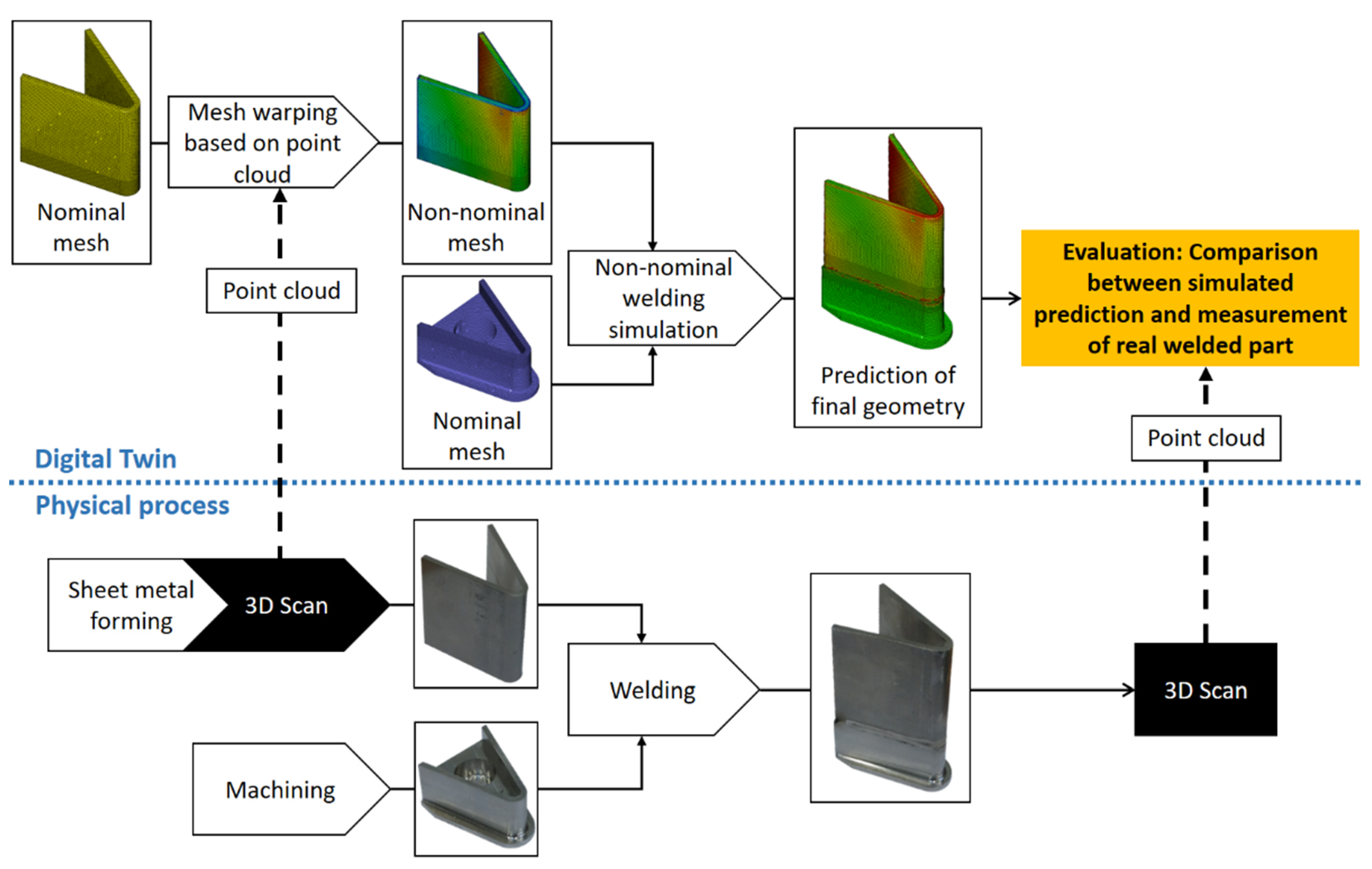
This paper proposes an analysis loop based on the digital twin paradigm, aimed at improving the geometrical quality of the final product by using welding simulation with a non-nominal virtual assembly. The main steps included in the method are data collection, creation of virtual parts, virtual assembly, welding simulation, and evaluation of final geometrical quality, as seen in
Figure 2.
During an assembly process, locating schemes are used to define the position of each part in an assembly. The locating scheme locks a part in the six degrees of freedom: three translations and three rotations. When designing a fixture for a manufacturing process, the position of a part is completely defined by six locating points. If further contact points such as supports or clamps are used, the locating scheme becomes over-defined, meaning that the part will need to deform in some way in order to meet all contact points. In a simulated environment, this requires a non-rigid model that can convert this deformation into a stress state in the part.
When new parts enter the process, their geometries are scanned and converted into discrete surface points. During the measurement, it is important that the parts are positioned using the same locating scheme as the rest of the manufacturing process. When the surface measurements have been collected, the next step is to use them to create virtual representations of the parts with the same geometrical variation as their physical counterparts. This is done by warping a nominal, meshed CAD model to match the measured surface points. To get the correct geometrical variation on all surfaces of the virtual model, the measured surface points must be correctly positioned. The locating points used in the fixture for measurement and welding are identified in the set of measurement points and the nominal CAD model. These points are then aligned in their respective directions according to the pre-defined locating scheme to ensure correct positioning. Once the CAD model and the measurement points are aligned, the CAD model is warped by moving each nominal node in the mesh to the nearest measurement point and adapting the mesh accordingly.
The next step is to build a virtual assembly using the non-nominal models of the parts. The models are positioned using the locating scheme for each part, and clamping forces are applied to match the weld fixture. This virtual assembly shows how the unique combination of geometrical variation in the parts affect the assembly, revealing issues such as propagating variation and alignment quality in the interfaces. When the virtual assembly is done and clamping forced have been applied on the mesh, a welding simulation is conducted to show how the assembly will react when heat is applied and material is melted at the weld seams. Settings such as weld sequence and weld parameters are chosen in the simulation according to the real welding process.
Once welding simulation has been applied at each weld seam, the result shows how the assembly will behave with the current geometrical conditions and process settings. These specific conditions can be evaluated based on how they affect the geometrical quality of the final welded assembly, and potential changes to process settings can be made accordingly before the real process is initiated. The loop of changing settings and evaluating final product geometry can be performed iteratively to identify process settings that yield better geometrical quality.
In order for this method to be feasible, two things are required from the non-nominal welding simulation. First, it needs to be accurate enough to provide useful results for the evaluation of final geometrical quality. Secondly, it needs to be fast enough to allow for evaluation of multiple process configurations in order to find the optimal settings, without delaying the physical production process while simulations are completed. The right balance between computation time and simulation accuracy depends on the tolerances and requirements as well as the production rate of the product. This balance must be attained in order for a digital twin for manufacturing to be feasible.
5. Case Study
The case study is aimed at evaluating the feasibility of non-nominal welding simulation in the context of a digital twin running in a realistic industrial production environment. As previously stated, both simulation accuracy and speed need to be evaluated. The study is based on an example from the aerospace industry, applying the same type of operations as are used in the manufacturing of modern aircraft engine components. All simulations are done in the RD&T software, which, in this use case, provides functionality for measurement data analysis, variation simulation, and non-nominal welding simulation. The scope of the case study based on the previously shown digital twin functionality is shown in
Figure 3. Five assemblies are welded in total, to account for individual differences between ingoing parts.
In this study, two parts are joined using laser welding, as shown in
Figure 4. Both parts are made from Alloy 718, a nickel-based heat resistant material common in aerospace components. The five assemblies are manufactured using the same geometrical specifications and process parameters. The first part (Part 1) is created from a machining process. The second part (Part 2) is made from a piece of sheet metal with a thickness of 2.54 mm, which has been formed into a V-shaped geometry by bending it at the middle. This causes a plastic deformation which results in residual stresses being built into the material. The edges at the top and bottom of part 2 are machined in order to remove the deformation caused by the bending. The combination of machined parts and formed sheet metal parts is typical for many aerospace engine components [
3]. Sheet metal enables the construction of light and strong turbine vanes, whereas machined parts often make up the hub and shroud of the turbine structure. The V-shaped geometry of part 2 is heavily simplified compared to the complex geometry of a turbine vane, but the main manufacturing challenges of formed sheet metal such as geometrical variation and residual stresses are still present in the test geometry.
One of the main goals of the case study is to evaluate how measurement data at the part level can help to predict variation at the assembly level. Since the sheet metal forming process is more sensitive to geometrical variation, measurement data is collected from part 2. This is done through optical 3D scanning, which generates a point cloud consisting of discrete points on the surface of the measured part. When the parts have been joined, 3D scanning is once again used to generate a new point cloud representing the finished welded assembly.
Once the point clouds have been collected, they need to be converted into geometries that are compatible with the virtual analysis process. Point clouds are stored as STL files that represent individual parts. The first step is to make sure that the STL files are correctly positioned by applying the relevant locating schemes. Locating points are placed on the STL files in the same locations as during manufacturing operations. These locating points are then aligned with a nominal CAD model of the corresponding part. Once the STL file has been properly aligned, the geometrical variation that is represented by the surface of the STL file needs to be transferred onto the simulation models. All simulations are done with meshed geometries consisting of tetrahedral elements. Using a proprietary algorithm in RD&T, each surface node on the meshed part is mapped in the normal direction onto the surface of the STL file and the mesh is warped so that the surface matches the scan data. In this way, the geometrical variation from the real part is transferred to a virtual model that is ready for use in a FEM simulation. A virtual assembly is created where the non-nominal geometries are mounted in a virtual welding fixture with the same locating scheme as the real welding fixture. This reveals properties that affect both geometrical quality and weld quality, such as the alignment and fit of the weld interfaces of the two parts.
Once the virtual assembly is complete, a 3D non-nominal welding simulation is conducted. In this case study, the SCV method is implemented due to its ability to handle non-nominal geometries while maintaining fast simulation speeds. Heat is applied in the weld seam based on the properties of the real welding procedure. Three different methods for welding simulation are used. The first is a traditional transient simulation where the heat is applied in small steps corresponding to one half of the mesh element size on the weld path, followed by a calculation of the mechanical response in each time step. A second simulation is conducted with the SCV method using a single melt zone for the entire weld, meaning that the melt zone is described in 2D and then applied to the 3D model. As shown in [
25], dividing the weld seam into multiple segments with different melt zones can give better predictions with the SCV method for some geometries. In the third simulation, the weld seam is divided into three segments with separate melt zones (see
Figure 5). In all three cases, the assumption is made that the heat-affected does not influence the welding deformation and that there are no residual stresses in the parts being welded.
Each Simulation is conducted with three different meshes with varying element size close to the weld seam, as seen in
Figure 6. The element size further away from the weld path is kept at 1 mm across all meshes, as the element size is more relevant close to the heat source. The results of the welding simulations are then compared to scan data from the corresponding finished welded assembly, as shown in
Figure 7. The distance between each surface node on the simulated mesh and the nearest surface point in the scan data is calculated normal to the surface. These distances are then converted into a single RMS (root mean square) value for each assembly, representing how well the simulated prediction matches the real geometry of the welded assembly.
6. Results and Discussion
As previously mentioned, a key factor for the envisioned digital twin implementation is the balance between simulation accuracy and speed. In order to assess the accuracy of the simulations, results are presented as RMS values based on the difference in millimeters bet ween simulation result and real result in a specific set of nodes, see
Figure 8. A contour plot showing the area that are used to calculate the RMS value. Grey areas do not affect the RMS value. RMS values have been chosen as a way of quantifying the difference between simulation and reality rather than using the maximum value in the chosen set of nodes. Since the measurement data is collected through 3D scanning, the measured variation in nodes close to the edge of the surface can contain inaccuracies and the maximum value may not be representative of the entire set of nodes. However, local errors will not affect RMS values significantly. All simulations have been run under identical conditions, so that the required time for each simulation can be presented as an indicator for relative simulation speed.
This study focuses on the influence of two parameters on the RMS value and the simulation time. The first parameter is the simulation method, which is varied between transient simulation, regular (single melt zone) SCV simulation, and segmented (multiple melt zones) SCV simulation. The other parameter is the element size close to the weld seam in the mesh that describes the parts during the simulation. Both of these parameters are related to the resolution of a welding simulation, i.e., how closely the virtual model approximates the real welded part. Higher resolution generally means higher computational cost, and often yields a more accurate result.
In
Table 1, the results of the case study are summarized. RMS values are presented for each of the five welded assemblies, showing how variation can affect the process. The lowest RMS value in each column, representing the lowest prediction error achieved for each assembly, has been underlined for clarity. RMS values for a nominal model with no simulation are also given as a reference point. The values referred to as “No simulation” describes the difference between a nominal virtual assembly that is free from variation and the real welded assembly. The difference between these RMS values and the RMS values achieved with simulation serves as an initial indicator for the performance of the simulation method. For each assembly, RMS values can be seen for each of the three welding simulation methods. To account for the effects of mesh resolution, each simulation method has been tested with three different element sizes.
Table 2 shows average and median RMS values based on the five assemblies, together with the average simulation time for each mesh and method.
When interpreting the results, both accuracy and simulation speed are important to the intended use case of a digital twin for manufacturing. Accuracy is indicated in this case study by the RMS values, where a lower value is related to higher simulation accuracy. RMS values should first be compared to the reference values labeled “no simulation”, in order to ensure that the simulations are delivering higher precision than the baseline, nominal model. The RMS values obtained from the nominal model with no simulation (the first row in
Table 1 and
Table 2) are higher than the RMS values obtained through non-nominal simulation in all cases, meaning that the non-nominal simulation setup used in this study has successfully predicted a part of the unique geometrical variation in all of the welded assemblies. This is an important initial result, since it reinforces the proposal of a digital twin for manufacturing that uses non-nominal welding simulation to predict final assembly variation. Measurement data shows that the welded assemblies experienced a shrinkage concentrated to the curved segment of the weld seam. This is reasonable since the melted zone is larger along the curved weld, causing more deformation. Overall, the results of the case study show that the proposed approach with non-nominal welding simulation is capable of predicting the behavior observed during real welding.
The case study consists of five assemblies that are manufactured to identical specifications. However, the results show that the assemblies differ from each other not only in the measured part geometries, but also in the prediction accuracy of the conducted welding simulations. This means that there are sources of variation in the manufacturing process that are not captured by the geometrical measurement data from the 3D scanning, otherwise, the prediction error would be equal for all five assemblies. To achieve consistent performance in a digital twin, more measurement data is needed in order to capture all relevant sources of variation. Geometrical data on the part level may not be sufficient.
The results show a significant reduction in simulation time for the SCV method when compared to transient simulations. As previously mentioned, simulation speed is crucial in a digital twin implementation. The prediction accuracy does suffer somewhat for the single segment SCV compared to transient simulation, which could be related to the weld seam properties in the curved segment of the weld path. Regular SCV simulation means that one set of welding parameters must be used for the entire weld, which is not ideal for welds with complex features. However, using the segmented SCV approach shows similar accuracy to the full transient simulation while still being significantly faster. For welds where the weld seam can be clearly divided into segments with distinct properties, the segmented SCV approach could be an ideal choice for simulations requiring high accuracy and speed.
Three different element sizes close to the weld are tested for each simulation conducted within the case study. In the case study, no clear differences in accuracy can be observed between the different elements sizes used. In this case, an even larger element size would not have yielded significantly faster simulations and has not been tested. The similarities between results could be due to the fact that the geometry used in the case study is relatively simple, with mostly straight lines and flat surfaces, except for a small, curved segment. The ideal element size may need to be selected individually based on the complexity of the geometry being simulated.
As previously mentioned, the difference in prediction accuracy between the five welded assemblies suggests that there are variation sources present in the manufacturing process that are not taken into account in the simulations done within this case study. Possible sources of prediction errors in the welding simulation are summarized below:
The sheet metal forming process used to produce Part 2 causes plastic deformation of the material, leading to residual stresses in the part. These residual stresses have an effect on the outcome of the welding process, since the added heat causes a relaxation in the material which will lead to deformation of the part through the release of residual stresses.
This case study relies on measurement data collected through 3D scanning. The natural limitations of 3D scanning such as measurement errors near sharp edges on the part may cause inaccuracies in the measured part geometries. Since the welding simulation uses this data to predict the geometry of the final assembly, measurement inaccuracies may propagate into a prediction error.
The welding simulation assumes that Part 2 is placed in a fully nominal position in relation to Part 1 at the start of the welding process. Variation in the positioning of the parts before welding would lead to geometrical variation in the final assembly which is not taken into account in the welding simulation, possibly leading to a prediction error.
The melted zone in the weld seam is calculated based on the effect and speed of the weld gun. Variation in the welding process such as effect losses or movement errors in the weld gun would cause an inaccurate prediction of the melted zone, leading to a prediction error in the calculated welding deformation.
The material in the parts is assumed to be homogeneous and isotropic, and free from impurities and inclusions. Geometrical variation caused by, i.e., varying grain size or changes in the heat-affected zone during welding are not taken into account in the welding simulation and may cause prediction errors.
Further research should focus on an expanded analysis of a digital twin for manufacturing. The accuracy of the digital twin could be improved by implementing additional measurement data from the parts according to the suggested error sources listed above. In order to complete the analysis loop suggested in
Figure 2, a methodology is required for translating the output from the welding simulation into an adaptive process adjustment. The RMS value used in the case study could be a good target value for optimizing the process by minimizing variation in the weld interfaces before welding. Another target value for optimization could be the amount of clamping force that is required to force a part into a nominal fixture, which would reduce the internal stresses in the assembly.
7. Conclusions
In this paper, a method for managing assembly variation using a digital twin is proposed. The method includes in-line data collection, non-nominal virtual assembly, non-nominal welding simulation, and adaptive process adjustments. A case study is presented where the data collection and analysis steps of the method are applied to a two part assembly. The output from the simulations is compared to real welding results in order to assess the viability of the method for a digital twin implementation. Results show that the non-nominal welding simulation used in the case study does capture the behavior of its physical counterpart, showing that it is able to predict the welding deformation of a non-nominal part before it is welded. Using a full transient simulation yielded high accuracy and low speed, the regular SCV simulation method increases speed significantly, whereas accuracy suffers somewhat. The segmented SCV method yielded the same speed as regular SCV, whereas the accuracy is roughly equal to a transient simulation for the geometry used in this case study. Among the methods evaluated in this paper, the segmented SCV method is therefore the most suitable approach for a digital twin for manufacturing.
These results are an important contribution towards the development of a digital twin for high precision manufacturing, showing that it is possible to conduct fast and accurate non-nominal welding simulations by using data from a 3D scanning process. This is an important requirement in order to enable the analysis loop of the digital twin as shown in
Figure 2. As the aerospace industry continues to strive towards lower fuel burn and reduced carbon footprint, new manufacturing methods are needed that can reliably deliver the precision that will be required from components such as engine structures. A digital twin would increase the capability of existing manufacturing processes, making it possible to produce parts and products with lower tolerances and higher precision.
Author Contributions
Conceptualization, H.H., S.C., R.S., and K.W.; methodology, H.H.; software, H.H.; validation, H.H., S.C., R.S., and K.W.; formal analysis, H.H.; investigation, H.H.; resources, H.H., S.C., R.S., and K.W.; data curation, H.H.; writing—original draft preparation, H.H.; writing—review and editing, H.H., S.C., R.S., and K.W.; visualization, H.H.; supervision, S.C., R.S., and K.W.; project administration, H.H., S.C., R.S., and K.W.; funding acquisition, S.C. All authors have read and agreed to the published version of the manuscript.
Funding
This work was funded by support from the Swedish Governmental Agency of Innovation Systems (VINNOVA) and the NFFP7 program.
Institutional Review Board Statement
Not applicable.
Informed Consent Statement
Not applicable.
Data Availability Statement
The data presented in this study were generated using the geometry assurance software RD&T (
http://rdnt.se/ accessed on 23 June 2022). The final data presented in this study is available on request from the corresponding author.
Acknowledgments
The funding from the Swedish Governmental Agency of Innovation Systems (VINNOVA) and the NFFP7 program is gratefully acknowledged.
Conflicts of Interest
The authors declare no conflict of interest.
References
- Marziale, M.; Polini, W. Review of variational models for tolerance analysis of an assembly. Proc. Inst. Mech. Eng. Part B J. Eng. Manuf. 2011, 225, 305–318. [Google Scholar] [CrossRef]
- Falgarone, H.; Thiébaut, F.; Coloos, J.; Mathieu, L. Variation simulation during assembly of non-rigid components. Realistic assembly simulation with ANATOLEFLEX software. Procedia Cirp 2016, 43, 202–207. [Google Scholar] [CrossRef]
- Runnemalm, H.; Tersing, H.; Isaksson, O. Virtual manufacturing of light weight aero engine components. In Proceedings of the International Symposium on Air Breathing Engines, Montreal, QC, Canada, 7–11 September 2009. [Google Scholar]
- Forslund, A.; Lorin, S.; Lindkvist, L.; Wärmefjord, K.; Söderberg, R. Minimizing Weld Variation Effects Using Permutation Genetic Algorithms and Virtual Locator Trimming. J. Comput. Inf. Sci. Eng. 2018, 18, 041010. [Google Scholar] [CrossRef]
- Hultman, H.; Cedergren, S.; Söderberg, R.; Wärmefjord, K. Towards a Digital Twin Setup for Individualized Production of Fabricated Components. In Proceedings of the ASME International Mechanical Engineering Congress and Exposition, Online, 1–5 November 2021; p. V02BT02A075. [Google Scholar]
- Hultman, H.; Cedergren, S.; Söderberg, R.; Wärmefjord, K. Identification of Variation Sources for High Precision Fabrication in a Digital Twin Context. In Proceedings of the ASME International Mechanical Engineering Congress and Exposition, Online, 16–19 November 2020; p. V02BT02A058. [Google Scholar]
- Glaessgen, E.H.; Stargel, D.S. The digital twin paradigm for future NASA and U.S. Air force vehicles. In Proceedings of the Collection of Technical Papers—AIAA/ASME/ASCE/AHS/ASC Structures, Structural Dynamics and Materials Conference, Honolulu, HI, USA, 23–26 April 2012. [Google Scholar]
- Tao, F.; Zhang, H.; Liu, A.; Nee, A.Y. Digital twin in industry: State-of-the-art. IEEE Trans. Ind. Inform. 2018, 15, 2405–2415. [Google Scholar] [CrossRef]
- Schleich, B.; Anwer, N.; Mathieu, L.; Wartzack, S. Shaping the digital twin for design and production engineering. CIRP Ann. 2017, 66, 141–144. [Google Scholar] [CrossRef]
- Kritzinger, W.; Karner, M.; Traar, G.; Henjes, J.; Sihn, W. Digital Twin in manufacturing: A categorical literature review and classification. IFAC-PapersOnLine 2018, 51, 1016–1022. [Google Scholar] [CrossRef]
- Zhou, G.; Zhang, C.; Li, Z.; Ding, K.; Wang, C. Knowledge-driven digital twin manufacturing cell towards intelligent manufacturing. Int. J. Prod. Res. 2020, 58, 1034–1051. [Google Scholar] [CrossRef]
- Schleich, B.; Dittrich, M.-A.; Clausmeyer, T.; Damgrave, R.; Erkoyuncu, J.A.; Haefner, B.; de Lange, J.; Plakhotnik, D.; Scheidel, W.; Wuest, T. Shifting value stream patterns along the product lifecycle with digital twins. Procedia CIRP 2019, 86, 3–11. [Google Scholar] [CrossRef]
- Roy, R.B.; Mishra, D.; Pal, S.K.; Chakravarty, T.; Panda, S.; Chandra, M.G.; Pal, A.; Misra, P.; Chakravarty, D.; Misra, S. Digital twin: Current scenario and a case study on a manufacturing process. Int. J. Adv. Manuf. Technol. 2020, 107, 3691–3714. [Google Scholar] [CrossRef]
- Lindgren, L.-E. Modelling for residual stresses and deformations due to welding: “knowing what isn’t necessary to know”. In Proceedings of the International Seminar on Numerical Analysis of Weldability, London, United Kingdom, 1–2 October 2001; pp. 491–518. [Google Scholar]
- Goldak, J.A.; Akhlaghi, M. Computational Welding Mechanics; Springer Science & Business Media: Berlin/Heidelberg, Germany, 2005. [Google Scholar]
- Pahkamaa, A.; Wärmefjord, K.; Karlsson, L.; Söderberg, R.; Goldak, J. Combining variation simulation with welding simulation for prediction of deformation and variation of a final assembly. J. Comput. Inf. Sci. Eng. 2012, 12, 021002. [Google Scholar] [CrossRef] [Green Version]
- Xiong, C.; Rong, Y.; Koganti, R.; Zaluzec, M.; Wang, N. Geometric variation prediction in automotive assembling. Assem. Autom. 2002, 22, 260–269. [Google Scholar] [CrossRef]
- Lee, D.; Kwon, K.E.; Lee, J.; Jee, H.; Yim, H.; Cho, S.W.; Shin, J.-G.; Lee, G. Tolerance analysis considering weld distortion by use of pregenerated database. J. Manuf. Sci. Eng. 2009, 131, 041012. [Google Scholar] [CrossRef]
- Ueda, Y.; Yuan, M.G. A Predicting Method of Welding Residual Stress Using Source of Residual Stress (Report III): Prediction of Residual Stresses in T-and I-joints Using Inherent Strains (Mechanics, Strength & Structural Design). Trans. JWRI 1993, 22, 157–168. [Google Scholar]
- Camilleri, D.; Comlekci, T.; Gray, T.G. Thermal distortion of stiffened plate due to fillet welds computational and experimental investigation. J. Therm. Stresses 2006, 29, 111–137. [Google Scholar] [CrossRef]
- Bachorski, A.; Painter, M.; Smailes, A.; Wahab, M.A. Finite-element prediction of distortion during gas metal arc welding using the shrinkage volume approach. J. Mater. Processing Technol. 1999, 92, 405–409. [Google Scholar] [CrossRef]
- Sulaiman, M.S.; Manurung, Y.H.; Haruman, E.; Rahim, M.R.A.; Redza, M.R.; Lidam, R.N.A.; Abas, S.K.; Tham, G.; Chau, C.Y. Simulation and experimental study on distortion of butt and T-joints using WELD PLANNER. J. Mech. Sci. Technol. 2011, 25, 2641–2646. [Google Scholar] [CrossRef]
- Lorin, S.; Cromvik, C.; Edelvik, F.; Lindkvist, L.; Söderberg, R. Variation Simulation of Welded Assemblies Using a Thermo-Elastic Finite Element Model. J. Comput. Inf. Sci. Eng. 2014, 14, 031003. [Google Scholar] [CrossRef]
- Lorin, S.; Cromvik, C.; Edelvik, F.; Lindkvist, L.; Söderberg, R. On the Robustness of the Volumetric Shrinkage Method in the Context of Variation Simulation. In Proceedings of the ASME 2014 International Mechanical Engineering Congress and Exposition, Montreal, QC, Canada, 14 November 2014. [Google Scholar]
- Lorin, S.; Cromvik, C.; Edelvik, F.; Lindkvist, L.; Söderberg, R.; Wärmefjord, K. Simulation of non-nominal welds by resolving the melted zone and its implication to variation simulation. In Proceedings of the ASME 2014 International Design Engineering Technical Conferences and Computers and Information in Engineering Conference, Buffalo, NY, USA, 17–20 August 2014. [Google Scholar]
- Schleich, B.; Anwer, N.; Mathieu, L.; Wartzack, S. Skin model shapes: A new paradigm shift for geometric variations modelling in mechanical engineering. Comput.-Aided Des. 2014, 50, 1–15. [Google Scholar] [CrossRef]
| Publisher’s Note: MDPI stays neutral with regard to jurisdictional claims in published maps and institutional affiliations. |
© 2022 by the authors. Licensee MDPI, Basel, Switzerland. This article is an open access article distributed under the terms and conditions of the Creative Commons Attribution (CC BY) license (https://creativecommons.org/licenses/by/4.0/).


