
Preliminary Sizing of the Electrical Motor and Housing of Electromechanical Actuators Applied on the Primary Flight Control System of Unmanned Helicopters


Abstract
:1. Introduction
1.1. Context
1.1.1. Helicopter Dronization
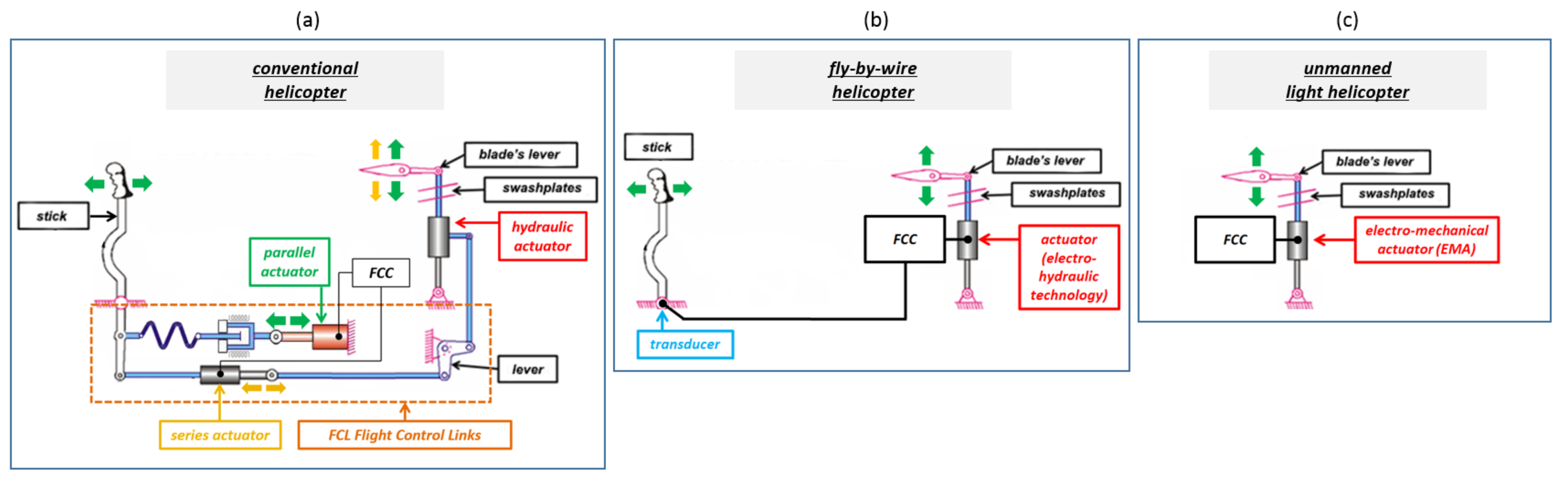
1.1.2. Primary Flight Control Systems: From Hydraulic to Electromechanical Technologies
1.1.3. Business Need
1.2. Helicopter Specificities
1.3. Electromechanical Actuators
1.4. Preliminary Sizing Method
1.5. Objective and Outline
2. Global Methodology
- The actuation need must be understood. Flight mission profiles are analyzed. An equivalent actuator specification is synthesized, with key design values corresponding to component specificities.
- Each actuator component is modeled according to the available inputs.
- All models are set up into a sizing loop. An optimization algorithm is implemented with the objective of mass minimization.

3. Mission Profile Analysis
3.1. Methodology
- Considering the actuator architecture and components to extract a list of key parameters driving the design, called key design drivers.
- Preparing the data to be analyzed (mission profiles) by filtering and transforming within the temporal or frequency domains.
- Linking the data to the component key parameters, setting up the mathematical indicators to estimate over mission profiles. Each design driver has its own representative indicator(s).
- The evaluation of indicators over mission profiles to develop the final EMA specification.

3.2. Estimation over Real Mission Profiles
4. Models for the Preliminary Sizing of EMA
4.1. Modeling Overview
- The component level: It deals with the determination of component characteristics from a reduced number of parameters to facilitate the optimization. The models involved in it are called the estimation models (Figure 6).
- The system level: It deals with interactions between components, operational scenarios, and component operational limits. The models involved in it are called simulation models and evaluation models (Figure 6).

4.2. Need of Estimation Models and Approach
5. Scaling Laws
5.1. Fundamentals
- Geometric similarity: all the dimensions of the considered component to all the lengths of the component used for reference are constant. Thus, all corresponding aspect ratios are constant: .
- Uniqueness of design drivers: only one main dominant physical phenomenon drives the evolution of the component secondary characteristic y. Thus, in most cases, there is not anymore dependency with any (function g, Equation (3)).
- Material similarity: all material properties are assumed to be identical to those of the component used for reference. Thus, all corresponding scaling ratios are equal to 1: .
5.2. Electrical Motor Scaling Laws
6. Regression Models
6.1. Introduction
6.2. Prior Considerations
6.3. Hypothesis
6.4. Problem Formulation
6.5. Dimensional Analysis
6.6. FEM Software Model
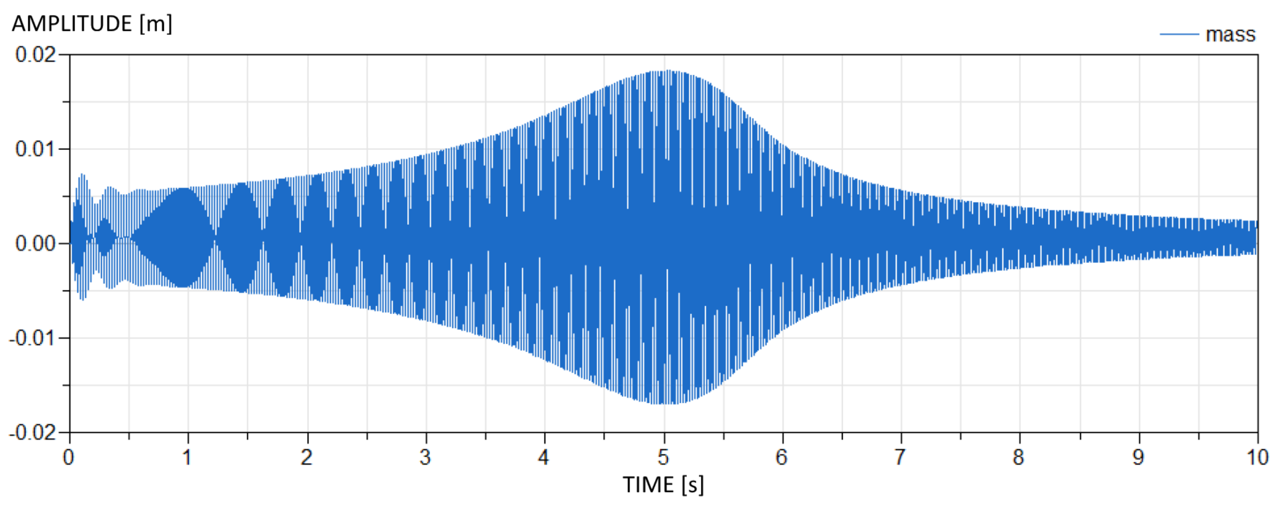
- The resonance frequency or the resonance angular frequency .
- The modal form characterized by a maximal displacement .
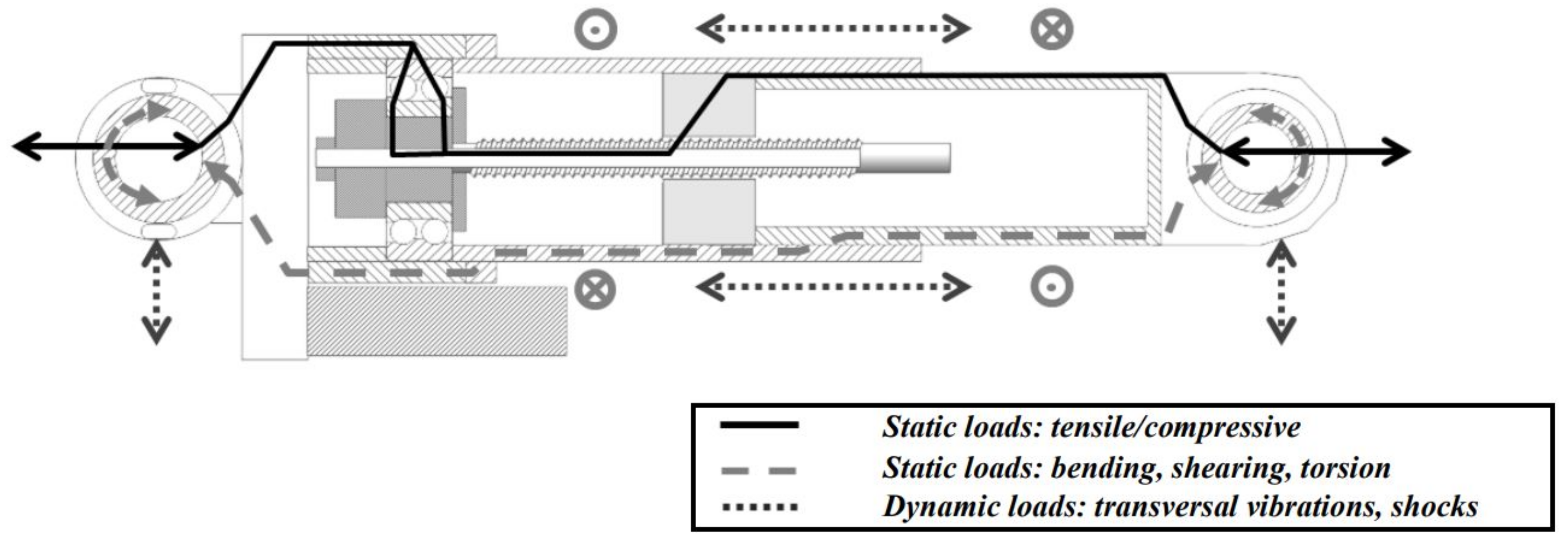
- The corresponding maximum stress . The maximum stress is identified to be on the output rod tube ( thickness).
6.7. DOE and Surrogate Synthesis
6.8. Validation
7. Results
7.1. Arbitrary Sizings
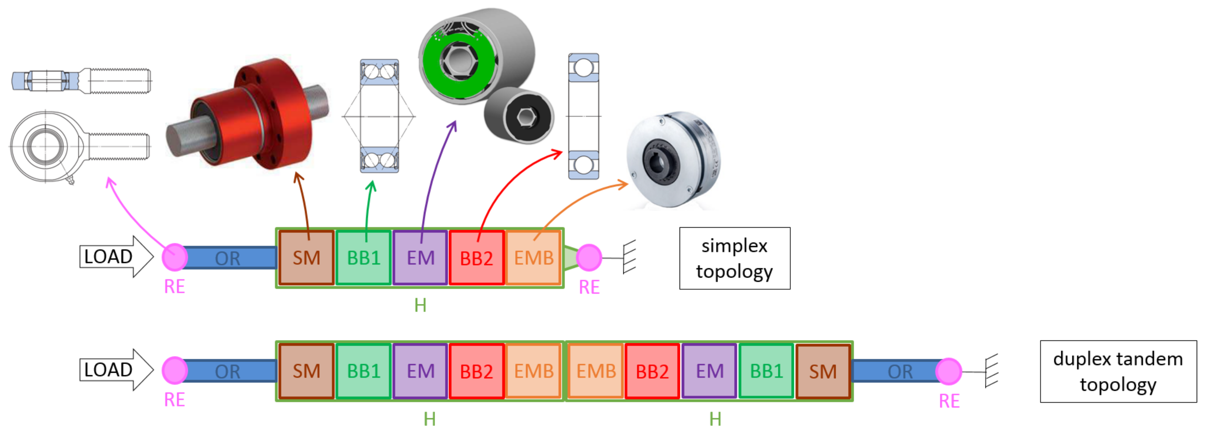
7.2. Sizing of Redundant Topologies of Actuation
7.3. Sizing of Main and Tail Rotor Actuators
8. Discussion
Author Contributions
Funding
Institutional Review Board Statement
Informed Consent Statement
Data Availability Statement
Acknowledgments
Conflicts of Interest
Nomenclature
| Symbol | Unit | Name | Symbol | Unit | Name |
| Section 3 | |||||
| m · s | acceleration on mission profiles | N | load on mission profiles | ||
| s | m | stroke | m · s | speed on mission profiles | |
| N· m · s | power rate | N· m · s | mean power rate | ||
| m · s | acceleration at maximum power rate | N | load at maximum power rate | ||
| Section 5 | |||||
| - | scaling ratio | - | -number | ||
| [x] | characteristic of component of reference used in scaling law | ||||
| d | m | dimension or diameter | p | [p] | material property |
| L | m | characteristic length | M | kg | mass |
| kg · m | density | V | m | volume | |
| T | m · N | torque | m · N | peak torque | |
| m · N · W | copper losses coefficient | rad · s · W | iron losses coefficient | ||
| rad · s | electrical speed | rad · s | angular speed | ||
| m · N · W | motor constant | Q | W | heat | |
| Section 6 | |||||
| x | m | vibratory displacement amplitude | hz | first resonance mode frequency | |
| a | m · s | amplitude of sinusoidal vibratory acceleration | |||
| rad · s | angular frequency | m | actuator total length | ||
| m | housing thickness | m | output rod thickness | ||
| m | roller-screw nut diameter | m | roller-screw nut length | ||
| kg | equivalent mass | N · m | equivalent stiffness | ||
| N · m · s | equivalent damping | - | equivalent damping coefficient | ||
| [x] | value of x at first resonance mode | F | N | excitation load applied on | |
| U | m | displacement of | u | m | actuator deflection |
| V | m· s | speed of | v | m·s | actuator deflection speed |
| Pa | actuator housing stress | - | actuator quality factor | ||
| E | Pa | Young’s modulus of actuator material | kg· m | density of actuator material | |
Abbreviations
| BB1 | Angular Contact Double-row Ball Bearing |
| BB2 | Deep Groove Single-row Ball Bearing |
| DoE | Design of Experiment |
| DDV | Direct Drive Valve |
| EM | Electrical Motor (PMSM) |
| EMA | Electromechanical Actuator |
| EMB | Electromagnetic Brake |
| FCC | Flight Control Computer |
| FCL | Flight Control Links |
| H | Housing |
| IDF | Individual Disciplinary Feasible |
| KDD | Key Design Driver |
| MDO | Multidisciplinary Design Optimization |
| MRA | Main Rotor Actuator |
| OPV | Optionally Piloted Vehicle |
| OR | Output Rod |
| PFCS | Primary Flight Control System |
| RE | Rod End |
| RMC | Root Mean Cube |
| RMS | Root Mean Square |
| RSM | Response Surface Model |
| SFCS | Secondary Flight Control System |
| SM | Screw Mechanism |
| TRA | Tail Rotor Actuator |
| UAM | Urban Air Mobility |
| UAS | Unmanned Aerial System |
| UAV | Unmanned Aerial Vehicle |
| VPLM | Variable Power-Law Metamodel |
| VTOL | Vertical Take-off Landing |
Appendix A. Surrogate Model: Housing of the Tandem Topology of Actuation
References
- Qiao, G.; Liu, G.; Shi, Z.; Wang, Y.; Ma, S.; Lim, T.C. A review of electromechanical actuators for More/All Electric aircraft systems. Proc. Inst. Mech. Eng. Part J. Mech. Eng. Sci. 2018, 232, 4128–4151. [Google Scholar] [CrossRef]
- Cochoy, O.; Carl, U.B.; Thielecke, F. Integration and control of electromechanical and electrohydraulic actuators in a hybrid primary flight control architecture. In Proceedings of the International Conference on Recent Advances in Aerospace Actuation Systems and Components (R3ASC), Toulouse, France, 13–15 June 2007; INSA: Toulouse, France, 2007; pp. 1–8. [Google Scholar]
- Roussel, J.; Budinger, M.; Ruet, L. Unmanned helicopter flight control actuator specification through mission profile analysis. In Proceedings of the IOP Conference Series: Materials Science and Engineering; IOP Publishing: Bristol, UK, 2022; Volume 1226, p. 012100. Available online: https://iopscience.iop.org/article/10.1088/1757-899X/1226/1/012100/meta (accessed on 18 August 2022).
- Raletz, R. Basic Theory of the Helicopter; CEPADUES: Toulouse, France, 2010; ISBN 9782854289374. [Google Scholar]
- FAA. Helicopter Flying Handbook. US Department of Transportation: Washington, DC, USA, 2019. Available online: https://www.faa.gov/sites/faa.gov/files/regulations_policies/handbooks_manuals/aviation/helicopter_flying_handbook/helicopter_flying_handbook.pdf (accessed on 30 July 2022).
- Maré, J.C. Aerospace Actuators 2: Signal-by-Wire and Power-by-Wire; ISTE Group: London, UK, 2017; Volume 2. [Google Scholar]
- RTCA. Environmental Conditions and Test Procedures for Airborne Equipment, DO-160E, EUROCAE ED-14E; RTCA: Washington, DC, USA, 2005. [Google Scholar]
- Mazzoleni, M.; Di Rito, G.; Previdi, F. Electro-Mechanical Actuators for the More Electric Aircraft; Springer: Berlin/Heidelberg, Germany, 2021. [Google Scholar]
- Liscouët, J.; Maré, J.C.; Budinger, M. An integrated methodology for the preliminary design of highly reliable electromechanical actuators: Search for architecture solutions. Aerosp. Sci. Technol. 2012, 22, 9–18. Available online: https://scholar.google.fr/citations?view_op=view_citation&hl=fr&user=nkGEGZgAAAAJ&citation_for_view=nkGEGZgAAAAJ:ufrVoPGSRksC (accessed on 30 July 2022). [CrossRef]
- Andersson, J.; Krus, P.; Nilsson, K. Optimization as a support for selection and design of aircraft actuation systems. In Proceedings of the 7th AIAA/USAF/NASA/ISSMO Symposium on Multidisciplinary Analysis and Optimization, St. Louis, MO, USA, 2–4 September 1998; p. 4887. [Google Scholar]
- Jiao, Z.; Yu, B.; Wu, S.; Shang, Y.; Huang, H.; Tang, Z.; Wei, R.; Li, C. An intelligent design method for actuation system architecture optimization for more electrical aircraft. Aerosp. Sci. Technol. 2019, 93, 105079. [Google Scholar] [CrossRef]
- Roos, F. On Design Methods for Mechatronics: Servo Motor and Gearhead. Ph.D. Thesis, Royal Institute of Technology, Stockholm, Sweden, 2005. [Google Scholar]
- Roos, F.; Johansson, H.; Wikander, J. Optimal selection of motor and gearhead in mechatronic applications. Mechatronics 2006, 16, 63–72. [Google Scholar] [CrossRef]
- Pfennig, M.; Carl, U.B.; Thielecke, F. Recent advances towards an integrated and optimized design of high lift actuation systems. SAE Int. J. Aerosp. 2010, 3, 55. [Google Scholar] [CrossRef]
- Wu, S.; Yu, B.; Jiao, Z.; Shang, Y.; Luk, P. Preliminary design and multi-objective optimization of electro-hydrostatic actuator. Proc. Inst. Mech. Eng. Part J. Aerosp. Eng. 2017, 231, 1258–1268. [Google Scholar] [CrossRef]
- Raymer, D. Aircraft Design: A Conceptual Approach; American Institute of Aeronautics and Astronautics, Inc.: Reston, VA, USA, 2012. [Google Scholar]
- Budinger, M.; Reysset, A.; Ochotorena, A.; Delbecq, S. Scaling laws and similarity models for the preliminary design of multirotor drones. Aerosp. Sci. Technol. 2020, 98, 105658. [Google Scholar] [CrossRef]
- Massachusetts I.o.T. Thermodynamic and Propulsion—Aircraft Engine Performance— Performance of Propellers. Online MIT Resource. 2022. Available online: https://web.mit.edu/16.unified/www/FALL/thermodynamics/notes/node86.html (accessed on 30 July 2022).
- McCormick, B.W.; Aljabri, A.S.; Jumper, S.J.; Martinovic, Z.N. The Analysis of Propellers Including Interaction Effects. NASA Scientific and Technical Information Facility. 1979. Available online: https://www.researchgate.net/publication/23913137_The_Analysis_of_Propellers_Including_Interaction_Effects:2022/07 (accessed on 30 July 2022).
- Saerens, E.; Crispel, S.; Garcia, P.L.; Verstraten, T.; Ducastel, V.; Vanderborght, B.; Lefeber, D. Scaling laws for robotic transmissions. Mech. Mach. Theory 2019, 140, 601–621. [Google Scholar] [CrossRef]
- Papalambros, P.Y.; Wilde, D.J. Principles of Optimal Design: Modeling and Computation, 2nd ed.; Cambridge University Press: Cambridge, UK; New York, NY, USA, 2000. [Google Scholar]
- Martins, J.R.; Lambe, A.B. Multidisciplinary design optimization: A survey of architectures. AIAA J. 2013, 51, 2049–2075. [Google Scholar] [CrossRef]
- Budinger, M.; Reysset, A.; Halabi, T.E.; Vasiliu, C.; Maré, J.C. Optimal preliminary design of electromechanical actuators. Proc. Inst. Mech. Eng. Part G J. Aerosp. Eng. 2014, 228, 1598–1616. [Google Scholar] [CrossRef] [Green Version]
- Reysset, A.; Budinger, M.; Maré, J.C. Computer-aided definition of sizing procedures and optimization problems of mechatronic systems. Concurr. Eng. 2015, 23, 320–332. [Google Scholar] [CrossRef]
- Delbecq, S.; Budinger, M.; Reysset, A. Benchmarking of monolithic MDO formulations and derivative computation techniques using OpenMDAO. Struct. Multidiscip. Optim. 2020, 62, 645–666. [Google Scholar] [CrossRef]
- Jaafar, A. Analysis of Mission Profiles and Environment Variables for Integration into the Systemic Design Processus. Ph.D. Thesis, INP, Toulouse, France, 2011. [Google Scholar]
- Reysset, A. Preliminary Design of Electromechanical Actuators—Tools to Support the Specification and the Generation of Sizing Procedures for the Optimization. Ph.D. Thesis, INSA, Toulouse, France, 2015. [Google Scholar]
- Hehenberger, P.; Poltschak, F.; Zeman, K.; Amrhein, W. Hierarchical design models in the mechatronic product development process of synchronous machines. Mechatronics 2010, 20, 864–875. [Google Scholar] [CrossRef]
- Van Groesen, E.; Molenaar, J. Continuum Modeling in the Physical Sciences; SIAM: Bangkok, Thailand, 2007; Volume 13, pp. 1–29. [Google Scholar]
- Holmes, M.H. Dimensional Analysis (Chapter). In Introduction to the Foundations of Applied Mathematics; Springer: Berlin/Heidelberg, Germany, 2019; pp. 1–47. [Google Scholar]
- Sanchez, F.; Budinger, M.; Hazyuk, I. Dimensional analysis and surrogate models for the thermal modeling of Multiphysics systems. Appl. Therm. Eng. 2017, 110, 758–771. [Google Scholar] [CrossRef]
- Lacey, D.; Steele, C. The use of dimensional analysis to augment design of experiments for optimization and robustification. J. Eng. Des. 2006, 17, 55–73. [Google Scholar] [CrossRef]
- Budinger, M.; Liscouët, J.; Hospital, F.; Maré, J. Estimation models for the preliminary design of electromechanical actuators. Proc. Inst. Mech. Eng. Part J. Aerosp. Eng. 2012, 226, 243–259. [Google Scholar] [CrossRef]
- Jufer, M. Design and losses-scaling law approach. In Proceedings of the Nordic Research Symposium Energy Efficient Electric Motors and Drives, Skagen, Denmark, 12 16 August 1996; pp. 21–25. Available online: https://www.researchgate.net/profile/Marcel-Jufer/publication/288811698_Design_and_Losses-Scaling_Law_Approach/links/6146d76e3c6cb310697a4154/Design-and-Losses-Scaling-Law-Approach.pdf (accessed on 18 August 2022).
- PARKER. Frameless Low Cogging Servo Motors—NK Series. 2022. Available online: https://ph.parker.com/us/en/frameless-low-cogging-servo-motors-nk-series/nk630esrr1000 (accessed on 30 July 2022).
- KOLLMORGEN. RBE Series Brushless Motors for Frameless DDR (Direct Drive Rotary) Motor Applications. 2003. Available online: http://www.kollmorgen.com/ (accessed on 30 July 2022).
- Grellet, G. TI Technics of the Engineer—d3450v1—Losses in the Spinning Machines; Technics of the Engineer Editions: Saint-Denis, France, 1989. [Google Scholar]
- Budinger, M.; Reysset, A.; Maré, J.C. Preliminary design of aerospace linear actuator housings. Aircr. Eng. Aerosp. Technol. Int. J. 2015, 87, 224–237. [Google Scholar]
- EASA. Certification Specifications and Acceptable Means of Compliance for Large Aeroplanes CS-25 Amendment 4; EASA: Cologne, Germany, 2007. [Google Scholar]
- Nicolas, M. Continuum and Discrete Mechanics. Available online: https://cel.archives-ouvertes.fr/cel-00612360v1/document (accessed on 30 July 2022).
- Spencer, A.J.M. Continuum Mechanics; Courier Corporation: North Chelmsford, MA, USA, 2004; ISBN 978-0486435947. [Google Scholar]
- Naubert, A.; Bachmann, M.; Binz, H.; Christmann, M.; Perni, F.; Toro, S. Disconnect device design options for jam-tolerant EMAs. In Proceedings of the International Conference on Recent Advances in Aerospace Actuation Systems and Components (R3ASC), Toulouse, France, 16–17 March 2016; INSA Toulouse: Toulouse, France, 2016; pp. 187–192. [Google Scholar]
- Seemann, S.; Christmann, M.; JȨnker, P. Control and monitoring concept for a fault-tolerant electromechanical actuation system, EADS Innovation Work. In Proceedings of the International Conference on Recent Advances in Aerospace Actuation Systems and Components (R3ASC), Toulouse, France, 13–14 June 2012; INSA Toulouse: Toulouse, France, 2012; pp. 39–43. [Google Scholar]
- Delbecq, S.; Budinger, M.; Ochotorena, A.; Reysset, A.; Defaÿ, F. Efficient sizing and optimization of multirotor drones based on scaling laws and similarity models. Aerosp. Sci. Technol. 2020, 102, 105873. [Google Scholar] [CrossRef]
- Liscouet-Hanke, S. A Model-Based Methodology for Integrated Preliminary Sizing and Analysis of Aircraft Power System Architectures. Ph.D. Thesis, Institut National des Sciences Appliquées de Toulouse, Toulouse, France, 2008. [Google Scholar]


| Measures | Indicator | Ratio MRA/TRA [-] |
|---|---|---|
| position | stroke max | 1.1 |
| equivalent distance travelled | 0.5 | |
| speed max | 1.1 | |
| speed iron | 0.5 | |
| acceleration max | 0.6 | |
| acceleration rms | 0.7 | |
| load | load max | 7.0 |
| load rms | 15.1 | |
| load rmc | 13.6 | |
| position & load | power rate mean | 4.6 |
| power rate max | 3.0 | |
| pair | (0.6; 4.7) |
| Domain | Indicator | Unit | MRA | TRA |
|---|---|---|---|---|
| pitting fatigue | - | 28 | 5 |
| Component Characteristics | Unit | Scaling Law | |||
|---|---|---|---|---|---|
| ELECTRICAL MOTOR (EM) (brushless, cylindrical) | |||||
| Note: error estimations performed using PARVEX NK and KOLLMORGEN RBE catalogue ranges () | |||||
| key design parameter | |||||
| continuous torque | Nm | - | - | ||
| motor constant | (N· m)/W | - | - | ||
| integration parameter | |||||
| dimensions () | m | 1.1% | 7.5% | ||
| mass | kg | 6.4% | 3.9% | ||
| simulation parameter | |||||
| inertia | kg· m | 0.1% | 20% | ||
| copper coef. | W/(Nm) | 13% | 16% | ||
| Joules’ losses | W | 13% | 16% | ||
| iron loss coef. | W/(rad/s) | 6.9% | 19% | ||
| resistance | /(Nm/A) | 19% | 14% | ||
| inductance | H/(Nm/A) | 0.5% | 17% | ||
| number of pole pair | - | 0% | 0% | ||
| operational limit parameter | |||||
| peak torque | Nm | 0% | 2.3% | ||
| -% | -% | ||||
| 13% | 6.5% | ||||
| max speed | RPM | 1.6% | 4.5% | ||
| number of g | - | 6 | 6 | 20 | 20 |
| acceleration a | m · s | 58.8 | 58.8 | 196 | 196 |
| frequency f | hz | 250 | 50 | 250 | 50 |
| vibratory amplitude x | m | 24 | 596 | 79 | 1986 |
| Specification | Unit | Value | Design Hypothesis | Unit | Value |
|---|---|---|---|---|---|
| stroke | mm | 50 | all safety coefficients | - | 1 |
| equivalent distance traveled | km | 100 | skin temperature max | °C | 100 |
| speed max | m· s | 0.2 | housing heat-transfer coef. (convection) | W · m · K | 5 |
| speed iron | m· s | 0.1 | housing emissivity | - | 0.4 |
| acceleration max | m· s | 5 | housing & output rod density | kg · m | 7800 |
| acceleration rms | m· s | 1 | housing & output rod thickness min | mm | 1 |
| load max | kN | 3 | housing & output rod fatigue stress | MPa | 500 |
| load rms | kN | 1 | quality coefficient | - | 30 |
| load rmc | kN | 1 | vibratory acceleration | m · s | 98 |
| load dynamic peak-to-peak | kN | 1 | bus voltage max | Vdc | 110 |
| power rate mean | W · s | 1 | motor phase current max | Apeak-sine | 10 |
| pair | (m · s; kN) | (3; 1.5) | time-to-stop speed (EMB) | s | 0.05 |
| equivalent load mass | kg | 50 | shaft density | kg · m | 7800 |
| ambient temperature | °C | 25 | |||
| load frequency | hz | 20 | |||
| total lifespan | hours | 20,000 |
| Value of Characteristics | |||||
|---|---|---|---|---|---|
| Component | Characteristic | Sizing A | Sizing B (X2) | Sizing C (X4) | Sizing D (X2) |
| MECHANICAL COMPONENTS | |||||
| screw mechanism (SM) | thread lead (mm/rev) | ||||
| SM (nut, screw), BB1, BB2, and RE (x2) | total mass (kg) | ||||
| ELECTRICAL COMPONENTS | |||||
| electrical motor (EM) | inertia (kg · m) | ||||
| external diameter (mm) | 60 | 64 | 55 | 65 | |
| motor constant ( (Nm)/W) | |||||
| torque constant (Nm/Arms-sine) | |||||
| mass (kg) | |||||
| electromagnetic brake (EMB) | inertia (kg · m) | ||||
| mass (kg) | |||||
| ACTUATOR | |||||
| housing (H) | thickness (mm) | ||||
| mass (kg) | |||||
| output rod (OR) | thickness (mm) | ||||
| mass (kg) | |||||
| actuator (simplex) | total mass (kg) | ||||
Publisher’s Note: MDPI stays neutral with regard to jurisdictional claims in published maps and institutional affiliations. |
© 2022 by the authors. Licensee MDPI, Basel, Switzerland. This article is an open access article distributed under the terms and conditions of the Creative Commons Attribution (CC BY) license (https://creativecommons.org/licenses/by/4.0/).
Share and Cite
Roussel, J.; Budinger, M.; Ruet, L. Preliminary Sizing of the Electrical Motor and Housing of Electromechanical Actuators Applied on the Primary Flight Control System of Unmanned Helicopters. Aerospace 2022, 9, 473. https://doi.org/10.3390/aerospace9090473
Roussel J, Budinger M, Ruet L. Preliminary Sizing of the Electrical Motor and Housing of Electromechanical Actuators Applied on the Primary Flight Control System of Unmanned Helicopters. Aerospace. 2022; 9(9):473. https://doi.org/10.3390/aerospace9090473
Chicago/Turabian StyleRoussel, Jeremy, Marc Budinger, and Laurent Ruet. 2022. "Preliminary Sizing of the Electrical Motor and Housing of Electromechanical Actuators Applied on the Primary Flight Control System of Unmanned Helicopters" Aerospace 9, no. 9: 473. https://doi.org/10.3390/aerospace9090473