Article

Experimental Study into Optimal Configuration and Operation of Two-Four Rotor Coaxial Systems for eVTOL Vehicles

by
Jubilee Prasad Rao
1,*,
Jonathan E. Holzsager
2,
Marco M. Maia
3 and
Javier F. Diez
2
1
Global Technology Connection, Inc., 2839 Paces Ferry RD SE, Atlanta, GA 30339, USA
2
Department of Mechanical and Aerospace Engineering, Rutgers University, Piscataway, NJ 08854, USA
3
SubUAS, LLC, 33 Linberger Dr, Bridgewater, NJ 08807, USA
*
Author to whom correspondence should be addressed.
Aerospace 2022, 9(8), 452; https://doi.org/10.3390/aerospace9080452
Submission received: 22 May 2022 / Revised: 15 August 2022 / Accepted: 15 August 2022 / Published: 17 August 2022
(This article belongs to the Special Issue Advances in Aerospace Sciences and Technology III)

Abstract

:
Coaxial rotors are utilized in multirotor aerial vehicles for the added thrust compared to independent rotors while keeping similar area footprints; however, performance losses should be considered. This experimental study analyzes the effects of varying motor duty cycle and propeller pitch values in motor-propeller systems with two to four coaxial rotors. The results demonstrate that in a two-rotor coaxial system, to lessen the adverse effects of a front rotor’s backwash and operate at the maximum performance, only the back motor should be operated initially up to 75% duty cycle before using the front motor up to its 75% duty cycle. Additional thrust requirements should be generated from the back rotor and then from the front rotor up to their maximum duty cycles. In two, three, and four-rotor coaxial setups, total thrust output generated is 1.6, 2.1, and 2.5 times the thrust output at system thrust performance of 86%, 76%, and 66%, respectively, of that of an isolated rotor. In a four-rotor coaxial setup, the maximum system performance is achieved when the propeller pitch values gradually increase from the first to the last rotor. The gradual increments in propeller pitch values also result in more uniform thrust sharing among rotors.

1. Introduction

1.1. Background

Multirotor aerial vehicles, such as Electric Vertical Take-off and Landing (eVTOL) vehicles, use more than one motor-propeller system to generate the necessary lifting forces. The first multirotor vehicle built dates back to 1907, but due to the lack of proper control strategies and technologies [1], their development reached a standstill. In the 1990s, advances in Micro-Electro-Mechanical Systems (MEMS), micro processing, and Brush-Less Direct Current (BLDC) technologies led to a wide emergence of electric multirotor vehicles [2], which are used in various fields today. Multirotor aerial vehicles have created for themselves large markets in photography [3], survey and spatial mapping [4], agriculture [5], surveillance [6], search and rescue [7], fire-fighting [8], pay-load transport [9], construction management [10], inspection of structures [11], creation of temporary on-demand mobile networks, and various other military and research purposes [12,13]. More recently, interest in multirotor vertical take-off and landing vehicles has been in Advanced Air Mobility (AAM) and Urban Air Mobility (UAM) applications to transport humans and cargo aerially over shorter distances not suitable for traditional air transport methods [14]. There is also interest in using these vehicles for cross-domain (air and water) operations with seamless transition between the two mediums [15]. Based on the type and scale of application, the size of the multirotor vehicle and parameters such as battery type, control strategies, number of rotors as well as rotor configuration can differ from one vehicle to another.
Multirotors vehicles primarily use BLDC motors powered by lithium-ion or lithium polymer batteries and two or three-bladed propellers. The multiple motor-propeller/rotor systems are usually built in a multi-axial configuration wherein each rotor has its own rotation axis. All the rotors lie in the same plane and do not overlap. It is advantageous to use the multi-axial rotor configuration when there are no limits on the size or area footprint of the vehicle. However, several constraints may exist on the vehicle size while still requiring it to carry heavy payloads [16]. A minimum payload limit translates to a minimum thrust output requirement by its rotors. A multi-axial configuration, in such scenarios, may not be feasible as the minimum area footprint considerably increases with each additional rotor. In such situations, a coaxial configuration [17] wherein one rotor is placed on top of another, aligned along a same rotational axis can be used. This setup substantially increases its thrust output with no increase in area footprint. Moreover, coaxial rotor configurations have been utilized in a novel class of multirotor vehicles capable of aerial flight and underwater operation as well as seamless transition in between the two mediums [18]. They have an octo-quad configuration with one set of four rotors on top of another set of four rotors directly under them forming four two-rotor coaxial systems. In such coaxial configurations, fluid interactions occur between the top and the bottom rotors and cause the system performance parameters to differ from that of a multi-axial system [19]. In light of such performance deviations, a thorough investigation of the effects is necessary to take advantage and minimize operational losses in coaxial rotor applications.

1.2. Literature Review

Coaxial rotors have been studied experimentally and analytically since the development of the first practical helicopter [20] and the first coaxial design helicopter was patented by Bright [21]. Several research works have evaluated the coaxial rotor performance through experimental, numerical, and theoretical techniques. Balsa wood dust was used to visualize flow and interactions between the top and bottom rotors in a coaxial configuration using a propeller with NASA 0012 airfoil [22], demonstrating that the blade tip vortex patterns remain separate for the two rotors. Research into coaxial rotors in helicopters studied the effect of separation distance, load sharing, wake structure, wind and rotor speeds, collective pitch, and swirl recovery [21,23,24,25]. The results indicated that the back rotor’s performance is degraded due to the downwash effect of the front rotor [24], and that the performance of the front rotor also is lower than that of an isolated single rotor. However, the figure of merit of the coaxial rotors is higher than that of an isolated single rotor [26]. In regards to the direction of rotation of the two coaxial helicopter rotors, Zimmer [27] calculated a 11% increase in propulsive efficiency for a system of contra-rotating rotors compared to co-rotating rotors.
Leishman and Ananthan [28] used blade element momentum theory (BEMT) to characterize the flow and aerodynamic interactions between two rotors. It is demonstrated that an optimum case for minimum losses occurs when both rotors operate at equal disk loading and equal torques. Xu and Ye [29] used computer models of coaxial helicopter rotors to observe that the bottom rotor is affected more by the top rotor than the opposite. This is also experimentally corroborated by Jinghui et al. [24] and Wang et al. [26].
Lim et al. [25] noted in their experiments with full scale and scaled coaxial helicopter rotors that, with a separation distance greater than just 20% of the rotor diameter, the effect of spacing was minimal. Moreover, it is demonstrated that the lower rotor only kept 81% thrust while the upper rotor retained 90% of the thrust of a single rotor. While all the papers indicated above made strides in quantifying and/or predicting the performance of coaxial rotors in helicopters through experiments, analytical solutions, or numerical analysis, they cannot be fully extended to multirotor propellers. Helicopter blades experience pitch variation controlled through a swashplate mechanism, while multirotor blades, as observed in electric quad-rotors, have a fixed pitch. As a result, thrust variation and control in helicopters are obtained by changing the pitch of the blades, while they are attained in multirotor vehicles through rotor speed control [30].
Brandt and Selig [31] recognized the need for propeller data and tested 79 propellers in a wind tunnel across diameters ranging between 9 and 11 inches and from several manufacturers. Calculated efficiencies varied between 28% and 65%, highlighting the importance of proper propeller selection for multirotor vehicles. Testing performed by Merchant [32] covered 31 propellers made from wood, glass fiber composites or carbon fiber composites and included diameters from 6 to 22 inches.
Two-rotor coaxial configurations were tested experimentally by Brazinskas [33] for inter-planar separation between 5% and 85% of the rotor’s diameter. A 4% increase in system efficiency for contra-rotating rotors over the efficiency of co-rotating rotors was noticed. The lower rotor’s thrust output was reduced by 21% at all tested interplanar separations. Moreover, a reduction in efficiency of about 33% to 42% of the lower rotor was observed at different axial separation distances. Buzzatto et al. [34] developed a benchmarking platform for two-rotor coaxial systems and demonstrated that utilizing the same control input for both rotors results in lower thrust performance.
Bondyra et al. [19] measured thrust generated by an octo-quad configuration multirotor vehicle and concluded that they can generate about 40% more thrust after discounting the weight of four additional motors. It is also indicated that a two-rotor coaxial setup would require about 17–29% more power to produce the same thrust as that of two independent isolated rotors. Propeller pitch values were varied by Simoes [35], and it was concluded that increasing the pitch on the back rotor increased the efficiency of the system and vice versa. Laksminarayan et al. [36] used computational methods to evaluate micro-scale coaxial rotor configurations and observed that when axial spacing increases, thrust from the top rotor increases from 55% to 58% of the total thrust output while that from the bottom rotor reduces. Similarly, Lei et al. [37] experimentally tested micro-aerial vehicles with coaxial rotors and observed backwash effects on back rotors and that the system thrust stabilizes when the rotor spacing is increased.
Uehara et al. [38] and Lee et al. [39] investigated the effect of varying index angle (azimuth angle by which the top rotor leads the lower rotor) in co-rotating coaxial rotors. It is indicated that peak performance was observed at index angles 0 and 10 . It was also found that a contra-rotating configuration performed better than a co-rotating one and that the front rotor performance was close to that of an isolated single rotor in a contra-rotating setup.
The existing coaxial rotor studies pertaining to propellers concern themselves with quantifying the thrust and efficiency losses, thrust sharing between propellers, and the influence of axial separation distance, index angle, and direction of rotation. A thorough work on coaxial rotor systems as related to multirotor vehicles studying the systemic and individual effects on rotors by varying the motor control inputs as well as propeller pitch values independently is lacking. The effects of adding additional rotors to the two-rotor coaxial systems are not previously researched and are looked into in this paper by testing three and four-rotor coaxial setups with several propeller pitch combinations. Thrust output and thrust performance of individual rotors and of the system are calculated from voltage, current, and thrust measurements and used to identify superior configurations. These results can help better design coaxial rotor systems in eVTOL vehicles.

2. Materials and Methods

Two to four-rotor coaxial systems are built and tested to determine the effect of varying motor control input (duty cycle) and propeller pitch values on thrust output and performance. The motor duty cycle is the fraction of a period when the voltage to a motor is turned ON. It is usually expressed as a percentage and can be varied between 0 and 100%. Two (25% and 75%) duty cycle signals are shown as examples in Figure 1a. A 3-phase motor, utilized here, will have three signals of any selected duty cycle, each offset by 120 degrees. The motor’s RPM (rotations per minute) is a result of an applied motor duty cycle and torque applied due to aerial drag forces on its propeller. Propeller pitch, on the other hand, is a measure of how far a propeller would move forward, without slip, per one complete rotation measured in inches. Since a propeller pitch varies across its blade span, this measurement is taken at radius, r = 75 % of maximum propeller radius, R [40]. Propeller pitch values for 4 and 8 pitch propellers are shown in Figure 1b. The experimental setups developed to quantify the effects of motor duty cycle variations and different propeller pitch values are described below.

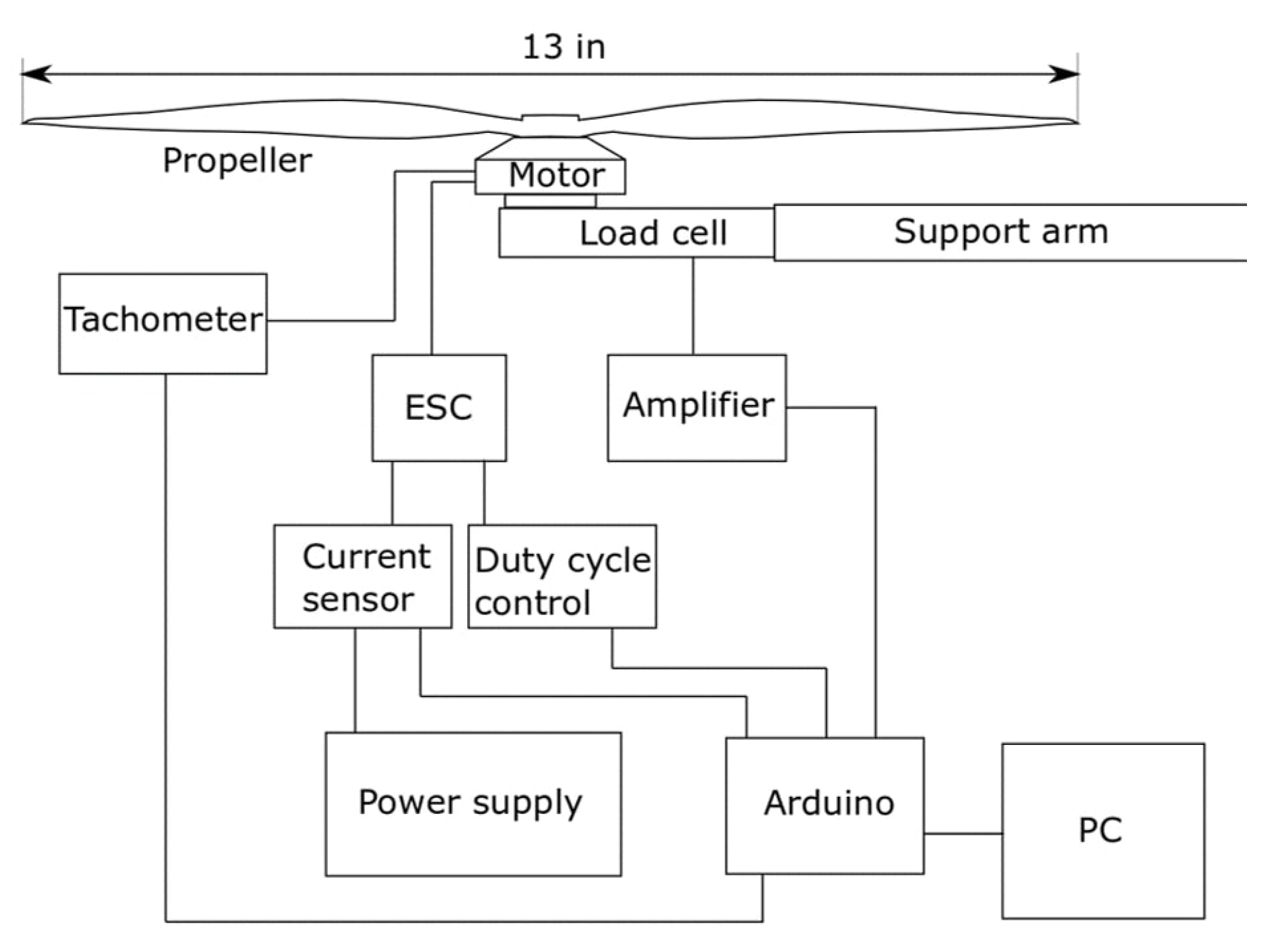
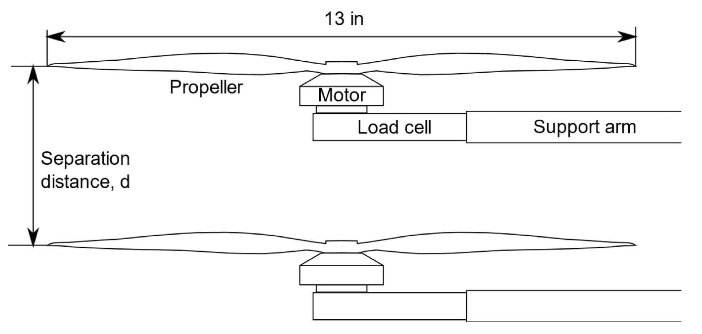
2.1. Experimental Test-Bed

The test bed consists of motors, propellers, load cells, support rods, Data Acquisition (DAQ) system, Electronic Speed Controllers (ESC), DC power supply, and a tachometer, as shown in Figure 2. A motor, along with its propeller, is mounted onto a load cell suspended at the end of a cylindrical support rod, which extends one foot off of a sturdy table to which it is bolted. A power supply provides steady DC power to the motor through a current sensor and an ESC. A servo tester produces a Pulse-Width Modulated (PWM) signal and is used to regulate the duty cycle of the motor through the ESC. Measurements of thrust output and current draw by the motors is recorded using a data acquisition system (DAQ), which includes an Arduino Uno R3. Strain gauge-based load cells with HX711 load cell amplifiers, ACS712 current sensors, and servo testers used are properly calibrated before each set of experiments and feed data to a PC through the Arduino serial connection. The motor speeds are measured using a hand-held DT-2234C+ digital laser tachometer. A coaxial rotor experimental setup is built by mounting each motor and propeller setup, as shown in Figure 3, on two to four adjacent support rods separated by a distance d = 4 inches. This setup enables the testing of multiple coaxial motor-propeller systems separated axially by very small distances.
A 380Kv BLDC motor (T-Motor MN4006-23) rated for use with a six-cell battery and a 13-inch diameter propeller is selected for the tests. “Kv” refers to the RPM at which a motor rotates for each volt applied to it under no-load conditions. Eight of these motors are individually tested, and four of them with the most consistent results are used. The maximum thrust deviation among all the motors tested is found to be only 2%. The motors are powered using the DC power supply at 24.0 volts. The motors are matched with the manufacturer-recommended 13 diameter propellers, and the diameter is kept constant for all experiments. A 4.4 pitch propeller is selected for all experiments, unless otherwise specified. The 4.4 pitch propellers are made of carbon fiber, and others are from “APC” and made from glass fiber composites. The propeller pitch values of the selected APC propellers range from 4 inches to 10 inches, and their designs are consistent with an Eppler E63 airfoil blend with a Clark-Y airfoil. All the propellers are properly balanced, and their properties are given in Table 1, where factor k is the constant thrust to torque ratio of that propeller.
Figure 4a shows the observed rotor speed values for the selected motor and a 13 × 4.4 propeller at different duty cycle values. To validate the developed experimental setup, thrust and power measurements are recorded and compared to published values. As shown in Figure 4b, the measurements taken for an isolated rotor, match closely with those recorded by Ostar-Exel [41] and also those reported in the manufacturer’s datasheet at 22.4 volts at 24.0 volts, respectively, for the same motor and propeller.

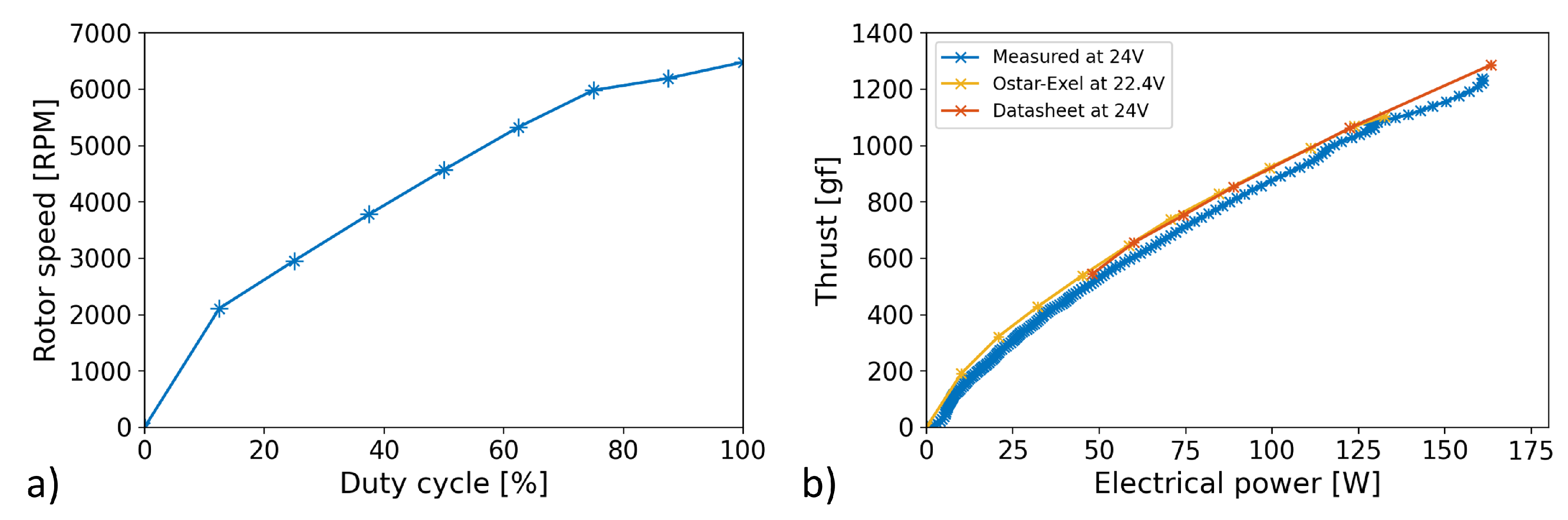
2.2. Accuracy of Measurements

Thrust output, measured in gram-force, and thrust performance, measured as gram-force of thrust output per unit power consumed in watts, are used as metrics [19,34,35]. These metrics are in line with metrics utilized during UAV design [42] and for direct comparison with vehicle weight and payloads [42]. Uncertainties in thrust and thrust performance measurements are calculated based on the maximum thrust and current conditions. The uncertainty is calculated according to the equipment specifications for the load cell and amplifier, the full scale uncertainty, calibration scale resolution, noise, temperature drift, and offset drift. They compound to a total bias of ±22.5 gram-force in the maximum thrust measurement, constituting a 2.04% error on the measurement. Uncertainty of the current sensor module is 0.458A and aggregates calibration ammeter accuracy and resolution, sensor noise, and full-scale uncertainty. This error calculated for a motor operating at maximum current draw constitutes 4.60% of the measurement. Thrust performance uncertainty is calculated using the differential approach of calculating propagated error on the equation for performance and evaluated using maximum thrust and current values as done above. The uncertainty is 0.232 g/W, which is 4.81% of the performance of a motor operating as mentioned.

3. Results and Discussion

Typical thrust output and performance results at different duty cycle values and propeller pitch values of independent rotors as well as complete systems of two to four coaxial rotors are discussed in this section.

3.1. Two-Rotor Coaxial System

The duty cycles of the front and back motors in a two-rotor coaxial system setup are varied to compare the thrust output and performance of individual rotors to that of the combined system. Propellers of 13-inch diameter and with a pitch of 4.4 inches are utilized.

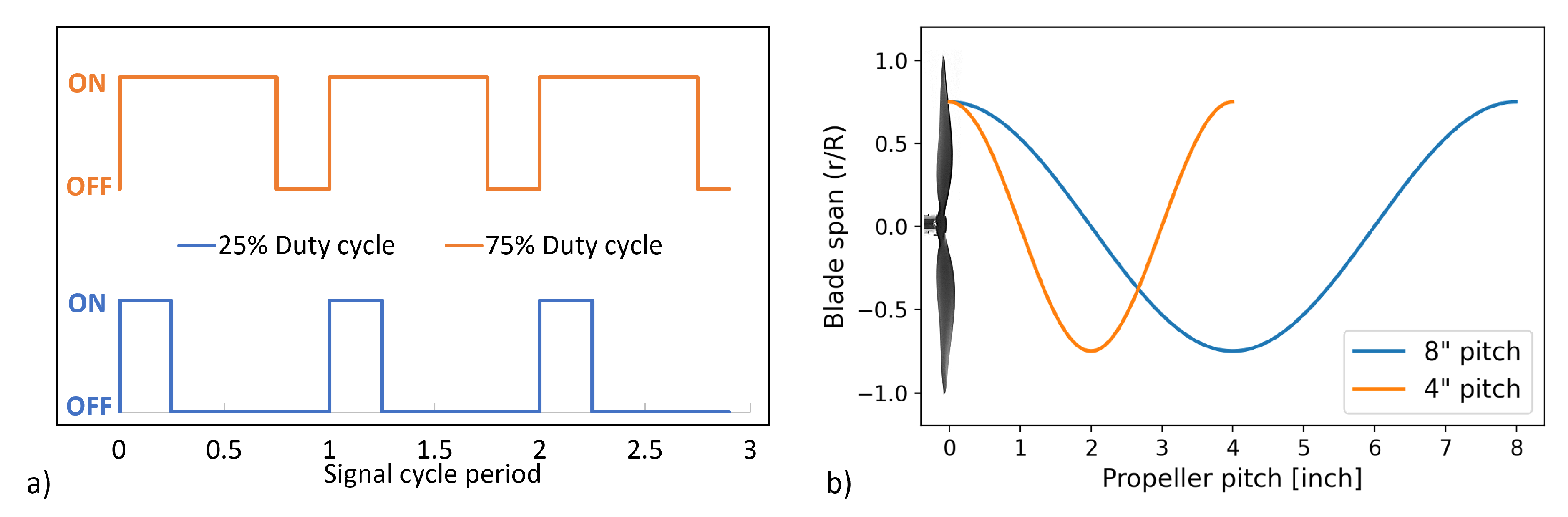
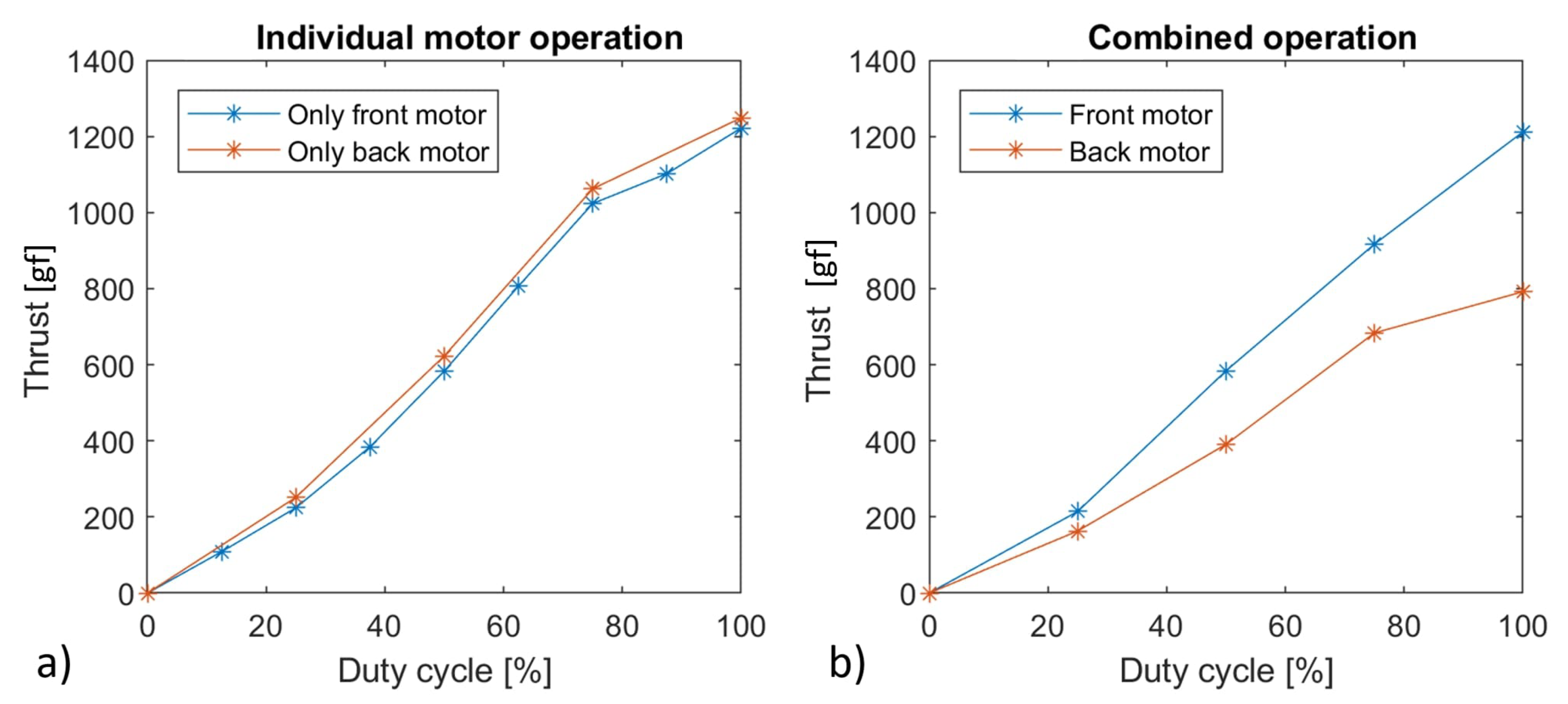
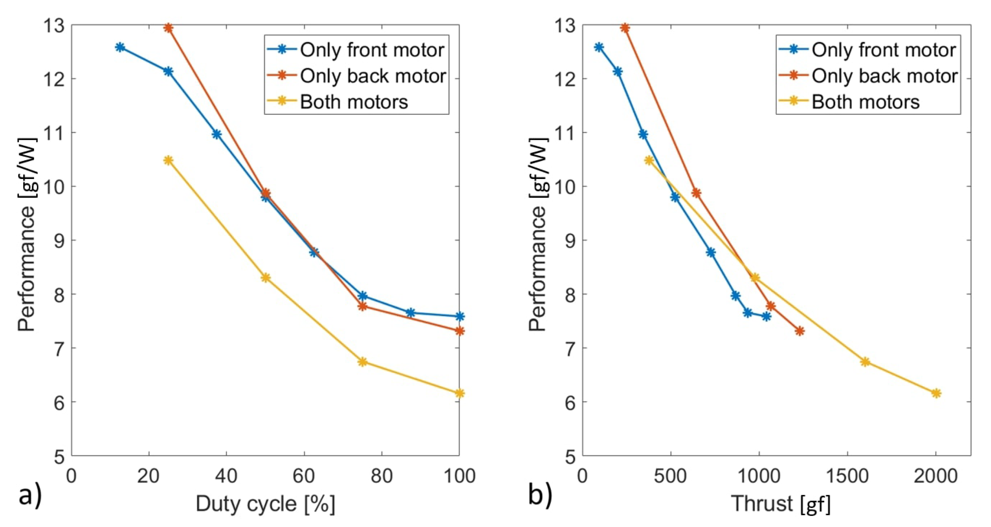
3.1.1. Duty Cycle Effects on the Individual Rotors in a Two-Rotor Coaxial Setup

The front and back rotors are each independently operated while the other rotor is turned off to measure the thrust generated in gram-force by the individual rotors. The duty cycle is incremented in steps from 0 to 100%, while thrust output and current-draw by the motor are measured. The front rotor thrust for the front rotor only operation and vice-versa for the back rotor are indicated in Figure 5a. It shows that the thrust generated by the front and back rotor, in a coaxial configuration, during independent operation are very similar and match closely with that of an isolated motor-propeller system. When the duty cycle of both rotors is incremented simultaneously, the thrust output from each rotor is indicated in Figure 5b, to compare to the individual rotor operation observed in Figure 5a. It shows that the front rotor’s thrust output does not change while that of the back rotor is consistently lower at all duty cycles and loses about 36% thrust when compared to independent operation at 100% duty cycle. This agrees with results from the reviewed literature that, for a coaxial setup, the back rotor is affected adversely due to the operation of the front rotor. This is due to the drag force caused on the back rotor due to the backwash from the front rotor. Overall, a 21%, 19%, 23% and 19% loss in total system thrust is observed at 25%, 50%, 75% and 100% duty cycles, respectively. This is calculated by comparing the sum of the thrusts during combined operation shown in Figure 5b compared to the sum of the thrusts during the individual rotor operations shown in Figure 5a. As a result, using a two-rotor coaxial system results in about 20% loss in system thrust compared to two isolated rotors.
The results from Figure 5a,b show that the coaxial rotor configuration causes the back rotor to be adversely affected more than the front rotor. To more closely understand and observe these effects, the front rotor is operated at a fixed duty cycle (0, 25, 50, 75, or 100%), while the back rotor’s duty cycle is incremented in steps from 0 to 100% as shown in Figure 6a. This shows that front rotor’s thrust at any fixed duty cycle remains relatively constant, while back rotor’s duty cycle is varied. When the same is tested for the back rotor, as shown in Figure 6b, the back rotor’s thrust gradually decreases while the front rotor’s duty cycle is increased from 0 to 100%. The thrust reduction is significant, and for example, while the back rotor is operated at 75% duty cycle, a thrust drop of 507 gram-force is experienced by it. When the back rotor is turned off, i.e., at 0% duty cycle, the backwash caused by the rotating front rotor induces a drag force of 180 gram-force on the back rotor, viewed as negative thrust in Figure 6b. The front rotor’s backwash also causes the back rotor to have a non-zero inlet free stream velocity while that of the front rotor is 0 m/s. The two plots corroborate our previous finding that the back rotor is affected more adversely than the front rotor in the coaxial setup.
A key indicator for the effectiveness and efficiency of motor-propeller systems is thrust performance, which is defined as the thrust generated by a rotor for each unit of consumed power and measured in gram-force of thrust per watt. Thrust performance is calculated by measuring a propeller’s thrust output and its motor’s power consumption. The effect of coaxial setup and variation of the back rotor’s duty cycle on the front rotor’s thrust performance is shown in Figure 7a. It shows that the front rotor’s performance at very low duty cycles (around 25%) reduces by about 17% as the back rotor duty cycle is increased from 0 to 100%. Moreover, the front rotor performance at higher duty cycles (25% to 100%) is not affected by the back rotor’s operation and remains unchanged. A similar figure for the back rotor shown in Figure 7b shows that the back rotor’s performance is significantly affected by front rotor operation. It is observed that, as the back motor duty cycle is lowered, the adverse effect on its thrust performance due to the front rotor increases. At 25% back motor duty cycle and high front rotor duty cycles (>60%), the front rotor’s backwash causes the back rotor to have a net negative thrust output and consequently a negative thrust performance value. Overall, higher performance is achieved for a rotor at a lower duty cycle while the other rotor is turned off, and this is also true for isolated rotors. Additionally, negative values of thrust and thrust performance are experienced by the back rotor at lower back motor duty cycles and high front motor duty cycles, which should be avoided.

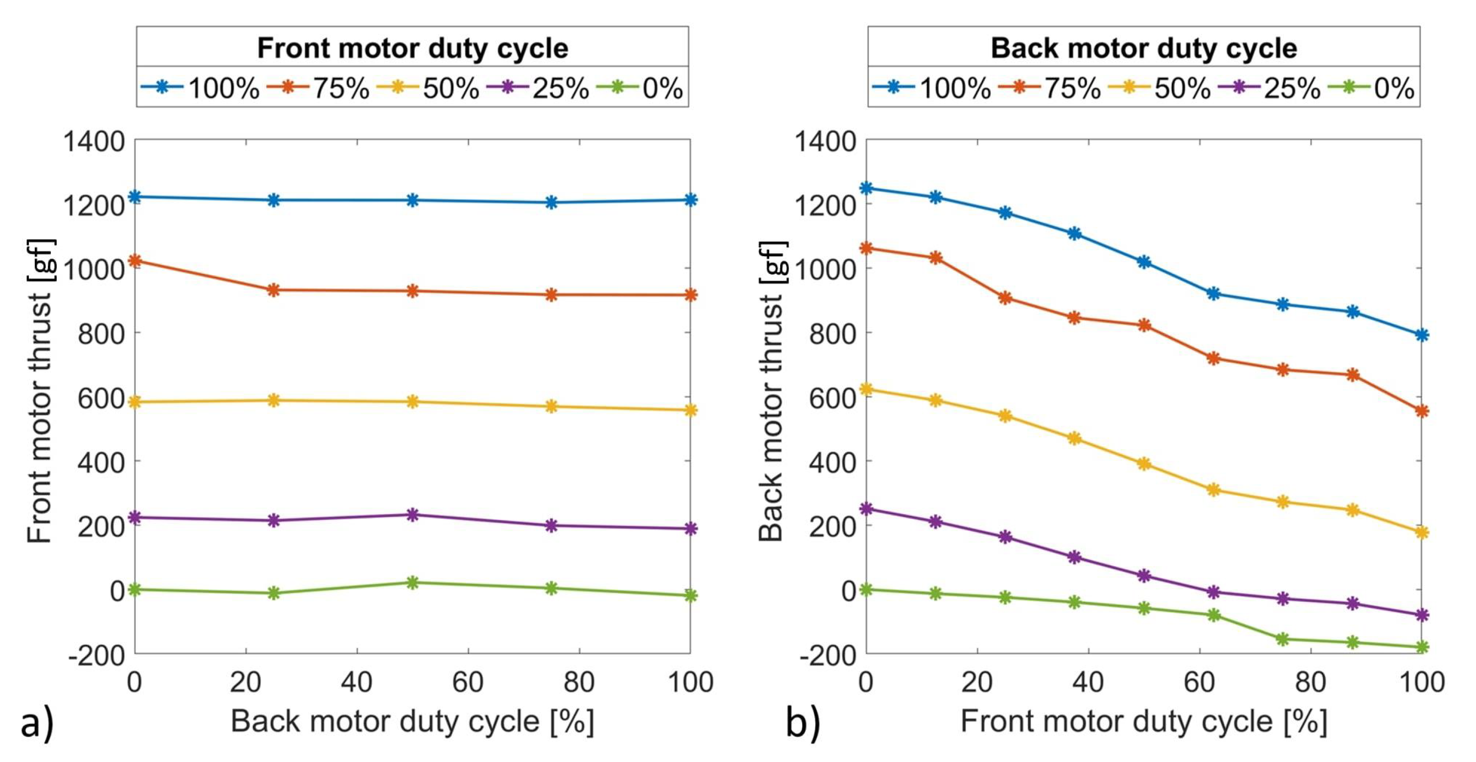
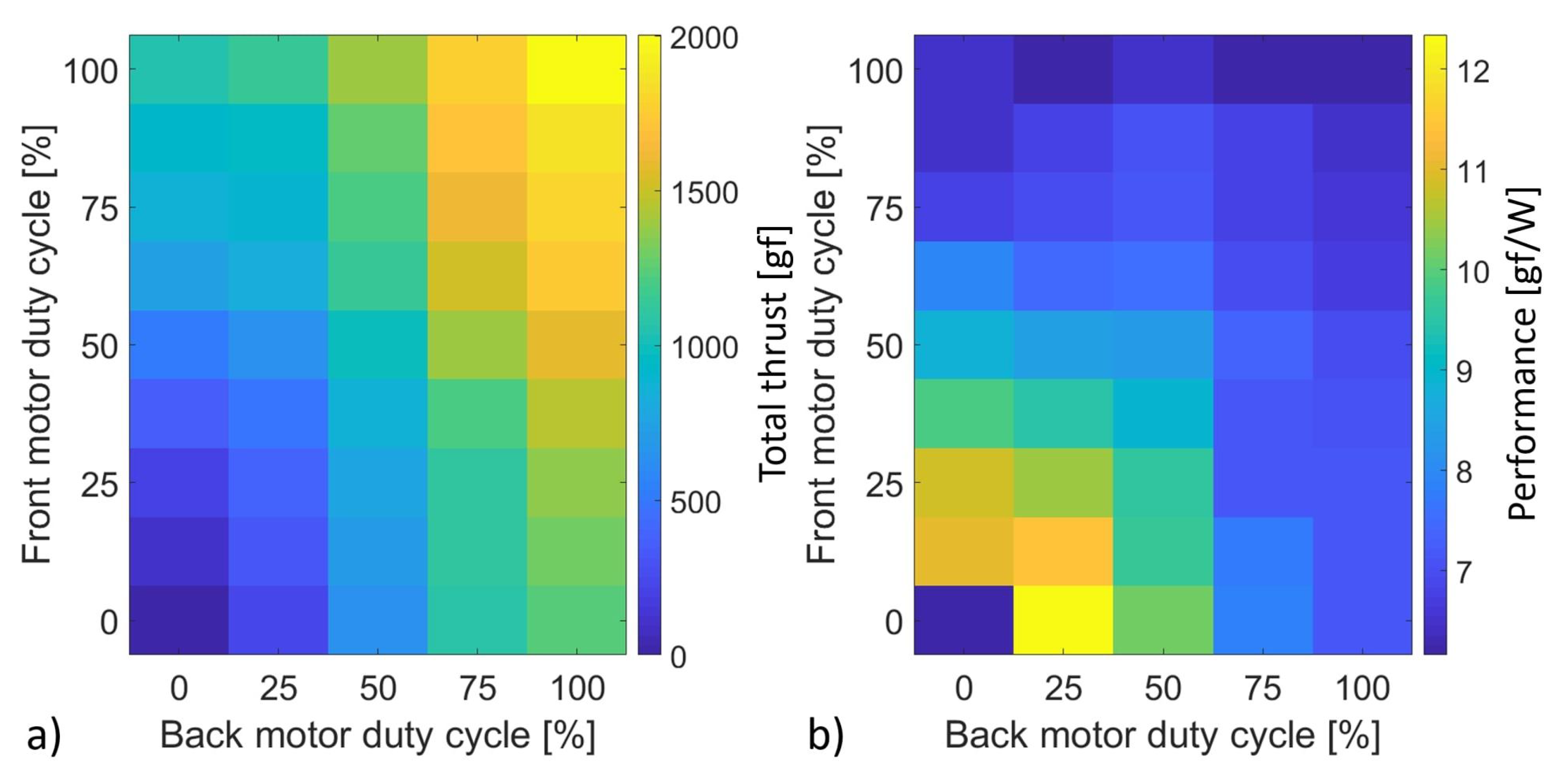
3.1.2. Duty Cycle Effects on the Combined System in a Two-Rotor Coaxial Setup

A system-level analysis beyond the individual rotor results is performed to evaluate the net useful effect of the two-rotor coaxial propulsion system. The thrust outputs from the two rotors and total power consumption are measured to calculate net useful thrust and thrust performance at varying duty cycles. The system performance is plotted for several fixed back motor duty cycles while the front rotor duty cycle is incremented as shown in Figure 8a. The figure indicates that in general, when either front or back motor duty cycle is increased, the system performance values drop significantly. When the front motor duty cycle is increased, the drop in system performance is higher for lower back motor duty cycles than that for higher back motor duty cycles. System performance reduces to about six g/W when the front motor duty cycle is increased to 100% duty cycle irrespective of the back motor duty cycle. System performance values are plotted against the total thrust output for multiple back rotor duty cycles to determine the maximum performance possible for a given thrust requirement and the duty cycle combination capable of achieving such a result. As shown in Figure 8b, it can be observed that a particular total thrust output can be obtained at several back motor duty cycles. The plot also shows that, for a specific thrust output requirement, higher system performance is achieved by using a duty cycle combination with a higher back rotor duty cycle and its corresponding front motor duty cycle.
The performance benefit of utilizing the back rotor’s thrust first instead of the front rotor is more clearly indicated through Figure 9a,b. These figures show system performance variation for three cases: when only the front rotor is operated, when only the back rotor is operated, and when both rotors are operated simultaneously at the same duty cycle. Figure 9a shows that operating only one rotor results in similar thrust-performance versus duty cycle behavior irrespective of the rotor location in a coaxial setup. However, when both rotors are operated together, incrementing their duty cycles simultaneously, the system thrust performance is significantly lower compared to that of individual rotor operation. From Figure 9b, it can be observed that the combined operation generates a maximum of about 2000 gram-force of thrust compared to about 1200 gram-force of thrust for the back rotor only operation. Moreover, it is evident from the figure that the system performance is nearly 10% higher for the back rotor only operation compared to the front rotor only operation for the same thrust outputs. Moreover, the maximum system thrust output is 18% higher for the back rotor operation than that generated by the front rotor. The lower system thrust and performance observed during front rotor only operation is due to the negative thrust induced by the front rotor’s backwash on the back rotor even when the back motor is turned off. Analyzing Figure 9a,b together shows that the front rotor only operation produces lower system thrust values than the back rotor only operation for the same duty cycle inputs. This is the reason for the “only back motor” line in Figure 9b to be shifted to the right compared to the “only front motor” line.
As a system, the back rotor generates thrust at a superior thrust performance than the front rotor when the other rotor is turned off. Hence when the thrust requirement is low, the back rotor only operation should be preferred for lower power consumption. From Figure 9b, it may also be concluded that, for much higher system thrust requirements (1000 to 1200 gram-force), instead of operating only the back rotor at very high duty cycles, a higher thrust performance can be achieved by operating both rotors together at a corresponding duty cycle, which is lower. This is because the thrust performance of a motor-propeller system is higher at lower duty cycles, as shown in Figure 9a. It is observed that the performance benefit of having both rotors operate at a lower duty cycle is larger than the negative effect of the front rotor’s backwash on the back rotor.
Front and back motor duty cycles are varied independently to determine the best duty cycle combination to achieve a required system thrust output with the maximum possible system thrust performance. System thrust and performance heat maps are generated and shown in Figure 10. Figure 10a indicates that when the duty cycles on either motor is increased from 0% located at the left or bottom edge of the map to 100% located at the top or right edge of the map, system thrust output increases monotonously. In addition, Figure 10b shows that the higher performance is achieved at lower duty cycles where, unfortunately, lower thrust is generated and, for higher thrust outputs, higher duty cycles are required where poor system performance is observed. In view of this negative correlation between thrust and performance, a duty cycle path needs to be chosen to increase thrust output from the 0% duty cycle (zero thrust) corner to the 100% duty cycle (maximum thrust) corner. This path increments either front or back motor duty cycle individually to increase thrust output such that the least possible performance is compromised as a result in each step. Using the system thrust and system performance maps shown in Figure 10a,b, the optimal path includes first increasing the back motor duty cycle to almost 75% and then incrementing the front motor duty cycle from 0% to about 75%. If additional thrust is required, the back motor duty cycle is to be maximized to 100% before increasing the front motor duty cycle to 100%. This path results in retaining the maximum possible system performance for any required total thrust output.

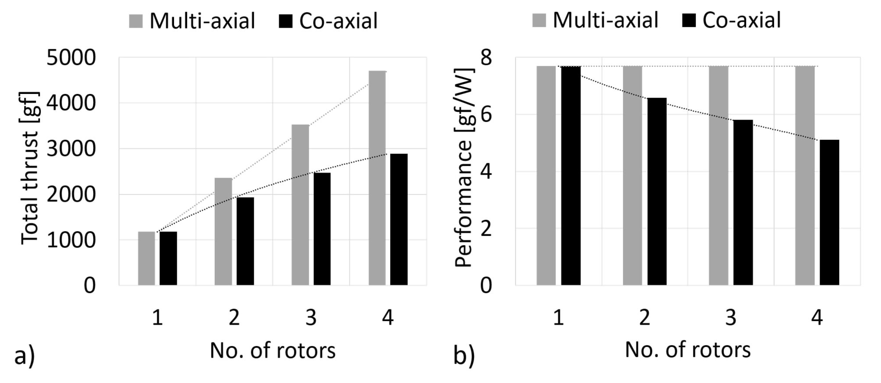
3.2. Additional Coaxial Rotors

The effect of adding a third and a fourth rotor to the two-rotor coaxial system on system thrust output, performance, and thrust sharing among rotors is analyzed in this section. The effects of pitch variations in a four-rotor coaxial system are also investigated.

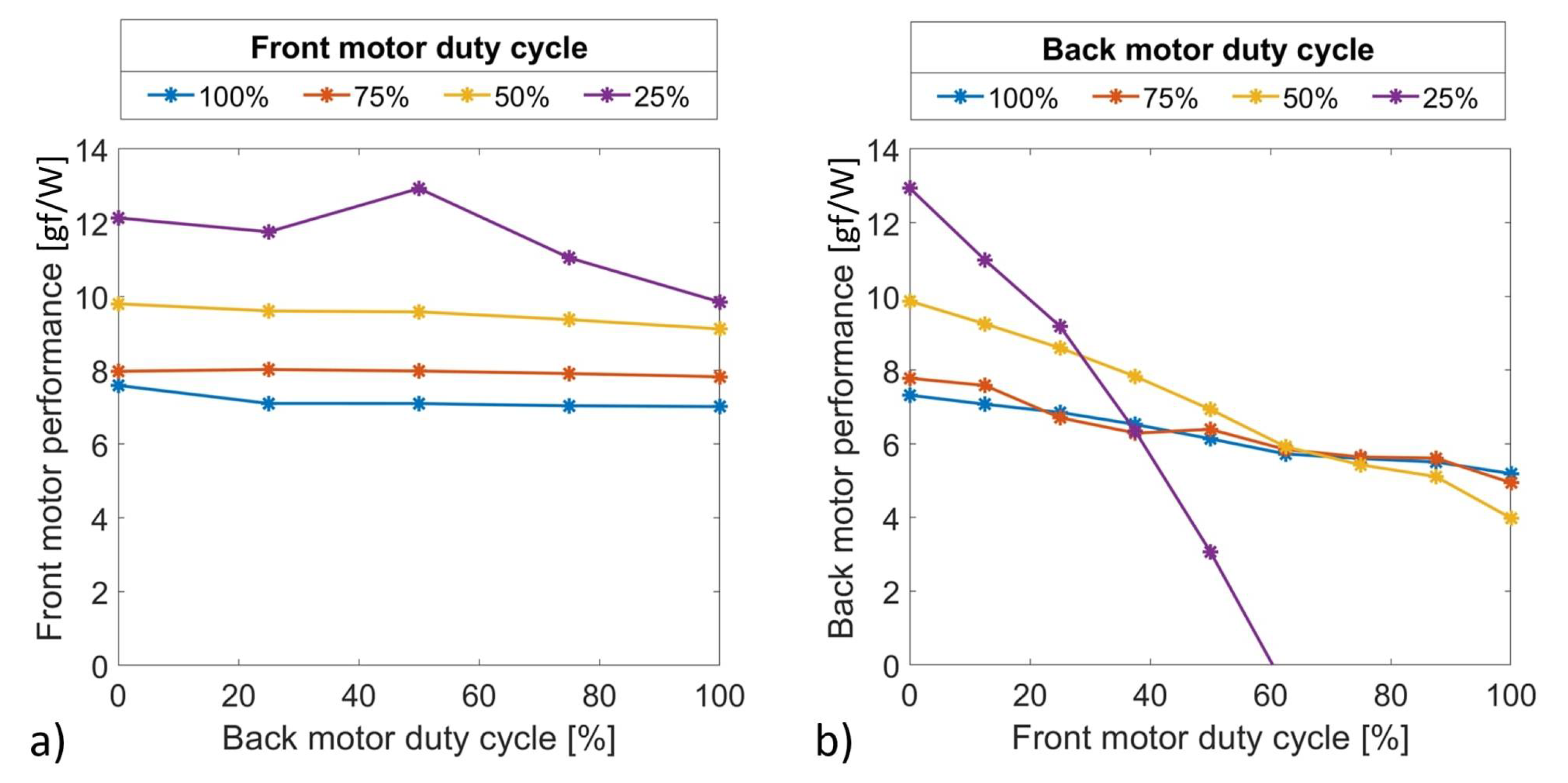
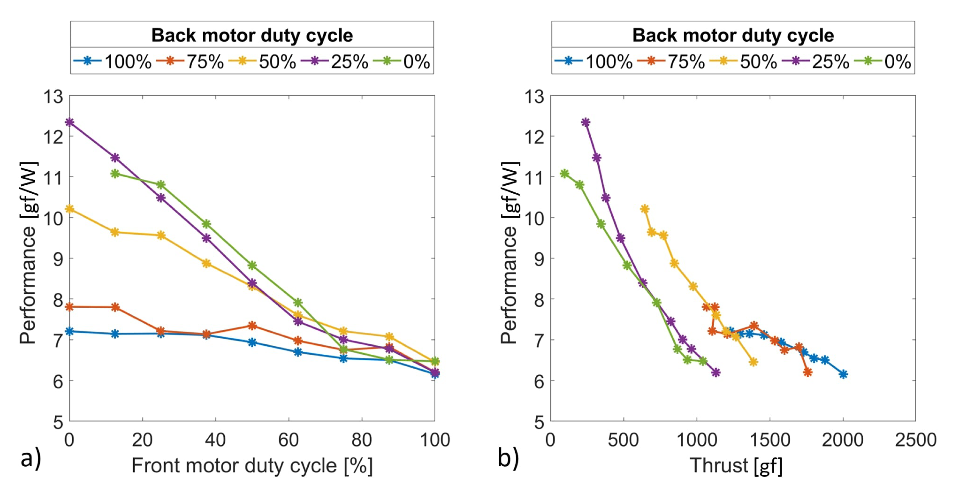
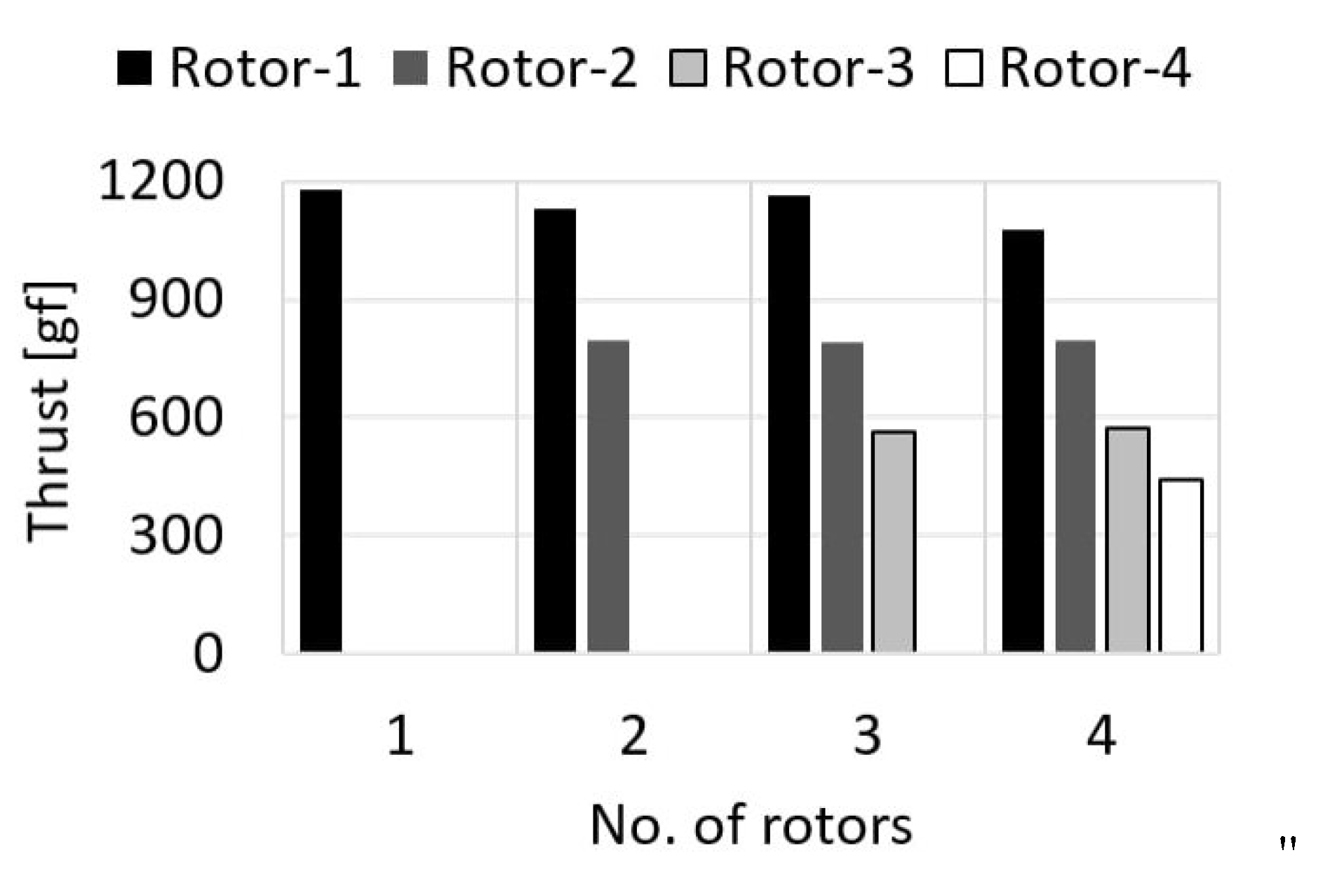
3.2.1. Thrust and Performance Variations

The increase in the total thrust of a coaxial system with each additional rotor in comparison to a multi-axial system (up to four rotors) is indicated in Figure 11a. Each motor is supplied with equal power input, and the total thrust output of the four rotors is plotted in the figure. The total thrust output with 2, 3, and 4 rotors is 1.6, 2.1, and 2.5 times that of a single rotor, respectively. Total thrust is lower by about 3% when all four propellers rotated in the same direction. The system performance is plotted in Figure 11b and shows a gradual reduction of thrust performance in comparison to an isolated rotor with values of 85.5%, 75.5%, and 66.4% for 2, 3, and 4 coaxial rotor systems, respectively. It can be observed from the two plots that each additional coaxial rotor increases the total thrust by a fraction of the thrust of the immediately upstream rotor. This increment in thrust is accompanied by a decrease in the system performance.
Thrust sharing among the rotors in the 2–4 rotor coaxial systems is shown in Figure 12 to determine the thrust loading and the fraction of the total thrust produced by each rotor. It shows that an upstream rotor’s thrust is always greater than that of any of its downstream rotors. This relation holds true even for two- and three-rotor coaxial systems. For the coaxial setup with four rotors, the thrust output of each rotor from the first to the fourth rotor is 91%, 68%, 49%, and 37% of that of an individual rotor, respectively. This indicates that a coaxial system with the same pitch value on all propellers results in an uneven thrust sharing between motors, with the largest portion of total thrust being generated by the frontmost rotor and the smallest fraction produced by the rearmost rotor.

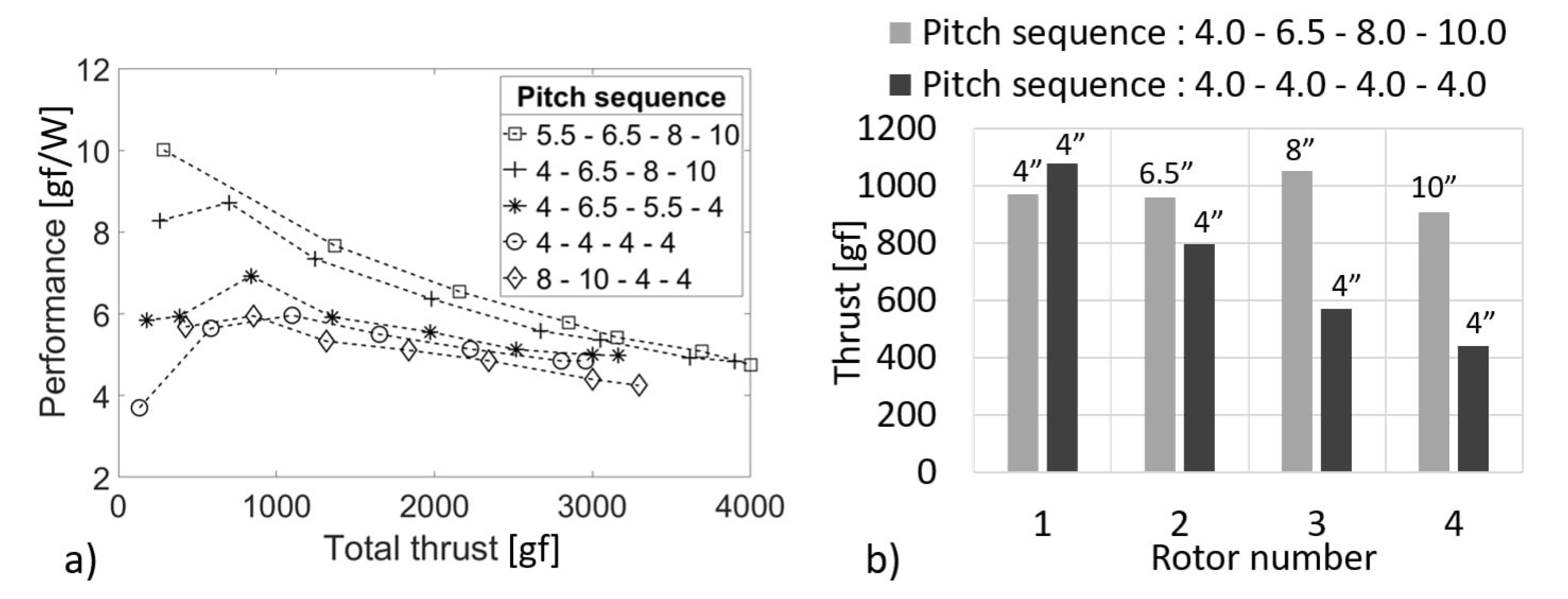
3.2.2. Pitch Variation in a Four-Rotor Coaxial System

Several propeller pitch combinations are tested on the four-rotor coaxial setup to observe the effects on system thrust and performance and to determine the best pitch combination. Out of the five pitch combinations tested, the highest performance is observed when the propeller pitch values are incremented from the first rotor to the last rotor. Moreover, the lowest performance is observed when the propeller pitch values are decremented from the first to the last rotor. Results are shown in Figure 13a, where system performance for five different pitch combinations is plotted against total thrust output while the duty cycle signal on all four motors is simultaneously increased from 12.5% to 100%. The lowest system performance at almost all duty cycles is observed for the propeller pitch combination of 8 , 10 , 4 and 4 from the first propeller to the fourth propeller. In this pitch combination, the first two propellers have very large pitch values of 8 and 10 while compared to 4 pitch on the third and fourth propellers. The top two best system performances at all duty cycles are observed for the pitch combinations of 5.5 , 6.5 , 8 , and 10 and 4 , 6.5 , 8 , and 10 . Both pitch combinations follow the same pattern wherein the propeller pitch values increment gradually from the first propeller to the fourth propeller. The 5.5 , 6.5 , 8 and 10 pitch combination has a slightly higher maximum total thrust at 100% duty cycle than the 4 , 6.5 , 8 and 10 pitch combination. Moreover, it also has a slightly higher performance, since its front most 5 pitch propeller can generate same thrust as the 4 pitch propeller at a lower duty cycle corresponding to a higher performance value. Figure 13b, shows the distribution of the total system thrust among the four rotors in the coaxial setup for two cases. The coaxial system with all 4 pitch propellers is compared to a system with a 4 , 6.5 , 8 , and 10 propeller pitch combination. For the latter pitch combination with sequentially increasing pitch values, the second, third, and fourth rotors generated about 99%, 108%, and 93%, respectively, compared to that of the first rotor. The tests indicate that similar to the two-rotor coaxial systems [35], better performance is achieved when propeller pitch values increase incrementally from the first to the last propeller. This also helps to achieve uniform thrust distribution among all the rotors in a coaxial system.

4. Conclusions

Experimental analysis of coaxial rotors with two to four rotors is conducted to determine optimal configurations and operational strategies for improved performance. Specifically, motor duty cycle and propeller pitch parameters were varied to compare different design configurations and operational strategies. Experiments are conducted using 13-inch diameter propellers of different pitch values and a contra-rotating coaxial setup, known to have better performance. Thrust output and thrust performance measured in gram-force per watt of individual rotors and combined systems are used to compare the results from different experiments. Experiments corroborated previously published works on coaxial rotors where the back rotor performance is adversely affected by the front rotor’s backwash. They also demonstrated that adopting a coaxial two-rotor configuration, which cuts down its area footprint by 50%, instead of a two-rotor multi-axis system, reduces the system thrust output by only 20%.
In order to operate a two-rotor coaxial system always at maximum thrust performance, only the back motor should be utilized initially up to 75% duty cycle before increasing the front motor’s duty cycle up to 75%. Additional thrust requirements should be met by the back motor and then by the front motor up to their maximum output. Coaxial rotor systems with two, three, and four-rotors generated 1.6, 2.1, and 2.5 times the thrust output at system performance of 86%, 76%, and 66%, respectively, of that of an isolated rotor. Moreover, thrust sharing among rotors is not uniform and decreases for all downstream propellers for the same power input to all motors. Co-rotating four-rotor coaxial system generated about 3% lower total thrust output than with a contra-rotating setup. An almost uniform thrust sharing among rotors in a four-rotor coaxial system can be achieved by gradually increasing propeller pitch values from the first to the last rotor. From among the tested propeller combinations, this was achieved with a pitch combination of 4 , 6.5 , 8 and 10 for the first, second, third, and fourth rotors, respectively. The system performance of such an increasing pitch four-rotor coaxial system is also higher in contrast to rotor setups with constant or decreasing pitch values. Utilizing these results to design and operate eVTOL vehicles is expected to reduce power utilization and extend vehicle endurance and range.

Author Contributions

Conceptualization, J.E.H. and M.M.M.; methodology, J.E.H. and J.P.R.; software, J.E.H. and J.P.R.; validation, J.E.H. and J.P.R.; formal analysis, J.E.H. and J.P.R.; investigation, J.E.H. and J.P.R.; resources, J.F.D.; data curation, J.E.H. and J.P.R.; writing—original draft preparation, J.P.R. and J.E.H.; writing—review and editing, J.P.R., M.M.M. and J.F.D.; visualization, J.P.R. and J.E.H.; supervision, J.F.D.; project administration, J.F.D.; funding acquisition, J.F.D. All authors have read and agreed to the published version of the manuscript.

Funding

This research was partially supported by Office of Naval Research (ONR), Grant No. N00014-15-2235 with Dr. Thomas McKenna serving as Program Manager and also partially supported by a subcontract with SubUAS LLC a small business concern with a ONR contract number N00014-16-P-3043 with Mr. Brian Almquist serving as Program Manager.

Institutional Review Board Statement

Not applicable.

Informed Consent Statement

Not applicable.

Data Availability Statement

Data are contained within the article.

Conflicts of Interest

The authors declare no conflict of interest.

Abbreviations

The following abbreviations are used in this manuscript:
BLDCBrush-Less Direct Current
DCDirect Current
eVTOLElectric Vertical Take-Off and Landing
UAVUnmanned Aerial Vehicle
PWMPulse Width Modulation
DAQData Acquisition
RPMRotation Per Minute

References

  1. Leishman, J.G. The Bréguet-Richet Quad-Rotor Helicopter of 1907. Vertiflite 2001, 47, 58–60. [Google Scholar]
  2. Wang, Q. The Current Research Status and Prospect of Multi-rotor UAV. IOSR J. Mech. Civ. Eng. 2017, 14, 31–35. [Google Scholar] [CrossRef]
  3. Puttock, A.; Cunliffe, A.; Anderson, K.; Brazier, R.E. Aerial photography collected with a multirotor drone reveals impact of Eurasian beaver reintroduction on ecosystem structure. J. Unmanned Veh. Syst. 2015, 3, 123–130. [Google Scholar] [CrossRef]
  4. Bemis, S.P.; Micklethwaite, S.; Turner, D.; James, M.R.; Akciz, S.; Thiele, S.T.; Bangash, H.A. Ground-based and UAV-based photogrammetry: A multi-scale, high-resolution mapping tool for structural geology and paleoseismology. J. Struct. Geol. 2014, 69, 163–178. [Google Scholar] [CrossRef]
  5. Velusamy, P.; Rajendran, S.; Mahendran, R.K.; Naseer, S.; Shafiq, M.; Choi, J.G. Unmanned Aerial Vehicles (UAV) in precision agriculture: Applications and challenges. Energies 2021, 15, 217. [Google Scholar] [CrossRef]
  6. Barmpounakis, E.N.; Vlahogianni, E.I.; Golias, J.C. Unmanned Aerial Aircraft Systems for transportation engineering: Current practice and future challenges. Int. J. Transp. Sci. Technol. 2016, 5, 111–122. [Google Scholar] [CrossRef]
  7. Yeong, S.; King, L.; Dol, S. A Review on Marine Search and Rescue Operations Using Unmanned Aerial Vehicles. Int. J. Mech. Aerosp. Ind. Mechatron. Manuf. Eng. 2015, 9, 396–399. [Google Scholar] [CrossRef]
  8. Ollero, A.; Merino, L. Unmanned aerial vehicles as tools for forest-fire fighting. For. Ecol. Manag. 2006, 234, 263–274. [Google Scholar] [CrossRef]
  9. Thiels, C.A.; Aho, J.M.; Zietlow, S.P.; Jenkins, D.H. Use of Unmanned Aerial Vehicles for Medical Product Transport. Air Med J. 2015, 34, 104–108. [Google Scholar] [CrossRef]
  10. Li, Y.; Liu, C. Applications of multirotor drone technologies in construction management. Int. J. Constr. Manag. 2019, 19, 401–412. [Google Scholar] [CrossRef]
  11. Seo, J.; Duque, L.; Wacker, J. Drone-enabled bridge inspection methodology and application. Autom. Constr. 2018, 94, 112–126. [Google Scholar] [CrossRef]
  12. Elmeseiry, N.; Alshaer, N.; Ismail, T. A detailed survey and future directions of unmanned aerial vehicles (uavs) with potential applications. Aerospace 2021, 8, 363. [Google Scholar] [CrossRef]
  13. Vas, E.; Lescroël, A.; Duriez, O.; Boguszewski, G.; Grémillet, D. Approaching birds with drones: First experiments and ethical guidelines. Biol. Lett. 2015, 11, 20140754. [Google Scholar] [CrossRef] [PubMed]
  14. Johnson, W.; Silva, C. NASA concept vehicles and the engineering of advanced air mobility aircraft. Aeronaut. J. 2022, 126, 59–91. [Google Scholar] [CrossRef]
  15. Maia, M.M.; Soni, P.; Diez, F.J. Demonstration of an aerial and submersible vehicle capable of flight and underwater navigation with seamless air-water transition. arXiv 2015, arXiv:1507.01932. [Google Scholar]
  16. Villegas, A.; Mishkevich, V.; Gulak, Y.; Diez, F.J. Analysis of key elements to evaluate the performance of a multirotor unmanned aerial–aquatic vehicle. Aerosp. Sci. Technol. 2017, 70, 412–418. [Google Scholar] [CrossRef]
  17. Ramasamy, M. Hover Performance Measurements Toward Understanding Aerodynamic Interference in Coaxial, Tandem, and Tilt Rotors. J. Am. Helicopter Soc. 2015, 60, 1–17. [Google Scholar] [CrossRef]
  18. Ravell, D.A.M.; Maia, M.M.; Diez, F.J. Modeling and Control of Unmanned Aerial/Underwater Vehicles using Hybrid Control. Control Eng. Pract. 2018, 76, 112–122. [Google Scholar] [CrossRef]
  19. Bondyra, A.; Gardecki, S.; Gasior, P.; Giernacki, W. Performance of Coaxial Propulsion in Design of Multi-rotor UAVs. In Proceedings of the Challenges in Automation, Robotics and Measurement Techniques, Warsaw, Poland, 2–4 March 2016; pp. 523–531. [Google Scholar] [CrossRef]
  20. Harrington, R.D. Full-Scale-Tunnel Investigation of the Static-Thrust Performance of a Coaxial Helicopter Rotor; Technical Note NACA-TN-2318; National Advisory Committee for Aeronautics, Langley Aeronautical Lab: Langley Field, VA, USA, 1951. [Google Scholar]
  21. Coleman, C.P. A Survey of Theoretical and Experimental Coaxial Rotor Aerodynamic Research; Technical Report NASA-TP-3675; NASA Ames Research Center: Moffett Field, CA, USA, 1997.
  22. Taylor, M.K. A Balsa-Dust Technique for Air-Flow Visualization and Its Application to Flow through Model Helicopter Rotors in Static Thrust; Technical Note NACA-TN-2220; National Advisory Committee for Aeronautics, Langley Aeronautical Lab: Langley Field, VA, USA, 1950. [Google Scholar]
  23. McAlister, K.; Tung, C.; Rand, O.; Khromov, V.; Wilson, J. Experimental and numerical study of a model coaxial rotor. In Proceedings of the American Helicopter Society 62nd Annual Forum, Phoenix, AZ, USA, 9–11 May 2006. [Google Scholar]
  24. Jinghui, D.; Feng, F.; Huang, S.; Lin, Y. Aerodynamic characteristics of rigid coaxial rotor by wind tunnel test and numerical calculation. Chin. J. Aeronaut. 2019, 32, 568–576. [Google Scholar] [CrossRef]
  25. Lim, J.W.; McAlister, K.W.; Johnson, W. Hover Performance Correlation for Full-Scale and Model-Scale Coaxial Rotors. J. Am. Helicopter Soc. 2009, 54, 1–14. [Google Scholar] [CrossRef]
  26. Wang, C.; Huang, M.; Peng, X.; Zhang, G.; Tang, M.; Wang, H. Wind Tunnel Studies on Hover and Forward Flight Performances of a Coaxial Rigid Rotor. Aerospace 2021, 8, 205. [Google Scholar] [CrossRef]
  27. Zimmer, H. The Aerodynamic Calculation of Counter Rotating Coaxial Rotors. In Proceedings of the Eleventh European Rotorcraft Forum, London, UK, 10–13 September 1985. [Google Scholar]
  28. Leishman, J.G.; Ananthan, S. An Optimum Coaxial Rotor System for Axial Flight. J. Am. Helicopter Soc. 2008, 53, 366–381. [Google Scholar] [CrossRef]
  29. Xu, H.; Ye, Z. Numerical Simulation of Unsteady Flow Around Forward Flight Helicopter with Coaxial Rotors. Chin. J. Aeronaut. 2011, 24, 1–7. [Google Scholar] [CrossRef]
  30. Bolandi, H.; Rezaei, M.; Mohsenipour, R.; Nemati, H.; Smailzadeh, S.M. Attitude control of a quadrotor with optimized PID controller. Intell. Control. Autom. 2013, 4, 342–349. [Google Scholar] [CrossRef]
  31. Brandt, J.; Selig, M. Propeller Performance Data at Low Reynolds Numbers. In Proceedings of the 49th AIAA Aerospace Sciences Meeting, Orlando, FL, USA, 4–7 January 2011. [Google Scholar] [CrossRef]
  32. Merchant, M.; Miller, L.S. Propeller Performance Measurement for Low Reynolds Number UAV Applications. In Proceedings of the 44th AIAA Aerospace Sciences Meeting, Reno, NV, USA, 9–12 January 2006; AIAA Paper 2006-1127. p. 1127. [Google Scholar] [CrossRef]
  33. Brazinskas, M.; Prior, S.D.; Scanlan, J.P. An Empirical Study of Overlapping Rotor Interference for a Small Unmanned Aircraft Propulsion System. Aerospace 2016, 3, 32. [Google Scholar] [CrossRef]
  34. Buzzatto, J.; Liarokapis, M. A Benchmarking Platform and a Control Allocation Method for Improving the Efficiency of Coaxial Rotor Systems. IEEE Robot. Autom. Lett. 2022, 7, 5302–5309. [Google Scholar] [CrossRef]
  35. Simões, C.M. Optimizing a Coaxial Propulsion System to a Quadcopter; Technical Report; Instituto Superior Técnico: Lisboa, Portugal, 2015. [Google Scholar]
  36. Lakshminarayan, V.K.; Baeder, J.D. Computational Investigation of Microscale Coaxial-Rotor Aerodynamics in Hover. J. Aircr. 2010, 47, 940–955. [Google Scholar] [CrossRef]
  37. Lei, Y.; Bai, Y.; Xu, Z.; Gao, Q.; Zhao, C. An experimental investigation on aerodynamic performance of a coaxial rotor system with different rotor spacing and wind speed. Exp. Therm. Fluid Sci. 2013, 44, 779–785. [Google Scholar] [CrossRef]
  38. Uehara, D.; Sirohi, J.; Bhagwat, M.J. Hover Performance of Corotating and Counterrotating Coaxial Rotors. J. Am. Helicopter Soc. 2020, 65, 1–8. [Google Scholar] [CrossRef]
  39. Lee, Y.B.; Park, J.S. Hover Performance Analyses of Coaxial Co-Rotating Rotors for eVTOL Aircraft. Aerospace 2022, 9, 152. [Google Scholar] [CrossRef]
  40. Biber, K. Determination of propeller pitch stops for a turboprop airplane. In Proceedings of the 38th Aerospace Sciences Meeting and Exhibit, Reno, NV, USA, 10–13 January 2000; p. 497. [Google Scholar] [CrossRef]
  41. Ostar-Exel, L. The Effects of Varying Diameter on Coaxial Propellers for the Propulsion of Multirotor Systems. Ph.D. Thesis, Rutgers University-School of Graduate Studies, Piscataway, NJ, USA, 2019. [Google Scholar] [CrossRef]
  42. Ong, W.; Srigrarom, S.; Hesse, H. Design methodology for heavy-lift unmanned aerial vehicles with coaxial rotors. In Proceedings of the AIAA Scitech 2019 Forum, San Diego, CA, USA, 7–11 January 2019; p. 2095. [Google Scholar] [CrossRef]
Figure 1. (a) 25% and 75% motor duty cycle examples. (b) Forward movement of 4 and 8 pitch propellers for one complete rotation.
Aerospace 09 00452 g001
Figure 2. Line diagram showing the different components of the experimental setup.
Aerospace 09 00452 g002
Figure 3. Schematic of coaxial rotor experimental setup built at Rutgers University, Piscataway, NJ, USA.
Aerospace 09 00452 g003
Figure 4. (a) Rotor speeds at different duty cycle values, and (b) validation of experimental setup by comparing measurements with published results [41].
Aerospace 09 00452 g004
Figure 5. Thrust output from front and back rotors when (a) Front and back rotor are run individually and (b) both rotors are simultaneously operated.
Aerospace 09 00452 g005
Figure 6. (a) Front rotor thrust output while back motor’s duty cycle is incremented. (b) Back rotor thrust output while front motor’s duty cycle is incremented.
Aerospace 09 00452 g006
Figure 7. (a) Front rotor performance for different back motor duty cycles. (b) Back rotor performance values for different front motor duty cycles.
Aerospace 09 00452 g007
Figure 8. System performance values for different back motor duty cycles against (a) Front motor duty cycle and (b) Total thrust output.
Aerospace 09 00452 g008
Figure 9. System performance for individual rotor runs compared to combined operation against (a) duty cycle and (b) total thrust output.
Aerospace 09 00452 g009
Figure 10. (a) System thrust output heat map and (b) System performance heat map for incremental front and back motor duty cycles.
Aerospace 09 00452 g010
Figure 11. (a) Total thrust output and (b) System performance for one to four-rotor coaxial systems compared to multi-axial systems.
Aerospace 09 00452 g011
Figure 12. Thrust distribution among rotors for one to four-rotor coaxial systems.
Aerospace 09 00452 g012
Figure 13. (a) System performance of four-rotor coaxial system for different pitch combinations. (b) Thrust distribution among rotors for sequentially increasing and constant pitch combinations.
Aerospace 09 00452 g013
Table 1. List of propellers tested.
Diameter (in)Pitch (in)MaterialFactor k
134.0Glass fiber7.758
134.4Carbon fiber6.180
135.5Glass fiber6.570
136.5Glass fiber5.959
138.0Glass fiber5.605
1310.0Glass fiber4.608
Publisher’s Note: MDPI stays neutral with regard to jurisdictional claims in published maps and institutional affiliations.

