1. Introduction
After decades of space flight, an increasing number of satellites have become dead satellites as a result of running out of propellant [
1,
2]. The traditional solution is to launch new satellites with the same functions to replace dead satellites. At present, an alternative solution is to recover the functioning of dead satellites with on-orbit refueling [
3,
4,
5,
6,
7], which effectively avoids the problem of dead satellites occupying orbits and extends the life of spacecraft. With the increasing demand for space missions and the complexity of aerospace engineering, on-orbit refueling technology is an urgent requirement among on-orbit service technologies [
1,
8,
9,
10,
11].
Existing methods for on-orbit refueling can be divided into three types [
12]: direct filling, propulsion module replacement, and propulsion module addition. Owing to the complexity of the latter two methods, the direct filling method is generally adopted, such as in the International Space Station (ISS) [
13] and Orbital Express [
14] (technology demonstration).
For direct filling, scholars have performed many studies, such as those on docking systems [
15,
16,
17], transfer systems [
18], docking control [
19], and fluid dynamics [
20]. In this paper, the docking system is the main focus. Currently, three main categories of docking configurations have been proposed: probe–drogue [
13], androgynous [
21], and magnetic [
22]. The probe–drogue configuration has been the most straightforward docking configuration adopted by large spacecraft since the 1970s [
13,
21]. In the early 2000s, Michigan Aerospace Autonomous Microsatellite Docking System II [
23], a probe–drogue docking mechanism that can achieve soft docking, was proposed. Then, the Assist project presented a type of probe–drogue docking mechanism [
15] that used a pantograph to capture and pull back the target spacecraft in the mid-2010s. Recently, Francesconi et al. presented two probe–drogue docking mechanisms: (1) Autonomous Rendezvous Control and Docking Experiment [
24] proposed in 2013, which uses an electromagnet to achieve soft docking and release and uses three locking solenoids to lock the probe–drogue; and (2) a miniature docking mechanism for CubeSats [
25] proposed in 2020, which uses photoelectric sensors to judge contact and a rotating tip to lock. As a classical docking configuration, the probe–drogue configuration has been used to this day due to its simple structure.
The main methods for on-orbit joining operations are docking and berthing [
13,
21]—e.g., Automated Transfer Vehicle and Progress join the ISS by docking—and other refueling/refurbishing automatic modules of the ISS adopt berthing. For docking, two spacecraft dock in a floating state and do not need robotic manipulators to fasten each other. The requirements of the spacecraft navigation system and the impact force of docking are all very high. Moreover, docking has a high failure risk due to floating collisions and bouncing off [
25]. For berthing, the client spacecraft berths next to the service spacecraft by robotic manipulators, and the two spacecraft are fastened. Then, the client spacecraft is pulled back to join the service spacecraft or the service spacecraft stretches a docking subassembly to dock with the client spacecraft. The requirements of the robotic manipulators’ flexibility and control error are all very high. However, berthing does not exhibit failure risk due to collision and bouncing off, and the impact force is lower than docking due to the low joining velocity [
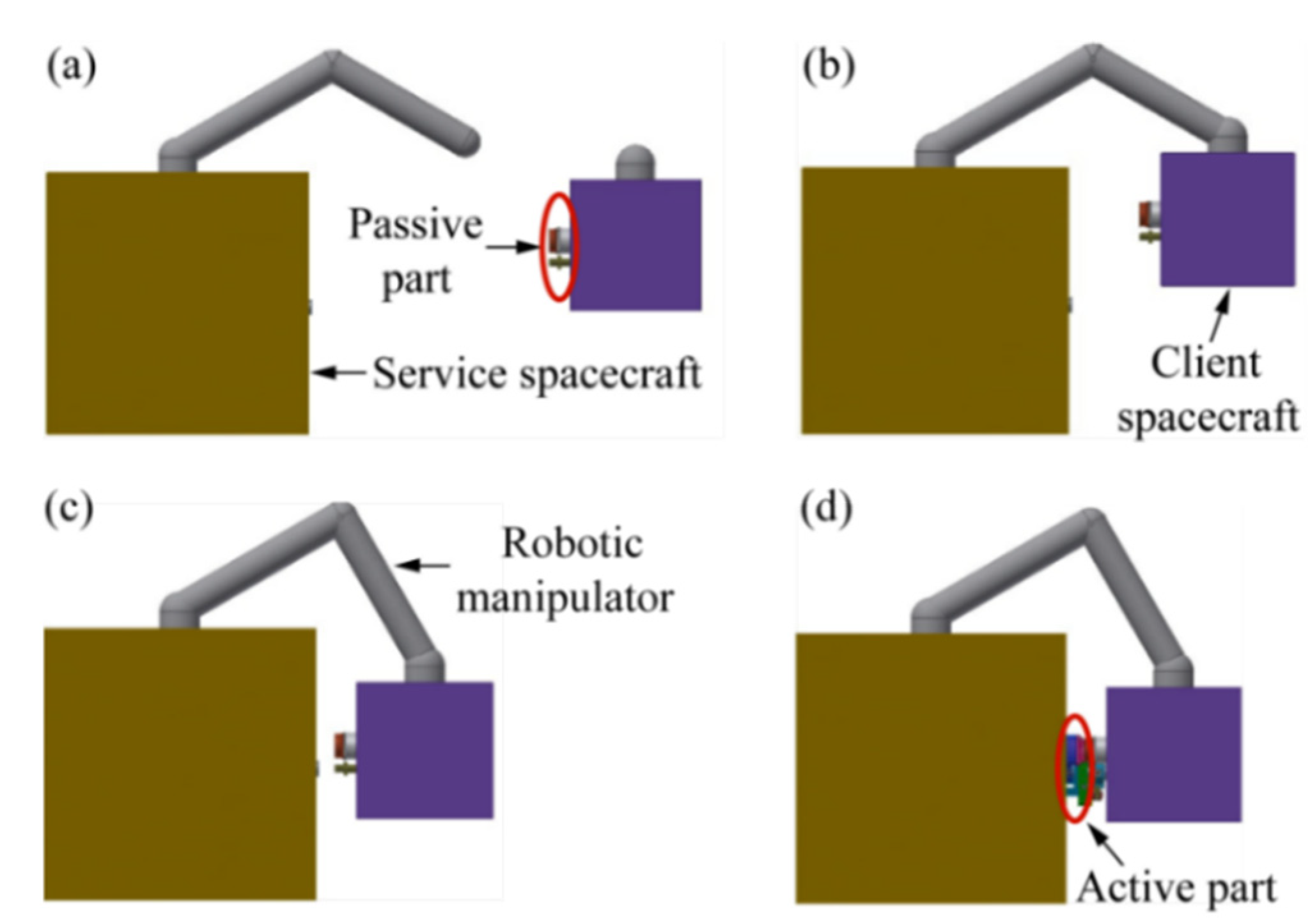
26]. Moreover, compared with the two types of berthing, the impact force of stretching is much lower than that of pulling back due to the lower moving mass. Thus, berthing and joining by stretching a docking subassembly to dock has better application prospects for on-orbit joining operations. The steps are shown in
Figure 1 and described as follows:
- (a)
Approach—the service spacecraft moves toward the client spacecraft using a navigation system until the distance between them is below the maximum capture distance.
- (b)
Capture—the service spacecraft captures the client spacecraft using a robotic manipulator.
- (c)
Pullback—the robotic manipulator pulls back and adjusts the attitude of the client spacecraft toward the service spacecraft until the position of the spacecraft falls within the docking conditions. By this time, the relationship between the service spacecraft and client spacecraft is relatively stationary.
- (d)
Docking—the active part of the docking mechanism stretches and eventually docks with the passive part to build a propellant transfer pipeline.
For berthing and joining by stretching, the initial position and attitude deviations be-tween the two spacecraft may occur owing to the flexibility and control error of the robotic manipulator. To eliminate these deviations, it is necessary to enable the alignment of the docking mechanism. Moreover, the self-resetting capability of the docking mechanism is also required to return the docking subassembly back to its initial position and attitude after docking and prepare for the next refueling operation.
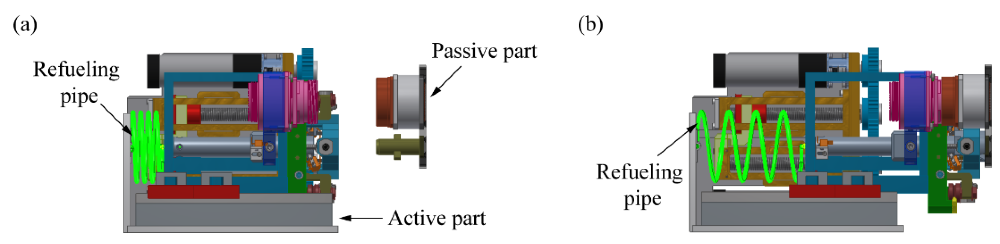
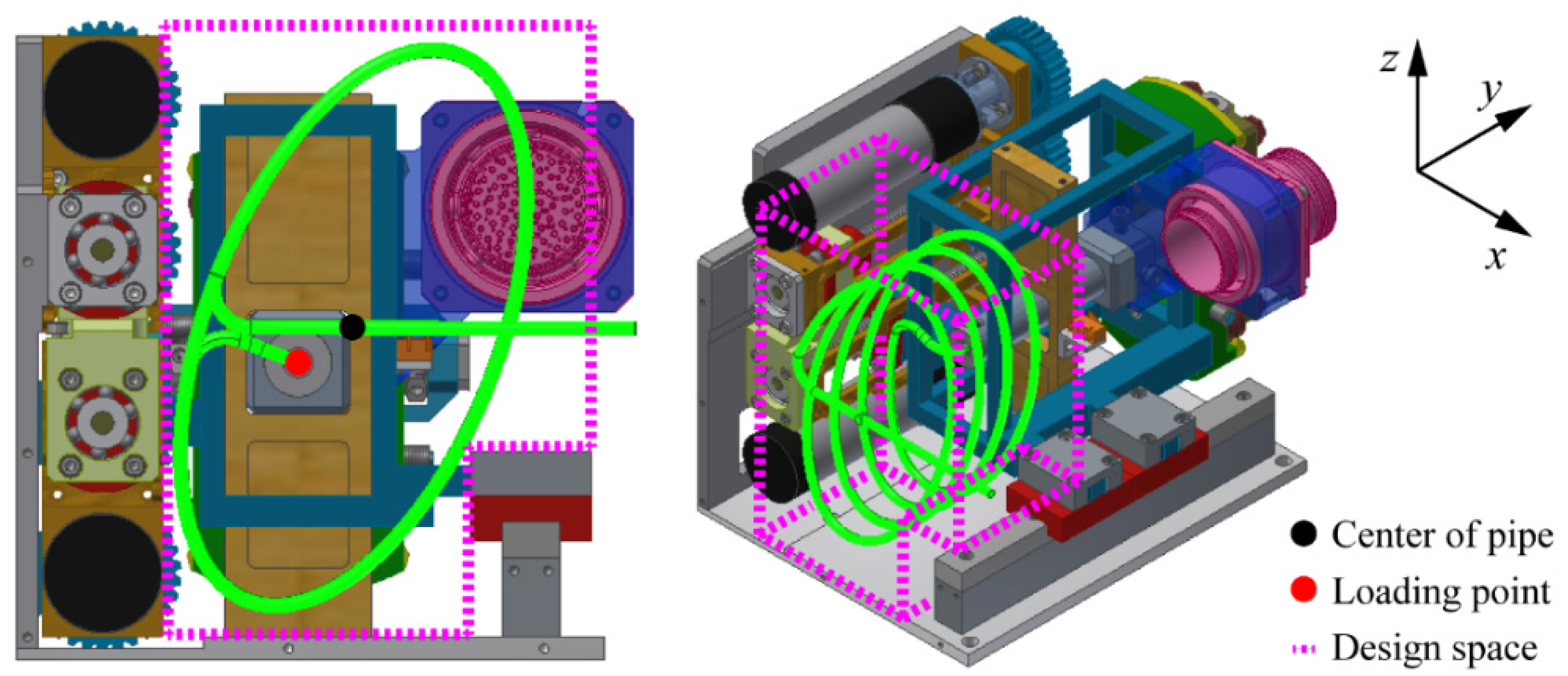
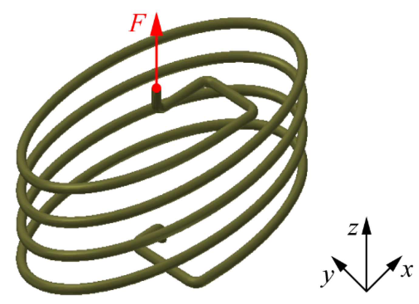
In addition, a refueling pipe connected to the docking subassembly can be stretched synchronously with a docking subassembly during stretching. Considering the compatibility between propellants and the refueling pipe and the high pressure of propellants, the refueling pipe can be generally composed of hard metals, such as titanium or aluminum alloys, rather than flexible materials [
27]. Thus, a nonnegligible additional force on the driving assembly of the refueling pipe should be considered in the design of the docking mechanism. Owing to the single stretching direction of the refueling pipe—that is, the docking direction—a helical configuration is a suitable choice for the refueling pipe to decrease the additional force, as shown in
Figure 2. The mechanical properties of helical pipes—especially axial stiffness—need to be researched, which directly affect the additional force.
At present, scholars have mainly focused on circular-helical structures, such as helical springs. Dym [
28] derived spring rates by Castigliano’s second theorem. Spinella et al. [
29] proposed a type of shape memory alloy (SMA) helical spring for an SMA actuator. Jafari et al. [
30] derived the exact stiffness matrix of curved beams with nonuniform cross-sections by a direct method. Burns [
31] studied the relationship between helical spring compliances and free- and fixed-end rotations. Liu [
32] derived the classical formula for a circular-helical spring using an energy-based method. For the on-orbit mechanism, its design space is limited and irregular. An elliptical-helical refueling pipe is more appropriate in compact docking mechanisms than a circular-helical refueling pipe to further decrease the additional force by increasing the envelope of the pipe (decreasing the axial stiffness of the pipe). However, there is almost no research on elliptical-helical structures. For further design and analysis, the axial stiffness of elliptical-helical pipes must be researched, and the expression of the additional force can be derived by analogy with helical springs.
This paper presents a novel floating docking mechanism for on-orbit refueling by berthing. The capacities of the proposed docking mechanism with passive five-DOF alignment for initial deviations and passive self-resetting for multiple refueling are realized using several spring pins. The mechanism is lightweight, simple, and compact in structure based on the probe–drogue configuration. An elliptical-helical pipe configuration with bias loading was proposed to decrease the additional force on the driving subassembly. Then, the influence mechanism of the additional force of the proposed pipe on the docking process is obtained by mechanical analysis, which determines the design of the spring pins and the driving force. The axial stiffness formula of the proposed pipe is derived using an energy-based method. Finally, simulations and experiments were conducted to evaluate the analyses of the axial stiffness of the elliptical-helical pipe, the contact force, and the tolerance of the mechanism.
The remainder of the paper is organized as follows:
Section 2 describes the structure and working principle of the docking mechanism and the process of docking and the mechanical analysis of docking, which determines the elliptical-helical configuration and the significance of the refueling pipe to the docking mechanism.
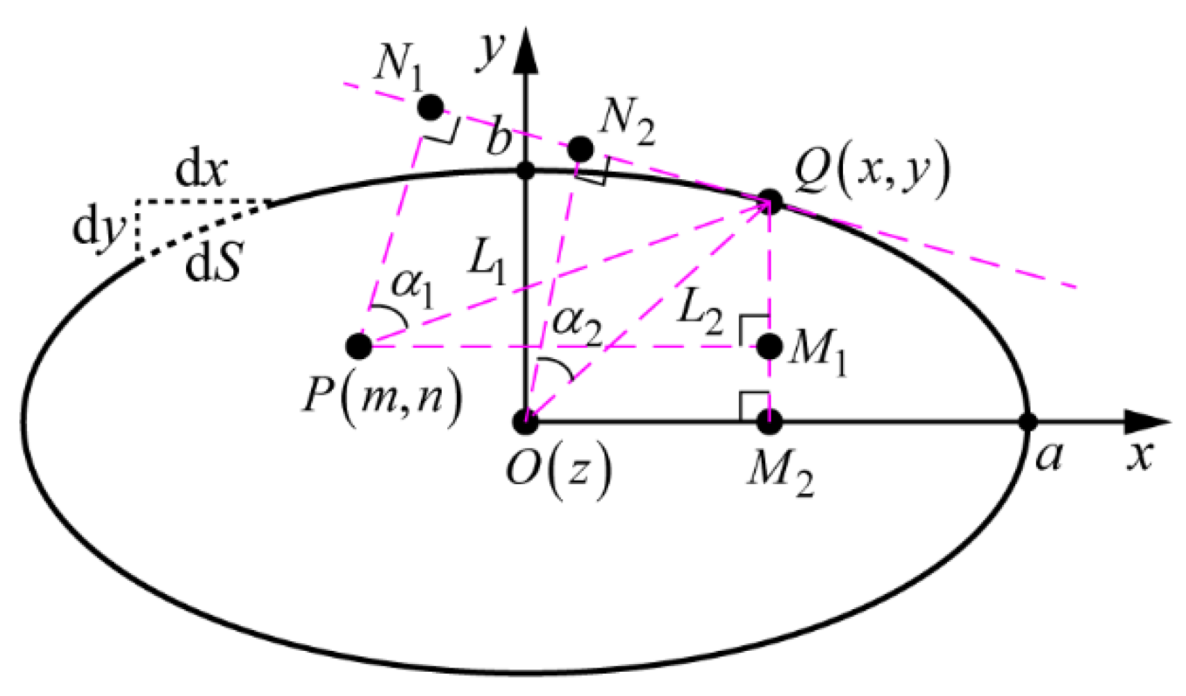
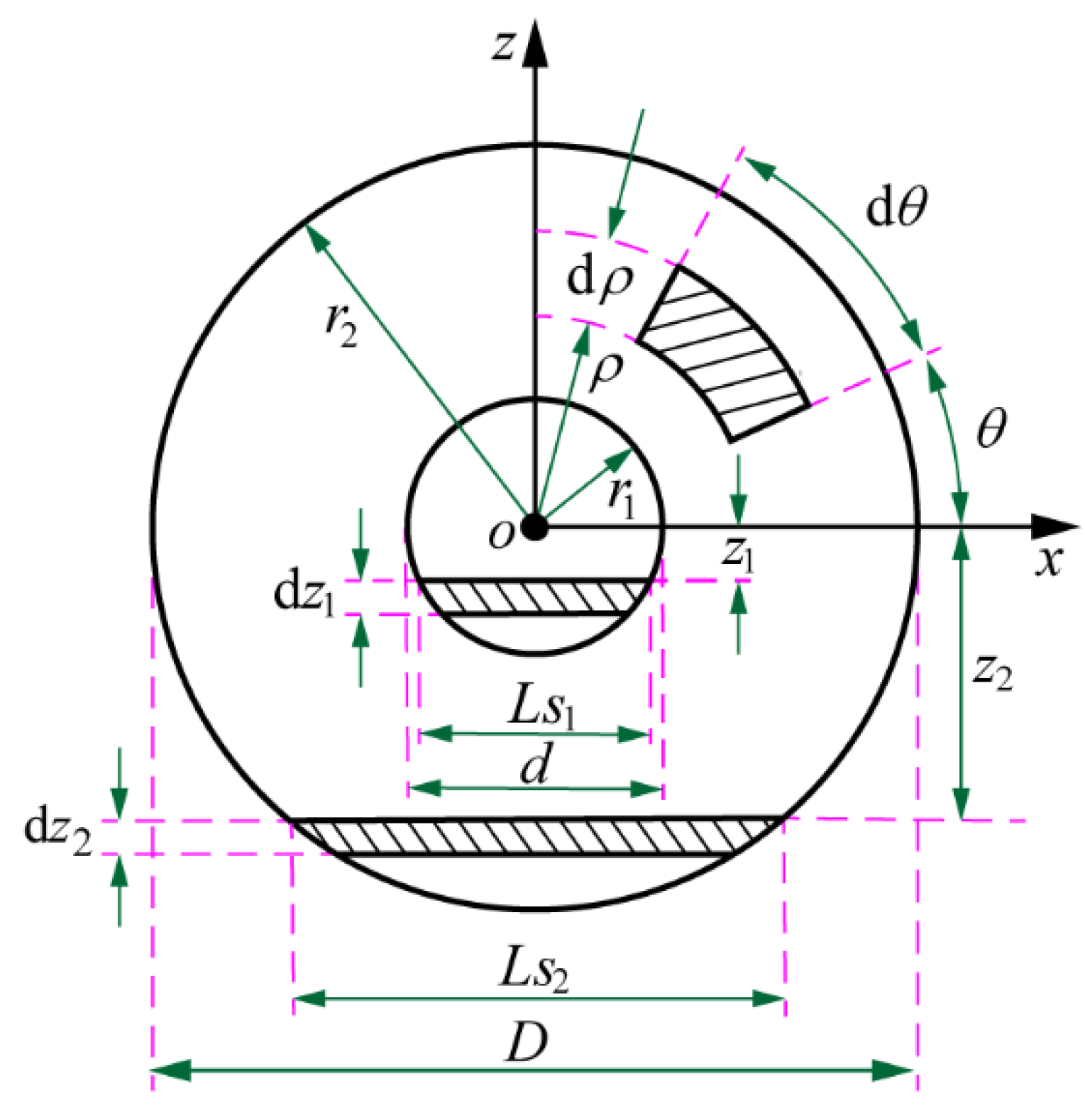
Section 3 describes the building of a model of an elliptical-helical pipe with bias loading and derives the formulas of axial stiffness and maximum stress by the energy-based method and the third strength theory, respectively.
Section 4 presents the simulations conducted to investigate the mechanical properties of the pipe, the contact force, the driving force, and the passive alignment ability of the mechanism, as well as the experiments for validating the simulations. The conclusions are presented in
Section 5.
2. Description of the Mechanism
As mentioned above, the reference scenario considered during the mechanism design is the steps required for berthing docking when a service satellite has captured a client satellite by a robotic manipulator and is ready to dock. The primary function of the docking mechanism is to establish a fluid transfer pipeline between itself and another satellite. In the design of the mechanism, simplicity and low weight are strongly preferred qualities to decrease the driving force during docking.
The application of the docking mechanism proposed in this paper is not restricted to only one type of satellite. The mechanism can be scaled up or down to adapt to the requirements of different missions. In this study, the design of the docking mechanism aims at the on-orbit refueling by berthing for microsatellites. According to the analyses of
Section 1, the design requirements of the docking mechanism can be summarized as follows and the subsequent design need to meet the requirements:
R1—the mechanism shall have five degrees of freedom (DOF) (except in the docking di-rection) alignment abilities to adapt to initial deviations.
R2—the mechanism shall have self-resetting ability for reuse.
R3—the additional force of the refueling pipe needs to be decreased as much as possible to decrease the influences for the docking operation (mainly driving force).
2.1. System Design
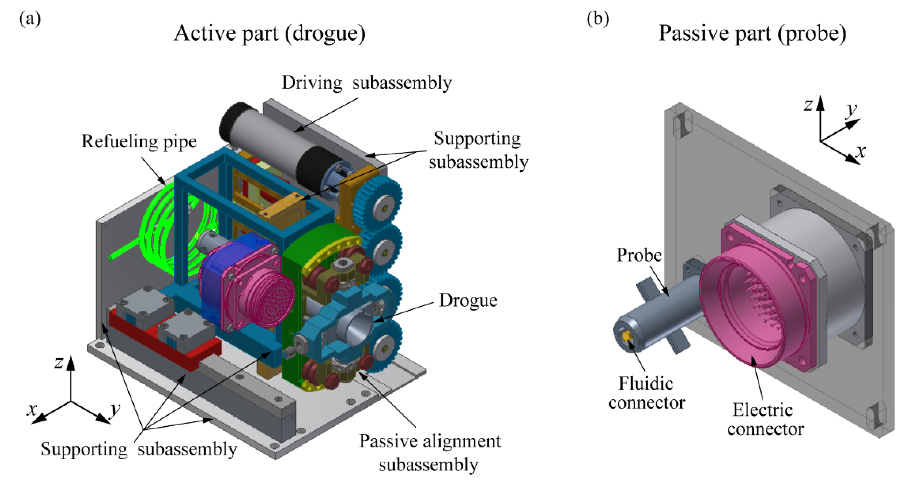
The proposed mechanism adopts the traditional probe–drogue configuration with an active drogue and a passive probe. As shown in
Figure 3 and
Figure 4, the active service part comprises a docking subassembly, passive alignment subassembly, driving subassembly, supporting subassembly, and refueling pipe as the service part. The passive client part consists mainly of a docking subassembly. The basic information of the docking mechanism—i.e., dimension and weight are shown in
Table 1—and the direction definitions of each length are shown in
Figure 3.
The docking subassembly which is made up of probe and drogue, a pair of electric connectors and a pair of fluidic connectors are used for establishing connection between the service and client part. The supporting subassembly is composed of several supporting structures, playing the role of supporting and fixation. As for the passive alignment subassembly, driving subassembly, and refueling pipe, they are core subassemblies of the proposed mechanism and will be introduced in detail below.
2.1.1. Passive Alignment Subassembly
Defining the inertial frame will help describe the adjustment and docking of the mechanism. As shown in
Figure 5, the docking direction and roll axis are on the
y-axis, the horizontal sliding direction and pitch axis are on the
x-axis, and the vertical sliding direction and yaw axis are along the
z-axis.
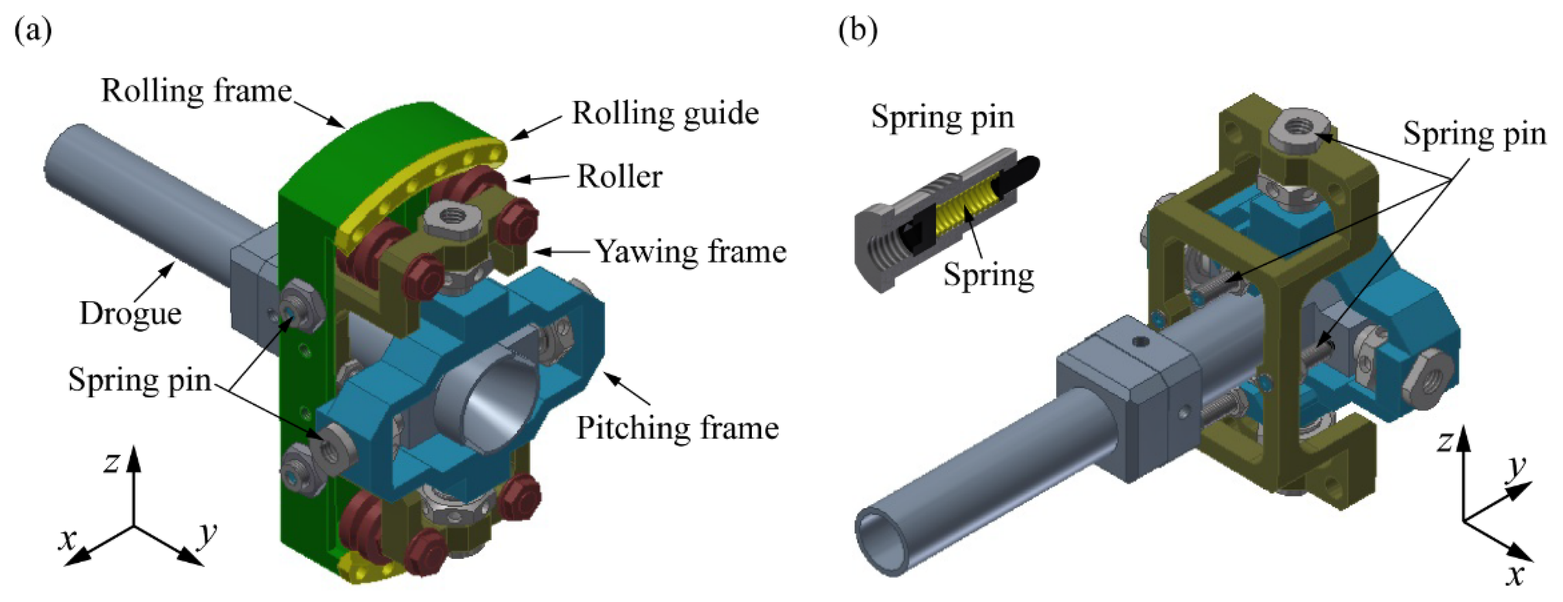
The passive alignment subassembly has the functions of passive alignment and self-resetting in five DOFs, except in the docking direction. The drogue is connected to the passive alignment subassembly to be floating, as shown in
Figure 4a. In this way, the synchronous adjustment and docking of the fluidic and electric connectors can be realized.
A rolling frame, yawing frame, pitching frame, and several spring pins are the main structures of the passive alignment subassembly. The drogue and the pitching frame are connected by two preloading spring pins, which become cylindrical pairs so that the drogue can slide and rotate along the x-axis to adapt to deviations. The pitching frame and the yawing frame are also connected by two preloading spring pins, such that the pitching frame can slide and rotate along the z-axis to adapt to deviations. The yawing frame and the rolling frame are connected by four rollers, which can roll on the rolling guide so that the yawing frame can rotate along the y-axis to adapt to deviations.
A pair of the same preloading spring pins is needed for each DOF to maintain the drogue at an initial state of position zero. During the docking process, the drogue will ad-just passively to adapt to deviations so that the spring force of the spring pin pairs will change (the spring pin along the adjustment direction will be compressed, and the spring force of the pin increases continuously, and another pin is out of contact with the corresponding connecting frame to be inactive), thereby generating a reset force or torque, which will reset automatically after refueling and separating from the docking mechanism. The principle of the passive alignment subassembly is shown in
Figure 5. The docking mechanism is floating and reusable because of passive adjustment and self-resetting characteristics, which meet the requirement R1 and R2. The tolerance range of the passive alignment subassembly are shown in
Table 2.
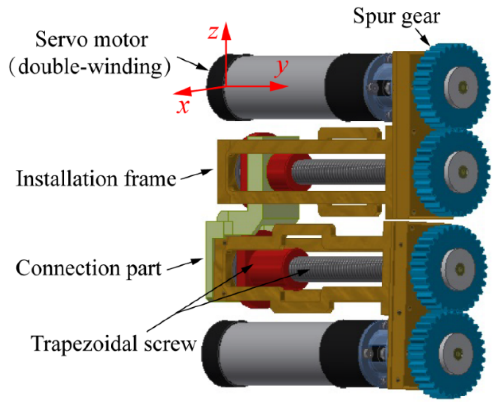
2.1.2. Driving Subassembly
The driving subassembly consists of two identical driving modules. Each module consists of a servo motor (double-winding), two identical spur gears, a trapezoidal screw, and an installation frame, as shown in
Figure 6. The servo motor drives the spur gears, stretching the trapezoidal screw which is indirectly connected with the drogue, both of which are attached to the installation frame to form a module, and the trapezoidal screw locks the driving subassembly by its self-locking. Under normal conditions, the lower driving module works alone and drives the drogue to dock; as the backup, the upper driving module will work and drive lower module one to stretch by part connecting the two modules, thus ensuring the success of docking if the lower driving module does not work. This will increase the reliability of the driving subassembly by four times (as the servo motors are double-winding). The upper installation frame is the fixed end secured by the supporting subassembly. The properties of the driving subassembly are shown in
Table 3.
2.1.3. Refueling Pipe
As
Figure 2 and 3 show, the refueling pipe is connected to the drogue and stretched along with the docking subassembly under berthing docking; this pipe is generally made of hard metal. Thus, the refueling pipe generates an additional force on the driving subassembly during the docking process, as mentioned in
Section 1. A helical configuration for the refueling pipe is an excellent choice for linear tension and compression motion to decrease this additional force. In the context of this paper, the refueling pipe needs to stretch and retract repetitively, meaning that its initial and terminal states must be designed to correspond with compression and tension, respectively, for an equal axial deformation; this is to ensure that the maximum additional force of the two states is equal and the lowest. The additional force generated by the refueling pipe also influences the design of the driving force and spring pins, as explained in
Section 2.3. Given the necessary compactness of on-orbit mechanisms, the design space of the refueling pipe is limited and irregular; hence, an elliptical-helical configuration with bias loading is proposed to replace the circular-helical configuration and decrease the additional force, as shown in
Figure 7. The expressions of axial stiffness and strength checking of this type of pipe are derived in
Section 3.
2.2. Docking Process
As mentioned in
Section 1, refueling spacecraft must complete the “approach”, “capture”, and “pullback” steps before “docking” under the berthing docking. In this section, the sequences of the docking process are designed, as shown in
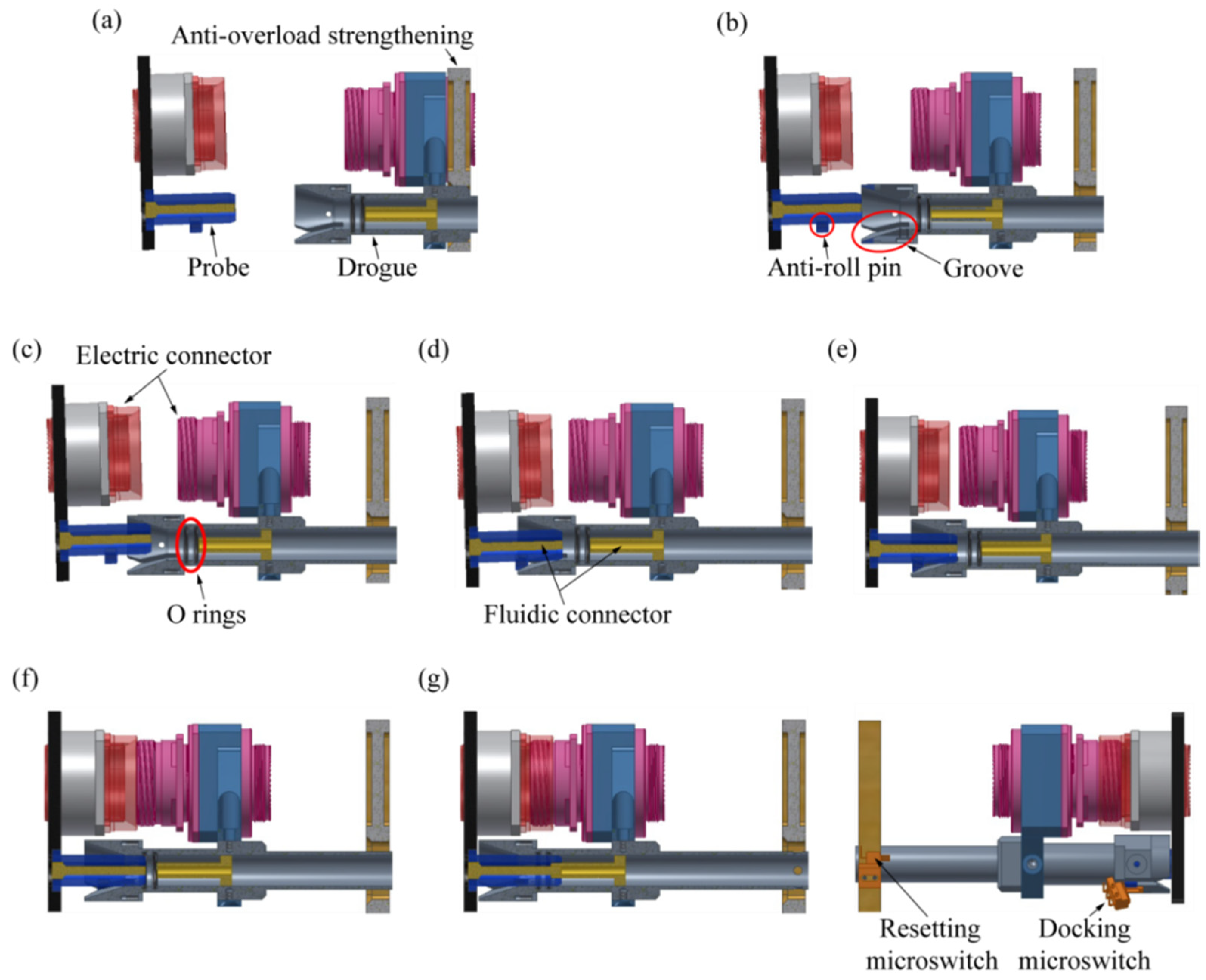
Figure 8.
The detailed descriptions of the docking process are as follows:
- (a)
Initial—the positions of two satellites under the docking conditions in which the probe enters the acceptance range of the drogue; the drogue is still supported by anti-overload strengthening.
- (b)
Approach—the system powers on, and the drogue stretches and breaks away from the anti-overload strengthening to be floated; at the same time, the probe is ready to enter into the drogue.
- (c)
Contact and alignment I—the drogue stretches continuously to contact with the probe; the contact force adjusts deviations in the X and Z linear directions to achieve the correct alignment.
- (d)
Probe insertion and alignment II—the probe is inserted in the hole of the drogue; the contact torque adjusts deviations in the pitch and yaw directions to achieve the correct alignment.
- (e)
Pin insertion and alignment III—the anti-roll pins contact the grooves; the contact torque adjusts the deviation in the rolling direction to achieve the correct alignment fully.
- (f)
Connector docking—the position and attitude of the electric connector and the fluidic connector are corrected; two connectors are ready to dock.
- (g)
Accomplishing—the drogue is inserted continuously until the electric connector and the fluidic connector reach the designed location; the whole docking is accomplished.
So far, the design of the docking mechanism is completed (except for the refueling pipe), and there are some notes need to be paid attention:
- (1)
The drogue is not fluid-filled before accomplishing docking.
- (2)
Two O-rings are installed in the hole of the drogue and used to prevent fluid leakage when the male fluidic connector breaks away from the female fluidic connector during separation.
- (3)
Two docking microswitches are installed beside the two grooves, and the system powers off when the anti-roll pins trigger either of the two microswitches upon the completion of docking; a resetting microswitch is also installed on the anti-overload strengthening and the system powers off when the drogue triggers the microswitch upon the completion of resetting.
- (4)
The trapezoidal screw locks the system by its self-locking.
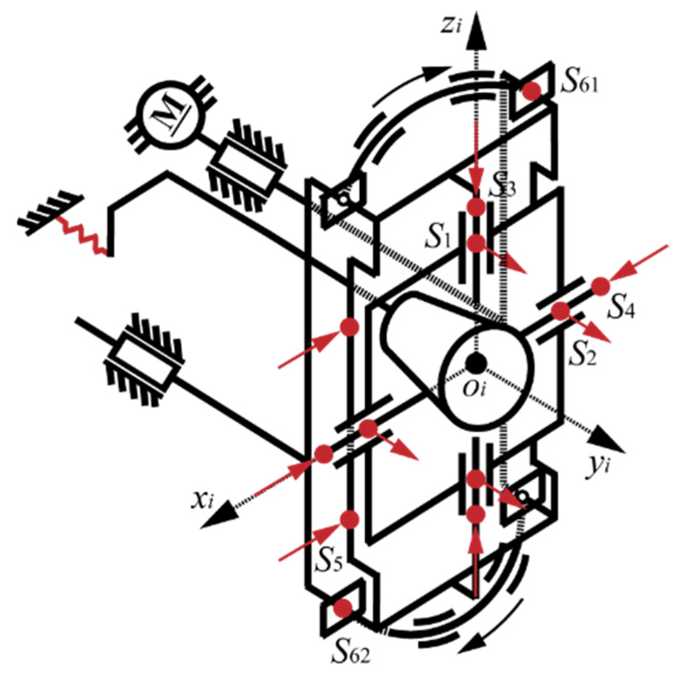
2.3. Mechanical Analysis
In
Section 2.1.1, the design requirements R1 and R2 have been met. As another core design criteria, R3 must decrease the driving force during the docking process to decrease the power consumption of the motor and facilitate successful docking. In this section, the mechanical analysis of the system, which was used to guide the design of the driving force, is discussed. The drogue is in a state of low speed and uniform motion throughout the docking process; thus, the docking can be considered as a quasi-static process. The kinematic diagram of the mechanism is shown in
Figure 9.
From the viewpoint of the docking process, as shown in
Figure 8, the mechanical analysis can be divided into three parts:
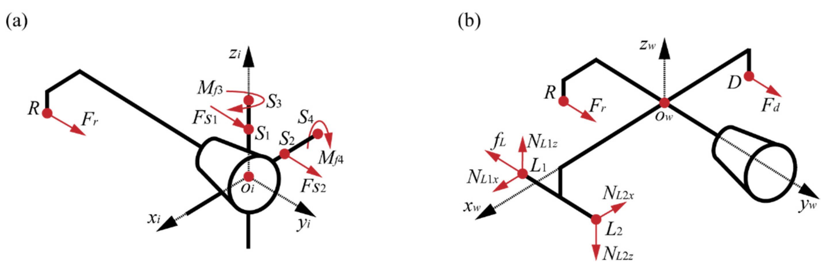
The (a) initial and (b) approach stages of docking comprise the process of free stretching and do not involve contact. The drogue stretches and breaks away from the anti-overload strengthening to float. Owing to the characteristics of the elliptical-helical configuration with bias loading of the refueling pipe, the bias torque generated by the pipe acts on the drogue. To maintain the initial attitude of the drogue, the corresponding spring pins must have sufficient preloading to compete with the bias loading of the pipe, or the drogue will slant, and the initial deviations will increase, resulting in failed docking. The free-body diagram of the initial floated state is shown in
Figure 10a, and the preloading conditions of the corresponding spring pins can be obtained by the following equation:
where
Fis1 and
Fis2 are the preloading of the resetting spring pins for pitching and yawing respectively,
Fr is the axial force of the refueling pipe,
μs is the friction coefficient of the spring pins and frame,
rs is the radius of spring pins,
S1 is the point at which the resetting pitching spring pin acts on the yawing spring pin,
S2 is the point at which the resetting yawing spring pin acts on the pitching spring pin,
R is the point at which the refueling pipe acts on the drogue,
S1S3 and
S2S4 represent the yawing and pitching spin axes respectively, and
x and
z represent the distance between a point corresponding to the subscript and another axis; for instance,
zs1 represents the distance between point
S1 and
xr-axis.
Then, the drogue stretches at a constant, continuous speed until it contacts the probe. The servo motor generates the driving force of the drogue to compete with the resistance forces, including the axial force of the refueling pipe and the friction of the linear guide-way. The spur gears and trapezoidal screw of the driving subassembly lead to an efficiency loss of the driving force. The free-body diagram of the free stretching process is shown in
Figure 10b, and the driving force can be obtained using the following equation:
where
Fd is the driving force,
ηg and
ηs are the efficiency of the spur gears and trapezoidal screw,
μL and
fL are the friction coefficient and friction of the linear guideway,
D is the point of action of the driving force,
L1 and
L2 are the endpoints of the linear guideway,
NL1x and
NL2x are the supporting forces of points
L1 and
L2 along
xw-axis, and
NL1z and
NL2z are the supporting forces of points
L1 and
L2 along
zw-axis.
- 2
Contact and alignment
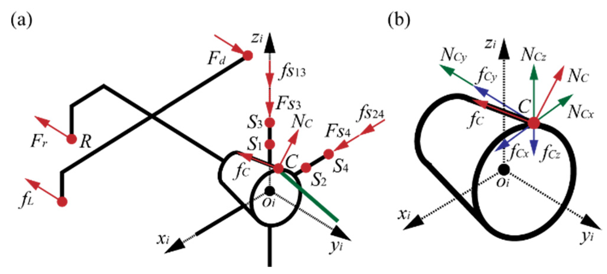
The drogue and probe must then make contact and self-align by completing steps (c), contact and alignment I; (d), probe insertion and alignment II; and (e), pin insertion and alignment III. Through this process, the drogue makes contact with the probe and must compete with the spring force of the pipe, the friction of the linear guideway and linear spring pins, and the contact force is affected by the spring force of the spring pins. Considering step (c) as an example to summarize the factors influencing the driving force, a free-body diagram of this step is shown in
Figure 11, and the driving force can be obtained by the following equation:
where
Nc and
fc are the component forces of the contact force, representing the normal contact force and the tangential contact force, respectively, acting on the drogue through the probe. The subscripts represent the direction of the component force, representing the component force of
Nc along the
y-axis, and
Fs and
fs are the spring force and the friction of the linear spring pins along the corresponding axis acting on the drogue.
In step (c), the contact force is related to the spring forces of the two linear spring pins. Similarly, the contact force of process (d) is related to the spring forces of the yaw and pitch spring pins and (e) to that of the roll spring pins; thus, the driving force is determined by the contact force. Therefore, decreasing the spring force (preloading and axial stiffness) of the spring pins decreases the driving force.
- 3.
Accomplishing and resetting
After the process of contact and alignment, the drogue has achieved the correct alignments and is ready for step (f) and connector docking. By this time, the spring pins have reached the maximum amount of compression, and the spring forces compressed the drogue on the probe. Thus, the driving force of process (
f) can be obtained using the following equation:
where
fdp is the friction between the drogue and probe, and
Fie is the insertion and extraction forces of the fluidic and electric connectors.
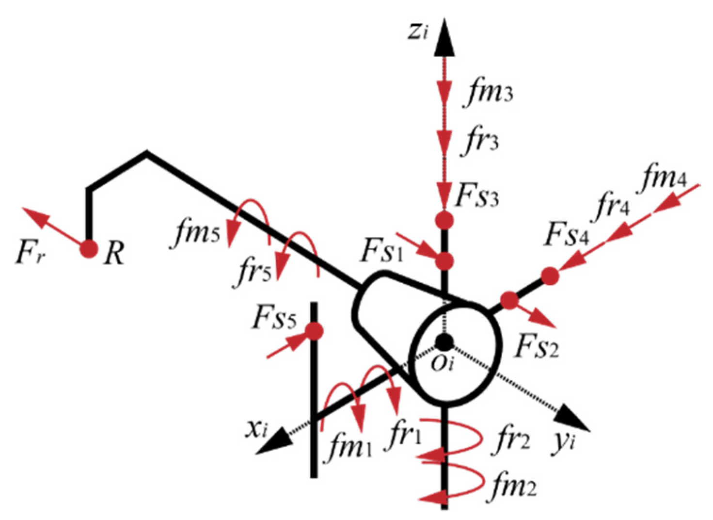
After process (f), the docking process is complete, and the mechanism refuels the client craft. The drogue will separate from the probe after refueling, and to ensure that the docking mechanism can be reused, the preloading of the spring pins must be high enough to reset the drogue. Considering the extreme case, the drogue does not reset until it completely breaks away from the probe. The preloading of spring pins must be greater than the friction in the corresponding joints caused by the compression of the helical refueling pipe and the precompression caused by machining accuracy and assembly errors, as shown in
Figure 12. Thus, the resetting conditions of the corresponding spring pins can be obtained using the following equation:
where
i represents the five joints for alignment,
Fs is the preloading of the spring pin,
fr is the friction generated by the compression of the refueling pipe acting on the kinematic pair, and
fm is the friction of the kinematic pair caused by machining accuracy and assembly errors.
The conclusions reached through the mechanical analysis of each process are summarized below:
- (1)
The spring force of the helical refueling pipe exists throughout the docking process and cannot be ignored as one of the resistances of the driving force.
- (2)
The driving force is related to the contact force, which is related to the preloading and axial stiffness of the spring pins.
- (3)
The preloading and axial stiffness designs of the spring pins are based on the pre-loading condition (Equation (1)) and the resetting condition (Equation (5)), which are related to the axial force of the helical refueling pipe.
- (4)
As a precondition for satisfying the preloading and resetting conditions, the axial stiffness of the spring pins should be as low as possible to prevent an increased con-tact force.
In summary, decreasing the axial force of the helical refueling pipe can significantly decrease the driving force of the docking mechanism. Thus, the structural and mechanical property design of helical refueling pipes is a significant area of research. In addition, the design space for the refueling pipe is irregular because of the compactness of the on-orbit mechanisms. Therefore, an elliptical-helical pipe with bias loading may be a better choice for the refueling pipe, as its envelope is larger, which means the axial stiffness is lower, and the mechanical properties of the pipe are analyzed in
Section 3.
4. Analysis and Discussion of Simulations and Experiments
After the design and mechanical analyses of the mechanism, three types of numerical simulations are performed in this section to investigate the static behavior of the refueling pipe and the kinematic and dynamic behavior of the docking mechanism: (1) a static simulation of the mechanical properties of the refueling pipe, (2) a kinematic simulation of the tolerance range of the docking mechanism, and (3) a dynamic simulation of the contact force and driving force of the docking mechanism. Corresponding experiments are per-formed to validate the simulations.
4.1. Static Analysis of a Refueling Pipe
The static simulation and experiment on the mechanical properties of the refueling pipe are performed in this section to verify the accuracy of the analytical solution (Equations (20) and (26)).
An ABAQUS simulation was performed for comparison with theoretical results. The parameters of the numerical validation model of the elliptical-helical pipe with bias loading are listed in
Table 4.
By substituting the parameters into Equations (20) and (26), the theoretical results of the numerical validation model can be obtained as follows:
where the subscript ‘t’ refers to the theoretical result.
The axial deformation of the helical part is denoted as
λt. However, in actual conditions, each end of the pipe is connected to the drogue and propellant tank. As shown in
Figure 13, these connecting parts resemble cantilever beams whose deformation can be calculated by the mechanics of materials [
32]. For the numerical validation model in
Table 3, the deformation of the connecting part is 0.25 mm.
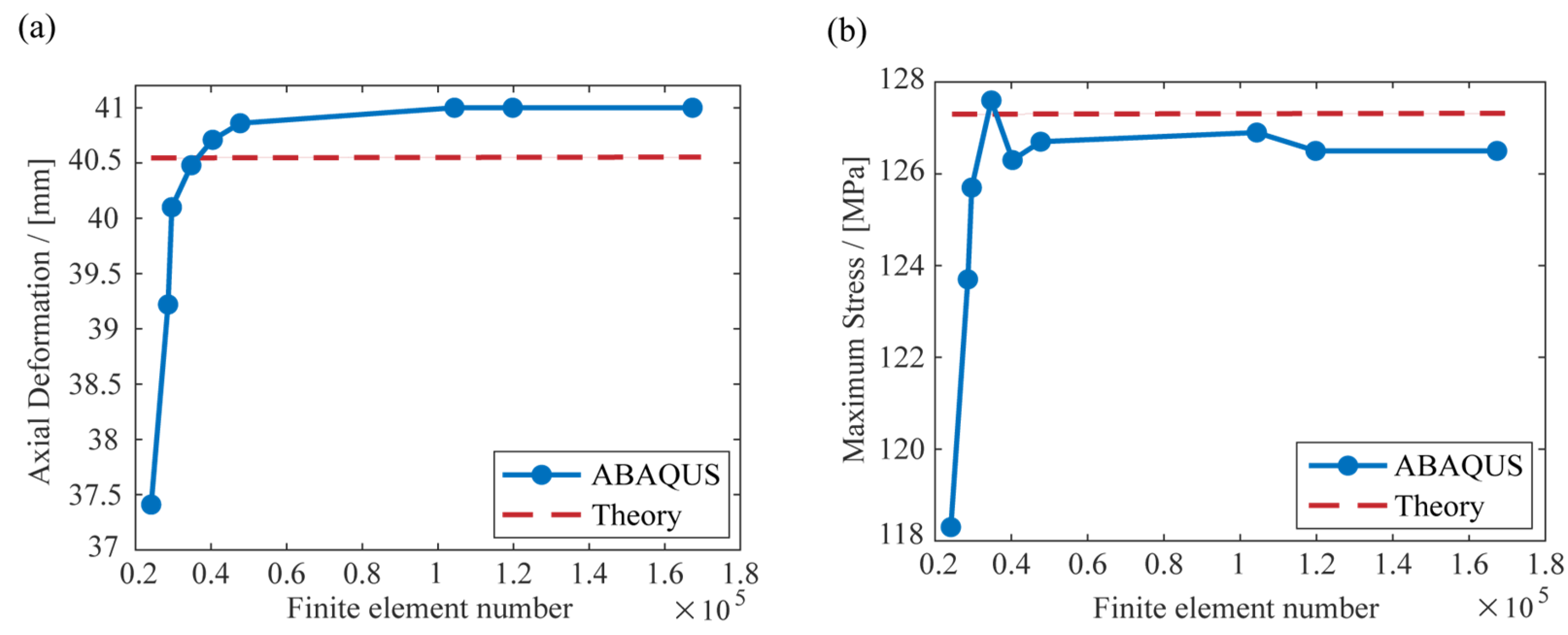
The third strength theory is used as the strength-checking formula in this study, but the fourth strength theory is used in ABAQUS. To compare the strength-checking result with ABAQUS σmax t is calculated again by the fourth strength theory (0.866 times as much as the third strength theory), which is 127.3 MPa.
Thus, Equation (28) is updated to create Equation (29):
When ABAQUS is used to simulate the model above, the results slightly approach the theoretical results as the number of finite elements increases, as shown in
Figure 16. Finally, the results converge when the number of finite elements is more than 1.2 × 10
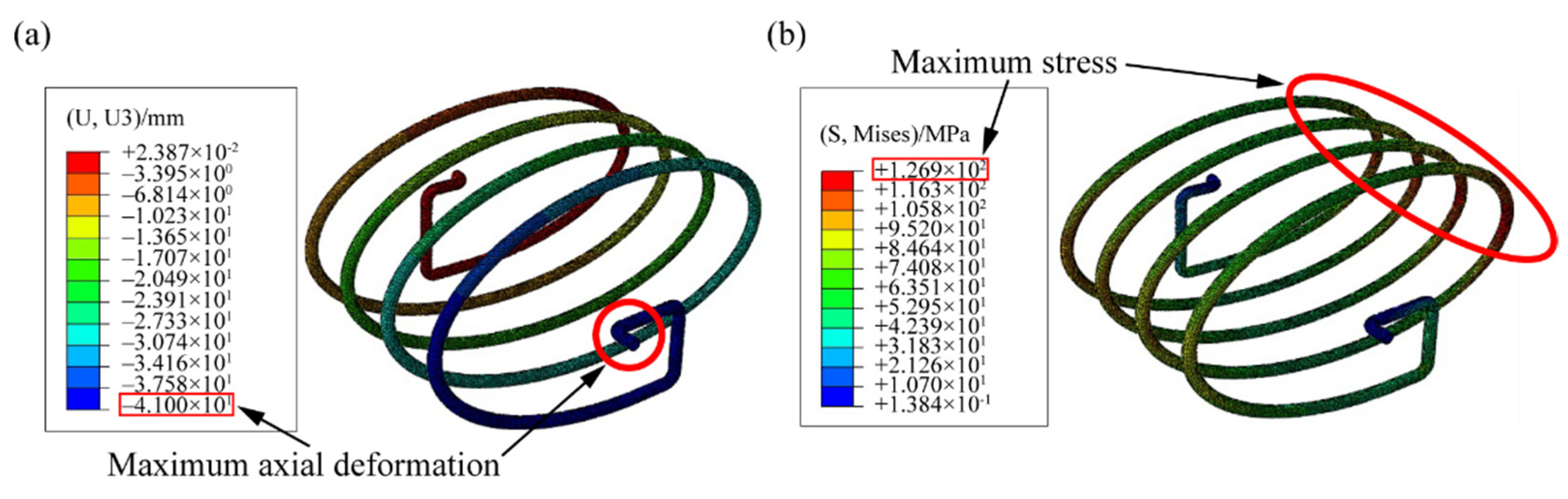
5 and the converged results of simulation are shown in
Figure 17. The values of
λA and
KA are obtained using the following equation:
where subscript ‘A’ refers to the ABAQUS result.
Compared with the theoretical results and simulation results—i.e., Equations (29) and (30)—the relative errors of the axial deformation and maximum stress are less than 1.2% and 0.6%, respectively, which verifies the validity and accuracy of the analytical solution. Because the effects of the pitch angle are neglected in the present study, the theoretical axial deformation result is lower than the ABAQUS result.
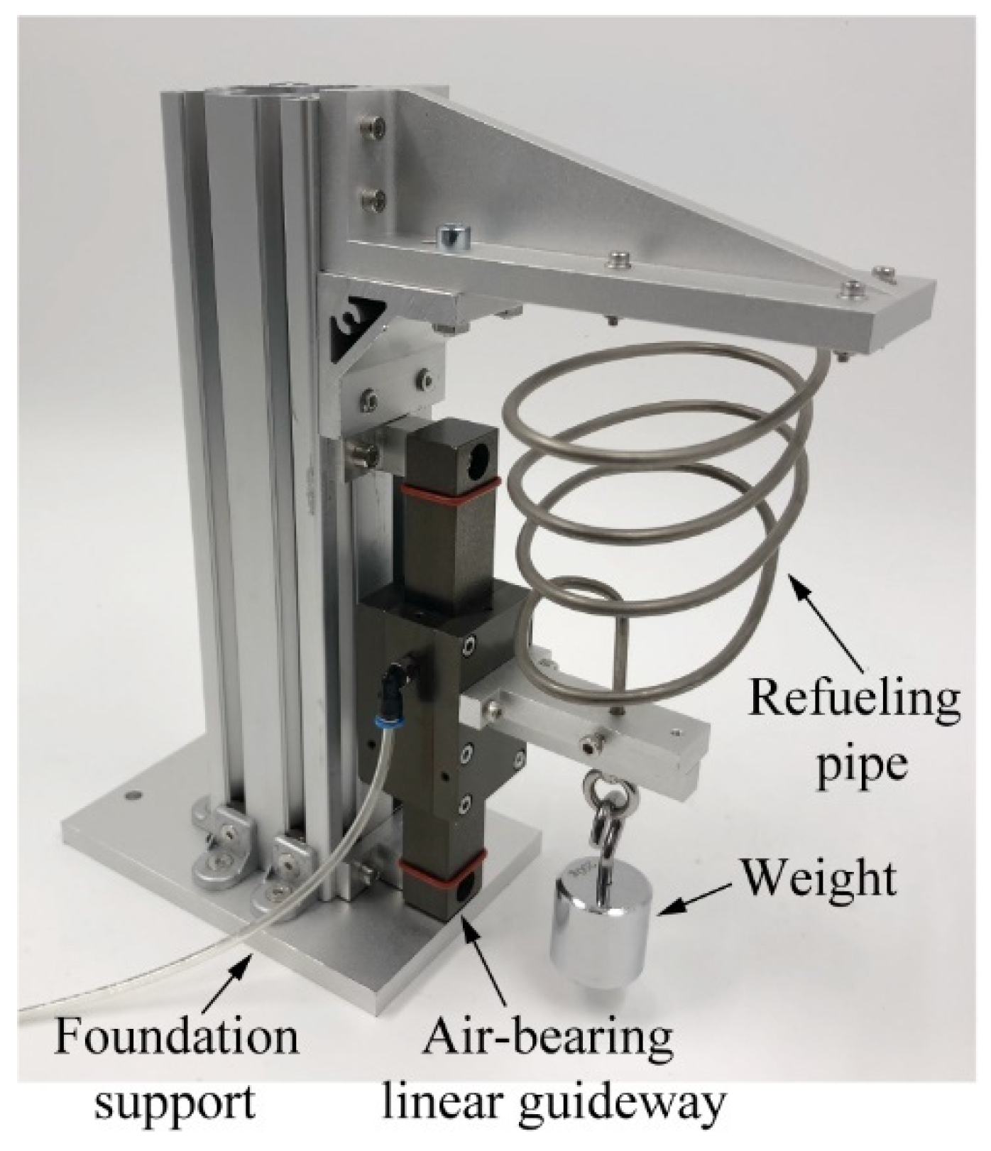
Then, an experiment was performed to validate the theoretical results and the simulation of the axial stiffness of the pipe. As shown in
Figure 18, the experimental system consists of foundation support, an air-bearing linear guideway, a weight, and a refueling pipe. Because of the bias loading characteristic of the refueling pipe, an air-bearing linear guideway is used in the experiment to keep the pipe moving in a straight line to test the axial stiffness, and the low friction coefficient of the air-bearing linear guideway does not generate additional resistance, which will not affect the accuracy of the experiment.
By hanging weight underneath the pipe (as in the simulation), the elongation λe can be tested, and the axial stiffness of the refueling pipe Ke: Ke = 0.2579 N/mm. Comparing the experimental and theoretical results, the relative error of the axial stiffness is less than 4.4%, which validates the accuracy of the theoretical formula (Equation (20)). Thus, the theoretical formulas can guide the design of an elliptical-helical pipe with bias loading.
4.2. Kinematic Analysis of the Docking Mechanism
A kinematic simulation and experiment on the tolerance range of the docking mechanism are performed in this section to verify R1 and R2.
First, a RecurDyn simulation was performed. The 3D model is directly imported from the model reported in
Figure 3, and the kinematic diagram of the docking mechanism is shown in
Figure 9. The probe is fixed, and the servo motor drives the drogue with a five-DOF adjustment to dock with the probe. By changing the initial state (the linear and angular misalignments between the probe and the drogue), the tolerance range of the docking mechanism can be ascertained by simulation.
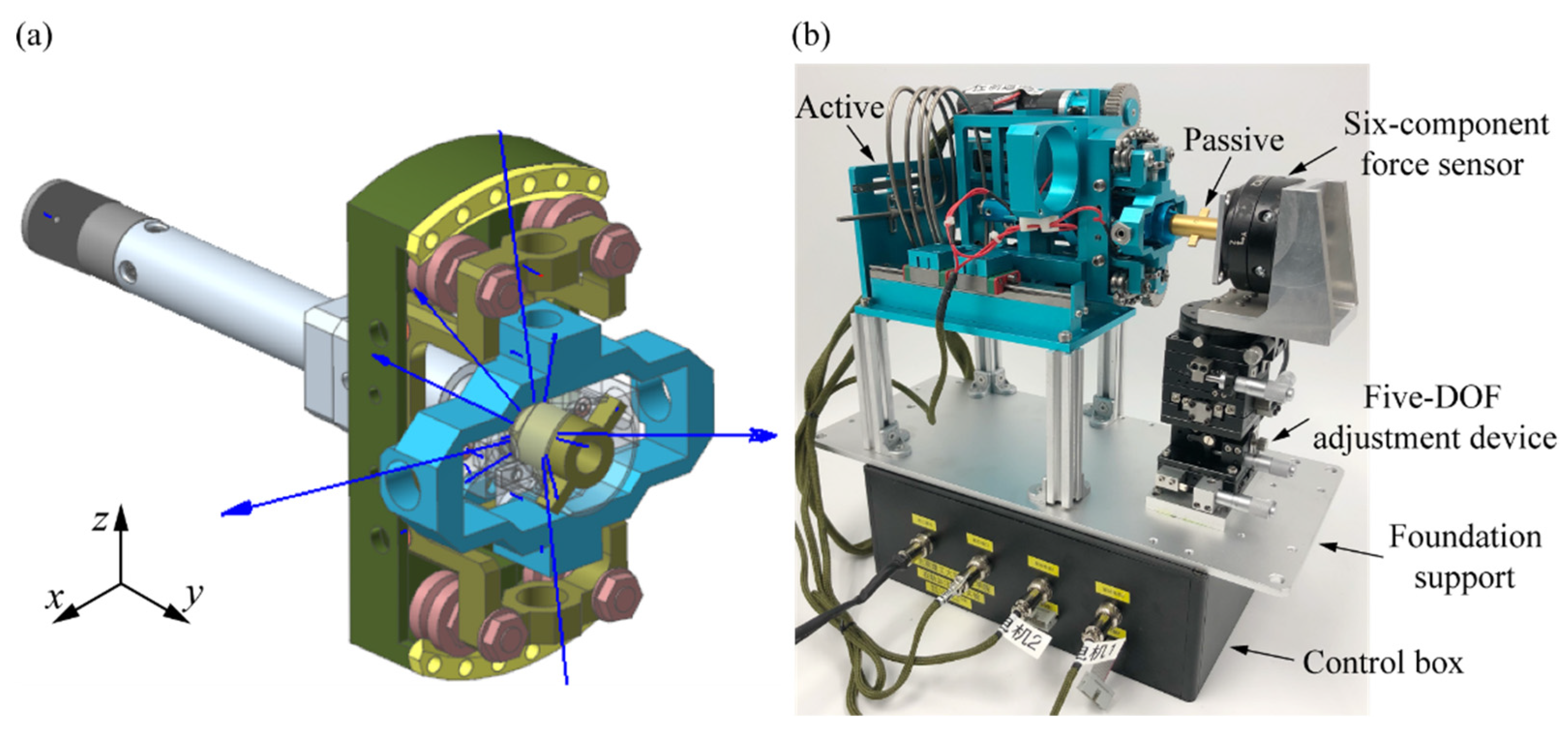
An experiment was then performed to validate the simulation results of the tolerance range. As shown in
Figure 19, the experimental system consists of a docking mechanism (including an active part and a passive part), foundation support, an adjustment device with five DOFs (except in the docking direction), a six-component force sensor used for the dynamics experiment in the next section, and a control box. The five-DOF adjustment device, whose accuracy is 0.01 mm and 0.01°, is decoupled so that it can adjust for each DOF alone. Through the adjustment device, the experiment can recreate the working conditions of the simulation to validate the results of the tolerance range of the docking mechanism.
Using this design, the tolerance range of the docking mechanism was estimated. To validate the theoretical range, working conditions must be chosen around the boundaries of the theoretical range. In addition, by considering the central symmetry of the passive alignment subassembly, a quarter of the working conditions are sufficient to validate the range. Thus, nine types of working conditions were tested in the simulations and experiments, as shown in
Figure 20. In presenting the results, the horizontal and vertical axes represent two linear and three angular deviations, respectively. For example, point (−2, −1) reveals that the initial deviations between the drogue and the probe are (−2 mm, −2 mm, −1°, −1°, −1°); in the simulations and experiments reproducing these deviations, docking is successful. The kinematic simulations and experiments verified the validity of the estimated tolerance range (±4 mm on two linear directions and ±2.5° on three angular directions).
4.3. Dynamics Analysis of the Docking Mechanism
A dynamic simulation and experiment on the contact force and driving force of the docking mechanism are performed in this section to verify the positive influence of the elliptical-helical refueling pipe on the docking mechanism with bias loading. The simulation and experiment took no account of gravity.
As discussed in
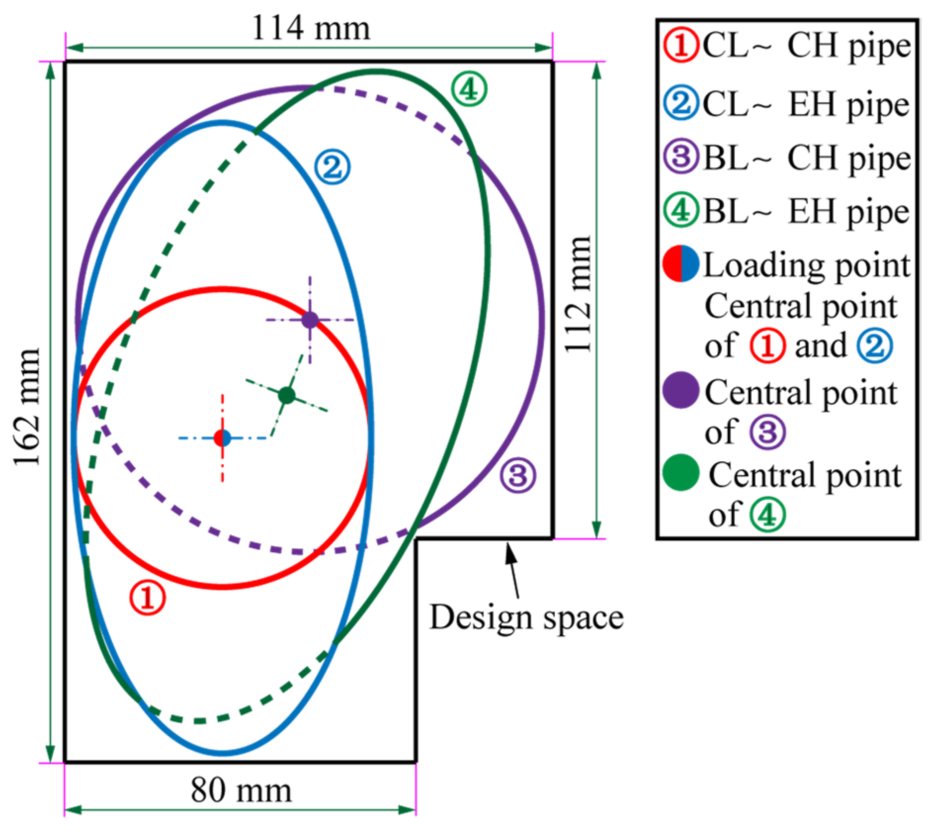
Section 2.3, the driving force is determined by the preloading and axial stiffness of the spring pins, and these characteristics of the spring pins are determined by the spring force of the refueling pipe. Therefore, decreasing the spring force of the refueling pipe can significantly decrease the driving force of the docking mechanism. A helical structure can decrease the resistance further for motion in a straight line, so a circular-helical pipe with center loading is proposed for such an application. By considering the loading point and the design space, as shown in
Figure 7, three other types of analogical pipes can be proposed: a circular-helical pipe with bias loading, elliptical-helical pipe with center loading, and elliptical-helical pipe with bias loading, as shown in
Figure 21. In addition, the preloading condition (Equation (1)) and the resetting condition (Equation (5)), each type of pipe can be matched with a set of spring pins, as shown in
Table 5 and
Table 6.
In this section, two types of dynamic simulations (contact force and driving force) were performed for four types of pipes (using the optimal configuration of axial stiffness for each type) and the corresponding pairs of spring pins. The simulation of the contact force is intended to verify the validity of the dynamic models. The simulation of the driving force is thus to show the superiority of the configuration using the elliptical-helical pipe. The 3D model is the same as that used in the kinematic simulation.
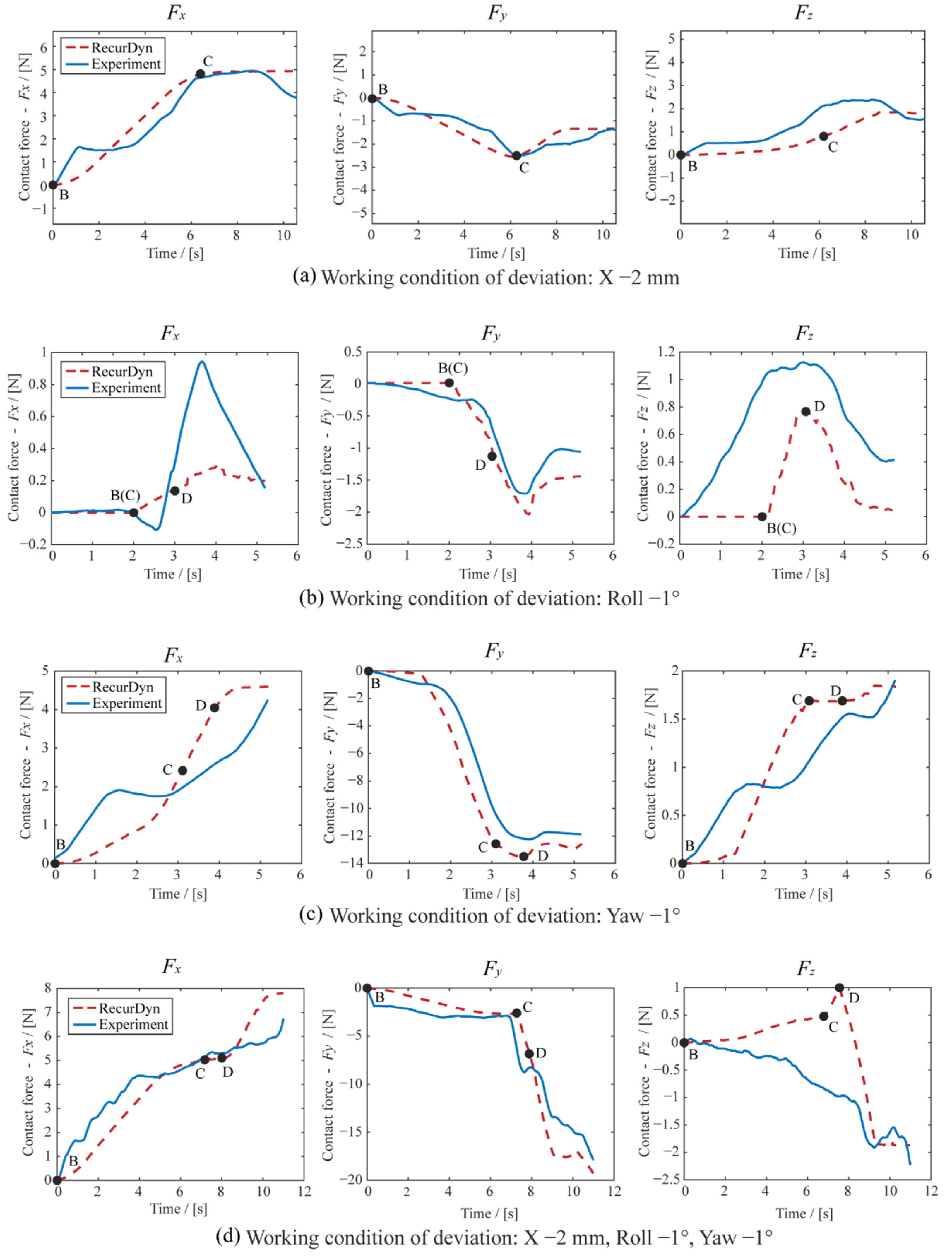
For the simulations of contact force, four types of working conditions are sufficient to verify the validity of the dynamic model, including three typical decoupling conditions, (
X −2 mm), (Roll −1°), (Yaw −1°), and one typical coupling condition, (
X −2 mm, Roll −1°, Yaw −1°). Then, corresponding experiments were performed to validate the results of the simulations. The dynamic experimental system is the same as that used in the kinematic experiment system, as shown in
Figure 19. A six-component force sensor installed at the root of the probe is used to detect contact forces. The key positions of the docking are shown in
Figure 22, used to support dynamic results.
The results of the contact force simulations and experiments are shown in
Figure 23. Four types of working condition are setting, which can cover the whole docking conditions. The points worth noticing are points B, C, and D, which are the turning points of docking state. The curve worth noticing is
Fy, which is the contact force of the docking direction and influence the driving force directly. As shown in
Figure 23, the trends (especially curve
Fy) and most of the values (especially points C and D) of the experiment curves can correspond by the simulation curves. In view of machining errors, sensor accuracy and the estimation of friction coefficient, the agreements between simulations and experiments are more than 70% and the key points and curves are more than 85%, which reciprocally verifies the validity of the simulations and experiments. Therefore, the driving forces of the mechanism with four types of pipes above can be obtained from the simulations instead of experiments, which can save time and resources, to verify the superiority of the proposed elliptical-helical refueling pipe and meet the requirement R3 in
Section 2. The results of the driving force are shown in
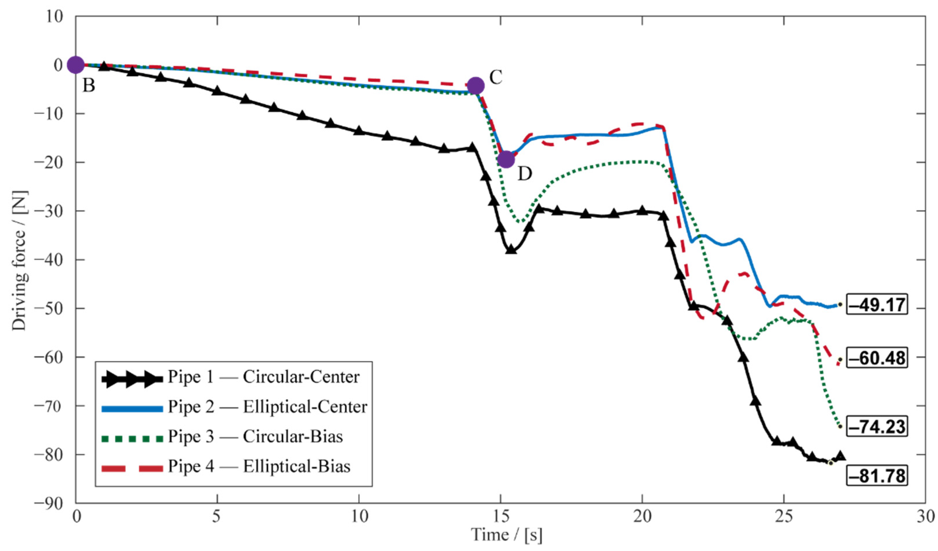
Figure 24. The working conditions for driving force verification are the typical coupling conditions of (
X −2 mm,
Z −2 mm, Roll −1°, Yaw −1°, Pitch −1°). The results show that both the envelope and the maximum value of driving force of the mechanism with the elliptical-helical pipe are optimal, where the elliptical-helical pipe with center loading has 40% reduction compared with the circular-helical pipe with center loading, which verifies the superiority of the elliptical-helical refueling pipe for on-orbit berthing-based refueling.
5. Conclusions
This paper proposes a novel floating docking mechanism for on-orbit refueling during berthing, and the design details are described exhaustively. A probe–drogue configuration is adopted for the proposed mechanism to achieve passive alignment and self-resetting for five DOFs. Two double-winding servo motors are equipped with a redundancy design to increase docking reliability. The proposed mechanism is light, compact, and simple, aiming to achieve a lower driving force. Considering the characteristics of berthing docking, mechanical analysis of the docking process, and the compactness required for on-orbit mechanisms, an elliptical-helical pipe with bias loading is proposed to decrease the requirement of the driving force. The formula for axial stiffness is derived using the energy-based method, and strength checking is derived using the third strength theory.
To verify the validity of the proposed model and method, three types of simulations and experiments were performed: static analysis of the mechanical properties of the refueling pipe, kinematic analysis of the tolerance range of the docking mechanism, and dynamic analysis of the driving force of the docking mechanism. For the static analysis, the relative error of the axial stiffness and maximum stress of the theoretical resolution and simulation are less than 1.2% and 0.6%, respectively, and the relative error of the axial stiffness of the theoretical and experimental result is less than 4.4%, which verifies the accuracy of the formula of axial stiffness. For the kinematic analysis, the results of the simulations and experiments verify the correctness of the estimated tolerance range with values of ±4 mm on two linear misalignments and ±2.5° on three angular misalignments and the self-resetting ability, which meet R1 and R2 in
Section 2. For the dynamic analysis, all trends and values of the contact force under four typical working conditions obtained by the simulations coincide with the experiments, which verifies the validity of the dynamic simulation model. Then, the dynamic simulation model obtains the driving forces of the docking mechanism with four types of pipes (circular-helical or elliptical-helical pipe with center loading or bias loading). Both the envelope and the maximum driving force of the mechanism with the elliptical-helical pipe are superior to those of the circular-helical pipe, which is suitable for the proposed docking mechanism, meeting R3 in
Section 2.


