
Multisatellite Task Allocation and Orbit Planning for Asteroid Terminal Defence


Abstract
:1. Introduction
- (1)
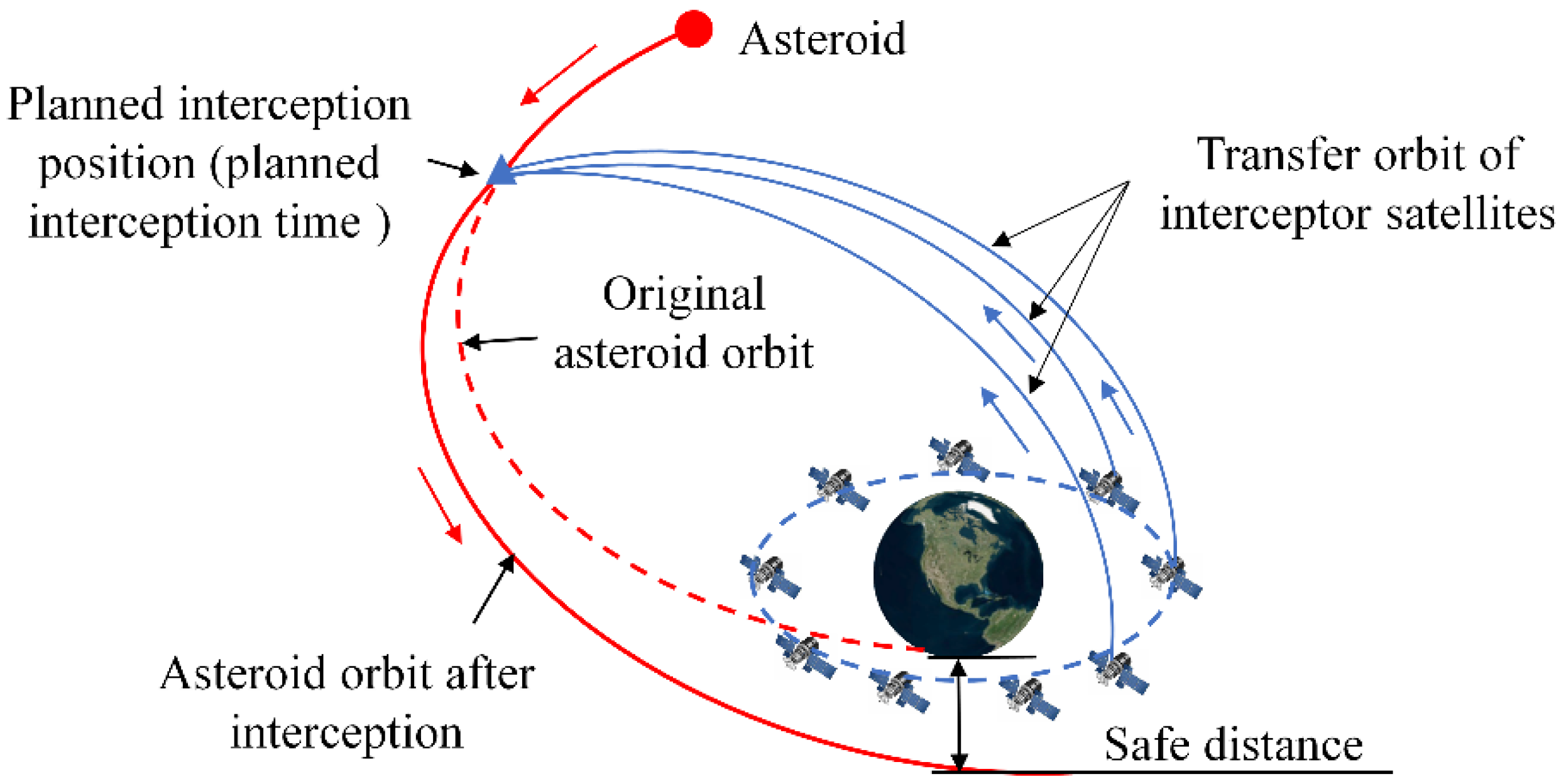
- Multisatellite-based terminal defence strategy for the asteroid that invaded the sphere of the gravitational influence of the Earth is investigated. It can be regarded as a remedial measure after the failure of early defence means and as a method to defend against suddenly discovered/invading asteroids.
- (2)
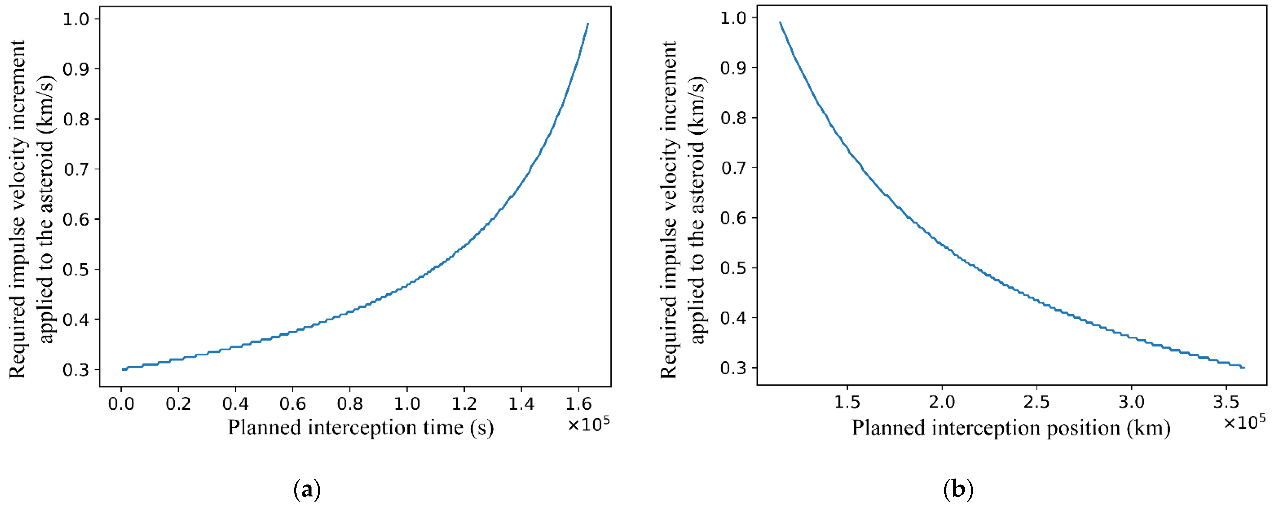
- The effect law of interception positions on the magnitude of the required impulse velocity increment applied to the invading asteroid is disclosed. It can be a reference for defensive interception strategy formulation.
- (3)
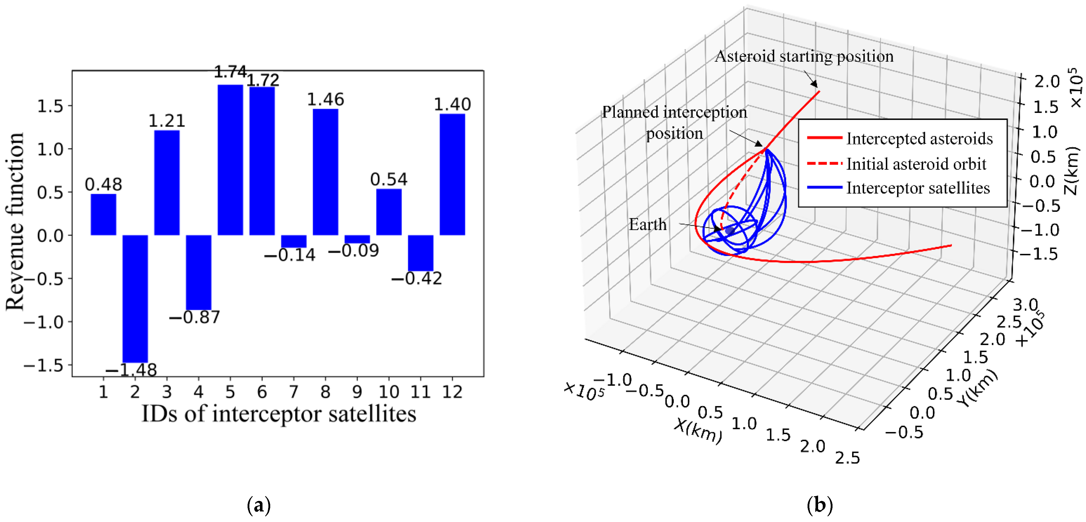
- An improved contract net protocol algorithm considering the Lambert orbital manoeuvre is proposed to realise the coupling of defence task allocation and orbit planning, which can accomplish terminal asteroid defence with multisatellite cooperative interception.
2. Problem Description
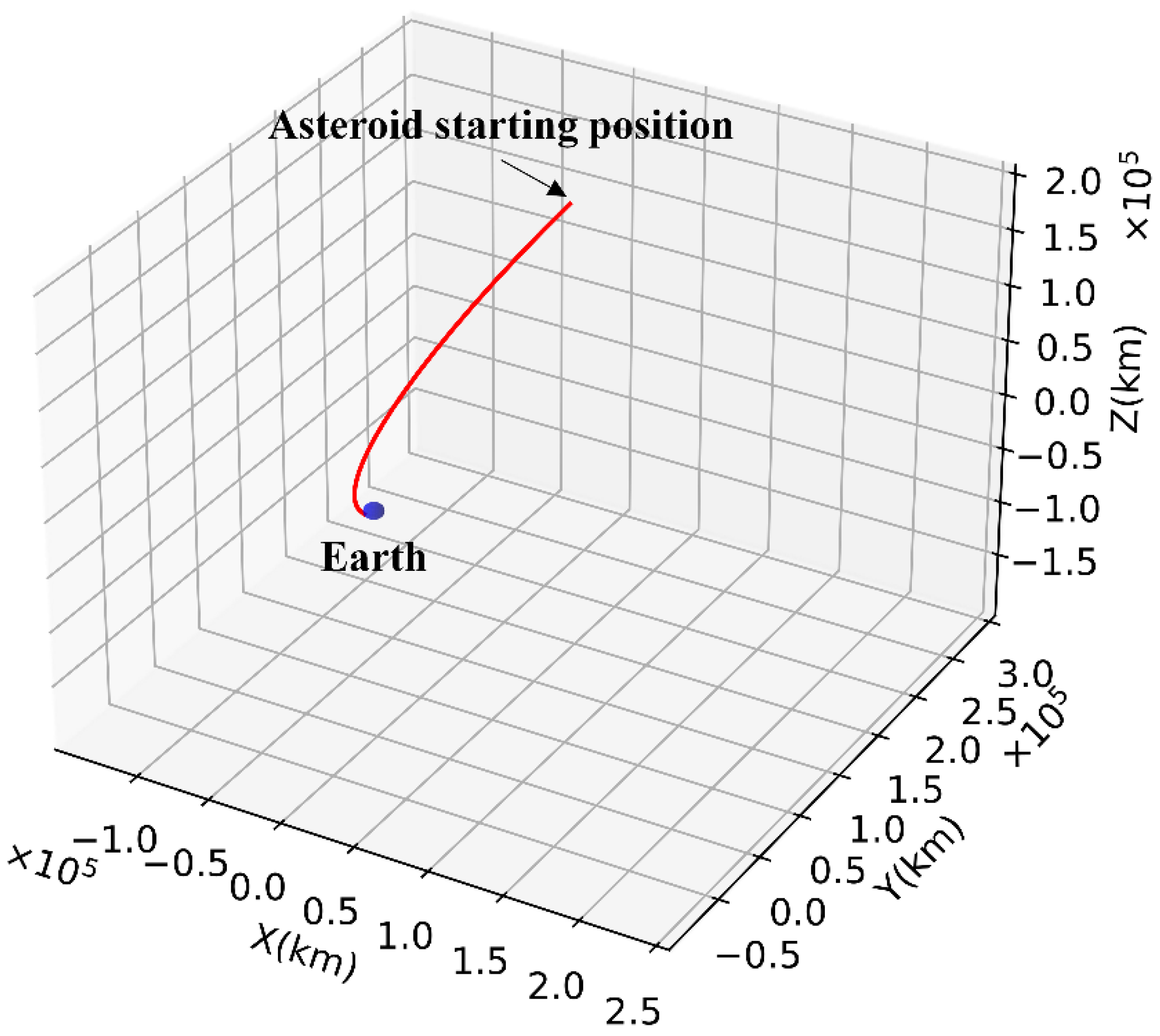
2.1. Terminal Asteroid Defence Scenario Description
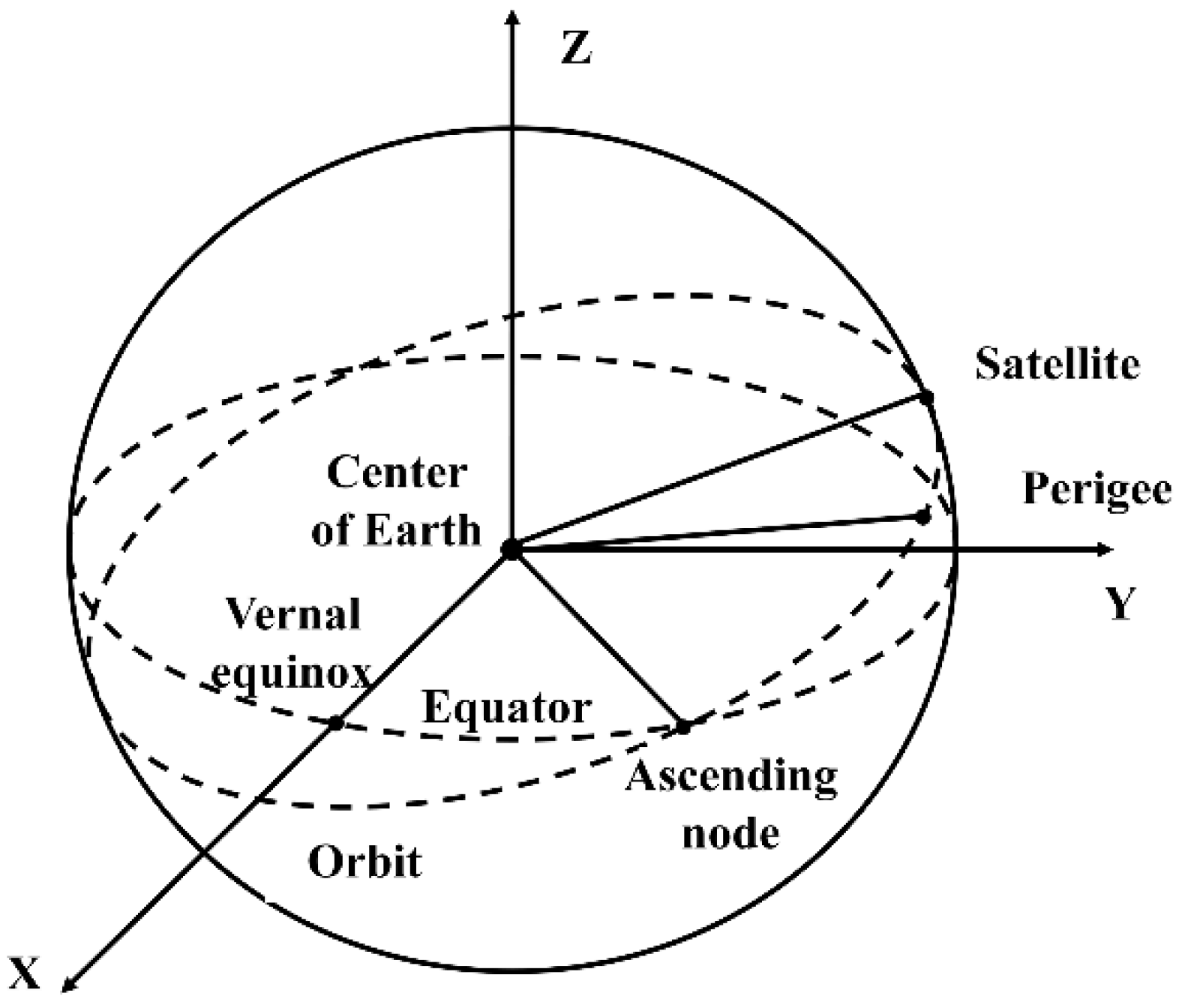
2.2. Coordinate System and Modelling
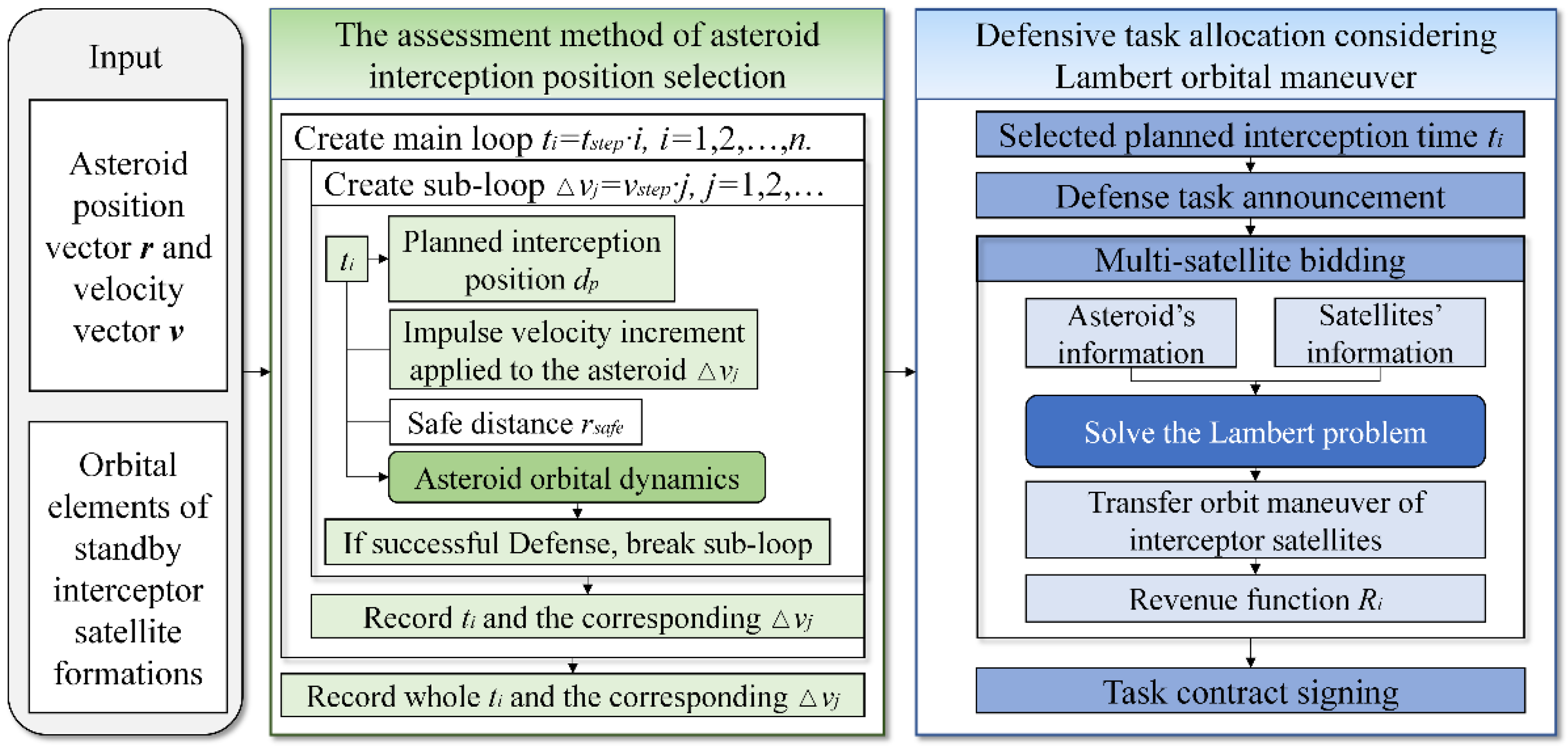
3. Asteroid Interception Position Assessment and Selection
- Step 1:
- Traverse the entire interception time interval with as the time step to obtain n interception times, and . Create a main loop .
- Step 2:
- In the main loop, for each interception time , the corresponding interception position , asteroid position , and velocity are calculated by orbital dynamics theory based on the initial state of the asteroid.
- Step 3:
- Create a subloop, starting from . Apply an impulse manoeuvre to the asteroid with as the step, obtaining the new asteroid velocity, , where the direction of is determined by Equation (7).
- Step 4:
- Based on the asteroid position vector and the new velocity vector, calculate the asteroid orbit, and calculate the minimum distance to the Earth, . If , the defence is successful, record the current , which is the magnitude of the impulse velocity increment required for the defence, and the subloop ends, go to Step 2 to continue the main loop. If , then and return to Step 3 to continue the subloop.
- Step 5:
- Finally, after the end of the main cycle, for each interception time , the corresponding - and - graphs are plotted.
4. Defence Task Allocation Considering the Lambert Orbital Manoeuvre
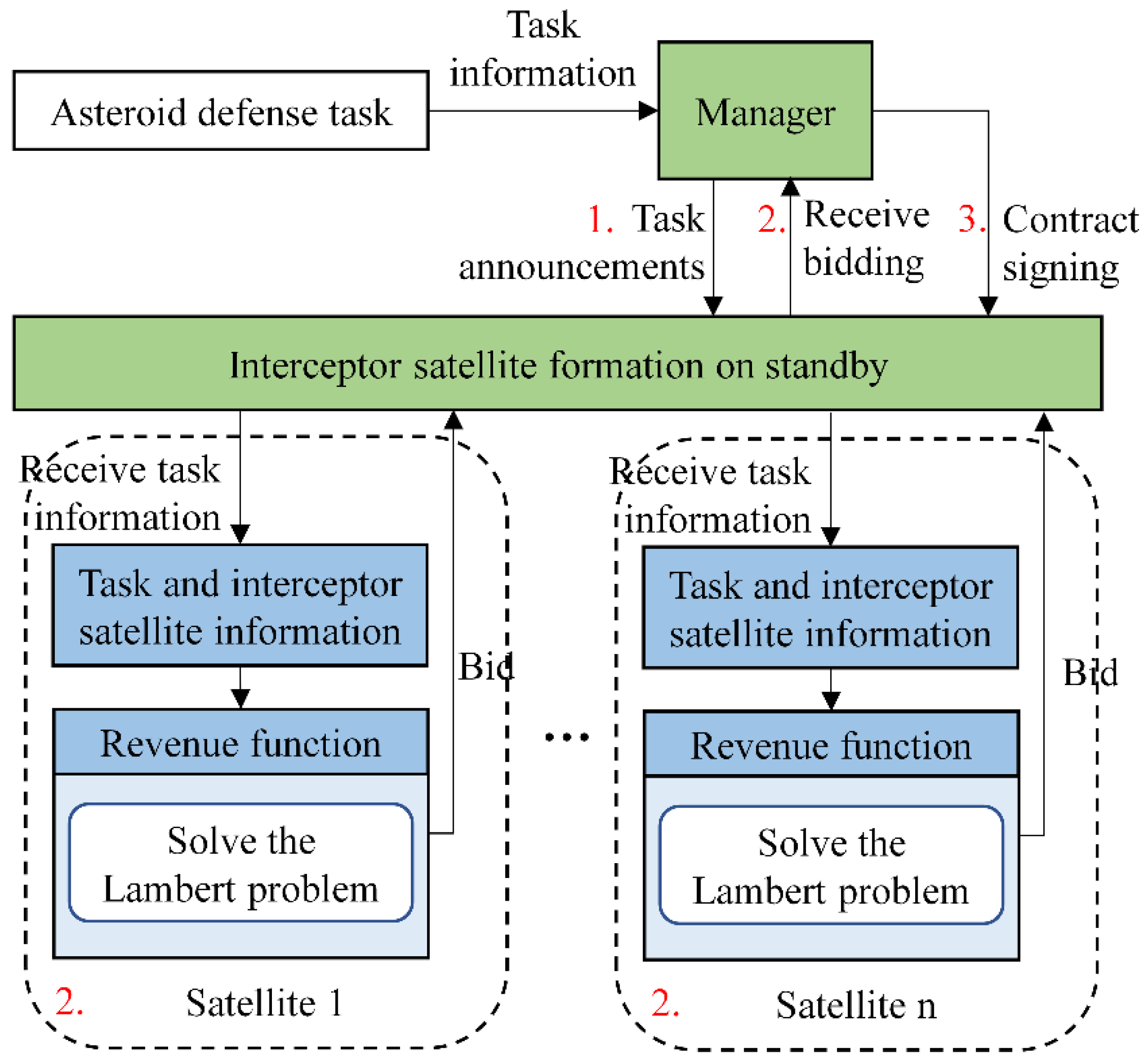
4.1. Contract Net Protocol Algorithm Framework
- (1)
- Task announcement phase.
- (2)
- Bidding phase.
- (3)
- Contract signing phase.
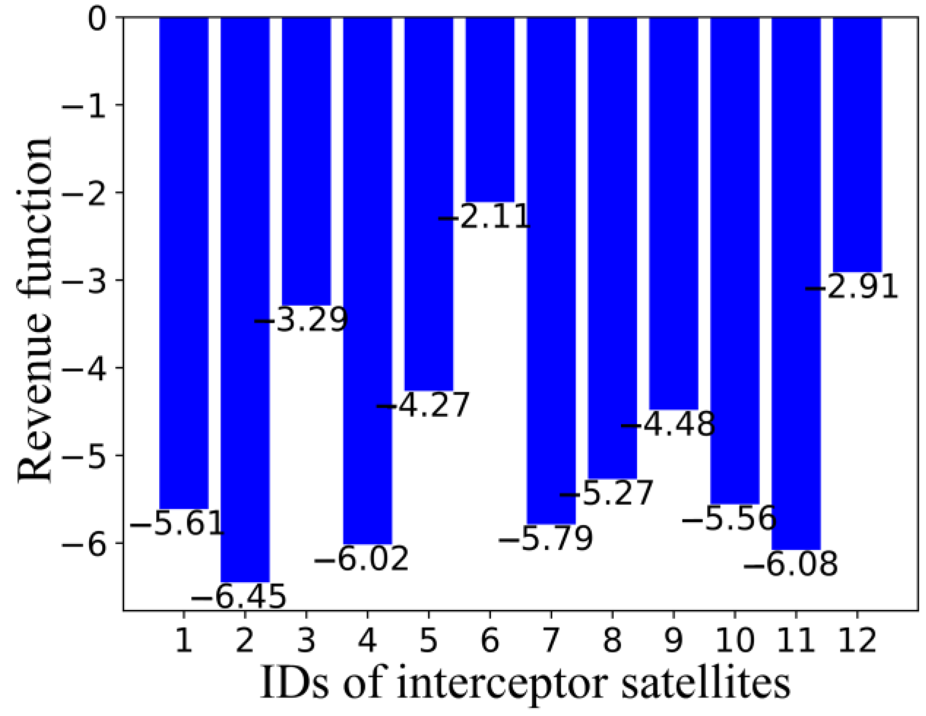
4.2. Revenue Function Construction for the Contract Net Protocol Algorithm
5. Simulations
5.1. Simulation Setup
5.2. Simulation Results
5.2.1. Analysis of Asteroid Interception Opportunity
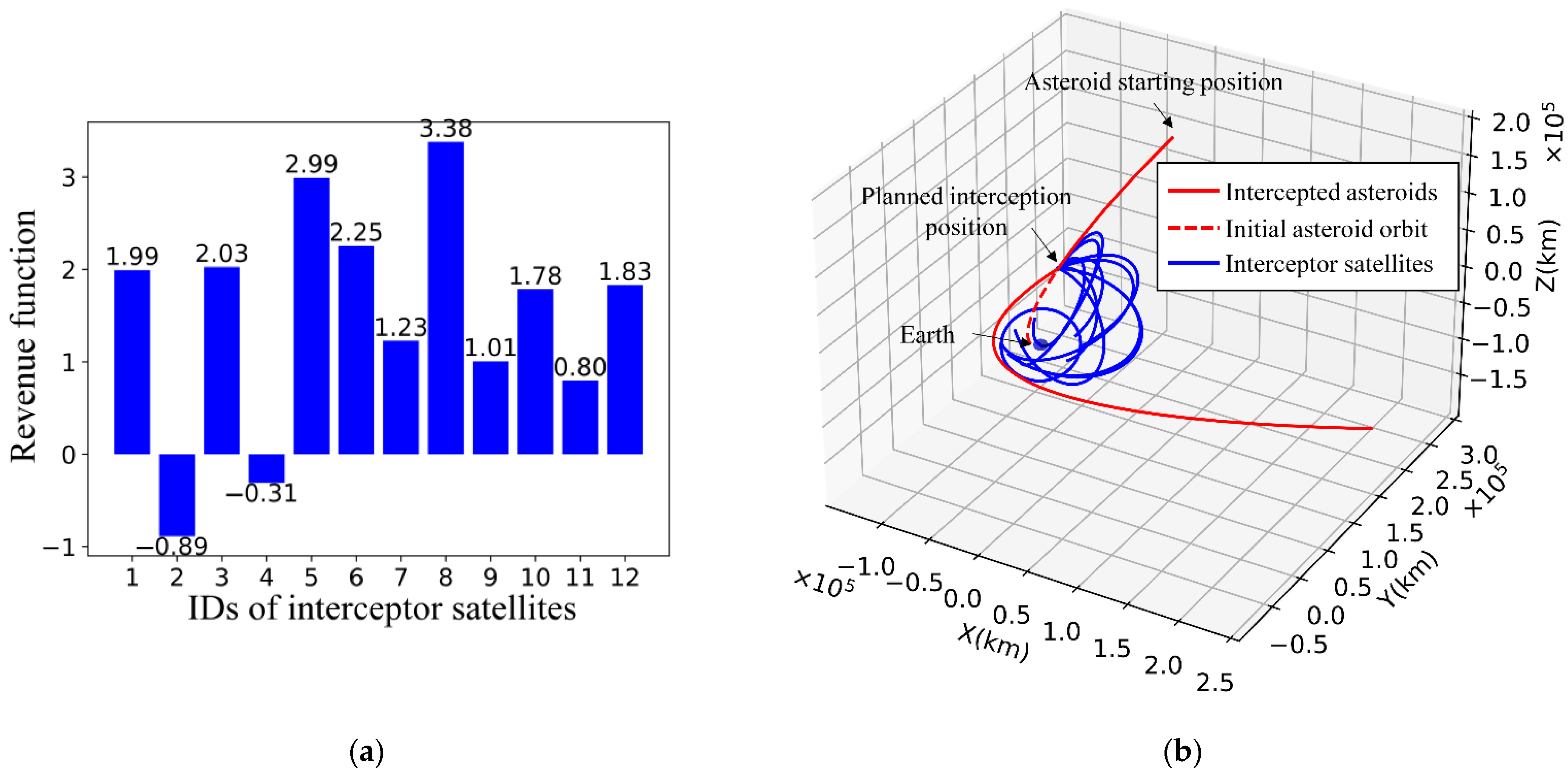
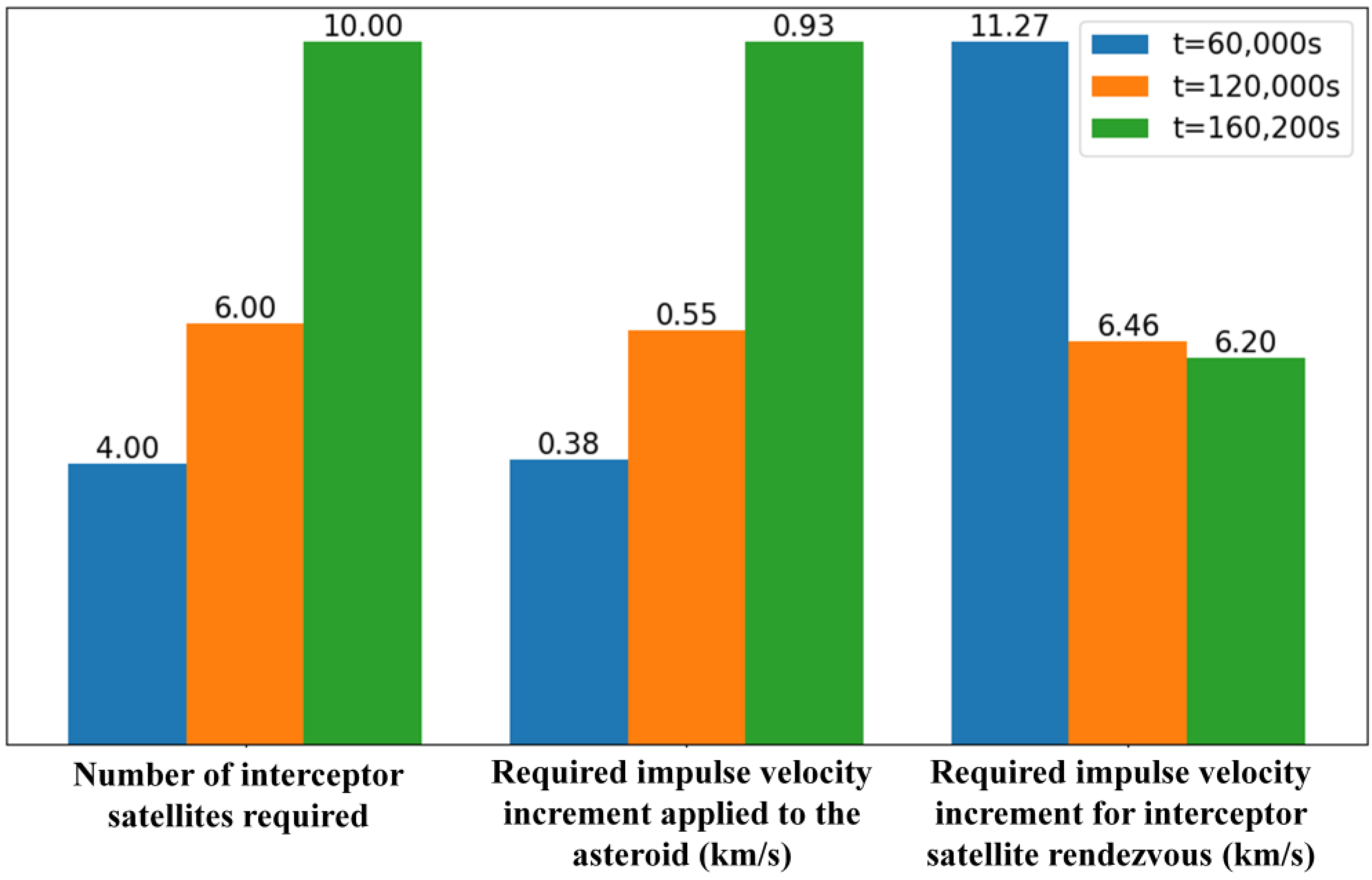
5.2.2. Comparison Simulations of Asteroid Terminal Defence Using the Proposed Technique
- (1)
- Defence task allocation and interception orbit planning when .
- (2)
- Defence task allocation and interception orbit planning when .
- (3)
- Defence task allocation and interception orbit planning when .
5.2.3. Analysis and Discussion
6. Conclusions
Author Contributions
Funding
Institutional Review Board Statement
Informed Consent Statement
Data Availability Statement
Acknowledgments
Conflicts of Interest
References
- Wu, W.R.; Gong, Z.Z.; Tang, Y.H.; Zhang, P.L. Response to risk of near-earth asteroid impact. Strateg. Study CAE 2022, 24, 140–151. [Google Scholar] [CrossRef]
- Silber, E.A.; Boslough, M.; Hocking, W.K.; Gritsevich, M.; Whitaker, R.W. Physics of meteor generated shock waves in the Earth’s atmosphere—A review. Adv. Space Res. 2018, 62, 489–532. [Google Scholar] [CrossRef] [Green Version]
- Chyba, C.F.; Thomas, P.J.; Zahnle, K.J. The 1908 Tunguska explosion: Atmospheric disruption of a stony asteroid. Nature 1993, 361, 40–44. [Google Scholar] [CrossRef]
- Brown, P.G.; Assink, J.D.; Astiz, L.; Blaauw, R.; Boslough, M.B.; Borovička, J.; Brachet, N.; Brown, D.; Campbell-Brown, M.; Ceranna, L.; et al. A 500-kiloton airburst over Chelyabinsk and an enhanced hazard from small impactors. Nature 2013, 503, 238–241. [Google Scholar] [CrossRef]
- Galimov, E.M.; Kolotov, V.P.; Nazarov, M.A.; Kostitsyn, Y.A.; Kubrakova, I.V.; Kononkova, N.N.; Roshchina, I.A.; Alexeev, V.A.; Kashkarov, L.L.; Badyukov, D.D.; et al. Analytical results for the material of the Chelyabinsk meteorite. Geochem. Int. 2013, 51, 522–539. [Google Scholar] [CrossRef]
- Martino, S.; Tancredi, G.; Monteiro, F.; Lazzaro, D.; Rodrigues, T. Monitoring of asteroids in cometary orbits and active asteroids. Planet. Space Sci. 2019, 166, 135–148. [Google Scholar] [CrossRef]
- Wang, Y.; Xu, S.J. Non-equatorial equilibrium points around an asteroid with gravitational orbit-attitude coupling perturbation. Astrodynamics 2020, 4, 1–16. [Google Scholar] [CrossRef]
- Li, X.Y.; Qiao, D.; Barucci, M.A. Analysis of equilibria in the doubly synchronous binary asteroid systems concerned with non-spherical shape. Astrodynamics 2018, 2, 133–146. [Google Scholar] [CrossRef]
- Wei, B.W.; Shang, H.B.; Qiao, D. Hybrid model of gravitational fields around small bodies for efficient trajectory propagation. J. Guid. Control. Dyn. 2020, 43, 232–249. [Google Scholar] [CrossRef]
- Zhang, Y.; Yu, Y.; Baoyin, H.X. Dynamical behavior of flexible net spacecraft for landing on asteroid. Astrodynamics 2021, 5, 249–261. [Google Scholar] [CrossRef]
- Liu, X.W.; Yang, H.W.; Li, S. Collision-free trajectory design for long-distance hopping transfer on asteroid surface using convex optimization. IEEE Trans. Aerosp. Electron. Syst. 2021, 57, 3071–3083. [Google Scholar] [CrossRef]
- Hao, Z.W.; Zhao, Y.; Chen, Y.; Zhang, Q.H. Orbital maneuver strategy design based on piecewise linear optimization for spacecraft soft landing on irregular asteroids. Chin. J. Aeronaut. 2020, 33, 2694–2706. [Google Scholar] [CrossRef]
- Yang, H.W.; Bai, X.L.; Baoyin, H.X. Rapid generation of time-optimal trajectories for asteroid landing via convex optimization. J. Guid. Control. Dyn. 2017, 40, 628–641. [Google Scholar] [CrossRef]
- Yang, H.W.; Li, S.; Bai, X.L. Fast homotopy method for asteroid landing trajectory optimization using approximate initial costates. J. Guid. Control. Dyn. 2019, 42, 585–597. [Google Scholar] [CrossRef]
- Schirru, L.; Pisanu, T.; Podda, A. The ad hoc back-end of the BIRALET radar to measure slant-range and Doppler shift of resident space objects. Electronics 2021, 10, 577. [Google Scholar] [CrossRef]
- Ionescu, L.; Rusu-Casandra, A.; Bira, C.; Tatomirescu, A.; Tramandan, I.; Scagnoli, R.; Istriteanu, D.; Popa, A.E. Development of the Romanian radar sensor for space surveillance and tracking activities. Sensors 2022, 22, 3546. [Google Scholar] [CrossRef]
- Ender, J.; Leushacke, L.; Brenner, L.; Wilden, H. Radar Techniques for Space Situational Awareness. In Proceedings of the IEEE International Radar Symposium (IRS), Leipzig, Germany, 7–9 September 2011. [Google Scholar]
- European Space Surveillance and Tracking Program. Available online: https://www.eusst.eu/ (accessed on 30 June 2022).
- Yu, Z.T.; Shang, H.B.; Wei, B.W. Accessibility assessment and trajectory design for multiple Near-Earth-asteroids exploration using stand-alone CubeSats. Aerosp. Sci. Technol. 2021, 118, 106944. [Google Scholar] [CrossRef]
- Cheng, A.F.; Atchison, J.; Kantsiper, B.; Rivkin, A.S.; Stickle, A.; Reed, C.; Galvez, A.; Carnelli, I.; Michel, P.; Ulamecd, S. Asteroid impact and deflection assessment mission. Acta Astronaut. 2015, 115, 262–269. [Google Scholar] [CrossRef] [Green Version]
- Wagner, S.; Wie, B.; Barbee, B.W. Target selection for a hypervelocity asteroid intercept vehicle flight validation mission. Acta Astronaut. 2015, 107, 247–261. [Google Scholar] [CrossRef]
- Wie, B.; Zimmerman, B.; Lyzhoft, J.; Vardaxia, G. Planetary defense mission concepts for disrupting/pulverizing hazardous asteroids with short warning time. Astrodynamics 2017, 1, 3–21. [Google Scholar] [CrossRef]
- Lubin, P.; Hughes, G.B.; Eskenazi, M.; Kosmo, K.; Johansson, I.S.; Griswold, J.; Pryor, M.; O’Neill, H.; Meinhold, P.; Suen, J.; et al. Directed energy missions for planetary defense. Adv. Space Res. 2016, 58, 1093–1116. [Google Scholar] [CrossRef] [Green Version]
- Tsuda, Y.; Takeuchi, H.; Ogawa, N.; One, G.; Kikuchi, S.; Oki, Y.; Ishiguro, M.; Kuroda, D.; Urakawa, S.; Okumura, S.; et al. Rendezvous to asteroid with highly uncertain ephemeris: Hayabusa2′s Ryugu-approach operation result. Astrodynamics 2020, 4, 137–147. [Google Scholar] [CrossRef]
- Yue, Y.X.; Shan, H.L.; Zhou, Z.W.; Wang, X.H. A fast calculation method for asteroid exploration window based on optimal and sub-optimal two-impulse transfer orbits. Acta Astronaut. 2021, 186, 171–182. [Google Scholar] [CrossRef]
- Mathias, D.L.; Wheeler, L.F.; Dotson, J.L. A probabilistic asteroid impact risk model: Assessment of sub-300 m impacts. Icarus 2017, 289, 106–119. [Google Scholar] [CrossRef]
- Zhang, F.; Xu, B.; Circi, C.; Zhang, L. Rotational and translational considerations in kinetic impact deflection of potentially hazardous asteroids. Adv. Space Res. 2017, 59, 1921–1935. [Google Scholar] [CrossRef]
- Peak, S.W.; Weck, O.; Hoffman, J.; Binzel, R.; Miller, D. Optimization and decision-making framework for multi-staged asteroid deflection campaigns under epistemic uncertainties. Acta Astronaut. 2020, 167, 23–41. [Google Scholar] [CrossRef]
- Sankaran, K.; Griffith, S.A.; Thompson, N.C.; Lochridge, M.D.; O’Kins, A.S. A parallelized genetic algorithm to evaluate asteroid impact missions using electric propulsion. Aerospace 2022, 9, 116. [Google Scholar] [CrossRef]
- Kim, G.; Jeon, S.; Kee, C.; No, T.S.; Kwon, K.; Choi, S. GPS satellite state vector determination in ECI coordinate system using the civil navigation message. J. Navig. 2014, 67, 1–16. [Google Scholar] [CrossRef]
- Yang, B.; Liu, P.X.; Feng, J.L.; Li, S. Two-stage pursuit strategy for incomplete-information impulsive space pursuit-evasion mission using reinforcement learning. Aerospace 2021, 8, 299. [Google Scholar] [CrossRef]


| Orbital Elements | Symbol | Value | Unit | Remarks |
|---|---|---|---|---|
| Semi-major axis | 38,000 | km | denotes the orbital plane serial number, denotes the satellite serial number within the orbital plane | |
| Eccentricity | 0 | - | ||
| Orbital inclination | 53 | deg | ||
| Argument of periapsis | 0 | deg | ||
| Right ascension of ascending node | deg | |||
| True anomaly | deg |
| Asteroid State | Symbol | Value | Unit |
|---|---|---|---|
| Position vector | [−68,662.408, 351,593.459, 34,040.410] | km | |
| Velocity vector | [0.01951218, −1.09871708, −0.10637507] | km/s | |
| Mass | 109 | kg |
Publisher’s Note: MDPI stays neutral with regard to jurisdictional claims in published maps and institutional affiliations. |
© 2022 by the authors. Licensee MDPI, Basel, Switzerland. This article is an open access article distributed under the terms and conditions of the Creative Commons Attribution (CC BY) license (https://creativecommons.org/licenses/by/4.0/).
Share and Cite
Luo, Y.; Jiang, X.; Zhong, S.; Ji, Y.; Sun, G. Multisatellite Task Allocation and Orbit Planning for Asteroid Terminal Defence. Aerospace 2022, 9, 364. https://doi.org/10.3390/aerospace9070364
Luo Y, Jiang X, Zhong S, Ji Y, Sun G. Multisatellite Task Allocation and Orbit Planning for Asteroid Terminal Defence. Aerospace. 2022; 9(7):364. https://doi.org/10.3390/aerospace9070364
Chicago/Turabian StyleLuo, Yuelong, Xiuqiang Jiang, Suchuan Zhong, Yuandong Ji, and Guohao Sun. 2022. "Multisatellite Task Allocation and Orbit Planning for Asteroid Terminal Defence" Aerospace 9, no. 7: 364. https://doi.org/10.3390/aerospace9070364