1. Introduction
The evolution of the air transportation system is nowadays experiencing a turning point that will lead to the advent of a completely new scenario in the next decade. Electrification of propulsion, Urban Air Mobility (UAM), suburban air shuttles, and alternative fuels are some of the factors that are inducing a change of paradigm for civil aviation. The effect on society of these ground-breaking solutions is amplified by the enduring expansion of urban areas around airports and the constant increase in air traffic in terms of daily movements and passengers (for additional information and details see Knobloch et al. [
1]). In such a rapidly evolving context, sustainability can be guaranteed only introducing new approaches to the management of the air transportation system, capable of satisfying market requests and, at the same time, preserving the health and the quality of life of citizens. The European community has sponsored several research projects over the last twenty years to develop disruptive technologies and operational procedures to lower the impact on the community of the chemical and acoustic emissions related to civil aviation.
A standard trajectory optimisation is aimed at calculating the best flight path through the minimisation (or maximisation) of a performance index that can deal with noise reduction (in a specific point or in a certain area), fuel consumption or the total cost [
2]. The growth of computational resources, together with the development of sophisticated multiobjective optimisation algorithms have made it possible to deal with the design of the trajectories as a vector minimisation problem (a valuable review of Multi-Objective Trajectory Optimisation techniques for transport aircraft flight operations can be fund in Gardi et al. [
3]), so that multiple environmental factors can be minimised at the same time [
4]. When the main focus is on noise reduction, the resulting flight path can be named a noise abatement procedure (NAP). NAPs can involve, in order to avoid overflight of populated areas, preferential routings [
5] to cope with the well-being of populations living near airports. The NAP design for airport noise mitigation is usually carried out by airlines [
6] under the guidance of the International Civil Aviation Organization (ICAO) and regulatory entities such as the Federal Aviation Administration (FAA). Notwithstanding, over the past decades, universities and research centres have also been involved in the design of environmentally friendly airport procedures: indeed, this activity provides the possibility of developing sophisticated flight simulation tools involving flight dynamics and control, multilevel computational aeroacoustics techniques together with numerical optimisation strategies [
7,
8,
9,
10,
11]. To date, one of the most challenging research topics related to the design of low environmental impact trajectories is the adaptation of the NAP design techniques to the new aircraft concepts, such as the Blended Wing Body (BWB) configuration: for such disruptive layouts the designer cannot rely on past experience; thus, a viable strategy appears to be metamodelling the BWB shielding effect [
12,
13], with the aim of exploiting the existing well-assessed noise estimation tools for the prediction of future airport scenarios.
The work presented in this paper is different from traditional trajectory optimisations, and it can be considered as an evolution of the approach first introduced during the SEFA projects (Sound Engineering For Aircraft, FP6, 2004–2007 [
14,
15,
16]) to assess the perceptive qualities of the noise produced by a civil aircraft, and subsequently evolved to an airport scenario (i.e., a prescribed sequence of takeoff and landing procedures) during COSMA (community noise solutions to minimise aircraft noise annoyance, FP7, 2009–2012 [
17,
18]). Here, the sound quality assessment is applied in the multiobjective context adopted in the ANIMA project (Aviation Noise Impact Management through Novel Approaches, H2020, 2017–2021, [
1,
19]) as a criterion to select the least annoying procedure from the Pareto set of a two-objective optimisation. The objective functions used are indirect measures of the number of citizens affected by a potentially harmful noise level, and of the amount of greenhouse gases injected in the atmosphere.
Specifically, this work aims at exploring multiple noise descriptors for the design of low-noise flight paths. Indeed, the purpose of the analysis presented here is to simultaneously minimise both the chemical and the acoustic emissions: the case studies concern the takeoff and the approach procedures of single- and twin-aisle aircraft, representative of aeroplane classes used for most of the international commercial routes. Since the Multi Objective Optimisation (MOP) solution is composed of a set of non-dominated points, the sound quality assessment is applied to select the optimal trajectories. The aircraft operations have been optimised within the in-house Multidisciplinary Conceptual Robust Design Optimisation (MCRDO) framework FRIDA (Framework for Innovative Design in Aeronautics [
12,
15,
16,
18,
20,
21,
22]). The two objectives to be minimised are the Sound Exposure Level (SEL) 60 dBA contour area and the amount of fuel burnt during the entire airport operation. The decision making criterion makes use of a third objective function, built based on the sound-quality assessment: the latter is formalised as the
norm in the vector space defined by the difference between the noise produced by the aircraft and a weakly annoying target sound (the interested reader can find useful information on the target sound definition in [
18]). It is worth highlighting that
norms of different orders can be used to build objectives that focus on local and distributed differences: this behaviour has been investigated concerning benchmark problems [
16], and it can be demonstrated that it can be exploited when the effect of tonal components is explicitly available. The constrained optimisation problem is solved within FRIDA by using the Deterministic Particle Swarm Optimisation (DPSO) method, a gradient-free global technique introduced by Kennedy and Russel [
23], in its original deterministic implementation [
24,
25]. All the numerical results are presented in terms of approximated Pareto frontiers for takeoff and landing conditions for both the single- and twin-aisle aircraft.
The paper is organised as follows.
Section 2 provides details on the optimisation problem setup, including the definition of the two objectives functions. The main characteristics of both the single- and twin-aisle aircraft are reported in
Section 3. In
Section 4, the optimisation results are presented, and the criteria for the sound-quality-based decision making are reported in
Section 5 with the final designer choices. Finally,
Section 6 presents some concluding remarks.
2. Optimisation Problem Setup
A Generic Constrained Multiobjective Optimisation Problem (MOP) is formalised as
where
is the
k-th objective function (with
being the vector containing the
N design variables), and
and
are the inequality constraints and the equality constraints, respectively. The solution of the above problem consists of the set of non-dominated solutions that forms the Pareto frontier.
In the present multiobjective approach, the two merit functions are related to acoustic and chemical emissions. The acoustic descriptor used here is the Sound Exposure Level (SEL) which represents the most suitable strategy for comparing airport procedures of different durations. Here, the objective function to be minimised is chosen to be a measure of the number of citizens affected by a noise level above a certain threshold. More specifically,
is chosen as the area bounded by the SEL 60 dBA contour, formalised as
where
is the area surrounding the airport where SEL is greater or equal to 60 dBA, with
and
being the reference spatial coordinates of the noise map. The objective function related to the chemical emission is simply the amount of fuel burnt during the manoeuvre,
where
is the time that the aircraft takes to reach an altitude of 10,000 ft,
T is the required thrust and
c is the specific fuel consumption, here modelled as a function of the true air speed (TAS).
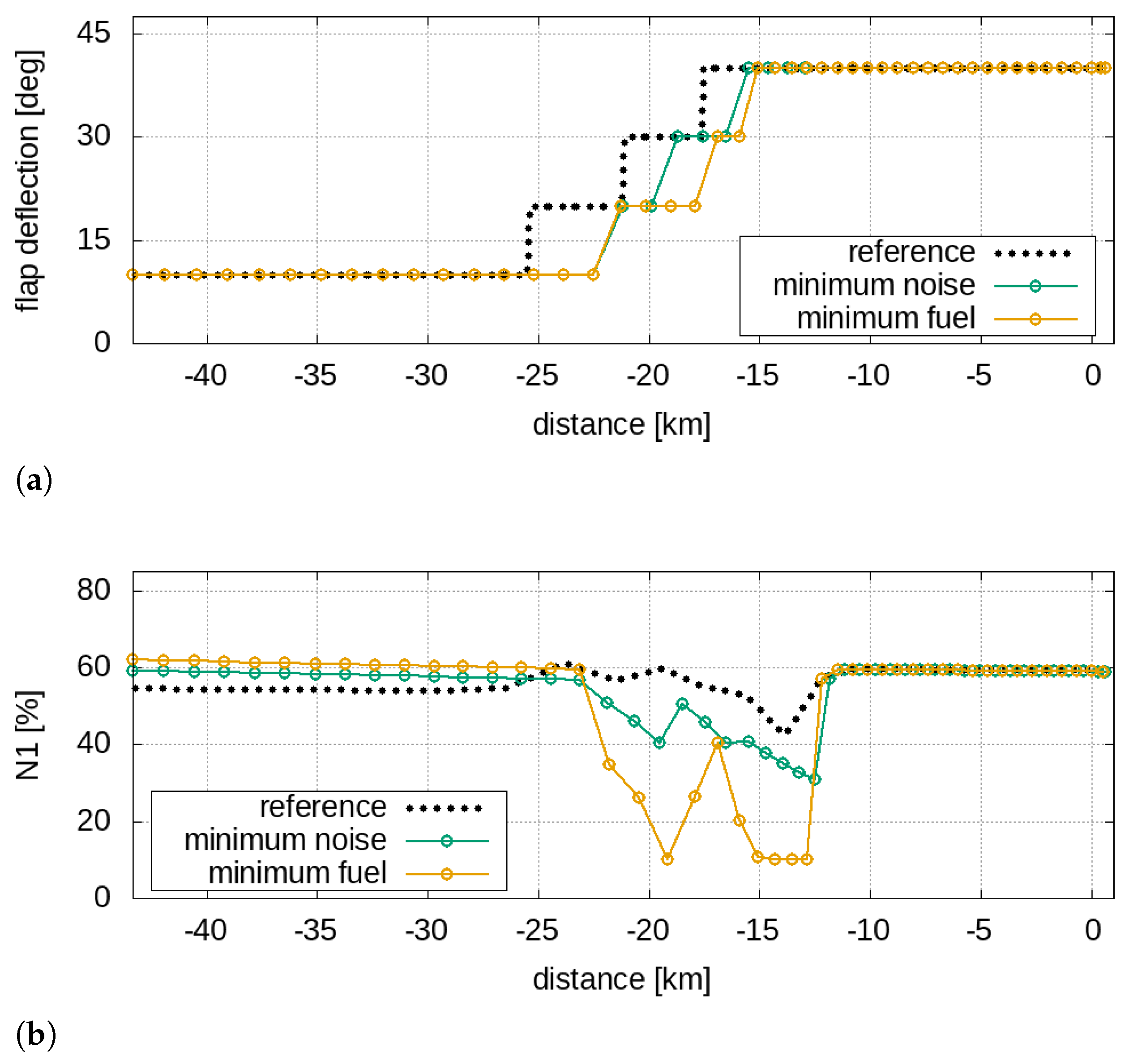
With the aim of ensuring the simulation of a realistic operation, suitable constraints were imposed. First of all, the high-lift devices deployment combined with the angle of attack must ensure a vertical equilibrium, preventing the stall at the
p-th trajectory sample. Thus, the following constraint is imposed
where
is the stall angle. Furthermore, since N1 (the rotational velocity of the low-pressure spool) must not exceed the overspeed in takeoff and must not fall below the idle setting in the approach (
T and
A indicate the takeoff and the approach procedures), the following constraints are also used
where the subscripts
and
stand for overspeed and idle, respectively. To avoid structural failures, the following constraints, which account for the normal load factor
n variation, are imposed
where
and
are the positive and negative limit normal load factor. Equations (
4)–(
7) are calculated at each
p-th sample of the trajectory. In addition, considering the
q-th trajectory segment the following constraint was introduced
to account for the maximum absolute value of the ramp angle over the
Q trajectory segments. Finally, the maximum change in slope
between two consecutive trajectory segments was imposed as
where
, to ensure passenger comfort.
It is important to underline that the correct estimation of
requires the use of suitable aeroacoustic models: indeed, the prediction of the noise at a prescribed location requires both the modelling of the relevant physical phenomena involved in the sound generation and propagation mechanisms. Within the optimisation context, the identification of a proper trade-off between accuracy and computational cost is a crucial aspect: thus, well-assessed semi-empirical models were used here, capable of predicting the aircraft noise spectra at specified location (for useful details, see
Appendix A). In addition, it is worth noting that the deep interplay between aeroacoustics and flight mechanics makes a correct description of the aircraft dynamics and its operating conditions mandatory. Specifically:
The airframe noise during the airport operations is also linked to the deployment of the high lift devices;
Due to the strong directivity of some acoustic sources, the attitude of the aircraft influences the spectrum that reaches a listener;
The noise emitted by the main sources related to the propulsion system (fan, compressor, turbine, buzz-saw and jet) depends on the engine’s settings in terms of N1 and N2, which depends on the required thrust;
The relative speed and the distance between the aircraft and the listener influence the spectrum of the received signal through the Doppler effect and the atmospheric absorption.
Therefore, a detailed description of the aircraft flight mechanics makes it possible to provide an adequate estimate of the noise emissions. Interestingly, since also depends on the required thrust, the two objective functions are intrinsically connected.
3. Case Studies
The case studies involve both a single- and a twin-aisle aircraft, representative of aeroplane classes used for most of the international commercial routes: the first one for short- and medium-haul flights, and the second for medium- to long-haul ones. The aircraft characteristics are reported in
Table 1.
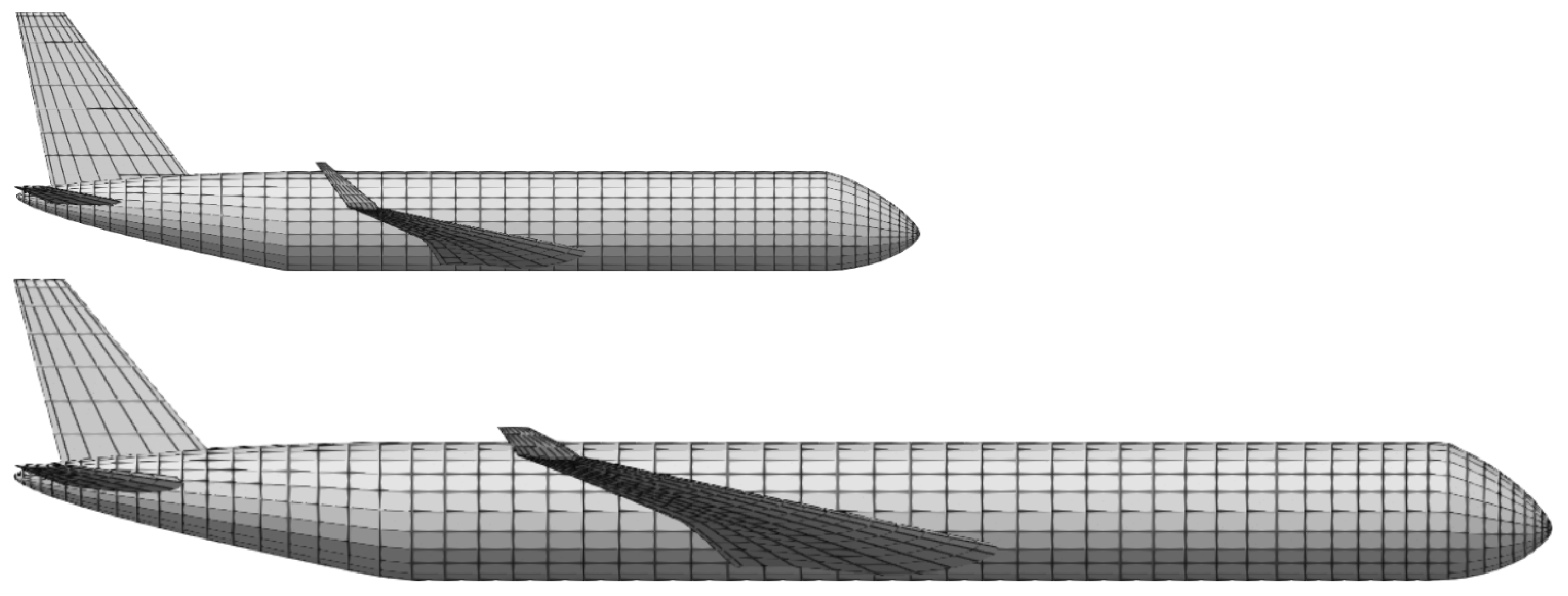
The framework FRIDA builds the aircraft geometrical model, performing a complete analysis for the estimate of aerodynamic and the structural properties. In
Figure 1 are presented the pictorial representations of the models built within FRIDA related to the single- and the twin-aisle aircraft.
All the data coming from the analysis modules are collected and passed to the FRIDA flight simulation environment. With the aim of reducing the computational effort, suitable corrections are applied to the aerodynamic and inertial data to account for the specific flight conditions: by doing this, the airport manoeuvres can be calculated with the expense of a single aircraft analysis, maintaining an accuracy more than acceptable.
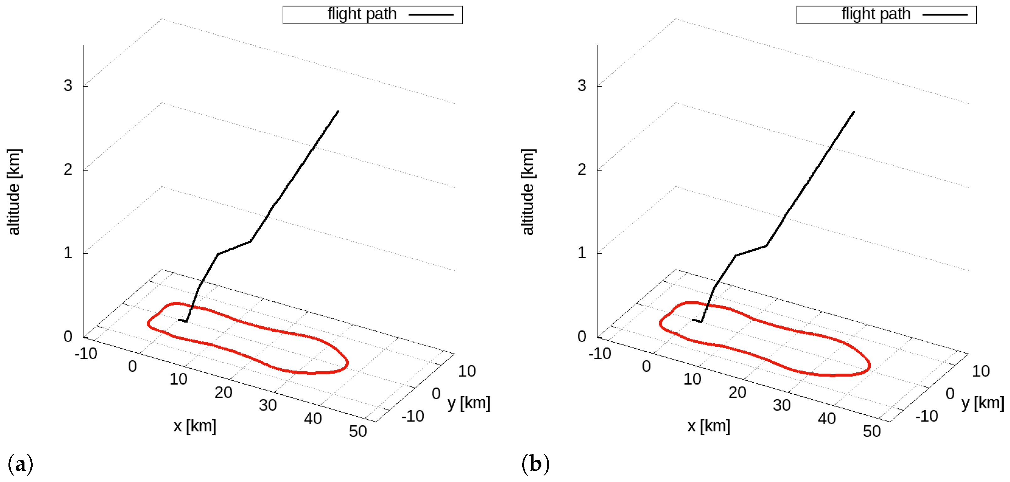
In this work, both takeoff and landing procedures are optimised. Specifically, the reference takeoff manoeuvres are modelled starting from the ICAO procedures for aircraft compatible with the test cases analysed. The trajectories consist of five segments (six input nodes), starting from the brake release up to a distance related to an altitude equal to 10.000 ft (about 35 km from the runway for both the aircraft). The trajectory description is built starting from nodal variables (geometric and kinematic), reported in
Table 2.
The initial aircraft masses for the takeoff phase were set approximately equal to 77 tons for the single-aisle aircraft and 217 tons for the twin-aisle, corresponding to 98% and 95% of the MTOW, respectively. In
Figure 2 are depicted the reference takeoff trajectories for the single- and the twin-aisle aircraft with the 60 dBA isolevel.
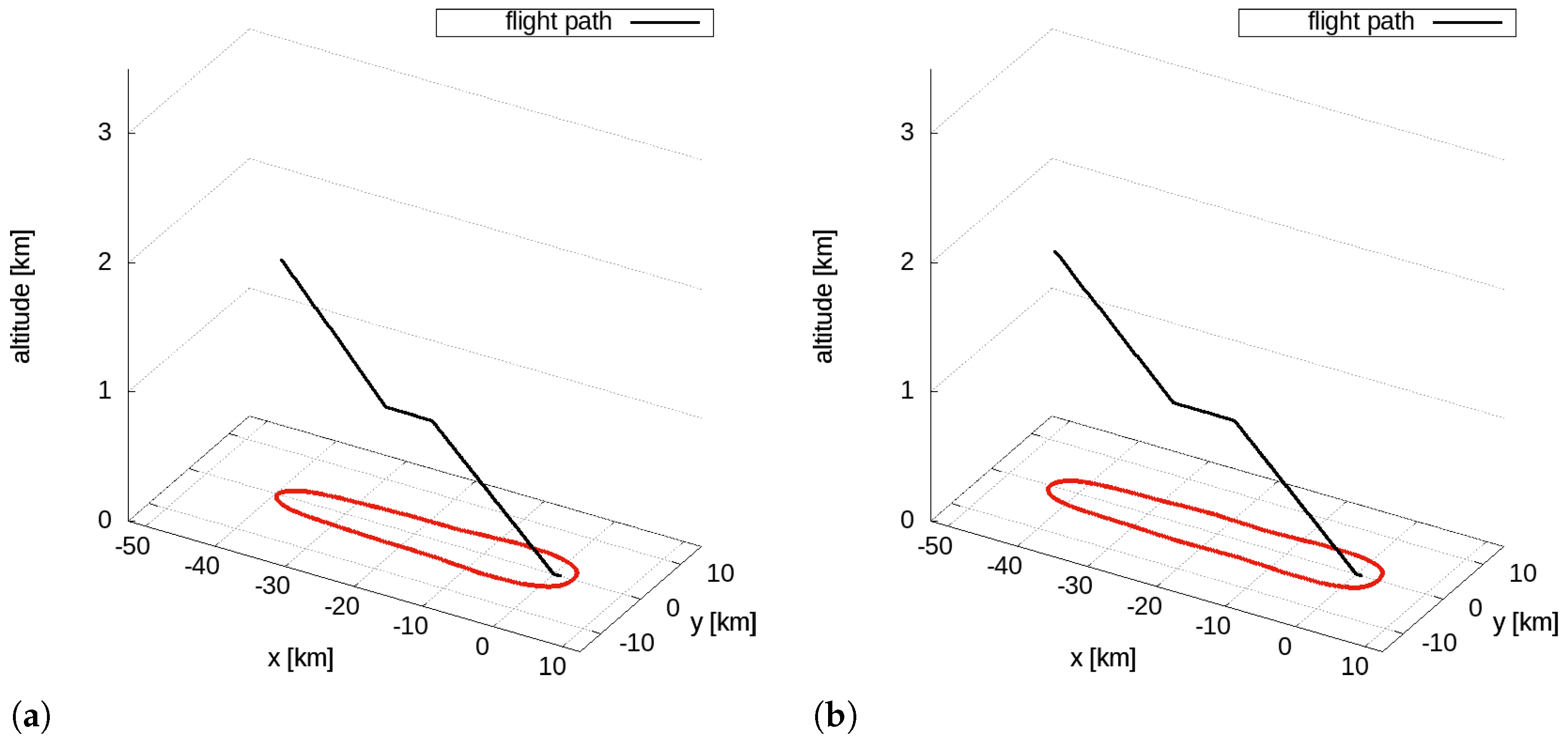
The reference approach phases are modelled based on the standard ICAO procedures for two aircrafts compatible with the test cases chosen. The trajectory consists of six segments (seven input nodes), starting at about 40 km from the airport and ending at the touchdown point on the runway. The geometric and the kinematic variables of the nodes are reported in
Table 3.
The initial masses for the approach phase for the single- and twin-aisle aircraft are about 58 tons and 157 tons, respectively, corresponding to 135% of the OEW for the single-aisle aircraft and 129% of the OEW for the twin-aisle. The reference approach trajectories for the single- and the twin-aisle aircraft with the 60 dBA isolevel are depicted in
Figure 3.
5. Sound-Quality-Based Decision Making
It is known that the single-objective optimisation problem leads to the identification of a unique design space point corresponding to the minimum of the objective function, which can be considered by the designer as the optimal solution. In contrast, the multiobjective problem solution consists of a set of non-dominated optimal solutions that constitute the Pareto frontier; therefore, from the designer’s point of view the choice of the optimum among the Pareto front plays a key role. It is worth noting that the Pareto front could be a mathematically consistent but technically irrelevant entity, and this occur when the non-dominated solutions are close to each other both in the domain and in the codomain: in this case, the designer can consider the whole set of optimal solutions as a unique optimum. On the other hand, when the solutions are far both in the domain and in the codomain (or even close in the domain and far away in the codomain), the need to establish a criterion for decision making has a paramount relevance.
In the view of sustainable airport scenarios, a viable strategy is including the quality of the noise within the decision making process: this can be done by comparing the noise produced by the aircraft and a weakly annoying target sound. Such an approach is based on the measure of the matching of the noise emitted by the operation under analysis with a previously defined weakly annoying sound. The noise reaching the virtual microphone during a flight operation is characterised by a specific spectrogram, which provides the amplitude of the noise event in the time-frequency domain. Thus, let us consider the vector space defined by the difference between the spectrogram
related to the current flight path and the spectrogram
related to the target sound
The norm of
in the
space can be used as a metric to quantify the similarity of the actual spectrogram with respect to the target one. Accordingly, the sound-matching index
can be formalised as follows
where
and
. The target sounds used in this work were synthesised on the basis of psychometric test campaigns performed within the projects SEFA and COSMA [
14,
17]. It is worth noting that the choice of
p can be exploited by the designer to focus the metric on tonal broadband or tonal component dissimilarities (low and high values of
p, respectively); indeed, low values of
p enhance the contribution of distributed differences and high values of
p emphasise the local ones. Optimisation problems involving
have been successfully used in both the aircraft conceptual design and single-point low-noise flight path optimisation [
16,
22].
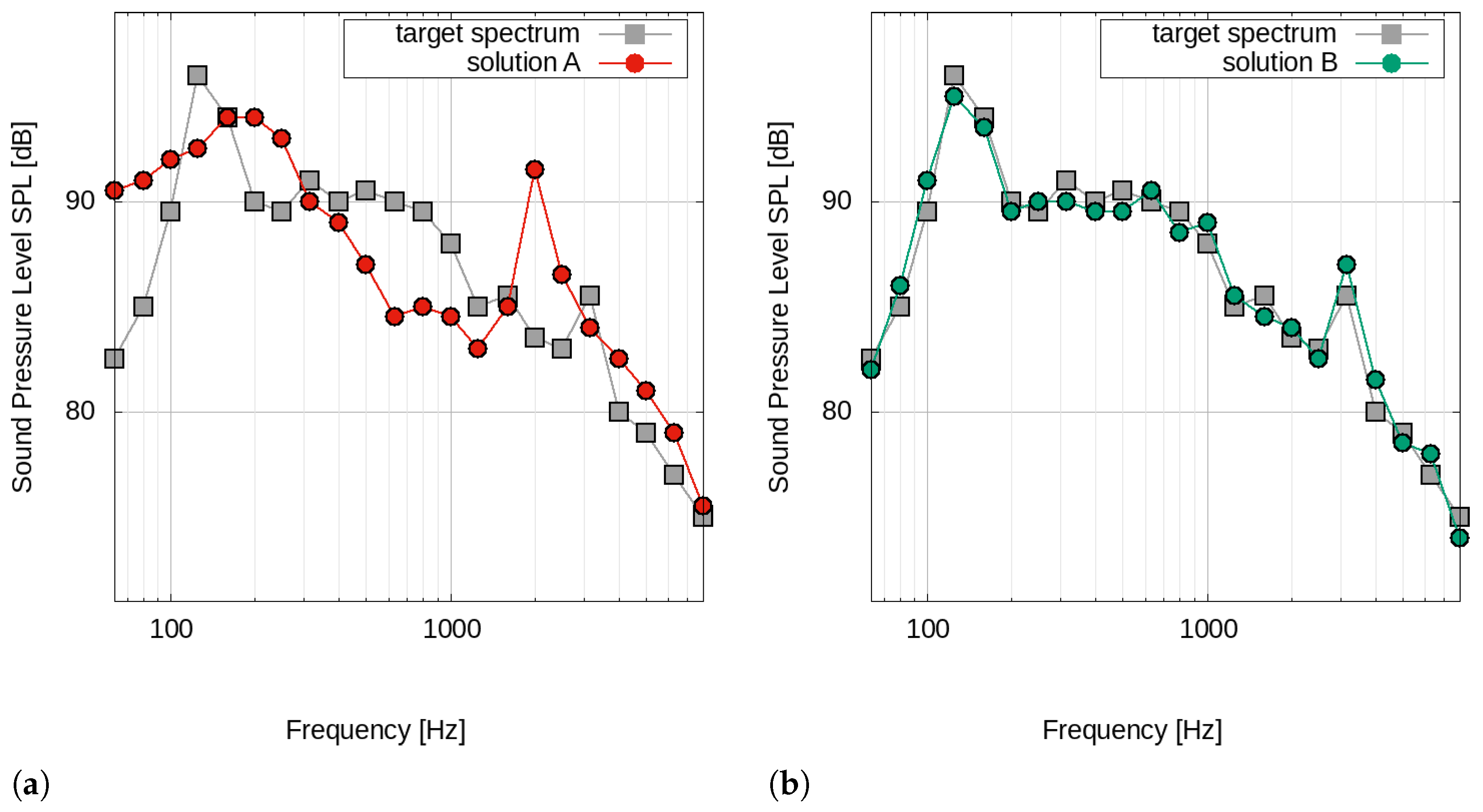
Figure 16 shows a pictorial representation of the sound-matching concept, and depicts the spectral comparison of two signals (solution A and B) with respect to a target spectrum for a certain time instant.
The spectral properties related to solution A of
Figure 16a are quite different with respect to the target spectrum: in this case, Equation (
12) (in this example with
p = 2) returns a high value of
. In contrast, solution B (see
Figure 16b) turns out to have frequency characteristics similar to the target spectrum; therefore, the
value is low. In the case of an entire manoeuvre simulation, the
value is simply a cumulative value over all the analysed time instants.
Pareto Solution Analysis and Designer’s Choice
Let us consider the optimisation results reported in
Section 4.
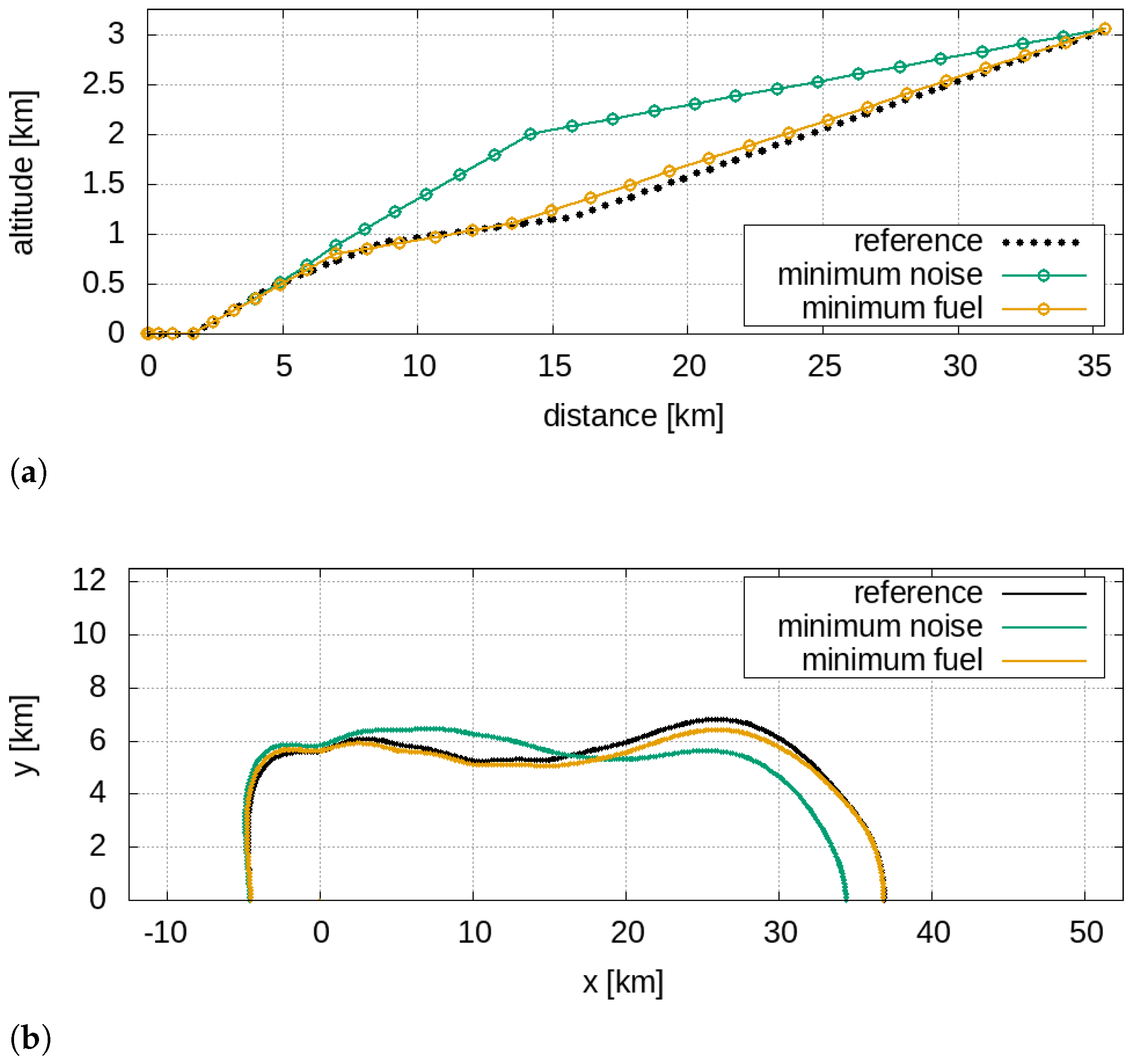
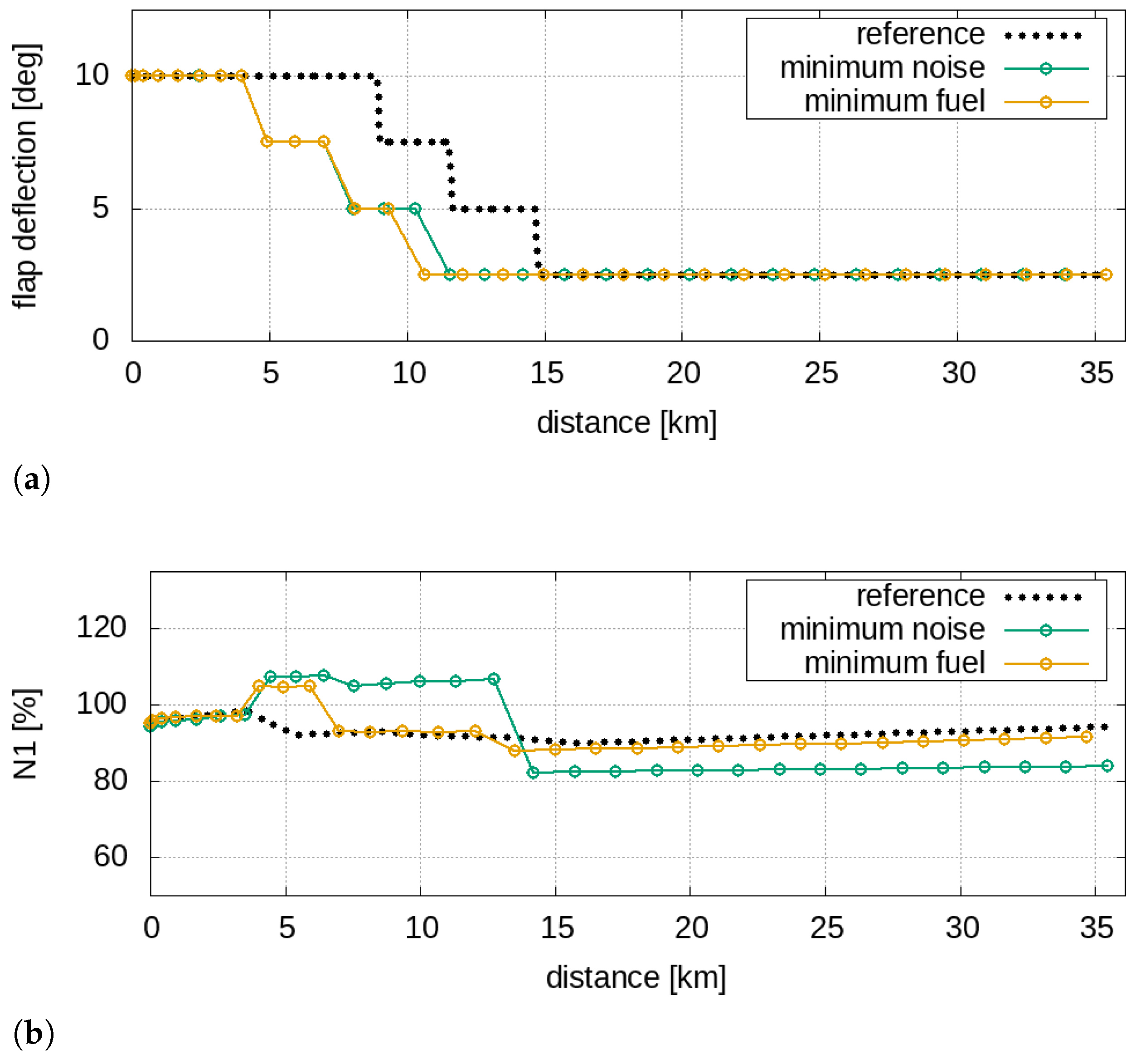
Figure 5a and
Figure 11a (single- and twin-aisle takeoff operations) show the solutions related to the different minimum noise and minimum fuel produce trajectories in terms of geometric, kinematic and procedural variables; even in the codomain, the two solutions turn out to be distant from each other as the contours of the 60 dBA areas have different shapes (see
Figure 5b and
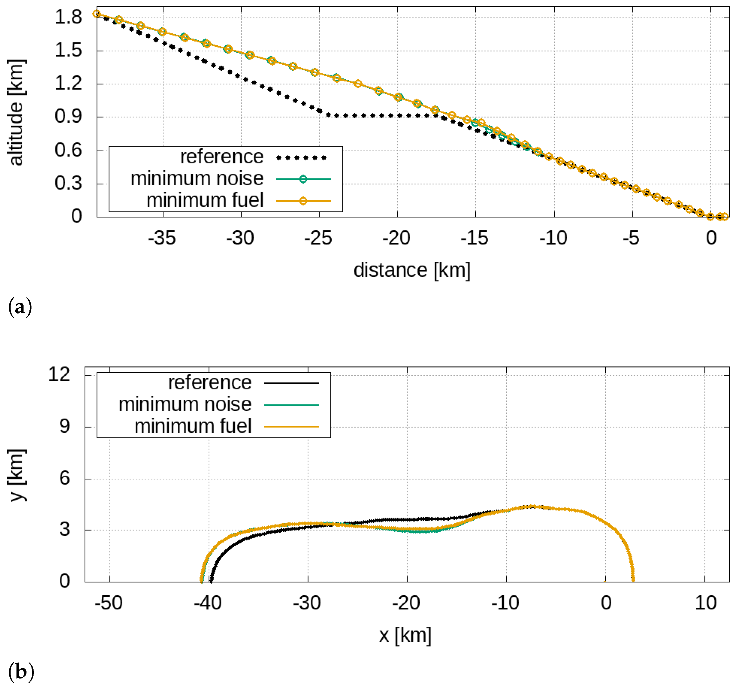
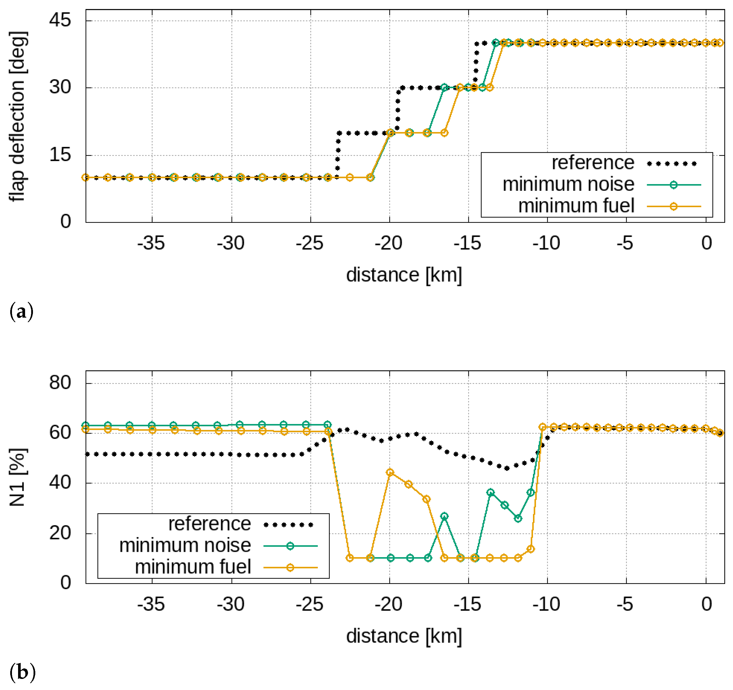
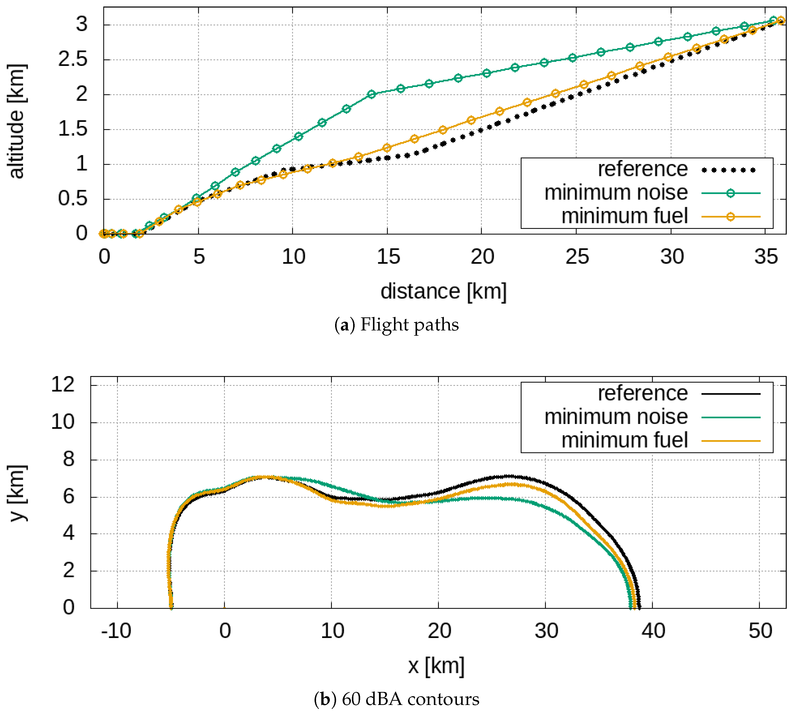
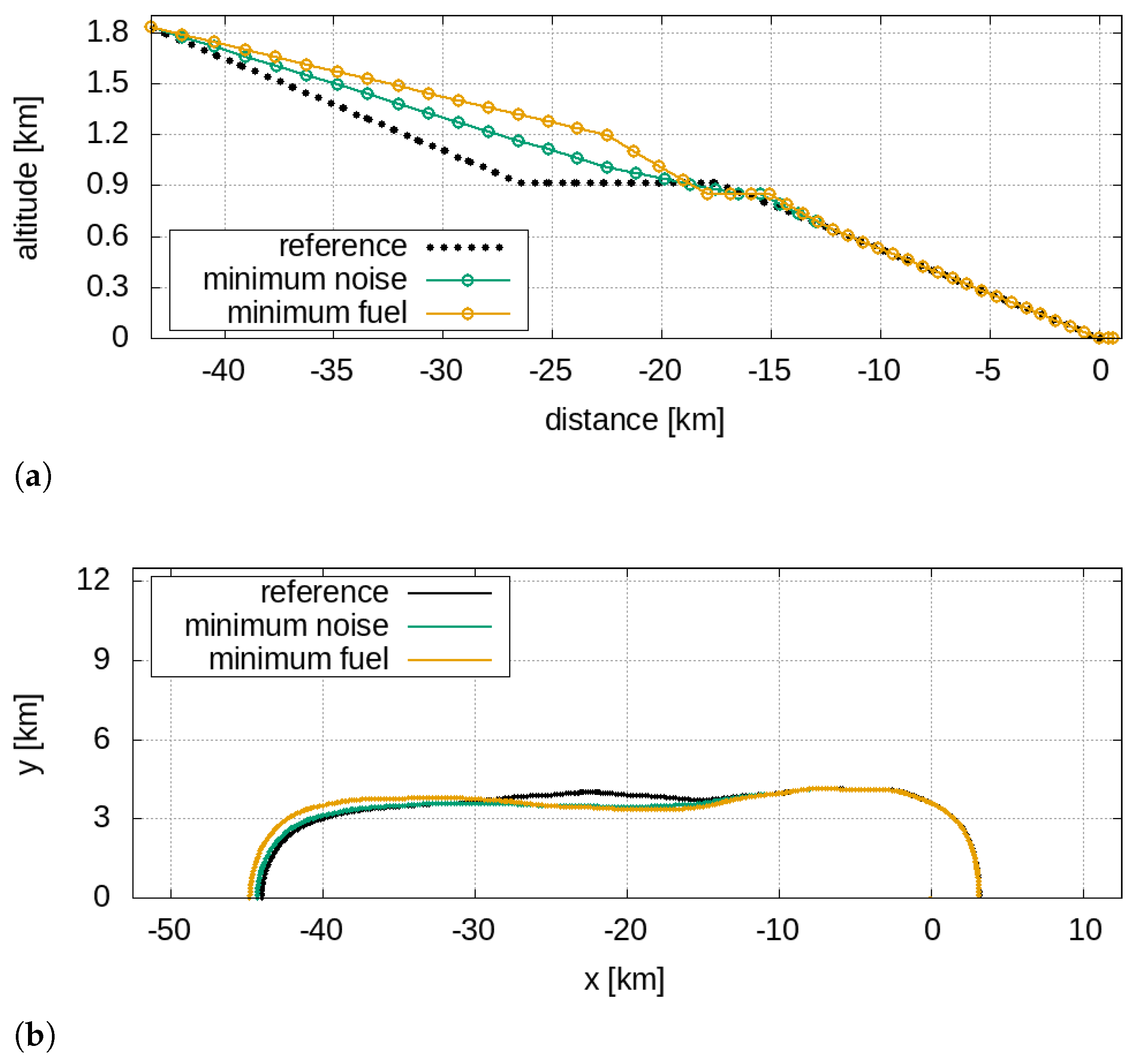
Figure 11b). The minimum noise and the minimum fuel approach operations of the twin-aisle aircraft depicted in
Figure 14a are quite different paths, but
Figure 14b shows that there are no relevant discrepancies between the 60 dBA contours (both different form the reference flight path). As said, this also applies to the 60 dBA contours related to the single-aisle aircraft solutions (in
Figure 8b); in this case, the similarity between the noise footprints is justified by two practically identical trajectories, depicted in
Figure 8a.
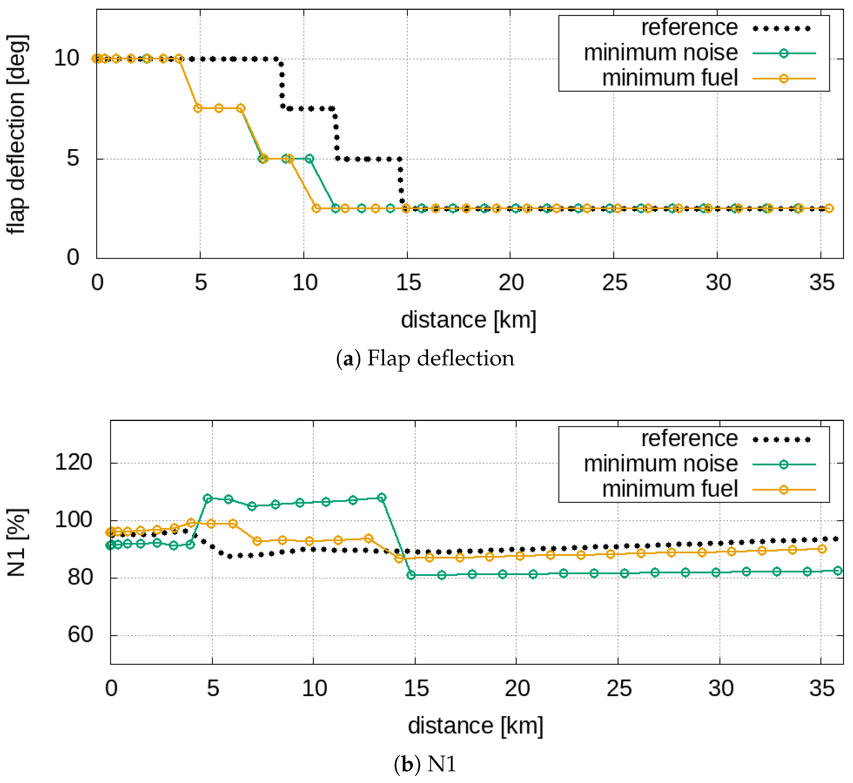
It must be noted that the behaviour of the solutions for the approach manoeuvres (in
Figure 8 and
Figure 14) is not surprising since the entire last part of the flight path is constrained by strict regulations that impose a −3
ramp angle. For the sound quality assessment, let us consider a virtual microphone placed under the flight path at x = −7.5 km (see
Figure 8 and
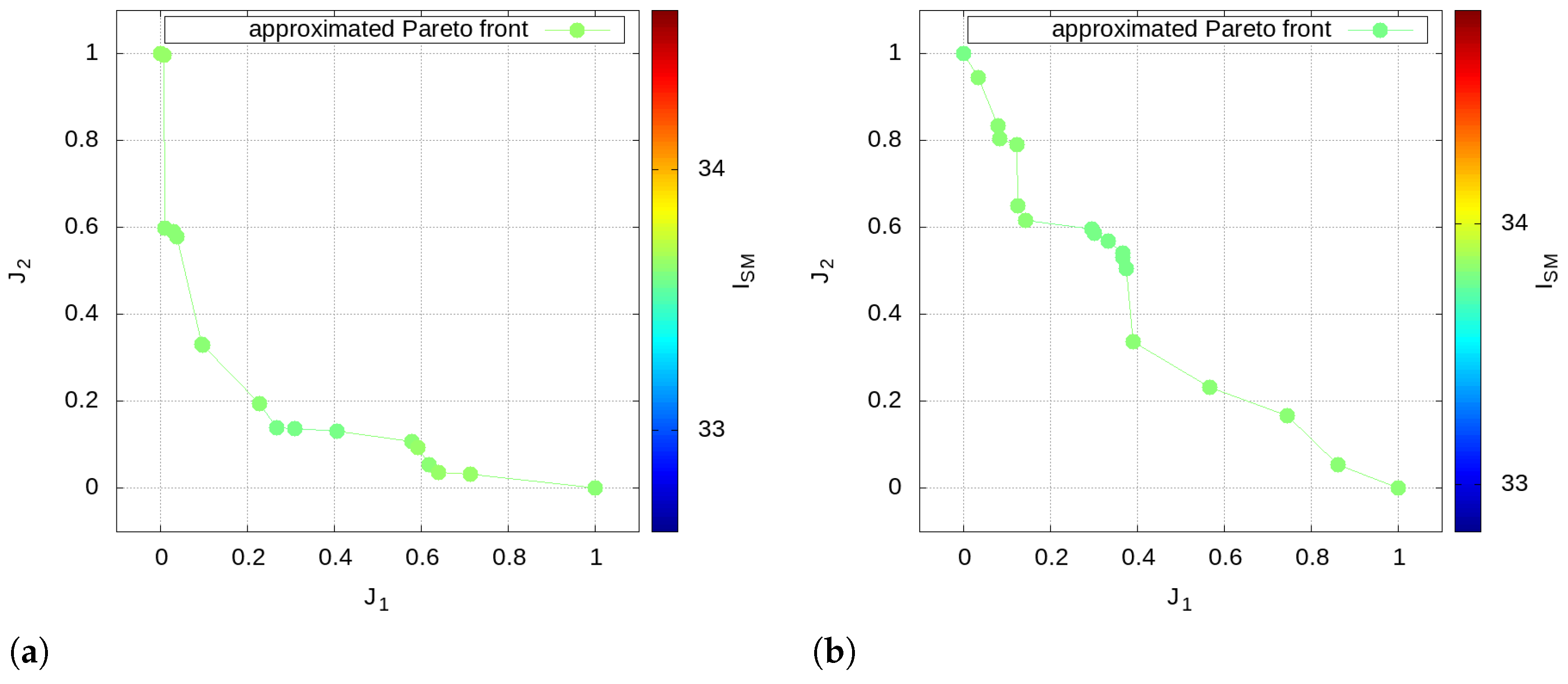
Figure 14) that represents an urbanised location close to the airport boundary; it should be expected that there are no large variations in the time-frequency contributions of noise in landing operations, and this is confirmed by
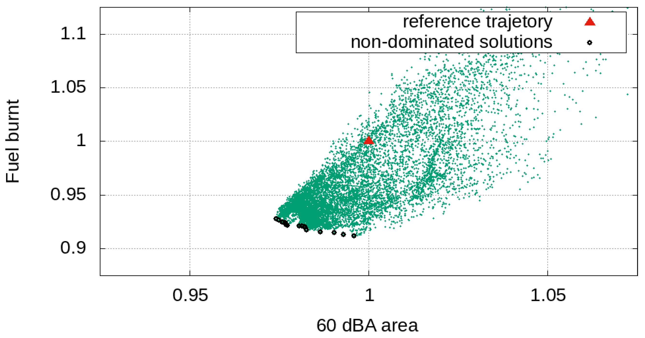
Figure 17, which depicts the mapped approximated Pareto optimal solutions with the sound-matching index
as a parameter for the approach operations.
The designer should therefore choose the trajectory related to the lowest fuel consumption, as each Pareto solution, despite being better than the reference one, is very similar to the others in terms of noise footprint and spectral components
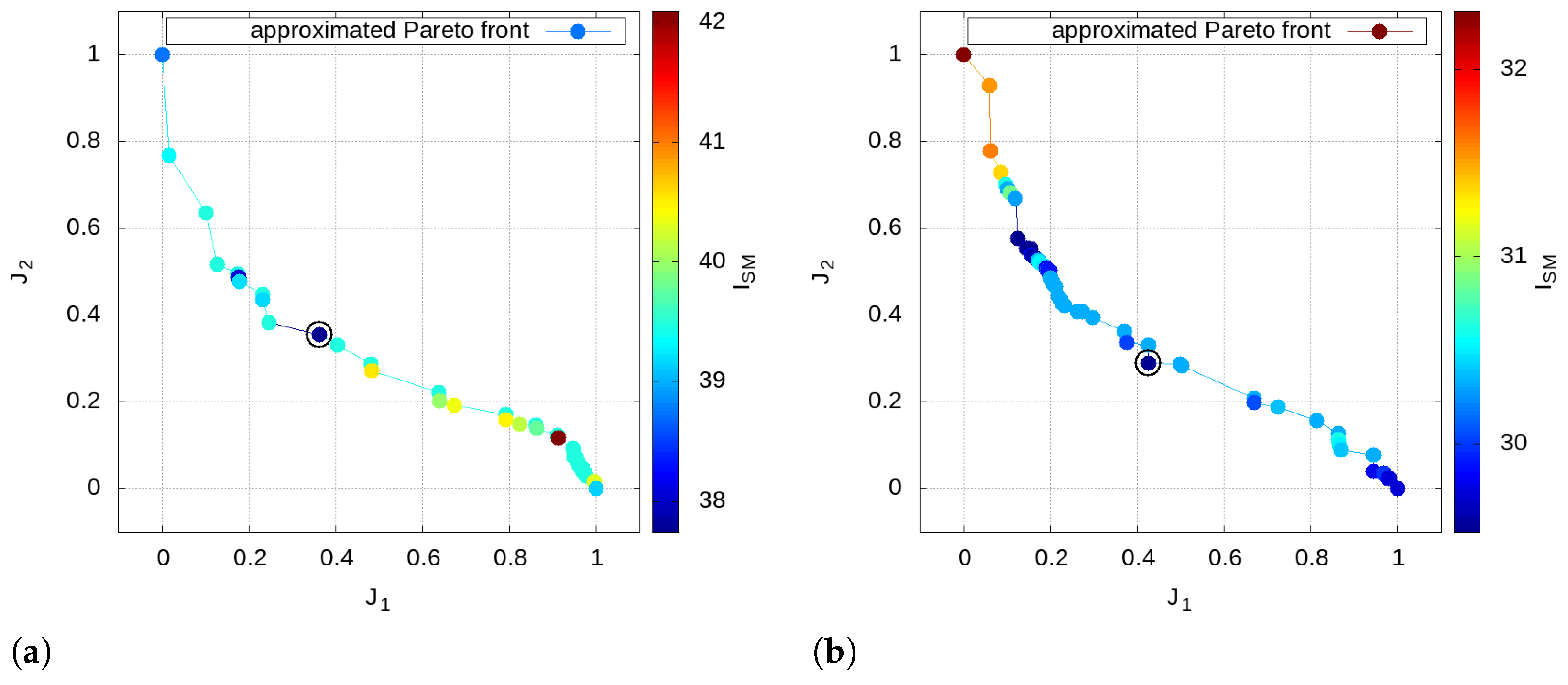
Regarding the takeoff operations, the choice of the optimal solution among the Pareto front is addressed by means of the sound-matching index
using
p = 2 (see Equation (
12)). Let us consider a virtual microphone close to the airport boundary x = 4.5 km;
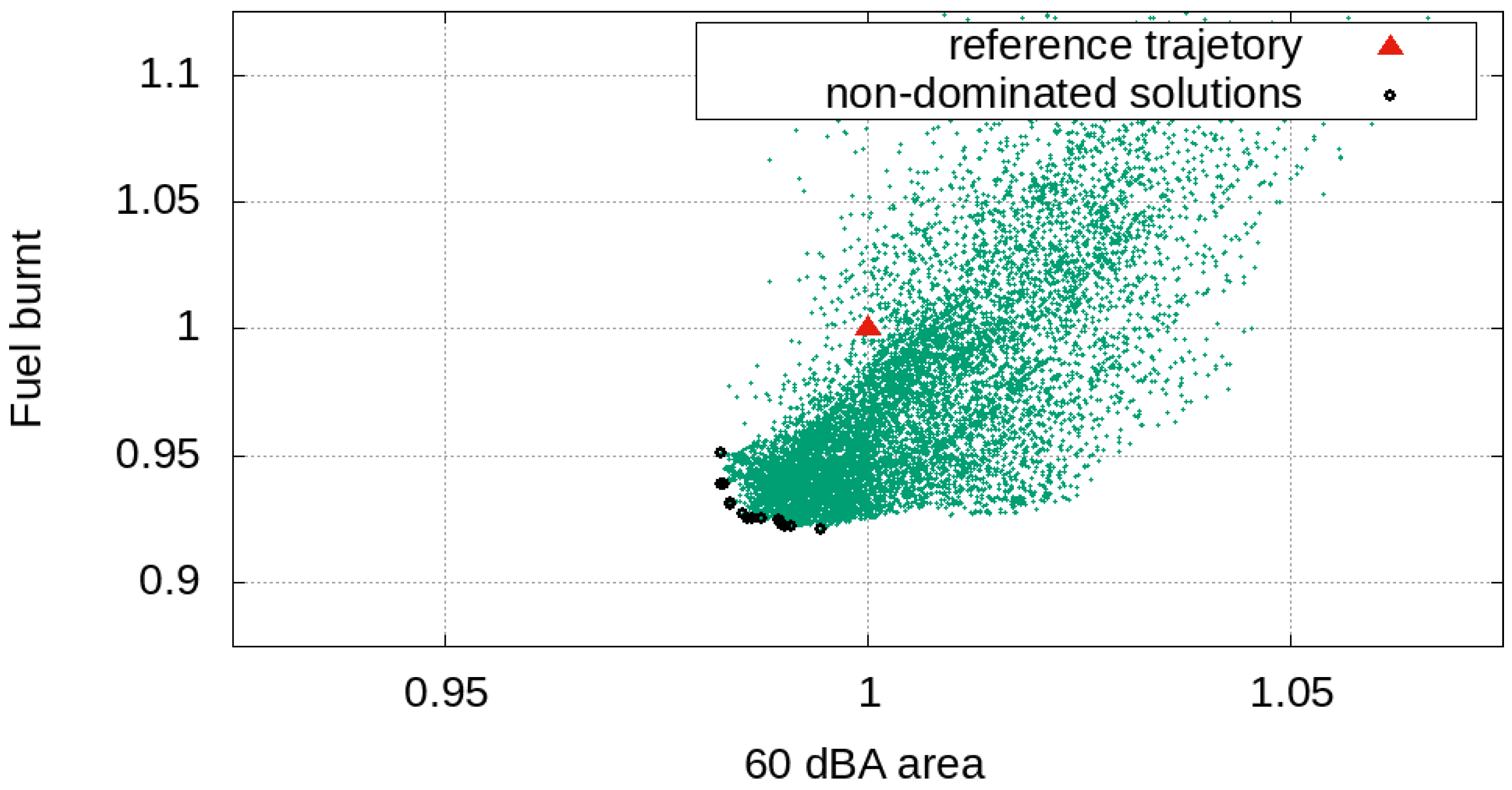
Figure 18 shows the mapped approximated Pareto optimal solutions with the sound-matching index
as parameter related to the takeoff operation for both the single- and the twin-aisle aircraft.
The analysis of
Figure 18 highlights that there is not a specific functional dependency between the 60 dBA contour, the fuel consumption and the spectral content of the noise: indeed, the distribution of
turns out to be in apparently random locations along the Pareto front. It is worth noting that the great variability of the
demonstrates how this approach guarantees the designer an additional degree of freedom in the takeoff optimisation; this could be explained by considering the great sensitivity of the noise tonal components with respect to the variations in the engine operating point during the takeoff operations.


