Article

Design of a Low-Cost Air Bearing Testbed for Nano CMG Maneuvers

by
Charalampos Papakonstantinou
1,*,
Georgios Moraitis
1,
Vaios Lappas
2 and
Vassilis Kostopoulos
3
1
Department of Mechanical Engineering and Aeronautics, University of Patras, 26504 Patras, Greece
2
Department of Aerospace Science and Technology, National Kapodistrian University of Athens, 10679 Athens, Greece
3
Applied Mechanics and Vibrations Laboratory, Department of Mechanical Engineering and Aeronautics, University of Patras, 26504 Patras, Greece
*
Author to whom correspondence should be addressed.
Aerospace 2022, 9(2), 95; https://doi.org/10.3390/aerospace9020095
Submission received: 12 January 2022 / Revised: 9 February 2022 / Accepted: 10 February 2022 / Published: 12 February 2022
(This article belongs to the Special Issue Recent Advances in Spacecraft Dynamics and Control)

Abstract

:
In this paper, a low-cost, miniature spacecraft attitude control simulator is presented for testing miniature actuators such as Nano Control Moment Gyroscopes (CMGs) for simple maneuvers. The experimental setup is composed by an attitude control system (ACS) that mainly consists of a four-CMG cluster in a pyramid configuration and a custom-made air bearing. The one-degree-of-freedom (DoF) air bearing is fabricated to reproduce the frictionless conditions of a nano-satellite in orbit. The ACS is made exclusively using low-cost commercial-off-the-shelf (COTS) components, whilst the air bearing is made using 3D-printed parts. Both hardware and software implementations are described in detail and the performance of the developed simulator is evaluated by two maneuver experiments. Despite the manufacturing imperfections, the ACS is capable of providing higher angular velocities than previously presented in the literature while following the theoretical or simulation data. The results indicate that it is possible to manufacture a low-cost, miniature actuator such as a CMG, using COTS components to demonstrate the operation of an agile nano-satellite. Any deviations from the theoretical values are addressed and several improvements are discussed to further enhance the performance of the air bearing testing platform.

1. Introduction

With over 350 nano-satellites set in orbit between 2020 and 2021 [1], it is evident that nano-satellites are in the front-line of the space industry. Their light weight and the low manufacturing cost allow for technological and scientific principles to be demonstrated in a rapid and effective way. Before achieving challenging tasks such as lunar and Mars landings [2,3], using sophisticated control schemes, it is vital to perform tests in ground-based conditions to ensure the success of a space mission which takes place either in micro-gravity or zero-gravity conditions. Simulating the space environment in a laboratory is a complex task. Ground simulations of the attitude control system (ACS), one of the most challenging subsystems of the satellite, are commonly achieved using air bearings because they establish a thin film of air capable of supporting the experimental equipment in a near-frictionless way. Air bearings are usually divided in three main types. Planar air bearings allow only translational movements, while rotational air bearings allow the rotation around at least one of the roll, pitch or yaw axis. On the other hand, the combinational air bearings offer enhanced capabilities by moving the ACS in six or fewer degrees of freedom (DoF). A wide range of air-bearing-based spacecraft simulators has been developed. The most recent of them are manufactured for nano and micro-satellite testing and are presented below.
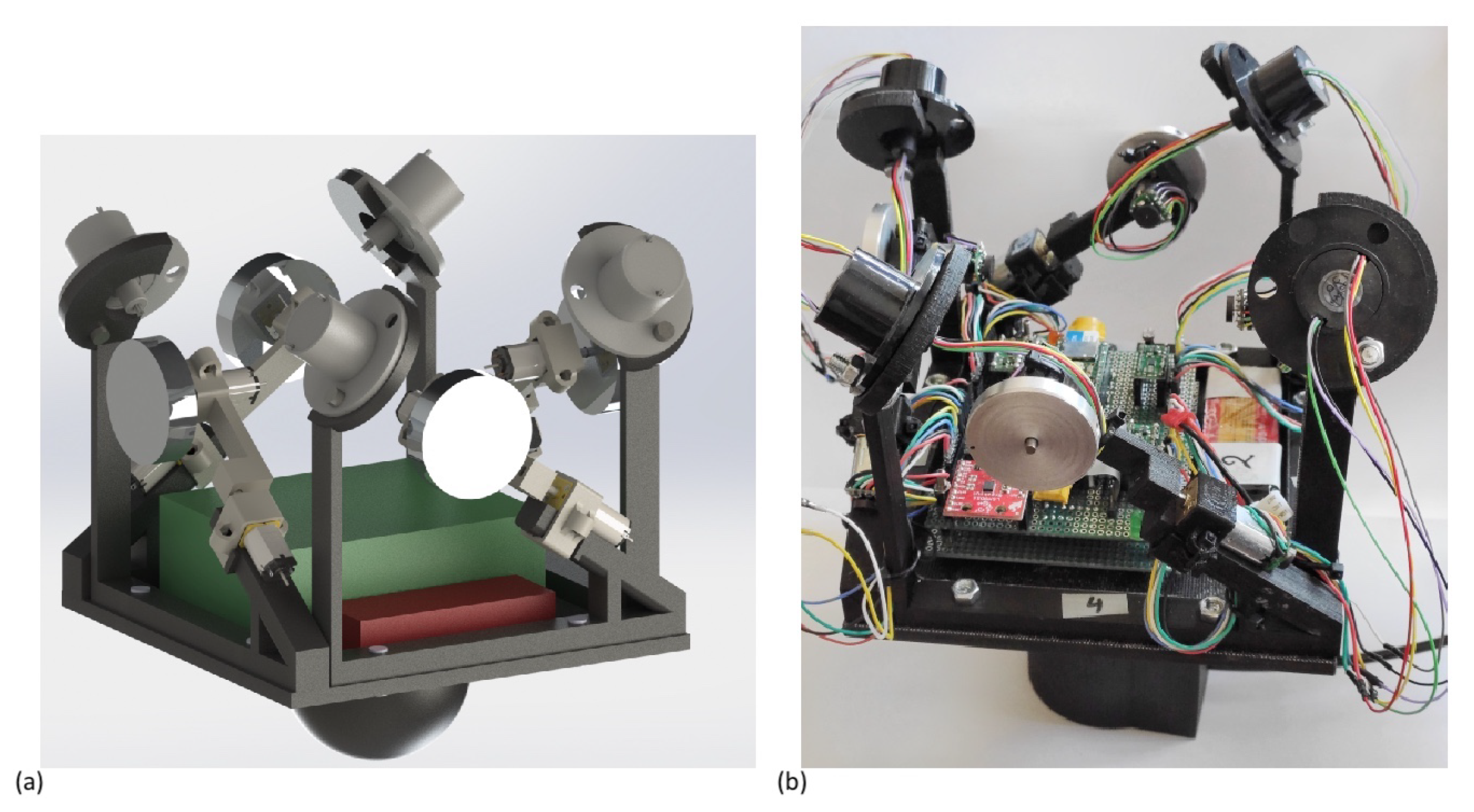
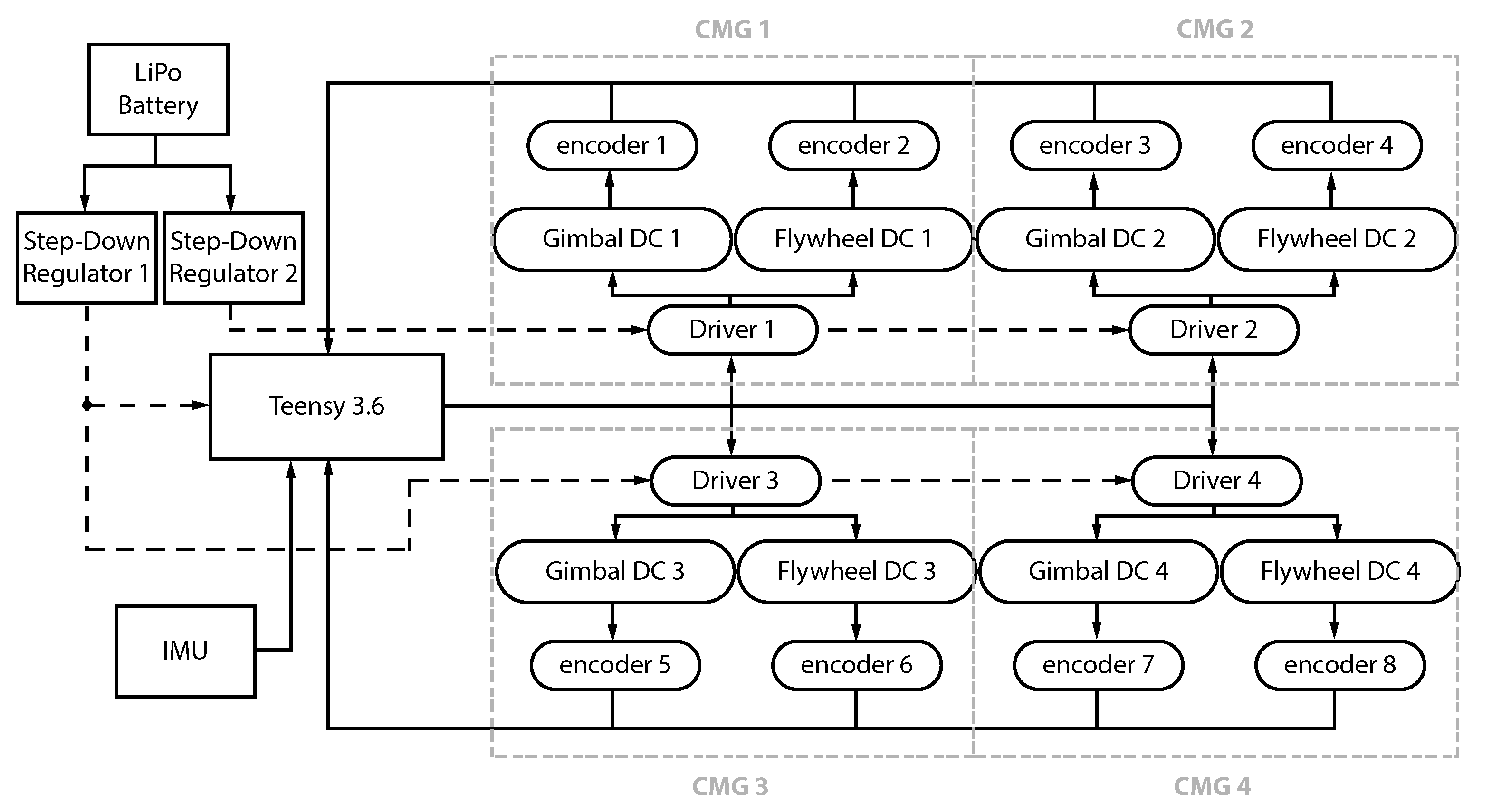
The Space Vehicle Control Group at the University of Surrey has also used a one-DoF air bearing table to demonstrate the benefits of the miniaturization of control moment gyroscopes (CMGs). Four CMGs are used in pyramid configuration controlled by a Siemens 8 bit C515 microcontroller, while an inertial measurement unit (IMU) by Crossbow Technology Inc. is used to measure the angular rate of the platform [4]. Utilizing all four CMGs for a manoeuvre about the vertical axis, the cluster is capable of rotating the platform with a maximum angular velocity of 8.41 deg/s. Another tabletop-style, hemispherical air bearing is described in [5]. A circular disk of 30 cm in diameter and thickness of 10 mm is developed for testing the behaviour of nano-satellites, up to 2U CubeSats. The testbed is based on an Arduino Mega 2560 board and it is equipped with a 9-DoF Sparkfun IMU along with three reaction wheels for attitude determination and control. An extremely simple apparatus with cost of less than $20 made exclusively for educational purposes is presented in [6]. It consists of an air bearing made by casting polyester resin and a billiard ball that is used for rotational motion and precession demonstrations. The Naval Postgraduate School has also designed an air bearing platform for testing the ACS of the micro-satellite NPSAT1 [7]. The air bearing allows a maximum tilt angle of 32 deg about the horizontal plane and a 360 deg motion about the vertical axis. The testbed is designed to hold up to 82 kg, requiring approximately 24 psi of air pressure supply. Another attitude simulator, CubeTAS, is developed for nano-satellite testing. It is based on PC-104 form factor and an ARM9 processor [8]. The bottom part of the air bearing is a hemisphere with diameter of 250 mm and the rotational motion is limited to ±50 deg about the horizontal plane. An IMU and three reaction wheels are used for attitude determination and control, while a Helmholtz cage is installed around the platform to simulate the Earth’s magnetic field. York University has presented another nano-satellite attitude simulator which makes use of a commercial-off-the-shelf (COTS) air bearing designed by Nelson Air [9]. The testbed is based on a Linuxstamp II, and it is equipped with an ADIS16364 six-DoF IMU and three orthogonally mounted reaction wheels. A cubesat attitude control simulator was developed by the Massachusetts Institute of Technology, based on a tabletop air bearing with diameter of 12.4 cm [10]. Four flywheels operating either in reaction or momentum wheel mode are used while the ADIS 16365 IMU made by Analog Devices and the three-axial MicroMag3 made by PNI Corporation are the sensors of the system. The platform is controlled by two Arduino Mega boards. Another tabletop-style aerostatic bearing was developed by the Instituto Tecnológico de Aeronáutica of Brazil [11]. It consists of three-axial gyroscopes and a set of three orthogonally installed reaction wheels that can provide a maximum manoeuvring speed of 0.33 deg/s. An air bearing with a porous carbon surface has been used by the Aerospace Engineering Department of the United States Naval Academy [12] for micro-satellite testing. The tests include a 11.3 kg platform, based on an Arduino processor, an Adafruit 9-DoF IMU for attitude determination and a set of four reaction wheels for controlling orientation of the platform. The simulator and the actuators are designed to follow the requirement of a desired agility of 4 deg/s. Another air bearing in tabletop configuration that makes use of four reaction wheels and an AHRS sensor has been developed by the Department of Mechanical Engineering of University of Isfahan for testing of a 40 kg platform [13]. An attitude control testbed for cubesats was built by the Virginia Polytechnic Institute and State University using COTS components [14]. A tabletop-style air bearing manufactured by Space Electronics Inc. is used and the platform is controlled by a Beaglebone Black—Rev C board. The VN-100 IMU/AHRS by VectorNav, which embeds a three-axial magnetometer, accelerometer and gyroscope along with a barometric pressure sensor, determines the attitude of the testbed. No actuators for attitude control are present on the simulator. A cubesat and nano-satellite simulator is presented in [15]. A PLA 3D-printed sphere encloses three reaction wheels, two perpendicular magnetorquers, an EZ-COMPASS-4 and a Sparkfun MPU-9150 for attitude control and determination. Both sensors and actuators are controlled by a Raspberry PI 2 Model B board. Three distinct experiments were performed, each one for every axis demonstrating a maximum angular velocity of less than 2 deg/s. The Laboratory of Application and Innovation in Aerospace Science of the University of Brasília has manufactured a nano-satellite attitude simulator that consists of a custom made tabletop air bearing that limits the motion to ±45 deg about the horizontal plane [16]. An ATMEGA8 is the main computer of the testbed, an ADIS16400 IMU controls determines its orientation and there are no actuators on the platform for attitude control. Another attitude simulator for testing nano-satellite missions in low Earth orbit is presented in [17]. The facility is capable of simulating both the light coming from the Sun and the Earth’s magnetic field through COTS LED Studio and Helmholtz cage. The tabletop-style air bearing used was made by Serviciencia and the platform is based on an Arduino Due board. The platform is equipped with magnetometer and a monochromatic CMOS camera that is used as a sun sensor while a custom monocular metrology vision system is also implemented for ground-truth attitude determination. With a total cost of less than 20,000 euros, the attitude simulator does not embed any actuators for attitude control. A 3D-printed air bearing has been manufactured by Aalto University [18]. The air bearing is made of PLA and two hollow hemispheres that connect through latching pieces form a full sphere that consists the rotor of the system. Directional air nozzles compensate for the disturbances produced by fabrication imperfections. A visual tracking system based on OpenCV library is used to perform torque measurements by calculating the angular velocity of the rotor through fixed markings on it.
It is evident that CMGs have not been commonly used in spacecraft attitude control simulators, even though it is proven that they offer enhanced torque capabilities that meet the maneuvering requirements of agile satellites [4,19]. Reaction and momentum wheels are widely found because they are affordable and easier to make since they use fewer moving parts compared to CMGs. In this paper, a simple and affordable approach is presented to fabricate a four-CMG cluster in pyramid configuration using COTS components. A custom-made 3D-printed air bearing that provides one rotational DoF about the vertical axis is also designed for testing. The experimental results follow the theoretical values and they confirm that it is feasible to demonstrate high manoeuvring capabilities using COTS components.

2. System Overview

The objective in the work presented is the development and evaluation of a 4-CMG pyramid cluster to be used for attitude control through practical testing on a low-cost air bearing simulator. The system should be designed to fit into a nano-satellite with a maximum mass value of under 2 kg while remaining at a reasonable cost. Moreover, specific maneuverability criteria have to be followed, as described in the Sizing section.
The developed Attitude Control System (ACS) is composed of actuators and electronic components that are mounted in a hemispherical structure in tabletop configuration. The main parts of the ACS are divided in hardware and software, as presented below.

2.1. Hardware

All electronics are mounted on top of a 3D-printed ABS rectangle plate with a hemispherical base while the total size of the platform with the CMGs employed is 17.8 cm × 17.8 cm × 18.3 cm. The 3D CAD model is shown along with the experimental setup in Figure 1a,b, respectively.
The parts that comprise the ACS hardware are the main perfboard along with the microcontroller and the Inertial Measurement Unit (IMU), the battery and the four CMGs. The location of the equipment on the platform has been as symmetric as possible. The mass of each component and the total mass are described in Table 1.

2.1.1. CMGs

A 4-CMG cluster in pyramid configuration is used for the attitude control of the platform. The main parts of the cluster are the eight micro DC motors. Four Pololu 3058 motors are used to implement the gimbals while four Pololu 3082 motors are used as flywheels. The gear ratio of the gimbal and flywheel motors, g r , equals to 1006:1 and 5:1, respectively. A magnetic encoder is placed on the shaft of every motor. Each encoder is a dual-channel Hall Effect sensor board in combination with a 6-pole magnetic disc. The resolution they provide is 12 counts per revolution of the motor shaft and it can be converted in counts per revolution of the gearbox output shaft, c p r g , through the following equation:
c p r g = 12 · g r
The angle accuracy in degrees, a c c , can be measured for each type of motor by:
a c c = 360 c p r g
Table 2 presents the details of the motors used.

2.1.2. Perfboard

To enable a full 360 deg rotation about the gimbal axis for each CMG, the 6-Wire SRC022 slip ring by Adafruit is used. The motors’ nominal voltage is 6 V. The flywheel of each CMG is made of aluminum and has a radius of 17 mm and a mass of 14.1 g. The flywheel is locked on the motor axis using two headless hexagon M1.6 socket screws placed in an anti-diametrical configuration. The motor drivers, the voltage regulators along with the IMU and the microcontroller are all mounted on a perfboard equipped also with LED units and a photo-resistor for start-stop control. The dimensions of the perfboard are 95 mm (length) × 77.5 mm (width) × 26 mm (height). In order to keep the weight of the structure as low as possible, only two Pololu 5 V, 1 A, S7V7F5 step down regulators are used to power the motors’ drivers and the microcontroller. Four Texas Instruments DRV8835 motor drivers are used to control the eight DC motors. The microcontroller used is the Teensy 3.6 board which embeds an ARM Cortex-M4 processor at 180 MHz, 1 M Flash and 256 K RAM. It is selected because it provides enough interrupt pins to read both channels of each encoder and there is a prior knowledge of using this board. The experimental data are saved in an SD card placed in the microcontroller’s built-in slot. SparkFun LSM9DS1 is selected as the IMU of the system. It is a 9-degrees-of-freedom (DoF) sensor and it is utilized in I 2 C mode with gyro resolution of 0.00875 deg/s. A LiPo 2S 7.4 V 800 mAh battery that powers the system is placed next to the perfboard. Figure 2 illustrates the electrical connection of the components.

2.1.3. Air Bearing

The main challenge of the ground-based tests is that they take place in an Earth’s gravity environment, whilst the major operation of such systems is in a gravity-free environment while in orbit. The ACS is placed on a tabletop-style 3D-printed structure because initial tests included the motion of the platform about all three axes, roll, pitch and yaw. Due to the simplicity, the small size and weight of the simulator, no automatic balancing system was implemented for torque disturbance compensation and the CoM was meant to be positioned manually using counterweights. Such an approach was not feasible because of two main reasons. The first is that the CoM in the horizontal direction becomes significantly difficult to be adjusted when correcting the CoM in the vertical axis. The second is that the CoM of each CMG changes as the gimbal rotates even though each one was designed to be as symmetric as possible. This is mainly due to the cables coming out of the flywheel connected to the slip ring and small manufacturing and assembling imperfections. Thus, an 1 DoF experimental setup is selected to validate the ACS that allows the rotation only about the yaw axis. The height of the air bearing bottom part is 58.9 mm with a external diameter of just 60 mm. However, due to the 3D printing process a flat side is required to lie the air bearing, increasing the size in one of the axes by 6.2 mm, as depicted in Figure 3.
A configuration of three rows of holes was found to work efficiently for the developed air bearing even though no further analysis and optimization were conducted. The first row only contains the center hole whilst the second and the third rows contain 9 and 19 holes, respectively. Each hole has a diameter of 1 mm. The angle of the holes with respect to the horizontal plane are 90 deg, 105 (or 15) deg and 120 (or 30) deg for the first, the second and the third row. The number of holes for each row is selected so that the air bearing is operational while not presenting imbalances. However, the configuration of the air bearing will be further studied and optimized in future designs. Table 3 summarizes the main characteristics of the bottom part of the air bearing platform.
The top part of the air bearing is shown in Figure 4. The ABS rectangle plate was also 3D-printed with dimensions 14.4 cm × 14.4 cm × 5.1 cm. The strength combined with the lower density of ABS compared to this of aluminum allows for less mass and, as a result, lower moment of inertia, while improving the maneuverability of the system. Low printing velocity, heated bed and raft are used to ensure the minimum thermal strain and avoid warping. The diameter of the 3D-printed air bearing at its highest point is 60 mm. The printing accuracy is 0.15 mm, so the surface is slightly finished using only P2000 sandpaper. Alternatively, an acetone steam bath can also be used for smoothing. Each CMG is fixed on the plate using two M5 bolts.
The hemispherical top part of the 3D-printed structure was locked in horizontal position preventing the system from rotating about the roll and the pitch axes using a thin bolt (Figure 5) which enters the center hole of the air bearing.
A thin film of air physically separates the upper spherical part from the base, which is also made of 3D-printed ABS. The air pressure is provided through a control switch by a Bormann MY2400, 1 hp, 24 lt, and a typical operation requires approximately 25 psi. The air supply is connected to the air bearing using a 4 mm plastic push-in swivel elbow fitting. At this pressure, the air compressor allows approximately 2 min of experimental time before the pressure drops below that value.

2.2. Software

The microcontroller is programmed in C. Both channels of each encoder are exploited to calculate the gimbal angles through interrupt pins. The IMU is utilized in I 2 C mode, while a low-pass filter is used to eliminate the measurements noise. A set of one hundred samples is used for bias correction, while no temperature compensation is needed. The IMU sensor operates for about 30 s and negligible temperature change is observed in this time period. However, the built-in functions found in the LSM9DS1 library allow for the magnetic data compensation by temperature, setting the first bit of the CTRL_REG1_M register to 1, in case there is a considerable temperature change. Different measurements were obtained by the IMU sensor to define the attitude of the platform while it is stationary. Six different cases were examined, depending on whether both the gyroscope and the magnetometer of the IMU are exploited to define the yaw angle. Table 4 explains each case.
The results of each case are shown in Figure 6 and the value of the standard deviation is presented in the bottom left corner of each subplot.
The minimum standard deviation is 0.0973 deg and it is presented for case 3, where only the gyroscope is used, after bias correction and low-pass filtering. An angle drift of 0.0124 deg/s is achieved in this case and it is the minimum of all cases. Thus, the attitude determination is provided only by the gyroscope data and the low pass filter is given by
G n = ( 1 f g ) G n 1 + f g G n i m u
where G n is the filtered gyroscope value at nth iteration, G n i m u is the gyroscope measurement provided by the IMU after the bias correction at nth iteration. f g denotes the smoothing factor and it is equal to 0.25 for this experimental setup. The loop cycle is selected to be 0.05 s as this is the maximum time period needed to collect the input data from the IMU, execute all the required calculations and write the output data to an SD memory card connected to the native SD Card port of the microcontroller. A flow diagram of the air bearing operation processes that take place is presented in Figure 7.
At first, the SD card is prepared, and a warning message is shown if the initialization has failed. The definition of input, output and interrupt pins follows in order to control the gimbals as presented in the next step. Due to the nature of the encoders, it is possible to achieve only a relative gimbal angle value. This limitation requires the initialization of the gimbals angles to the preferred values in the beginning. Afterwards, the establishment of I 2 C communication takes place that allows to read the data from the IMU and the sensor is calibrated. Eventually, before the beginning of the main operation, the flywheels are spun up to their operational angular velocity and they are stabilized through a PID controller which remains active through the whole operational time.
In order to avoid any undesired behaviour, the gimbal rates are saturated according to the following formula:
δ ˙ s a t = δ ˙ δ ˙ t h max ( | δ ˙ 1 | , | δ ˙ 2 | , | δ ˙ 3 | , | δ ˙ 4 | )
where δ ˙ t h is a preset threshold. It is preferred to saturate the gimbal angle rates using Equation (4) over applying a boundary value to every gimbal angle rate that exceeds the required threshold because the characteristics of the motion are conserved. The saturation threshold is selected to be the minimum value of the maximum gimbal velocity of the four gimbals. The motor driver takes as input a pulse width modulation (PWM) signal for speed control. Thus, it is required to map each angular velocity of the gimbal to a PWM value, in order to control the CMG cluster. As expected, only an approximation of this is feasible in practice. After achieving the steady-state velocity for the four flywheels, each gimbal is spun up gradually by increasing the PWM value, while measuring its angular velocity. Figure 8a–d shows the relation between the PWM values and the gimbal rates for each CMG. The equations of the linear approximations that are used to map the commanded gimbal rates to PWM values are also shown in the figure. It is observed that the maximum gimbal velocities are lower than the no-load velocities referred to in the datasheet because of the load they support and the fact that they operate at 5 V instead of their nominal value of 6 V. A cascade control design is implemented and an inner PD controller is used to guarantee that given the commanded gimbal rates, the gimbals follow the desired angle profiles.

3. Flywheel Sizing

The system is to be tested using an 1 DoF simulator that allows the rotation of the ACS about the yaw axis. A maneuver of 30 deg should be completed in 2 s and this requirement is used for sizing the CMG cluster. Allowing an design error margin, a 2 kg cuboid satellite is selected as reference for sizing. The moment of inertia, J, is the same for every axis and it is used to find the required torque, N r e q . This is calculated by:
N r e q = J a ( t a / 2 ) 2
where a is the rotation angle completed in t a seconds. Figure 9 illustrates the acceleration and deceleration phases of the system.
The angular momentum h 0 can be calculated through Equation (12) and the following equation:
N c m g = h × δ ˙
where N c m g ϵ 3 x 1 is the total torque generated by the cluster. Due to the symmetric rotation of the gimbals, i.e., δ 1 , δ 2 , δ 3 , δ 4 = δ , and assuming that the maximum gimbal velocity, δ m a x , is the same for all CMGs, the torque for a manoeuvre about the yaw axis is given by
N r e q = 4 δ ˙ m a x h 0 cos δ sin β
For δ = 0 , the required momentum h 0 can be found. This value is used to compute the moment of inertia, I f through Equation (13).
The mass of each flywheel disk, m f , can be easily calculated considering the moment of inertia of a cylindrical tube:
m f = 2 I f ( z 1 2 + z 2 2 )
for given inner and outer radius z 1 , z 2 . The disks are made of aluminum, with a known density of ρ a l . The mass calculated in the previous step is used to specify the height of the flywheel disks L f , considering the volume of the cylindrical tube as:
L f = m f ρ a l π ( z 2 2 z 1 2 )
The numerical results of the sizing analysis are presented in Table 5.

4. Dynamic Model

The equation of motion of a rigid spacecraft is described by:
ω ˙ = J 1 ( ω × ( J ω ) h ˙ ω × h + T e x )
where T e x ϵ 3 x 1 is the vector that contains the external torques applied to the spacecraft and ω ϵ 3 x 1 represents the angular velocity of the spacecraft with respect to the body frame. A control torque, T c ϵ 3 x 1 , can be selected as [4]:
h ˙ + ω × h = T c
where h ϵ 3 x 1 is the angular momentum of the CMG cluster:
h = h 0 c β s δ 1 c δ 2 + c β s δ 3 + c δ 4 c δ 1 c β s δ 2 c δ 3 + c β s δ 4 s β s δ 1 + s β s δ 2 + s β s δ 3 + s β s δ 4
s, c are the abbreviations for sin and cos, respectively. The parameter β denotes the skew angle of the 4-CMG cluster in pyramid configuration and it is chosen in such a way that the momentum envelope is nearly 3-axis-symmetric and spherical. h 0 is the magnitude of the momentum of each flywheel and it is given by:
h 0 = I f ω f
where I f and ω f are the moment of inertia and the angular velocity of the flywheel. Let every flywheel operate at the same angular velocity and have the same moment of inertia. Then, h 0 is a scalar quantity.
In general, the momentum derived from the CMG cluster is a function of the gimbal angles δ = [ δ 1 , δ 2 , δ 3 , δ 4 ] T ϵ 4 x 1 for a spacecraft employed with 4 CMGs. Assuming that the control torque is known, the relation between the total CMG momentum rate and the gimbal angles rates can be derived by the equation:
h ˙ = A ( δ ) δ ˙
The matrix A ( δ ) ϵ 3 x 4 is the Jacobian matrix of the system and except for the gimbal angles, the Jacobian matrix depends on geometric characteristics of the CMGs such as the skew angle. For the 4-CMG cluster, the Jacobian matrix is given by:
A ( δ ) = c β c δ 1 s δ 2 c β c δ 3 s δ 4 s δ 1 c β c δ 2 s δ 3 c β c δ 4 s β c δ 1 s β c δ 2 s β c δ 3 s β c δ 4
The gimbal angle rate vector δ ˙ ϵ 4 x 1 can be calculated by:
δ ˙ = A # ( δ ) h ˙
Since the Jacobian matrix is not rectangular, several definitions have been discussed for the inverse of the Jacobian matrix A # ( δ ) [20].
The satellite’s kinematics equation of motion expressed in quaternion form is the following:
q ˙ = 1 2 q ω q
where ⊙ denotes the quaternion multiplication and q = [ q 0 , q 1 , q 2 , q 3 ] T ϵ 4 x 1 represents the attitude quaternion. ω q = [ 0 , ω T ] T ϵ 4 x 1 is the angular velocity ω of the satellite expressed in quaternion form. For two quaternions r = [ r 0 , r 1 , r 2 , r 3 ] T ϵ 4 x 1 and p = [ p 0 , p 1 , p 2 , p 3 ] T ϵ 4 x 1 , the quaternion multiplication is calculated by:
r p = p 0 r 0 p 1 r 1 p 2 r 2 p 3 r 3 p 0 r 1 + p 1 r 0 p 2 r 3 + p 3 r 2 p 0 r 2 + p 2 r 0 + p 1 r 3 p 3 r 1 p 0 r 3 p 1 r 2 + p 2 r 1 + p 3 r 0
For the implementation of the attitude control, the control torque T c applied on the satellite’s body is a function of the vector part of the error quaternion q e r r and ω , as described by the following equation:
T c = ( K p q e r r v + K i q e r r v d t + K ω ω )
The error quaternion between the current attitude quaternion and the commanded quaternion q c is:
q e r r = q e r r s q e r r v = q c * q
where q e r r s and q e r r v = [ q e r r r o l l , q e r r p i t c h , q e r r y a w ] T are the scalar and the vector part, respectively, and q c * expresses the conjugate quaternion of q c = [ q 0 c , q 1 c , q 2 c , q 3 c ] T ϵ 4 x 1 . The normalization of the quaternions is required before evaluating the q e r r . The “3-2-1” sequence is used to convert the quaternion error to the corresponding Euler angles error, as presented in figures in the Simulation Results section.
Since the simulation describes a discrete time system, it is required to integrate the quaternion rate q ˙ at the ith iteration, as provided in Equation (17) using the equation:
q i = q i 1 [ cos ( | | ω | | d t 2 ) , ω | | ω | | sin ( | | ω | | d t 2 ) ] T
where d t is the time step between two consecutive iterations.

5. Experimental Setup—Results

In order to validate the operation of the ACS, two different experiments are conducted. In the first, the platform has to complete an 180 deg manoeuvre about the yaw axis as expressed by the q c = [ 0 , 0 , 0 , 1 ] T . In the second, a 90 deg manoeuvre about the same axis is commanded as given by the quaternion q c = [ 0.7071 , 0 , 0 , 0.7071 ] T . It is assumed that the system has reached the steady state when the attitude error a e r r remains below a preset threshold for a given time t s s . The parameters K p , K i and K ω denote the control gains. Initially, the selection of a high K p gain leads to a highly oscillatory response and K i can be used to correct the steady-state error. K ω is then tuned to reduce the overshoots and converge faster to the desired attitude. The values of the parameters used in the experiments are presented in Table 6.
Figure 10 and Figure 11 present the experimental results for the 180 deg manoeuvre. The theoretical data, also shown in each figure, are obtained using the moment of inertia of the system about the vertical axis as measured by the CAD model of Figure 1a and is equal to J = 0.00283 kgm 2 . Figure 10a illustrates that the system immediately responds to the commanded attitude as it begins to rotate about the positive yaw of the axis. The steady state, as defined previously, is reached at about t = 20 s and the rising time of the system is only 3.7 s. This indicates that the platform has gained a high angular velocity, as shown also in Figure 10b. The maximum angular velocity achieved is 53.47 deg/s at t = 1.9 s and it follows the theoretical angular velocity profile, which presents a maximum value of 51.38 deg/s at t = 1.6 s. The mean angular velocity through the whole manoeuvre is 8.32 deg/s. The experimental results differ slightly from the theoretical and a minor time delay is observed in the response due to the low-pass filter used to eliminate the sensor noise. However, the system is capable of completing the commanded maneuver with an accuracy of 1.5 deg tightly following the theoretical profile. The gimbal angles of the four CMGs in the cluster are presented in Figure 11a, Figure 11b, Figure 11c and Figure 11d, respectively. Both minimum and steady-state values of each gimbal are shown in Table 7. The average MAE for this experiment for gimbal angles δ 1 , δ 2 , δ 3 , δ 4 , attitude error and angular velocity, as derived by 5 sets of measurements are 4.1654 deg, 4.5314 deg, 7.9983 deg, 15.3848 deg, 3.3122 deg and 1.7429 deg.
Figure 12 and Figure 13 present the results for the 90 deg maneuver. It is observed that the system follows the theoretical attitude and attitude velocity profile as in the previous experiment. A maximum angular velocity of 32.8 deg/s is presented and the platform completes the maneuver at about t = 17 s. However, the rising time is only 3.25 s while no oscillations are observed, which denotes that the system responds immediately and approaches the desired angle fast. Table 8 presents the minimum and steady-state values of each gimbal. The average MAE for the 90 deg manoeuvre for gimbal angles δ 1 , δ 2 , δ 3 , δ 4 , attitude error and angular velocity, as derived by 5 sets of measurements, are 12.877 deg, 7.5154 deg, 10.7191 deg, 6.6816 deg, 2.5545 deg and 1.6842 deg.
Two main differences are noticed in the gimbal angle profiles of both experiments in comparison to the theoretical profiles. The first is that the minimum values of all four gimbal angles are larger than the expected values. This error is caused by various fabrication and assembly imperfections that lead to a non-ideal system. The 3D-printed air bearing naturally introduces a torque error to the rotating platform due to non-zero friction between the upper and the bottom part of the air bearing. In addition, static and dynamic imbalances from flywheels and CMGs along with small torques caused from cables and aerodynamic drag degrade the performance of the air bearing. It has been observed that these manufacturing flaws have a similar effect to increasing the moment of inertia of the rotating platform to J = 0.00323 kgm 2 . The results obtained via calculations are a better fit to the theoretical results obtained by this moment of inertia for every gimbal in the cluster, as well as the angular velocity, compared to the results obtained for the initially estimated moment of inertia of J = 0.00283 kgm 2 . The percentage difference of the MAE values for these two moments of inertia denote that there is a 1.71% increase only in the first gimbal which is a minor change compared to the decrease in the rest of the examined parameters as shown in Table 9.
The second difference is that the steady-state value of δ 4 and δ 1 for the first and the second experiment, respectively, deviate from the theoretical ones. Positioning the four CMGs in the platform is achieved manually through 3D-printed holes left intentionally for bolt tightening, and slight asymmetries may affect the performance of the simulator. Moreover, in the concept of a low-cost CMG cluster, the selected gimbal motors present some backlash. In combination with their non-zero stall voltage, a dead zone is admitted for low speeds. As shown also in Figure 8, PWM signals below 40 are considered and handled as zero to prevent the gimbal motors from stalling. These motor imperfections do not affect the flywheel motors since they operate at a constant velocity. Another hardware-related limitation is that the gimbals are oriented manually to their initial positions because only relative encoders are employed. Thus, minor misalignments among the initial gimbal angles may provoke the experimental gimbal angles values to deviate from the theoretical ones.
Despite the limitations discussed above and the extremely low cost of 400–360 € for the electronic components, in addition to 40 € for the 3D-printed parts required to built this attitude simulator, it has been demonstrated that the system is capable of following efficiently the desired attitude while achieving a high angular velocity, which is essential for small and agile satellites. Additionally, the results reveal that the CMG cluster rotates the platform significantly faster than it was measured in the sizing process, indicating that the design was made in a very conservative way. Such angular speeds are critical for Earth observation operations considering that agile spacecrafts aim to capture the larger amount of data possible in a single pass. The cluster presented in this paper highlights that it is possible to manufacture a lightweight actuator of small dimensions using COTS components to demonstrate the operation of an agile nano-satellite. It has also been shown that a low-cost air bearing with a cost < 400 euros can achieve relatively accurate (<1.5 deg) performance and can contribute towards the design and testing of new actuators such as CMGs.
Table 10 summarizes the features of some of the most recent and relevant CMGs proposed for satellites in the micro/nano category along with the characteristics of the CMG presented in this paper.
The actuator presented in this paper is the largest in size compared to the rest of the CMGs of Table 10. However, its dimensions can be significantly reduced in a real application scenario where the hemispherical piece of the top part of the air bearing is unnecessary and it can be removed. This adjustment could save up to approximately 60 mm along the vertical direction of the actuator. Moreover, it is feasible to further reduce the size of the whole cluster in a future version by positioning the flywheels closer to the gimbals. Selecting or manufacturing smaller slip rings and a tighter configuration of the perfboard along with the battery and the CMGs would also decrease its size.
The CMG cluster presents a maximum torque capability of 3.18 mNm with a maximum gimbal angular velocity of 64.5 rad/s. For the CMGs of the Table 10, only Baker illustrates a higher gimbal rate. However, this is achieved using high-end brushless DC motors by Faulhaber with a cost of nearly 30 times the cost of the gimbal motors utilized in this setup.

6. Conclusions

A one-DoF spacecraft attitude control simulator was designed and manufactured by the Laboratory of Applied Mechanics and Vibrations at the University of Patras. The simulator uses a four-CMG cluster in a pyramid configuration for attitude control and its hardware and software implementation are described in detail. The functionality and the operation of the platform was evaluated through two different experiments that were validated using single-axis maneuver theoretical/simulation profiles. It is demonstrated that despite its low cost and the expected fabrication imperfections from 3D printing, high maneuvering capabilities can be achieved utilizing only COTS components and a 3D-printed air bearing with a performance better than 1.5 deg (yaw axis). Future work includes the fabrication or the utilization of an enhanced air bearing to improve the performance of the system, eliminating any undesired friction. The optimization of the configuration and the number of holes used on the bottom part of the air bearings, as well as the material from which the bearings are made, can improve the performance of the simulator. In addition, it is feasible to reduce the alignment errors of the gimbals, during the initialization process, using absolute encoders. The absence of an automatic balancing system due to the small size of the whole setup prevents the CMG cluster from exploiting its three-dimensional capabilities and it is also reserved for future work.

Author Contributions

Conceptualization, C.P.; Methodology, C.P.; Data curation, C.P. and G.M.; Project administration, V.L. and V.K.; Supervision, V.L. and V.K.; Writing—original draft, C.P.; Writing—review and editing, C.P. All authors have read and agreed to the published version of the manuscript.

Funding

This research received no external funding.

Institutional Review Board Statement

Not applicable.

Informed Consent Statement

Not applicable.

Conflicts of Interest

The authors declare no conflict of interest.

References

  1. Kulu, E. Nanosats Database. 2014–2021. Available online: https://www.nanosats.eu (accessed on 2 September 2021).
  2. Zhang, H.; Li, J.; Wang, Z.; Guan, Y. Guidance Navigation and Control for Chang’E-5 Powered Descent. Space Sci. Technol. 2021, 2021, 9823609. [Google Scholar] [CrossRef]
  3. Huang, X.; Li, M.; Wang, X.; Hu, J.; Zhao, Y.; Guo, M.; Xu, C.; Liu, W.; Wang, Y.; Hao, C.; et al. The Tianwen-1 Guidance, Navigation, and Control for Mars Entry, Descent, and Landing. Space Sci. Technol. 2021, 2021, 9846185. [Google Scholar] [CrossRef]
  4. Lappas, J.V. A Control Moment Gyro (CMG) Based Attitude Control System (ACS) for agile Small Satellites. Ph.D. Dissertation, School of Electronics and Physical Sciences, University of Surrey, Guildford, UK, 2002. [Google Scholar]
  5. Kwan, T.H.; Lee, K.M.B.; Yan, J.; Wu, X. An air bearing table for satellite attitude control simulation. In Proceedings of the 2015 Institute of Electrical and Electronics Engineers 10th Conference on Industrial Electronics and Applications (ICIEA), Auckland, New Zealand, 15–17 June 2015; Institute of Electrical and Electronics Engineers: Piscataway, NJ, USA, 2015. [Google Scholar] [CrossRef]
  6. Masters, M.F.; Reynolds, C.; Suedhoff, H.; DeArmond, F.M. Construction of a simple spherical air bearing. Am. J. Phys. 2009, 77, 764–766. [Google Scholar] [CrossRef]
  7. Glitt, S. ACS Air Bearing Test-Bed Design; Naval Postgraduate School: Monterey, CA, USA, 2010. [Google Scholar]
  8. Woo, H.; Rico, O.; Chesi, S.; Romano, M. CubeSat Three Axis Simulator(CubeTAS). In Proceedings of the American Institute of Aeronautics and Astronautics Modeling and Simulation Technologies Conference, Portland, OR, USA, 8–11 August 2011; American Institute of Aeronautics and Astronautics: Reston, VA, USA, 2011. [Google Scholar] [CrossRef]
  9. Ustrzycki, T.; Lee, R.; Chesser, H. Spherical Air Bearing Attitude Control Simulator for Nanosatellites. In Proceedings of the American Institute of Aeronautics and Astronautics Modeling and Simulation Technologies Conference, Portland, OR, USA, 8–11 August 2011; American Institute of Aeronautics and Astronautics: Reston, VA, USA, 2011. [Google Scholar] [CrossRef]
  10. Crowell, C.W. Development and Analysis of a Small Satellite Attitude Determination and Control System Testbed. Master’s Thesis, Department of Aeronautics and Astronautics, Massachusetts Institute of Technology, Cambridge, MA, USA, 2011. [Google Scholar]
  11. Figueiredo, H.; Saotome, O. Design of a Set of Reaction Wheels for Satellite Attitude Control Simulation. In Proceedings of the 22nd International Congress of Mechanical Engineering (COBEM 2013), Florianópolis, Brazil, 24–28 October 2013. [Google Scholar]
  12. Eryn, C.; Jeffery, T.K.; Paige, W. Design and Development of an Unrestricted Satellite Motion Simulator. In Proceedings of the Small Satellite Conference, Logan, UT, USA, 5–10 August 2017. [Google Scholar]
  13. Malekzadeh, M.; Shahbazi, B. Robust Attitude Control of Spacecraft Simulator with External Disturbances. Int. J. Eng. 2017, 30, 567–574. [Google Scholar]
  14. Thomas, D.; Wolosik, A.T.; Black, J. CubeSat Attitude Control Simulator Design. In Proceedings of the 2018 American Institute of Aeronautics and Astronautics Modeling and Simulation Technologies Conference, Kissimmee, FL, USA, 8–12 January 2018; American Institute of Aeronautics and Astronautics: Reston, VA, USA, 2018. [Google Scholar] [CrossRef]
  15. Molina, J.; Hernández-Arias, H.; Vera-Mendoza, D.; Gonzalez, J.; Prado-Morales, J. Frictionless spacecraft simulator with unrestricted three-axis movement for Nanosats. Int. J. Sci. Technol. Res. 2018, 7, 84–95. [Google Scholar]
  16. da Silva, R.C.; Guimarães, F.C.; de Loiola, J.V.L.; Borges, R.A.; Battistini, S.; Cappelletti, C. Tabletop Testbed for Attitude Determination and Control of Nanosatellites. J. Aerosp. Eng. 2019, 32, 04018122. [Google Scholar] [CrossRef] [Green Version]
  17. Modenini, D.; Bahu, A.; Curzi, G.; Togni, A. A Dynamic Testbed for Nanosatellites Attitude Verification. Aerospace 2020, 7, 31. [Google Scholar] [CrossRef] [Green Version]
  18. Jovanovic, N.; Pearce, J.; Praks, J. Design and Testing of a Low-Cost, Open Source, 3-D Printed Air-Bearing-Based Attitude Simulator for CubeSat Satellites. J. Small Satell. 2019, 8, 859–880. [Google Scholar]
  19. Leve, F. Spacecraft Momentum Control Systems; Springer: Cham, Switzerland, 2015. [Google Scholar]
  20. Wie, B.; Bailey, D.; Heiberg, C. Singularity Robust Steering Logic for Redundant Single-Gimbal Control Moment Gyros. J. Guid. Control Dyn. 2001, 24, 865–872. [Google Scholar] [CrossRef]
  21. Nagabhushan, V. Development of Control Moment Gyroscopes for Attitude Control of Small Satellites. Master’s Thesis, University of Florida, Gainesville, FL, USA, 2009. [Google Scholar]
  22. Akiyama, K.; Fujihashi, K.; Matunaga, S. High-Speed Attitude Control System for Small Satellite with Micro-CMGs. Trans. Jpn. Soc. Aeronaut. Space Sci. Aerosp. Technol. Jpn. 2010, 8, Pd_91–Pd_97. [Google Scholar] [CrossRef] [Green Version]
  23. Baker, N. Feasibility and Design of Miniaturized Control Moment Gyroscope for a 3-Axis Stabilized Micro Satellite. Master’s Thesis, Luleå University of Technology, Space Technology, Luleå, Sweden, 2016. [Google Scholar]
  24. Gaude, A.; Lappas, V. Design and Structural Analysis of a Control Moment Gyroscope (CMG) Actuator for CubeSats. Aerospace 2020, 7, 55. [Google Scholar] [CrossRef]
Figure 1. ACS on hemispherical 3D-printed platform. (a) CAD model and (b) actual CMG-Air bearing setup.
Aerospace 09 00095 g001
Figure 2. Avionics system/board block diagram with all connections.
Aerospace 09 00095 g002
Figure 3. Bottom part of air bearing.
Aerospace 09 00095 g003
Figure 4. Top part of air bearing.
Aerospace 09 00095 g004
Figure 5. Side view of top part of air bearing.
Aerospace 09 00095 g005
Figure 6. Yaw measurements for (a) Case 1, (b) Case 2, (c) Case 3, (d) Case 4, (e) Case 5, (f) Case 6.
Aerospace 09 00095 g006
Figure 7. Air bearing operation flow diagram.
Aerospace 09 00095 g007
Figure 8. Deg/s-PWM Relation for (a) Gimbal 1, (b) Gimbal 2, (c) Gimbal 3, (d) Gimbal 4.
Aerospace 09 00095 g008
Figure 9. Angular velocity for rotating a deg in t a s.
Aerospace 09 00095 g009
Figure 10. (a) Attitude error and (b) angular velocity of the platform for 180 deg maneuver.
Aerospace 09 00095 g010
Figure 11. Gimbal angles for 180 deg manoeuvre, (a) δ 1 , (b) δ 2 , (c) δ 3 , (d) δ 4 .
Aerospace 09 00095 g011
Figure 12. (a) Attitude error and (b) angular velocity of the platform for 90 deg maneuver.
Aerospace 09 00095 g012
Figure 13. Gimbal angles for 90 deg maneuver, (a) δ 1 , (b) δ 2 , (c) δ 3 , (d) δ 4 .
Aerospace 09 00095 g013
Table 1. Component mass.
ComponentUnitsTotal Mass, g
Gimbal DC motor442
Flywheel DC motor438
Flywheel disk452
Slip Ring468
Encoder88
Battery147
Perfboard with electronics1130
Screws1255.2
3D-printed CMG parts 138
3D-printed tabletop base 163.67
Other (wires, soldering material, LEDs, etc.) 20.93
Total 762.8 g
Table 2. DC motor details.
Component g r acc No Load Speed
Gimbal DC1006:10.0298 deg13 rpm
Flywheel DC5:16 deg6500 rpm
Table 3. Air bearing—bottom part.
RowNo. of HolesAngleDiameter
First190 deg1 mm
Second9105 (or 15) deg1 mm
Third19120 (or 30) deg1 mm
Table 4. Measurement cases.
CaseValue
1Only gyroscope, no bias correction
2Only gyroscope, bias correction
3Only gyroscope, bias correction, low-pass filter
4Only magnetometer
5Only magnetometer, low pass filter
6Gyroscope and magnetometer (complementary filter), low pass in both
Table 5. Sizing details.
ParameterValue
a30 deg
t2 s
J0.0033 kgm 2
N r e q 1.728 mNm
δ ˙ m a x 35 deg/s
h 0 0.8661 mNms
I f 0.002068 gm 2
m f 14.1 g
L f 5.8 mm
ρ a l 2.71 g / cm 3
z 1 2 mm
z 2 17 mm
Table 6. Experimental details.
ParameterValue
β 54.73 deg
ω f 4000 rpm
K p , K i , K ω 6, 0.001, 6
δ ˙ t h 64.498 deg/s
δ i n i [ 0 , 0 , 0 , 0 ] T deg
a e r r 1.5 deg
t s s 3 s
Table 7. Gimbal angle values for 180 deg maneuver.
ParameterTheoreticalExperimental
δ 1 Min value−63.7544 deg−80.999 deg
Steady-state value0.84957 deg3.0023 deg
δ 2 Min value−63.7544 deg−82.0017 deg
Steady-state value0.84957 deg−1.9996 deg
δ 3 Min value−63.7544 deg−84.0013 deg
Steady-state value0.84957 deg−1.0027 deg
δ 4 Min value−63.7544 deg−84.0013 deg
Steady-state value0.84957 deg−18.9993 deg
Table 8. Gimbal angle values for 90 deg maneuver.
ParameterTheoreticalExperimental
δ 1 Min value−33.1076 deg− 46.9997 deg
Steady-state value0.1761 deg−18.9993 deg
δ 2 Min value−33.1076 deg−43.9974 deg
Steady-state value0.1761 deg7.9985 deg
δ 3 Min value−33.1076 deg−46.9997 deg
Steady-state value0.1761 deg−1.0027 deg
δ 4 Min value−33.1076 deg−43.0005 deg
Steady-state value0.1761 deg0 deg
Table 9. MAE values for two different moments of inertia.
ParameterMAE for J = 0.00283   kgm 2 MAE for J = 0.00323   kgm 2 MAE-Percentage Difference
δ 1 3.5261 deg3.5863 deg1.7073%
δ 2 4.7112 deg3.8116 deg−19.0949%
δ 3 4.7787 deg4.0325 deg−15.6151%
δ 4 18.1385 deg17.2076 deg−5.1322%
Attitude error2.4792 deg1.9166 deg−22.6928%
Angular velocity1.5588 deg/s1.1199 deg/s−28.1563%
Table 10. Micro/nano-satellites with CMGs.
DescriptionSize, mmMass, kgMax Torque, mNmMax Gimbal Rate, rad/s
SwampSat [21]100 × 100 × 500.4370.857.3
Tsubame [22]50 × 1340.9603157.3
Lappas [4]150 × 150 × 501.17052.2511.46
Baker [23]96 × 96 × 960.8421.4600
Gaude [24]100 × 100 × 500.250157.3
Papakonstantinou178 × 178 × 1830.7623.1864.5
Publisher’s Note: MDPI stays neutral with regard to jurisdictional claims in published maps and institutional affiliations.

