Article

Integrated Control Scheme for an Improved Disturbance-Free Payload Spacecraft

1
College of Astronautics, Nanjing University of Aeronautics and Astronautics, Nanjing 210016, China
2
Microelectronics Equipment R&D Center, Institute of Microelectronics, Chinese Academy of Sciences, Beijing 100029, China
3
Suzhou Nano-Space Dynamics Technology Co., Ltd., Suzhou 215000, China
*
Authors to whom correspondence should be addressed.
Aerospace 2022, 9(10), 571; https://doi.org/10.3390/aerospace9100571
Submission received: 24 August 2022 / Revised: 19 September 2022 / Accepted: 27 September 2022 / Published: 29 September 2022
(This article belongs to the Special Issue Recent Advances in Spacecraft Dynamics and Control)

Abstract

:
For a novel disturbance-free payload (DFP) spacecraft, it is difficult to isolate the low-frequency disturbances owing to the umbilical cables, which decreases the pointing accuracy and stability of the payload. In this research, an improved DFP spacecraft and its integrated control scheme are designed to enhance the pointing accuracy and disturbance attenuation performance. The improved DFP spacecraft consists of a Payload Module (PM), a Support Module (SM), and a Test Mass (TM). The integrated control system is subdivided into three interconnected control loops. An active vibration isolation control loop is used to isolate the PM from disturbances in the high-frequency bands and control the PM to track the attitude of the SM. A drag-free control loop is used to isolate the SM from disturbances in the low-frequency bands and control the SM to track the attitude of the TM. An attitude-pointing control loop is used to control the TM to track the desired attitude. Based on the improved DFP spacecraft and the integrated control system, the payload mounted on the PM can be isolated from disturbances in all of the frequency bands, and its high-level requirements for pointing accuracy and stability can be realized.

1. Introduction

With the development of space science research and space technology applications, most advanced space missions have put forward the requirement of very high pointing accuracy and an extremely quiet on-board environment, such as space scientific observation [1,2,3], deep space laser communication [4], and high-resolution earth observation [5,6]. However, an on-orbit spacecraft usually experiences various disturbances that include external disturbances from the space environment, such as atmospheric resistance perturbation and solar radiation light pressure perturbation, as well as internal disturbances from the satellite itself, such as the action of payloads, the flutter of flexible components, and the operation of the attitude and orbit control engine [7]. The pointing performance of the mission instruments is affected by the disturbance forces and torques passed on to the spacecraft structure. Micro-disturbances with an amplitude of 20 μm will cause the sharpness of images taken by the remote sensing satellite to drop by more than 50% [8]. A novel spacecraft architecture known as disturbance-free payload (DFP) has been proposed to achieve perfect disturbance isolation performance [9]. In the DFP architecture, the payload module (PM) and the support module (SM) are separate bodies that interact through non-contact sensors and actuators to achieve precision payload control and isolation from spacecraft disturbances.
The DFP spacecraft has been developed and successfully demonstrated experimentally [10,11,12]. Some of the umbilical cables connecting the two modules of the DFP spacecraft are normally used for data, power, and fluid transfer. These flexible cables result in a path of disturbance transmission from the SM to the PM, which decreases the pointing accuracy and stability of the PM. For the application of the DFP spacecraft in deep space laser communication, Regehr [13] analyzed the influence of the connecting cables on the pointing accuracy of payloads. The frequency of the micro-disturbances transmitted by the umbilical cables is mainly concentrated in the range of 0.01 Hz to 1 Hz [14]. At present, two schemes have been tried to overcome the micro-disturbances transmitted by the umbilical cables. One scheme involves using wireless energy transmission and wireless communication technology instead of umbilical cables [15], and the other scheme involves establishing the disturbance model of the umbilical cables and conducting feedforward compensation [16,17]. Compared with the umbilical cables, the engineering implementation of wireless energy transmission is more complex. In addition, wireless energy transmission may cause disturbances for the PM and magnetic interference for non-contact electromagnetic actuators. The precise disturbance model of the umbilical cables is difficult to establish owing to its flexible characteristics, such as nonlinear stiffness and hysteretic curve. Therefore, these two schemes do not perfectly solve the problem of the umbilical cables.
An improved spacecraft architecture based on the DFP spacecraft with umbilical cables is proposed in this paper. In the new spacecraft architecture, a test mass (TM) is centered inside the SM. Referring to the control concept of a drag-free satellite [18,19], the free-flying TM follows a purely gravitational orbit while the SM is controlled to track the TM, thus providing isolation from disturbances in the low-frequency band on the SM. Since the low-frequency disturbance of the SM is attenuated with the drag-free control, the micro-disturbances transmitted by the umbilical cables are very small or even negligible in the low-frequency band. The performance of the pointing accuracy and stability is enhanced by the integrated control of the PM, SM, and TM in the improved DFP spacecraft.
The main contributions of the paper include the configuration of the improved DFP spacecraft and its integrated control scheme. The improved DFP spacecraft consists of the PM, the SM, and the TM. The TM is introduced, and the drag-free control technology is applied to isolate disturbances in the low-frequency band transmitted through the umbilical cables. The integrated control system consists of three interconnected control loops, which are the active vibration isolation control loop, the drag-free control loop, and the attitude-pointing control loop. The PM can be isolated from disturbances in all of the frequency bands by the active vibration isolation control and the drag-free control. The pointing requirement of the payload can be satisfied with the integrated control scheme of the PM, the SM, and the TM. The rest of this paper is organized as follows. The configuration of the improved DFP spacecraft is introduced by presenting an overview of the hardware system in Section 2. Section 3 is devoted to the dynamics modeling and integrated controller design of the improved DFP spacecraft. The results of the numerical simulations are discussed in Section 4, and Section 5 concludes the paper.

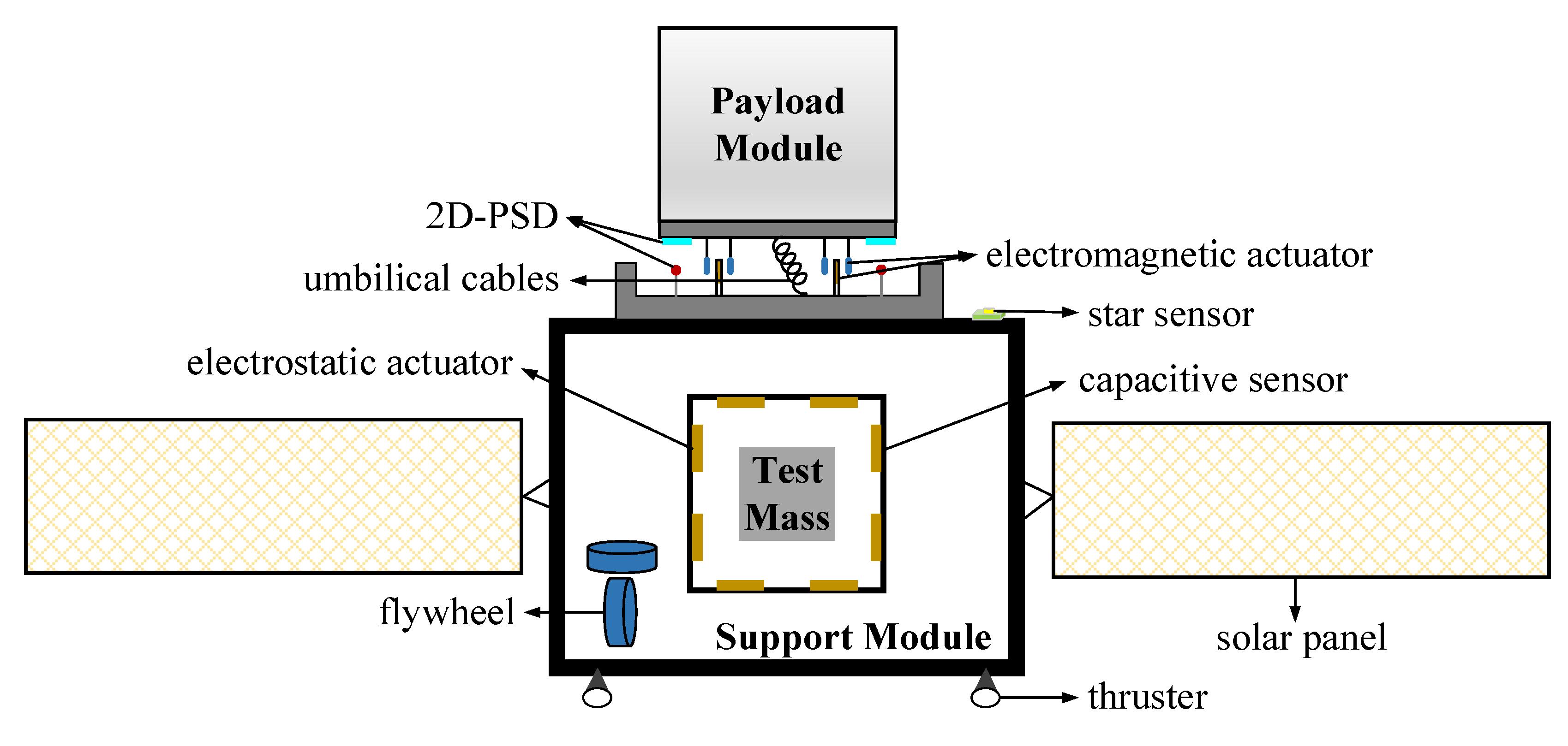
2. System Configuration

The proposed spacecraft architecture, which is based on the DFP spacecraft with umbilical cables, is illustrated in Figure 1. The improved DFP spacecraft is composed of a PM, an SM, and a TM. The PM that the payload is mounted on is levitated close to the SM through non-contact sensors and actuators. A bundle of umbilical cables for data, power, and fluid transfer comprises the only mechanical links between the PM and the SM. The TM, which is used to attenuate the disturbances to the SM in the low-frequency band, is suspended within the SM. The SM is part of a novel satellite architecture, and it includes solar panels for power, thrusters for orbit control, and flywheels for attitude control.
Three sets of two-dimensional position-sensitive detectors (2D–PSDs) and three sets of two-dimensional output electromagnetic actuators are placed between the PM and the SM to isolate the PM from the disturbances of the SM [15]. The 2D–PSD consists of a photosensitive surface mounted on the PM and a collimated light-emitting diode mounted on the SM. The 2D–PSDs are used to measure the position and orientation of the PM with respect to the SM. The two-dimensional output electromagnetic actuator is composed of permanent magnets mounted on the PM and two sets of orthogonal coils mounted on the SM. The two-dimensional output electromagnetic actuators are used to generate the required forces and torques. Given the fact that the two-dimensional output electromagnetic actuators only function when the coils and magnets are adjacent to each other, the free motion of the PM with respect to the SM must be restricted to ±10 mm in translation and ±35 mrad in rotation.
The TM can be a gold-platinum cube that is enclosed within a housing rigidly attached to the body of the SM [20]. Electrodes on the inner faces of the housing are used to measure the position and orientation of the TM with respect to the housing. The TM and the electrode housing essentially constitute an inertial sensor. When the TM falls freely through space under the influence of gravity alone, the distance of the electrode housing from the TM is changed and sensed by the capacitive sensors. The electrostatic actuators are used to generate the required forces and torques via the voltages applied to the electrodes. The free motion of the TM with respect to the SM is usually restricted to ±4 mm in translation and ±2 mrad in rotation.
The typical sensors and actuators of the improved DFP spacecraft are listed in Table 1. It should be noted that three degrees of freedom (DOF) of the TM translation are a result of the drag-free motion and cannot be measured. Therefore, 15 DOF can be measured or derived from the sensor raw data. The actuation of the SM motion is performed with thrusters and flywheels that provide actuation authority along all six DOF. Furthermore, the PM and the TM can be actuated along six DOF with an electromagnetic or electrostatic suspension system. In total, all 18 rigid body DOF of the improved DFP spacecraft can be actuated.

3. System Dynamics Modeling and Controller Design

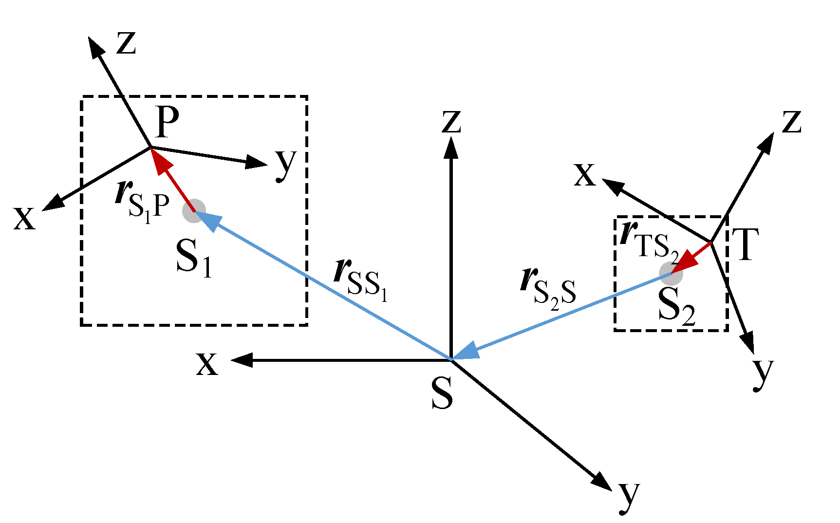
3.1. Dynamics Modeling

To establish the dynamics modeling of the improved DFP spacecraft, several coordinates are defined. The geocentric inertial coordinate system is denoted as Nxyz, and the orbit reference coordinate system is denoted as Oxyz. The Payload–Module-fixed coordinate system denoted as Pxyz, the Support–Module-fixed coordinate system denoted as Sxyz, and the Test–Mass-fixed coordinate system denoted as Txyz are fixed on the PM, the SM, and the TM, respectively.
Based on the Newton–Euler method, the nonlinear dynamics model of the improved DFP spacecraft can be expressed as
m S r ¨ NS = F S _ Gra + F S _ Thr + F S _ Umb + F S _ Mag + F S _ Ele + F S _ Vib + F S _ Ext m P r ¨ NP = F P _ Gra + F P _ Umb + F P _ Mag + F P _ Vib + F P _ Ext m T r ¨ NT = F T _ Gra + F T _ Ele + F T _ Vib + F T _ Ext I S α S N + ω S N × ( I S ω S N ) = M S _ Gra + M S _ Fly + M S _ Umb + M S _ Mag + M S _ Ele + M S _ Vib + M S _ Ext I P α P N + ω P N × ( I P ω P N ) = M P _ Gra + M P _ Umb + M P _ Mag + M P _ Vib + M P _ Ext I T α T N + ω T N × ( I T ω T N ) = M T _ Gra + M T _ Ele + M T _ Vib + M T _ Ext
where the subscripts S, P, and T represent the SM, the PM, and the TM, respectively, and are replaced by the X below; m X and I X are the mass and the inertia matrixes, respectively; r NX is the position vector, and r NX is the moduli of r NX ; r ¨ NX is the second-order derivative with respect to Nxyz; α X N and ω X N are the attitude angular acceleration and velocity with respect to Nxyz, respectively; F X _ Thr is the force generated by thrusters; M X _ Fly is the torque generated by flywheels; F X _ Gra , F X _ Umb , F X _ Mag , F X _ Ele , F X _ Vib , F X _ Ext are the forces, M X _ Gra , M X _ Umb , M X _ Mag , M X _ Ele , M X _ Vib , M X _ Ext are the torques generated by the Earth, the umbilical cables, the electromagnetic actuators, the electrostatic actuators, the local disturbances, and the external disturbances, respectively.
Since the cubic TM is used to provide a high-precision inertial reference and is shielded by the SM, the disturbances F T _ Vib , F T _ Ext , M T _ Gra , M T _ Vib , and M T _ Ext can be negligible. In addition, based on Newton’s law of action and reaction, the corresponding conditions can be expressed as
F S _ Umb = F P _ Umb ,   F S _ Mag = F P _ Mag ,   F S _ Ele = F T _ Ele , M S _ Umb = M P _ Umb ,   M S _ Mag = M P _ Mag ,   M S _ Ele = M T _ Ele , F T _ Vib = 0 3 × 1 ,   F T _ Ext = 0 3 × 1 ,   M T _ Gra = 0 3 × 1 ,   M T _ Vib = 0 3 × 1 ,   M T _ Ext = 0 3 × 1
where 0 3 × 1 represents a zero vector with three rows and one column.
According to the compound law of motion of a grid body and Equation (1), the relative motion of the improved DFP spacecraft can be written as
r ¨ SP | S + 2 ω S N × r ˙ SP | S + α S N × r SP + ω S N × ( ω S N × r SP )   = F P _ Gra / m P F S _ Gra / m S + F P _ Umb ( 1 / m P + 1 / m S ) + F P _ Mag ( 1 / m P + 1 / m S )         F S _ Thr / m S F S _ Ele / m S + F P _ Vib / m P F S _ Vib / m S + F P _ Ext / m P F S _ Ext / m S I P ( α S N + α P S + ω S N × ω P S ) + ( ω S N + ω P S ) × [ I P ( ω S N + ω P S ) ]   = M P _ Gra + M P _ Umb + M P _ Mag + M P _ Vib + M P _ Ext r ¨ TS | T + 2 ω T N × r ˙ TS | T + α T N × r TS + ω T N × ( ω T N × r TS )   = F S _ Gra / m S F T _ Gra / m T + F S _ Thr / m S + F S _ Umb / m S + F S _ Mag / m S         + F S _ Ele ( 1 / m S + 1 / m T ) + F S _ Vib / m S + F S _ Ext / m S I S ( α T N + α S T + ω T N × ω S T ) + ( ω T N + ω S T ) × [ I S ( ω T N + ω S T ) ]   = M S _ Gra + M S _ Fly + M S _ Umb + M S _ Mag + M S _ Ele + M S _ Vib + M S _ Ext
where r SP is the relative motion of the PM with respect to the SM; r ˙ SP | S and r ¨ SP | S are the one-order and second-order derivatives with respect to Sxyz, respectively; ω P S and α P S are the attitude angular velocity and the acceleration of the PM with respect to the SM, respectively; r TS is the relative motion of the SM with respect to the TM; r ˙ TS | T and r ¨ TS | T are the first-order and second-order derivatives with respect to Txyz, respectively; and ω S T and α S T are the attitude angular velocity and the acceleration of the PM with respect to the SM, respectively.
The linearization of the nonlinear dynamics model is established to simplify the dynamics analysis and the controller design. The linear dynamics equation can be expressed as
[ θ ¨ T N r ¨ S 1 P | S θ ¨ P S r ¨ TS 2 | T θ ¨ S T ] = [ 0 3 × 3 E 3 × 3 0 3 × 3 0 3 × 3 0 3 × 3 0 3 × 3 0 3 × 3 0 3 × 3 E 3 × 3 0 3 × 3 E 3 × 3 r SS 1 × 0 3 × 3 0 3 × 3 0 3 × 3 E 3 × 3 0 3 × 3 E 3 × 3 E 3 × 3 r TS 2 × 0 3 × 3 0 3 × 3 E 3 × 3 0 3 × 3 0 3 × 3 E 3 × 3 0 3 × 3 0 3 × 3 0 3 × 3 E 3 × 3 ] [ a T α T a P α P a S α S ] a S = ( F S _ Gra + F S _ Thr + F S _ Umb + F S _ Mag + F S _ Ele + F S _ Vib + F S _ Ext ) / m S a P = ( F P _ Gra + F P _ Umb + F P _ Mag + F P _ Vib + F P _ Ext ) / m P a T = ( F T _ Gra + F T _ Ele + F T _ Vib + F T _ Ext ) / m T α S = I S 1 ( M S _ Gra + M S _ Fly + M S _ Umb + M S _ Mag + M S _ Ele + M S _ Vib + M S _ Ext ) α P = I P 1 ( M P _ Gra + M P _ Umb + M P _ Mag + M P _ Vib + M P _ Ext ) α T = I T 1 ( M T _ Gra + M T _ Ele + M T _ Vib + M T _ Ext )
where the points S 1 and S 2 , fixed on the SM, as shown in Figure 2, are the geometric center of the motion space of the PM (±10 mm, ±35 mrad) and the motion space of the TM (±4 mm, ±2 mrad), respectively. θ P S and θ S T are the relative attitude angles of the PM with respect to the SM and of the SM with respect to the TM, respectively; and a X and α X are the acceleration caused by all of the forces and the attitude angular accelerations caused by all of the torques, respectively. 0 3 × 3 and E 3 × 3 represent the 3 × 3 zero matrix and identity matrix, respectively.

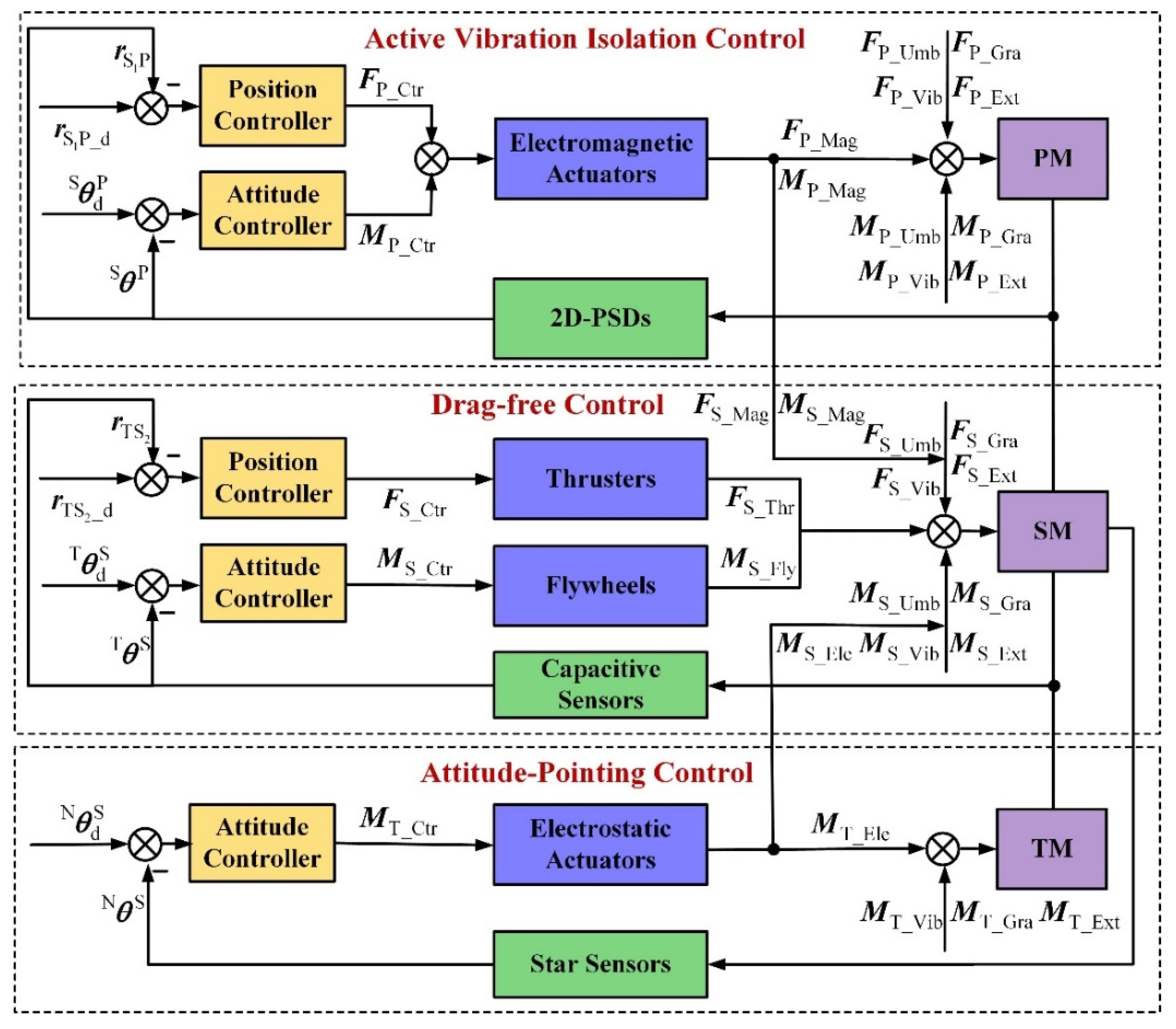
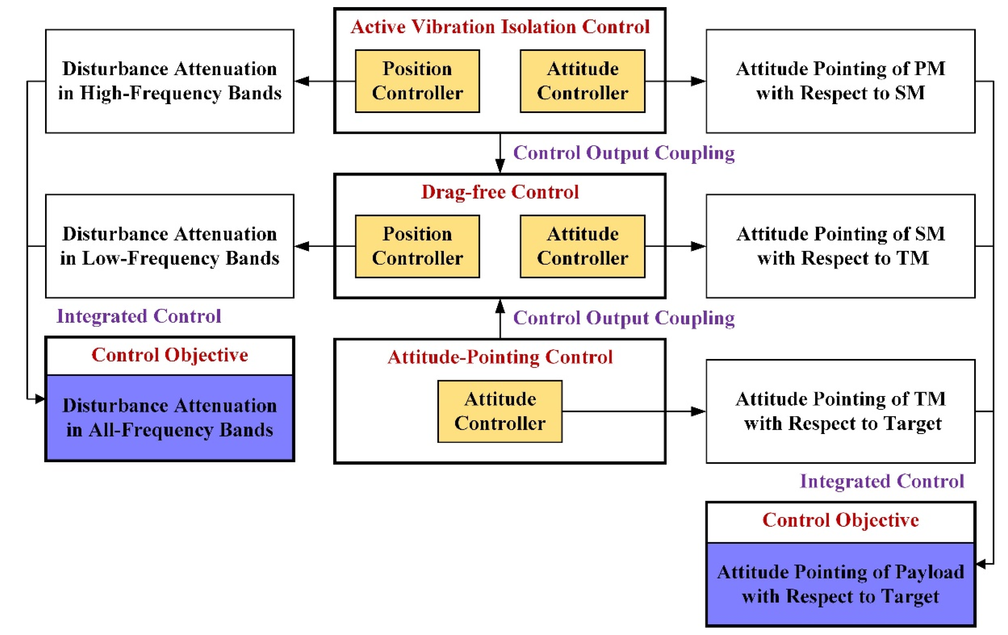
3.2. Controller Design

The control scheme shown in Figure 3 is the control algorithm design for the improved DFP spacecraft, where the F P _ Ctr and M P _ Ctr generated by the electromagnetic actuators are the control forces and torques of the PM, respectively, the r S 1 P and θ P S measured with the 2D–PSDs are the relative motions of the PM with respect to the SM, and the r S 1 P _ d and θ d P S are the desired relative motions (the objectives of the control system). The F S _ Ctr generated by the thrusters and the M S _ Ctr generated by the flywheels are the control forces and torques of the SM, respectively, the r TS 2 and θ S T measured by the capacitive sensors are the relative motions of the SM with respect to the TM, and the r TS 2 _ d and θ d S T are the desired relative motions. The M T _ Ctr generated by the electrostatic actuators refers to the control torques of the TM, the θ S N measured by the star sensors is the relative attitude angle of the SM with respect to Nxyz, and θ d S N is the desired relative motion.
Thus, in total, there are 15 DOF to be controlled that can be subdivided into three interconnected control loops:
  • An active vibration isolation control loop is used to isolate the PM from disturbances in the high-frequency bands, prevent a collision between the PM and the SM, and control the PM to track the attitude of the SM;
  • A drag-free control loop is used to isolate the SM from disturbances in the low-frequency bands, prevent the collision between the SM and the TM, and control the SM to track the attitude of the TM;
  • An attitude-pointing control loop is used to control the TM to track the desired attitude, which is determined by the pointing requirement of the payload.
The control system of the improved DFP spacecraft should be co-designed, as shown in Figure 4. There are two control objectives. One is to isolate the payload mounted on the PM from a disturbance in all frequency bands, and the other is to achieve the payload pointing to the target. The payload can be isolated from disturbances in all of the frequency bands by the active vibration isolation control and the drag-free control. The pointing requirement of the payload can be satisfied with the attitude-pointing control of the TM with respect to the target, the attitude-pointing control of the PM with respect to the SM, and the attitude-pointing control of the SM with respect to the TM. In addition, the electromagnetic forces and torques controlling the PM and the electrostatic torques controlling the TM produce reaction disturbances to the SM at the same time. Therefore, the drag-free control of the SM employs feedforward compensation to eliminate the coupling disturbances.
Based on the Proportional–Integral–Derivative (PID) control algorithm, the integrated control system for the improved DFP spacecraft is designed as
F P _ Ctr = K P _ Pr ( r S 1 P _ d r S 1 P ) + K P _ Dr ( r ˙ S 1 P _ d | S r ˙ S 1 P | S ) + K P _ Ir ( r S 1 P _ d r S 1 P ) d t M P _ Ctr = K P _ P θ ( θ d P S θ P S ) + K P _ D θ ( θ ˙ d P S | S θ ˙ P S | S ) + K P _ I θ ( θ d P S θ P S ) d t F S _ Ctr = K S _ Pr ( r TS 2 _ d r TS 2 ) + K S _ Dr ( r ˙ TS 2 _ d | S r ˙ TS 2 | S ) + K S _ Ir ( r TS 2 _ d r TS 2 ) d t + F P _ Ctr M S _ Ctr = K S _ P θ ( θ d S T θ S T ) + K S _ D θ ( θ ˙ d S T | S θ ˙ S T | S ) + K S _ I θ ( θ d S T θ S T ) d t + M P _ Ctr + M T _ Ctr M T _ Ctr = K T _ P θ ( θ d S N θ S N ) + K T _ D θ ( θ ˙ d S N | N θ ˙ S T | N ) + K T _ I θ ( θ d S N θ S N ) d t
where K X _ Pr , K X _ Dr , and K X _ Ir are the PID parameters of the position controller; and K X _ P θ ; K X _ D θ , and K X _ I θ are the PID parameters of the attitude position controller. Therefore, the control forces and torques acting on the PM, the SM, and the TM can be expressed as
F P _ Act = F P _ Mag = K P _ Pr ( r S 1 P _ d r S 1 P ) + K P _ Dr ( r ˙ S 1 P _ d | S r ˙ S 1 P | S ) + K P _ Ir ( r S 1 P _ d r S 1 P ) d t M P _ Act = F P _ Mag = K P _ P θ ( θ d P S θ P S ) + K P _ D θ ( θ ˙ d P S | S θ ˙ P S | S ) + K P _ I θ ( θ d P S θ P S ) d t F S _ Act = F S _ Thr + F S _ Mag + F S _ Ele = K S _ Pr ( r TS 2 _ d r TS 2 ) + K S _ Dr ( r ˙ TS 2 _ d | S r ˙ TS 2 | S ) + K S _ Ir ( r TS 2 _ d r TS 2 ) d t M S _ Act = M S _ Fly + M S _ Mag + M S _ Ele = K S _ P θ ( θ d S T θ S T ) + K S _ D θ ( θ ˙ d S T | S θ ˙ S T | S ) + K S _ I θ ( θ d S T θ S T ) d t M T _ Ctr = M T _ Ele = K T _ P θ ( θ d S N θ S N ) + K T _ D θ ( θ ˙ d S N | N θ ˙ S T | N ) + K T _ I θ ( θ d S N θ S N ) d t
The key task is to determine the PID parameters to achieve high-level disturbance attenuation performance and pointing accuracy. Liu and Gao [21] provided a calculation method for the PID parameters, which is expressed as
k p = ω n 2 2 + 2 ω n 1 ω n 2 ζ 2 k d = ω n 1 ω n 2 2 k i = ω n 1 + 2 ω n 2 ζ 2
where k p , k d , and k i are the PID parameters corresponding to unit mass or inertia for each DOF, and ω n 1 , ω n 2 , and ζ 2 are some typical elements that determine the disturbance isolation performance.
Since the active vibration isolation technology can attenuate the disturbances above the critical frequency, the PID parameters of the position controller in the active vibration isolation control loop should be small. In contrast, since the drag-free control technology can attenuate the disturbances below the critical frequency, the PID parameters of the position controller in the drag-free control loop need to be large. To improve the pointing accuracy, the PID parameters of the attitude controller in the attitude-pointing control loop, active vibration isolation control loop, and drag-free control loop need to be large.

4. Numerical Simulations

Numerical simulations are conducted to analyze the performance enhancement of the improved DFP spacecraft and to verify the effectiveness of the integrated control algorithm. The forces and torques caused by the gravitational attraction, solar radiation pressure, atmospheric drag, umbilical cables, and structural vibrations are added to the dynamic integration. To clearly analyze the control performance of the integrated controller of the improved DFP spacecraft, the uncertainties of the sensors and actuators are not considered in this study. Some simulation conditions are listed in Table 2 and Table 3.

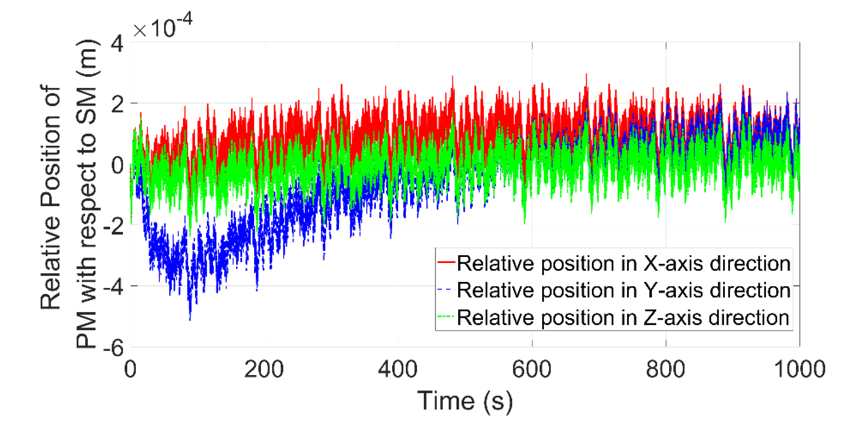
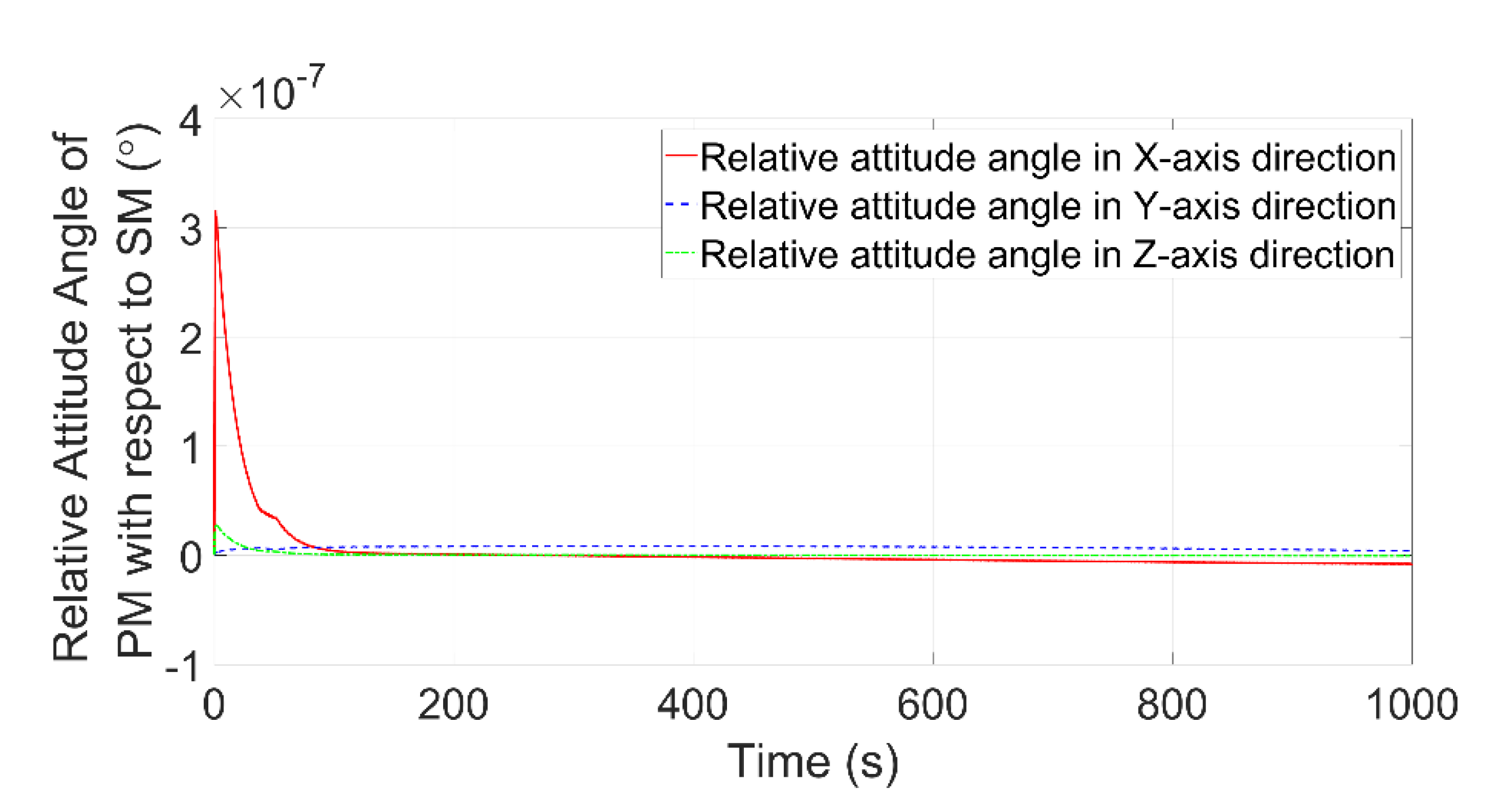
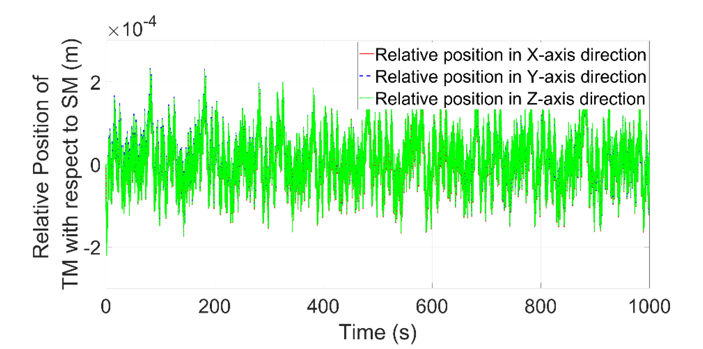
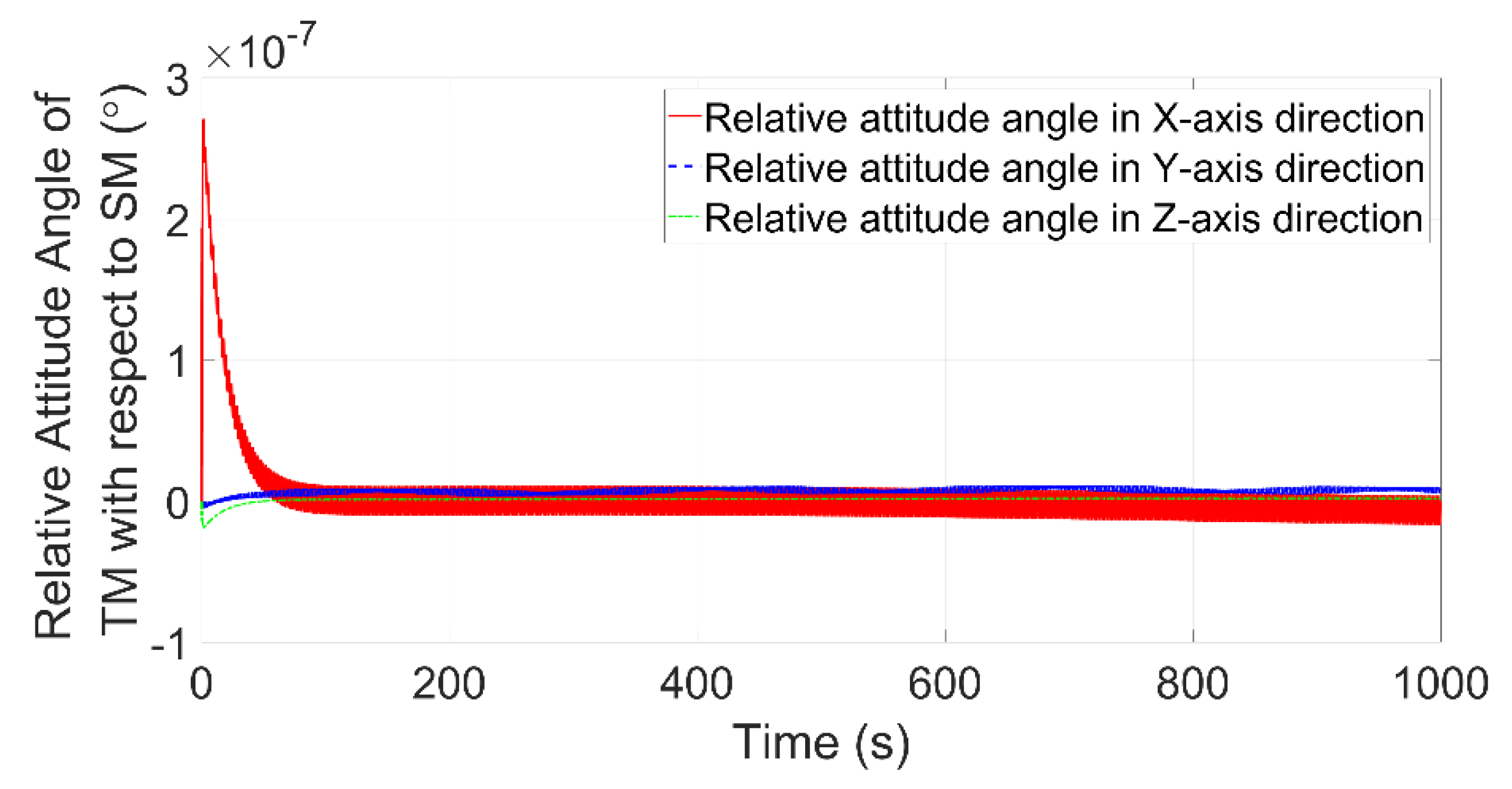
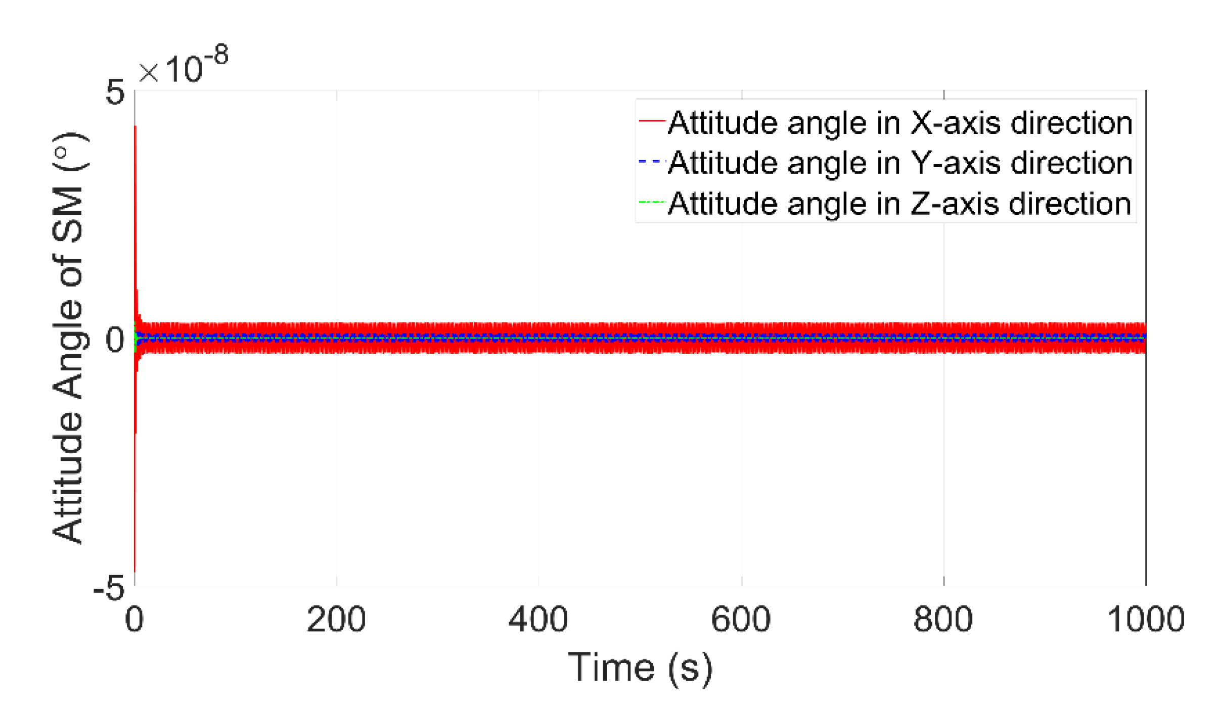
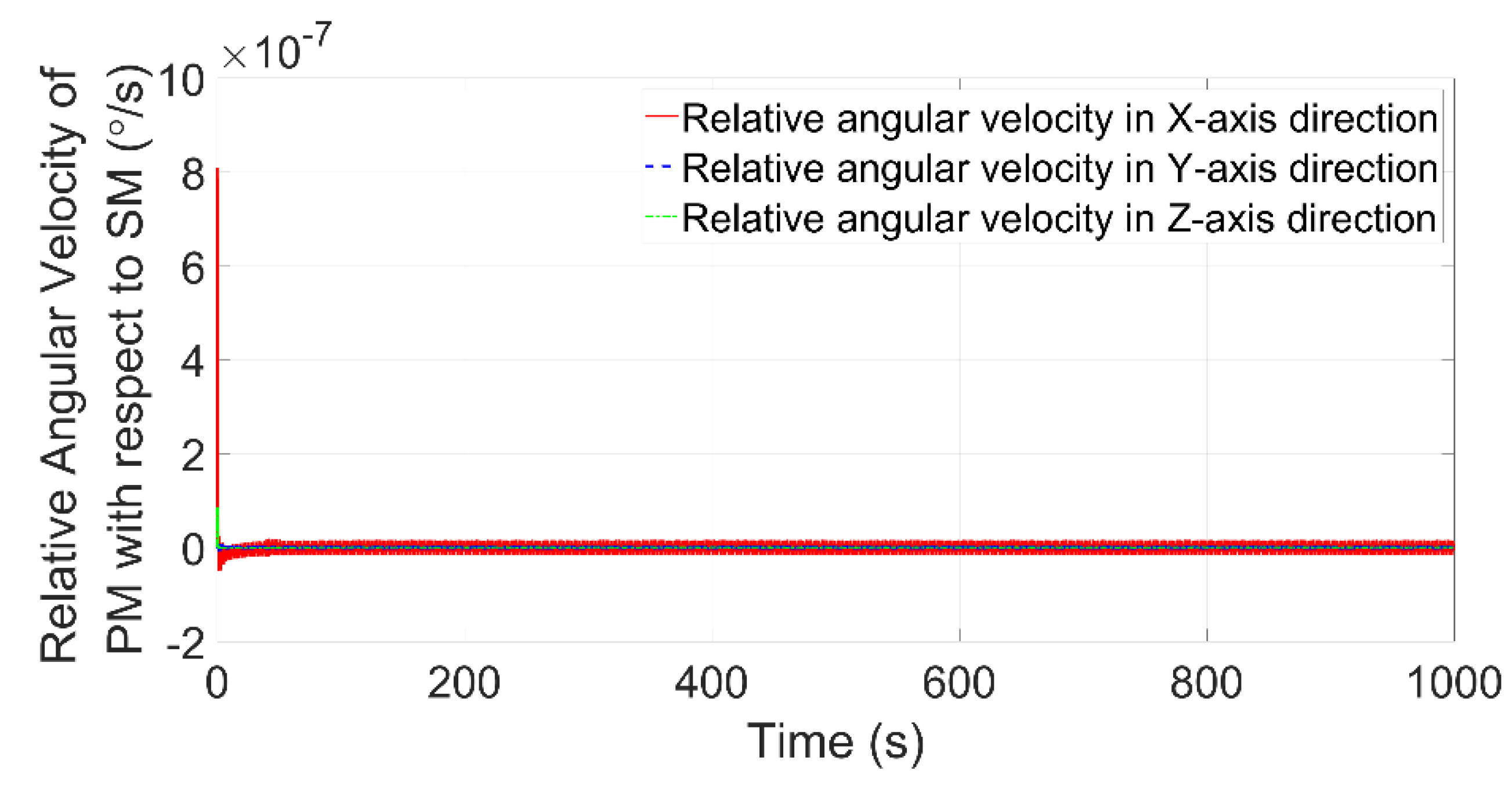
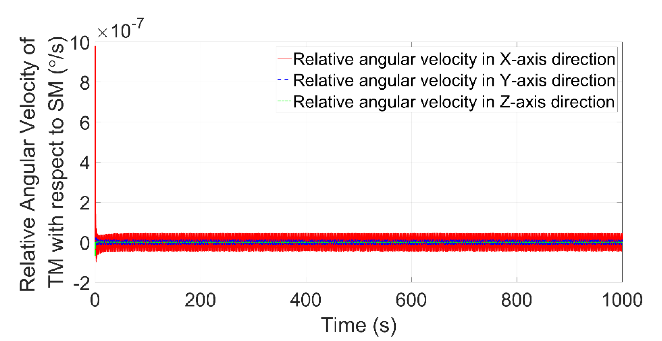
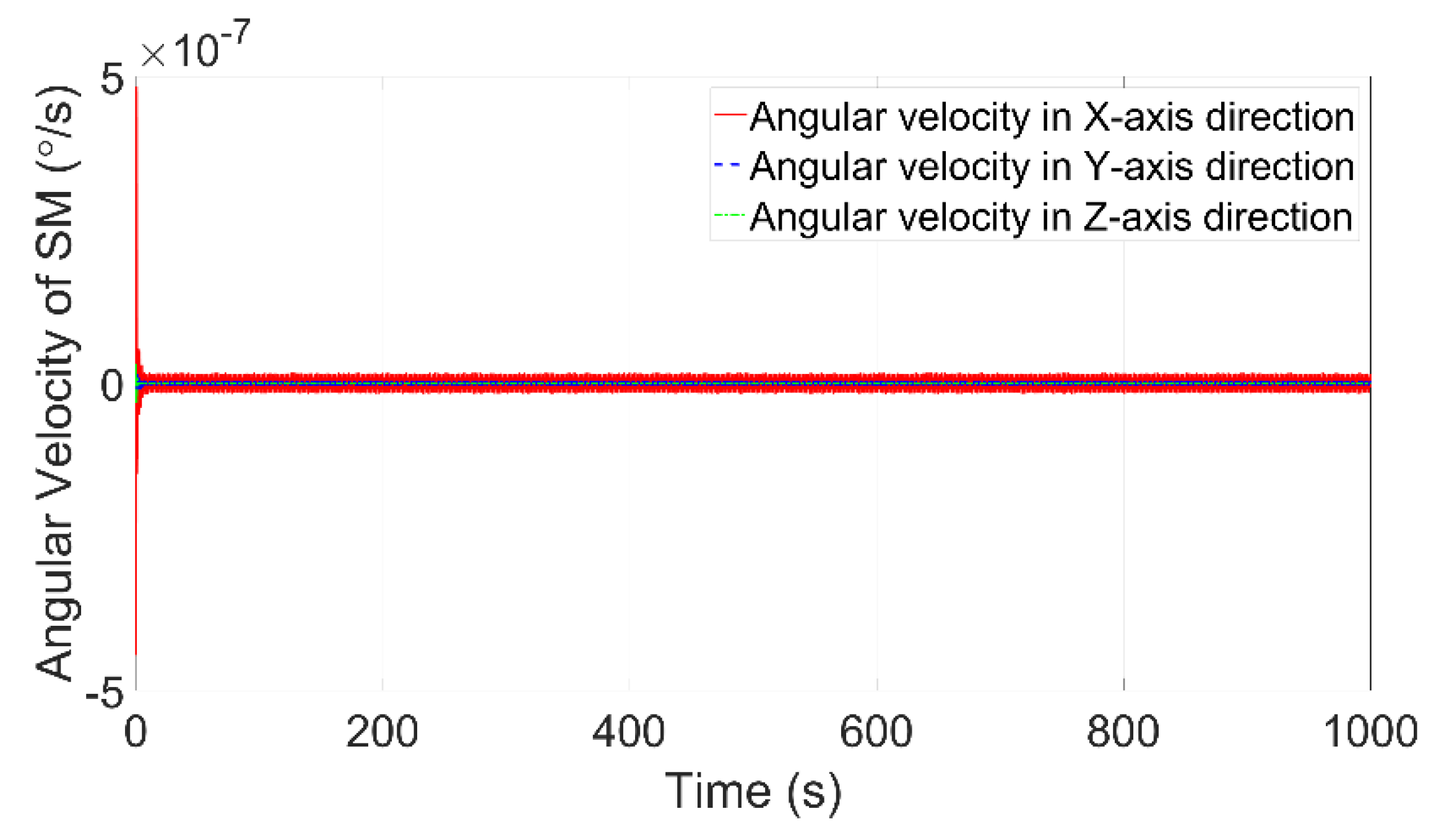
4.1. Stability of Integrated Control

The stability of the integrated control system is determined by the controller parameters. The PID controller parameters calculated according to Equation (7) can ensure the stability of the control system.
Figure 5 and Figure 6 depict the centroid position and the attitude angle of the PM with respect to the SM. These two figures show the stability of the active vibration isolation control loop when the spatial constraints of ±10 mm and ±35 mrad between the PM and SM are satisfied.
Figure 7 and Figure 8 depict the centroid position and attitude angle of the TM with respect to the SM. These two figures show the stability of the drag-free control loop when the spatial constraints of ±4 mm and ±2 mrad between the TM and SM are satisfied.
Figure 9 depicts the attitude angle of the SM, which shows the stability of the attitude-pointing control loop.
Figure 5, Figure 6, Figure 7, Figure 8 and Figure 9 show the stability of the integrated control algorithm of the improved DFP spacecraft and the satisfaction of the spatial constraints.

4.2. Pointing Accuracy and Stability

The payload pointing to the target is achieved indirectly. In the integrated control system, the TM is controlled to point to the target, the SM is controlled to track the attitude of the TM, and the payload mounted on the PM is controlled to track the attitude of the SM. The high-level pointing accuracy and stability of the payload are realized by the integrated control of the PM, SM, and TM.
Figure 9 shows that the pointing accuracy of the SM is better than 10−8°, and Figure 5 shows that the attitude angle of the PM with respect to the SM is smaller than 10−7°. Therefore, the pointing accuracy of the PM is about 10−7°. Figure 10, Figure 11 and Figure 12 show the attitude angular velocity of the PM with respect to the SM, that of the TM with respect to the SM, and that of the SM. The pointing stability of the PM is about 10−7°/s. These simulation results show that the integrated control algorithm of the improved DFP spacecraft can provide high-level pointing accuracy and stability for the payload in the PM.

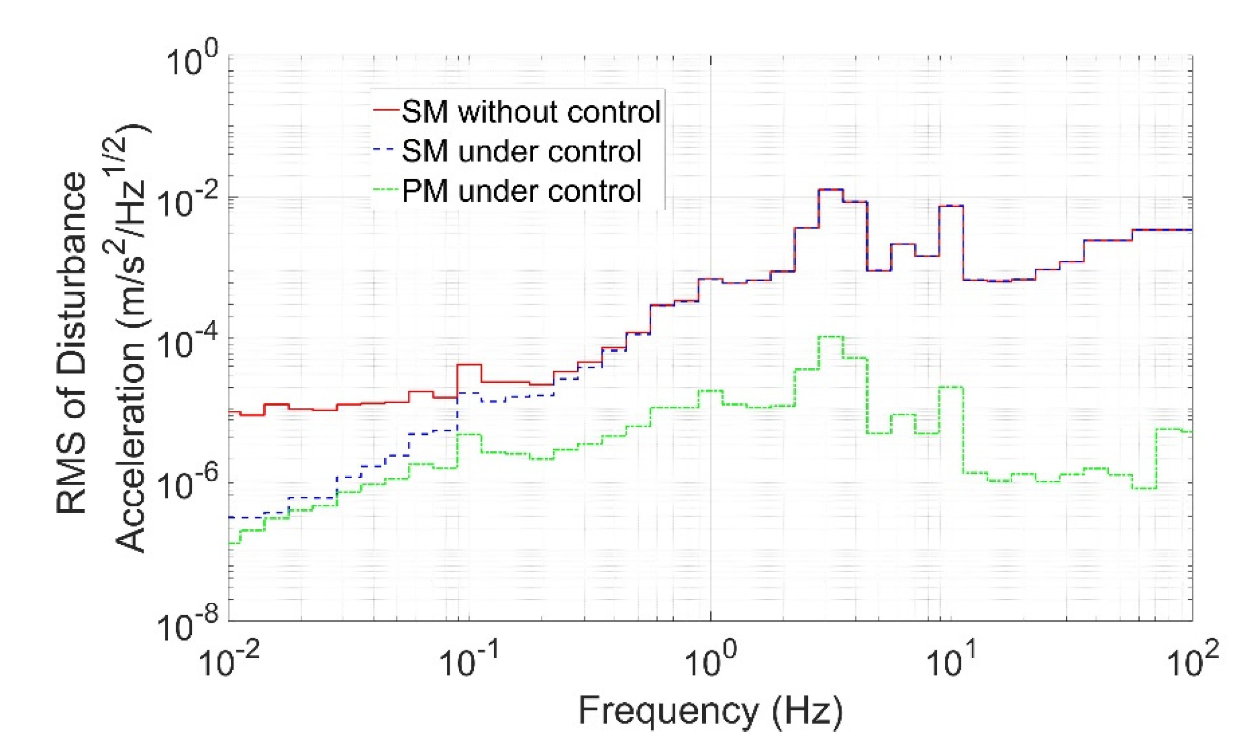
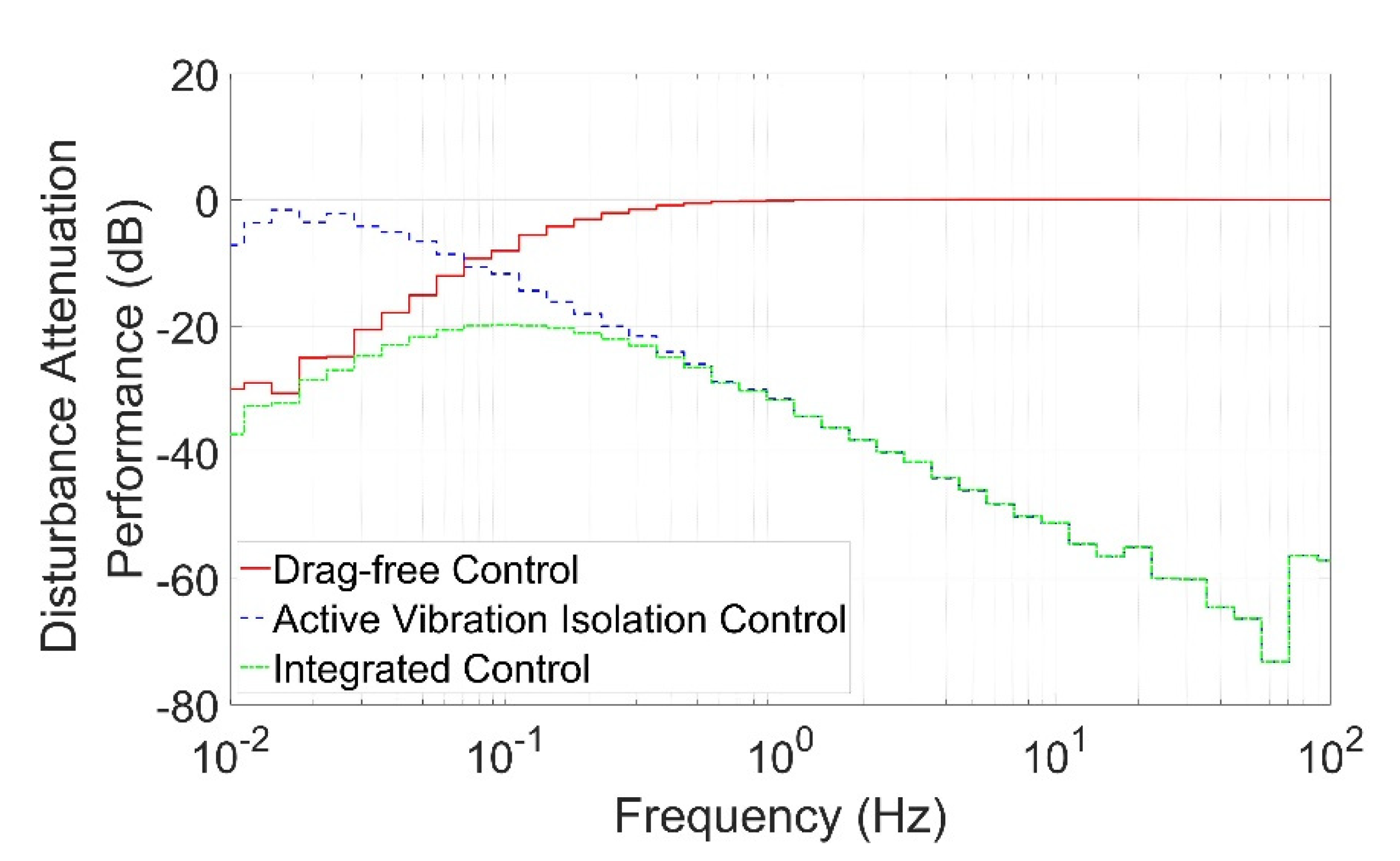
4.3. Disturbance Attenuation Performance

In the DFP spacecraft, the high-frequency disturbances of the payload mounted on the PM are attenuated by active vibration isolation control, but the low-frequency disturbances cannot be attenuated due to the umbilical cables. In the improved DFP spacecraft, the low-frequency disturbances of the SM are attenuated by drag-free control, which means that the low-frequency disturbances of the payload transmitted through the umbilical cables are attenuated. Therefore, the payload can be isolated from disturbances in all of the frequency bands by the active vibration isolation control loop and the drag-free control loop in the integrated control system.
The disturbance acceleration in the frequency domain is expressed in terms of the root mean square (RMS) per one-third octave band. Figure 13 shows the disturbance acceleration of the SM without control, the SM under control, and the PM under control. The disturbance acceleration of the SM without control is equivalent to the disturbance acceleration of the SM in the novel DFP spacecraft (without the TM). The disturbance acceleration of the SM under control represents the disturbance acceleration of the SM with the application of drag-free control in the improved DFP spacecraft. Compared with the disturbance acceleration of the SM without control, the disturbance acceleration of the SM under control is attenuated in the low-frequency bands, as expected. As the low-frequency disturbances of the SM under control are small, the disturbances transmitted to the PM through the umbilical cables are also small. The disturbance acceleration of the PM under control is obviously better than the disturbance acceleration of the SM without control in all of the frequency bands, which verifies the effectiveness of the improved DFP spacecraft and the integrated control algorithm. The disturbance attenuation performance is calculated as shown in Figure 14. The disturbance attenuation performance of the active vibration isolation control is equivalent to the control performance of the novel DFP spacecraft, and the disturbances in the low-frequency band cannot be attenuated. With the drag-free control in the improved DFP spacecraft, the disturbance attenuation performance of the integrated control is better than −20 dB in all of the frequency bands, which means the disturbances at any frequency are attenuated by at least one order of magnitude.

5. Conclusions

The improved DFP spacecraft is designed to overcome the disturbances caused by the umbilical cables connecting the PM and the SM. The TM is added to the improved DFP spacecraft, and drag-free control technology is applied to isolate disturbances on the SM in the low-frequency band. The configuration of the improved DFP spacecraft and its sensors and actuators are introduced. The improved DFP spacecraft consists of the PM, the SM, and the TM. The PM is levitated close to the SM by the electromagnetic actuators, while the TM is suspended inside the SM by the electrostatic actuators.
The dynamics model of the improved DFP spacecraft is established, including the nonlinear dynamics equation and the linear dynamics equation. The integrated control of the improved DFP spacecraft is designed to enhance the pointing accuracy and disturbance attenuation performance. The control system consists of three interconnected control loops, which are the active vibration isolation control loop, the drag-free control loop, and the attitude-pointing control loop. Based on the integrated control algorithm, the PM can be isolated from disturbances in all of the frequency bands, and the pointing requirement of the payload can be achieved. The numerical simulations show that the pointing accuracy and the pointing stability are about 10−7° and 10−7°/s, respectively, and the disturbance attenuation performance is better than −20 dB in all of the frequency bands. The control performance of the improved DFP spacecraft is obviously enhanced by the integrated control system. This work lays the foundation for the development of improved DFP spacecraft, which has significant application value.

Author Contributions

Conceptualization, T.J., G.K. and J.C.; Formal analysis, X.Z. and Z.Z.; Investigation, L.L. and F.L.; Methodology, T.J.; Software, T.J.; Validation, T.J., S.J. and J.Y.; Writing—original draft, T.J.; Writing—review & editing, T.J., G.K. and J.C. All authors have read and agreed to the published version of the manuscript.

Funding

This research received no external funding.

Conflicts of Interest

The authors declare no conflict of interest.

References

  1. Nordt, A.; Dewell, L. Non-contact vibration isolation and precision pointing for large optical telescopes. Bull. Am. Astron. Soc. 2019, 51, 249. [Google Scholar]
  2. Bauer, F.H.; Hyde, T.T.; Maghami, P.G. Precision pointing for the laser interferometer space antenna (LISA) mission. In Proceedings of the 2003 AAS Guidance and Control Conference, Breckenridge, CO, USA, 5–9 February 2003. [Google Scholar]
  3. Dewell, L.; Pedreiro, N.; Blaurock, C.; Liu, K.C.; Alexander, J.; Levine, M. Precision telescope pointing and spacecraft vibration isolation for the Terrestrial Planet Finder Coronagraph. In Proceedings of the SPIE Optics and Photonics, San Diego, CA, USA, 31 July–4 August 2005; p. 589902. [Google Scholar] [CrossRef]
  4. Chen, C.C.; Hemmati, H.; Biswas, A.; Ortiz, G.; Farr, W.; Pedreiro, N. Simplified lasercom system architecture using a disturbance-free platform. In Proceedings of the Lasers and Applications in Science and Engineering, San Jose, CA, USA, 21–26 January 2006; p. 610505. [Google Scholar] [CrossRef]
  5. Li, L.; Yuan, L.; Wang, L.; Zheng, R.; Wu, Y.P.; Wang, X.Y. Recent advances in precision measurement & pointing control of spacecraft. Chin. J. Areonaut. 2021, 34, 191–209. [Google Scholar] [CrossRef]
  6. Shi, J.F.; Cheng, P.F.; Yuan, H.; Ren, G.R.; Wang, W.; Fan, X.W.; Li, Z.G. Analysis and verification of effect of micro-vibration on space photoelectric payload imaging. Acta Opt. Sin. 2019, 39, 0520001. [Google Scholar] [CrossRef]
  7. Komatsu, K.; Uchida, H. Microvibration in spacecraft. Mech. Eng. Rev. 2014, 1, SE0010. [Google Scholar] [CrossRef]
  8. Cui, Y.F.; Liu, J.Y.; He, H.Y.; Yin, H. Influence of micro vibration on radiation quality of high resolution TDICCD images. Chin. Space Sci. Techn. 2018, 38, 28–35. [Google Scholar] [CrossRef]
  9. Pedreiro, N. Spacecraft architecture for disturbance-free payload. J. Guid. Control Dyn. 2003, 26, 794–804. [Google Scholar] [CrossRef]
  10. Trankle, T.; Pedreiro, N.; Andersen, G. Disturbance free payload flight system analysis and simulation methods. In AIAA Guidance, Navigation, and Control Conference and Exhibit; American Institute of Aeronautics and Astronautics: Reston, VA, USA, 2005. [Google Scholar]
  11. Zhang, W.; Zhai, Y.B.; Liao, H.; Zhao, H.B. Design of an active-quiet isolated and master-slave coordination controlled dual-super satellite platform. Aerosp. Shanghai 2014, 31, 7–11. [Google Scholar] [CrossRef]
  12. Zhao, T.S.; Zhang, J.Y.; Wu, D.Y.; Luo, R.Z. Dynamic modeling and control method of dual-body satellite. J. Phys. Conf. Ser. 2021, 2029, 012006. [Google Scholar] [CrossRef]
  13. Regehr, M. Analysis of a Near-Free-Floating Vibration Isolation Platform. In Interplanetary Network Progress Report; NASA: Washington, DC, USA; Jet Propulsion Laboratory: Pasadena, CA, USA; California Institute of Technology: Pasadena, CA, USA, 2015; pp. 42–200. [Google Scholar]
  14. Edberg, D.L.; Wilson, B.W. Design and testing of reduced-stiffness umbilicals for space station microgravity isolation. J. Spacecr. Rockets 2001, 38, 563–568. [Google Scholar] [CrossRef]
  15. Liu, W.; Wang, S.Q. Microgravity performance evaluation for zero gravity robot in China’s Space Station. IEEE Aerosp. Electron. Syst. Mag. 2022, 37, 32–42. [Google Scholar] [CrossRef]
  16. Zhou, J.X.; Wang, Z.G.; Li, W.; Liu, L.; Deng, Y.F.; Zhao, Q. Modeling and pointing performance analysis of disturbance-free-payload system with flexible umbilical connection. IEEE Access 2019, 7, 109585–109596. [Google Scholar] [CrossRef]
  17. Yang, H.J.; Liu, L.; Liu, Y.; Li, X.G. Modeling and micro-vibration control of flexible cable for disturbance-free payload spacecraft. Microgravity Sci. Technol. 2021, 33, 46. [Google Scholar] [CrossRef]
  18. Pugh, G.E. Proposal for a satellite test of the coriolis predictions of general relativity. In Nonlinear Gravitodynamics: The Lense-Thirring Effect; Ruffini, R., Sigismondi, C., Eds.; World Scientific: Singapore, 2003; pp. 414–426. [Google Scholar]
  19. Hu, M.; Li, H.Y.; Zhou, Z.B. Drag-free control technology and its applications. Manned Spacefl. 2013, 19, 61–69. [Google Scholar] [CrossRef]
  20. Zanoni, C. Drag-Free Spacecraft Technologies: Criticalities in the Initialization of Geodesic Motion. Ph.D. Thesis, University of Trento, Trento, Italy, 2015. [Google Scholar]
  21. Liu, W.; Gao, Y. Drag-free control methods for space-based gravitational-wave detection. Sci. Sin. Phys. Mech. Astron. 2020, 50, 079503. [Google Scholar] [CrossRef]
Figure 1. Improved DFP spacecraft architecture. DFP, disturbance-free payload.
Aerospace 09 00571 g001
Figure 2. Coordinate systems and positional relationships.
Aerospace 09 00571 g002
Figure 3. Control scheme of the improved DFP spacecraft.
Aerospace 09 00571 g003
Figure 4. Relationship among the three control loops of the integrated control system.
Aerospace 09 00571 g004
Figure 5. Centroid position of the PM with respect to the SM. PM, payload module; SM, support module.
Aerospace 09 00571 g005
Figure 6. Attitude angle of the PM with respect to the SM.
Aerospace 09 00571 g006
Figure 7. Centroid position of the TM with respect to the SM. TM, test mass.
Aerospace 09 00571 g007
Figure 8. Attitude angle of the TM with respect to the SM.
Aerospace 09 00571 g008
Figure 9. Attitude angle of the SM.
Aerospace 09 00571 g009
Figure 10. Attitude angular velocity of the PM with respect to the SM.
Aerospace 09 00571 g010
Figure 11. Attitude angular velocity of the TM with respect to the SM.
Aerospace 09 00571 g011
Figure 12. Attitude angular velocity of the SM.
Aerospace 09 00571 g012
Figure 13. Disturbance acceleration of the improved DFP spacecraft.
Aerospace 09 00571 g013
Figure 14. Disturbance attenuation performance of the improved DFP spacecraft.
Aerospace 09 00571 g014
Table 1. Sensors and actuators of the improved DFP spacecraft.
ComponentInstallation PositionFunction
Sensor2D-PSDsBetween the PM and the SMMeasure the position and orientation of the PM with respect to the SM
Capacitive sensorsBetween the TM and the SMMeasure the position and orientation of the TM with respect to the SM
Star sensorsOn the SMMeasure the orientation of the SM with respect to the inertial space
ActuatorElectromagnetic actuatorsBetween the PM and the SMGenerate forces and torques acting on the PM and the SM
Electrostatic actuatorsBetween the TM and the SMGenerate forces and torques acting on the TM and the SM
ThrustersOn the SMGenerate forces acting on the SM
FlywheelsOn the SMGenerate torques acting on the SM
DFP, disturbance-free payload; 2D–PSDs, two-dimensional position-sensitive detectors; PM, payload module; SM, support module; TM, test mass.
Table 2. Simulation parameters of the improved DFP spacecraft.
NameMass (kg)Inertia (kg.m2)Size (m)
PM50 [ 3.71 0 0 0 3.71 0 0 0 32 ] 0.8 × 0.8 × 0.5
SM100 [ 11.33 0 0 0 11.33 0 0 0 100 ] 1 × 1 × 0.6
TM2 [ 7.05 × 10 4 0 0 0 7.05 × 10 4 0 0 0 7.05 × 10 4 ] 0.046 × 0.046 × 0.046
Table 3. Controller parameters of the improved DFP spacecraft.
NameValue
Vibration isolation control loopPosition controller ω n 1 = 2 π × 10 3 , ω n 2 = 2 π × 10 2 , ζ 2 = 1.2
Attitude controller ω n 1 = 2 π × 10 2 , ω n 2 = 2 π × 10 0 , ζ 2 = 1.2
Drag-free control loopPosition controller ω n 1 = 2 π × 10 3 , ω n 2 = 2 π × 10 1 , ζ 2 = 1.2
Attitude controller ω n 1 = 2 π × 10 2 , ω n 2 = 2 π × 10 0 , ζ 2 = 1.2
Attitude-pointing control loopAttitude controller ω n 1 = 2 π × 10 2 , ω n 2 = 2 π × 10 0 , ζ 2 = 1.2
Publisher’s Note: MDPI stays neutral with regard to jurisdictional claims in published maps and institutional affiliations.

