
Self-Organizing Control-Loop Recovery for Predictive Networked Formation Control of Fractionated Spacecraft

Abstract
:1. Introduction
- It should keep the work load distribution in the intra- and inter- satellite node network optimal while still maintaining the required closed-loop performance of the original control process.
- It needs to keep the computational burden of the distribution low and scale with the number of possible node choices.
- In should allow multiple optimization objectives to take the heterogeneity of the nodes into account
- 1.
- Robust detection of controller loss/failure
- 2.
- Intelligent re-assignment of controller responsibilities by performing a distributed multi-objective optimization using a robust control task auctioning procedure
2. Materials and Methods
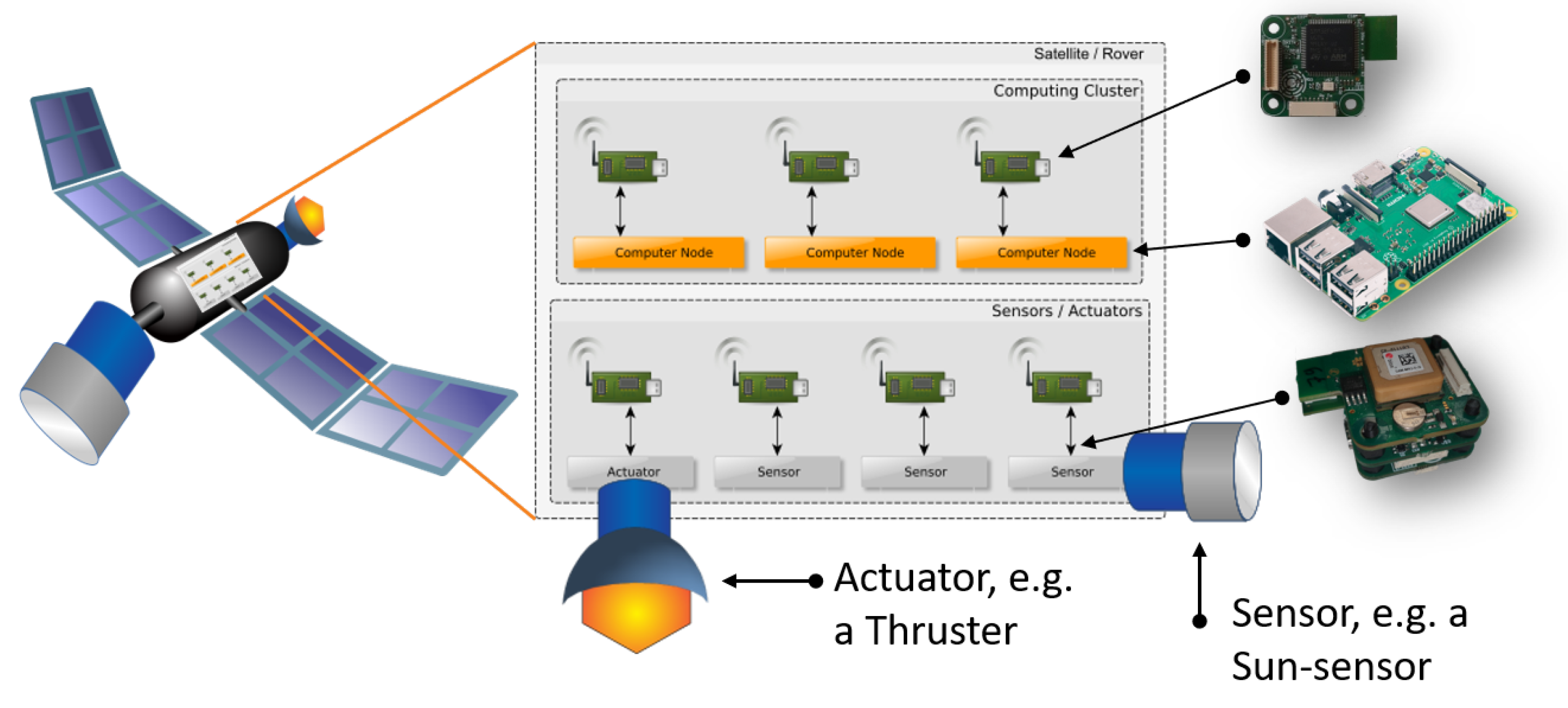
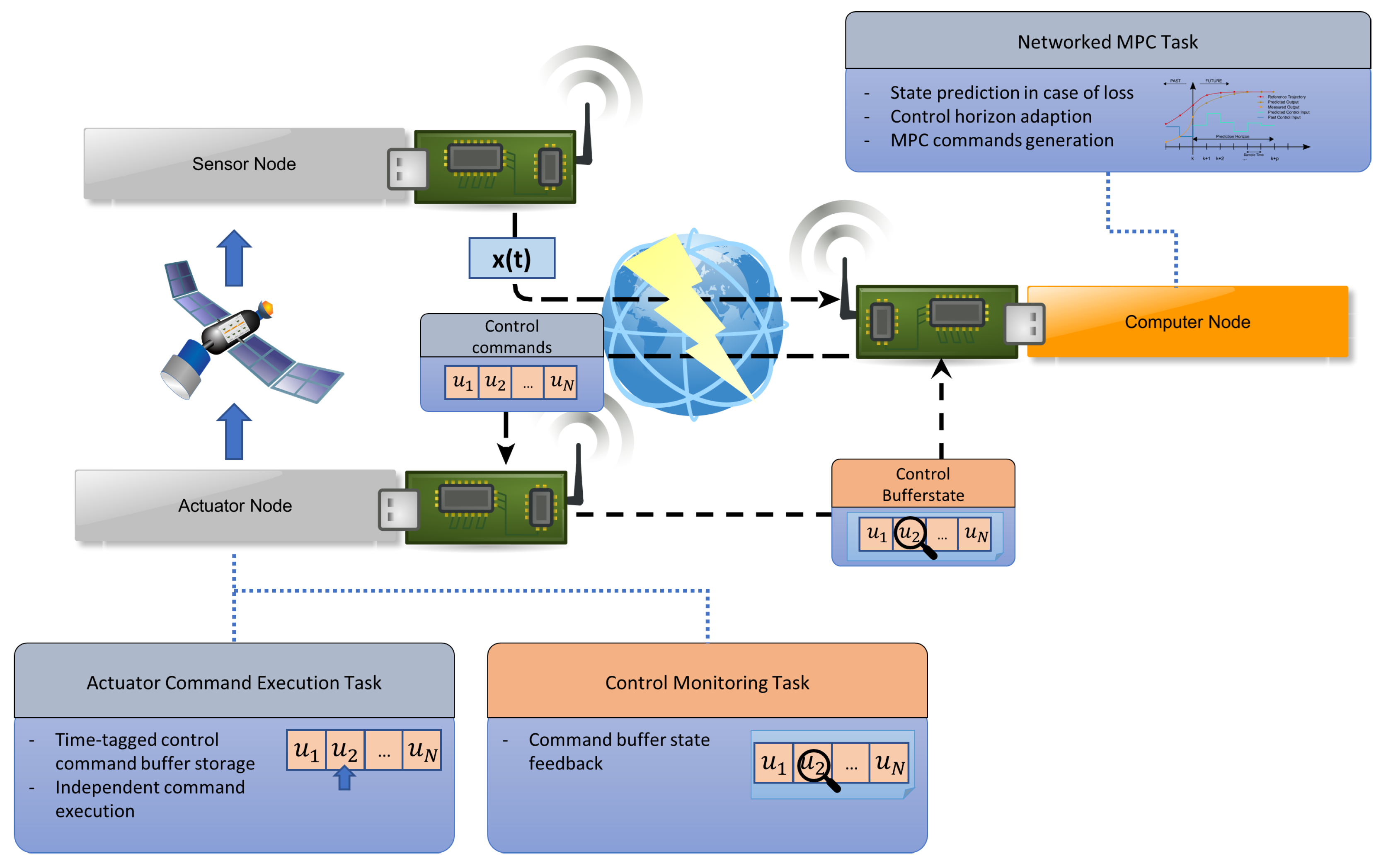
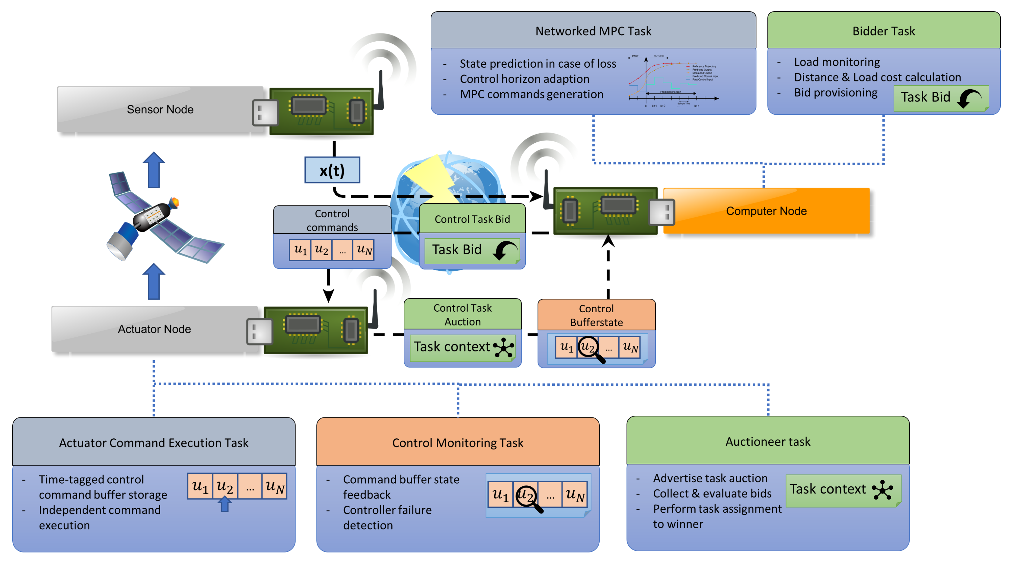
2.1. SW Support Architecture
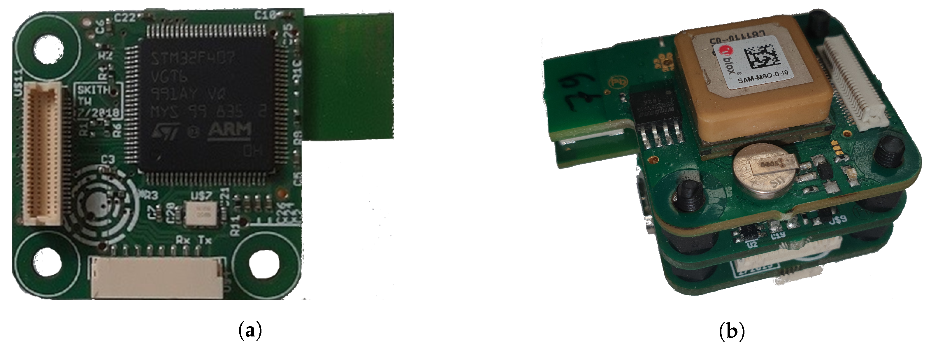
2.2. Node Hardware
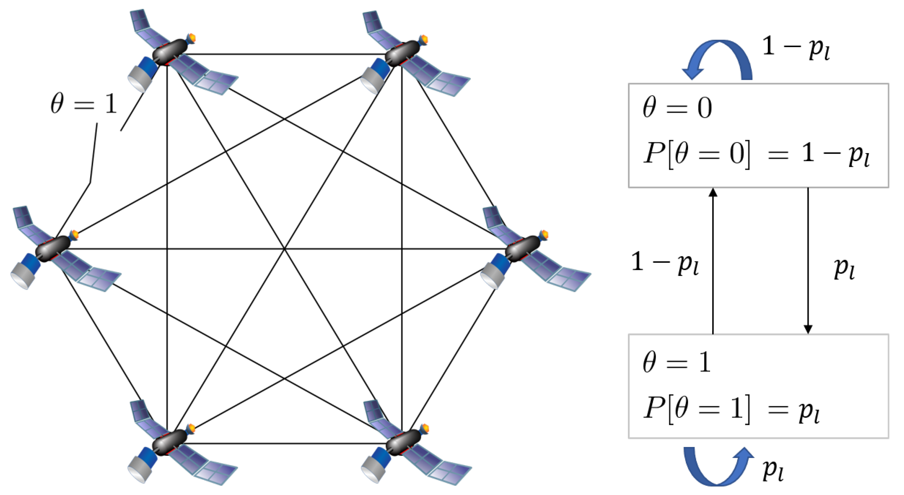
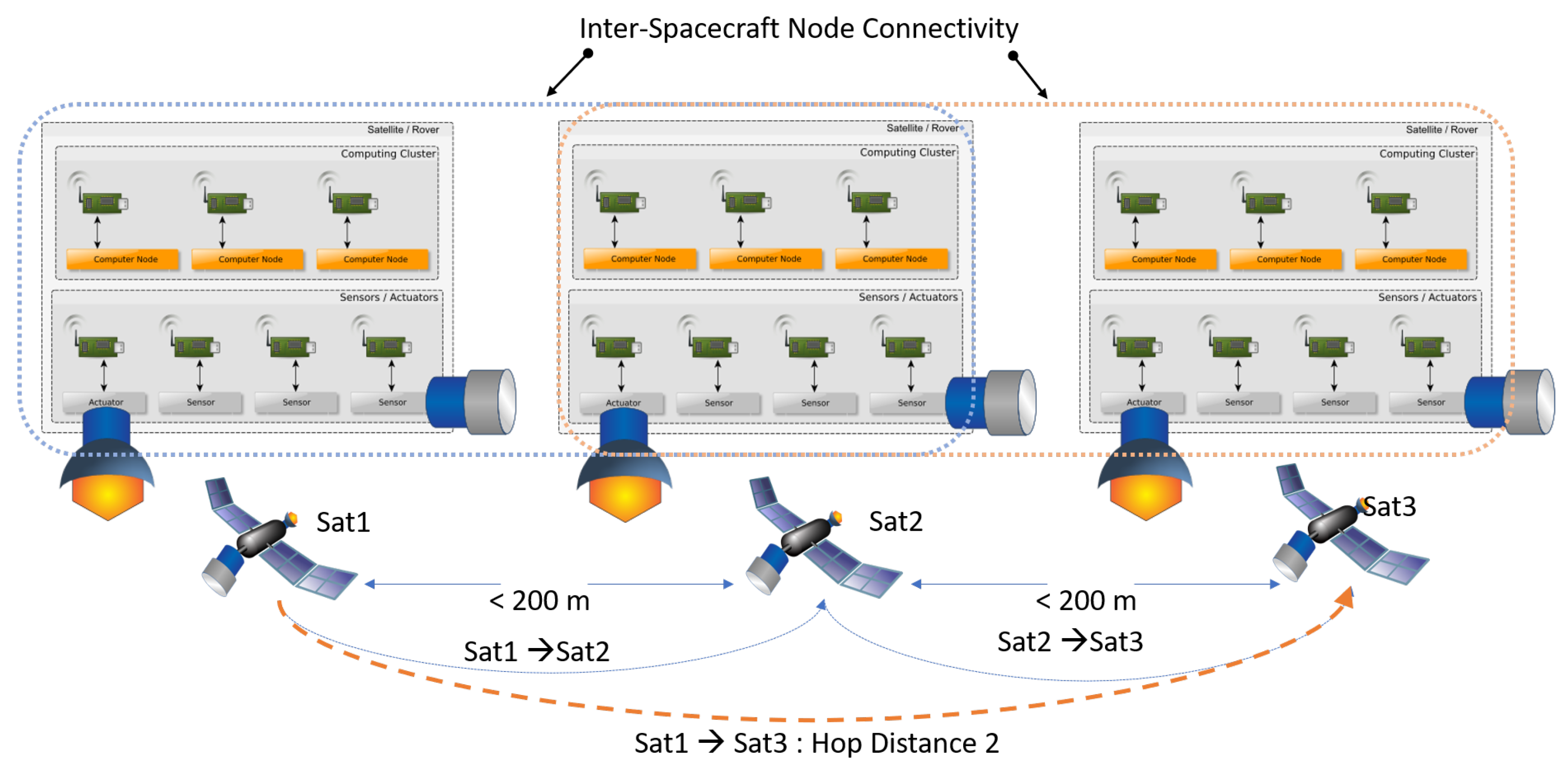
2.3. Node Network
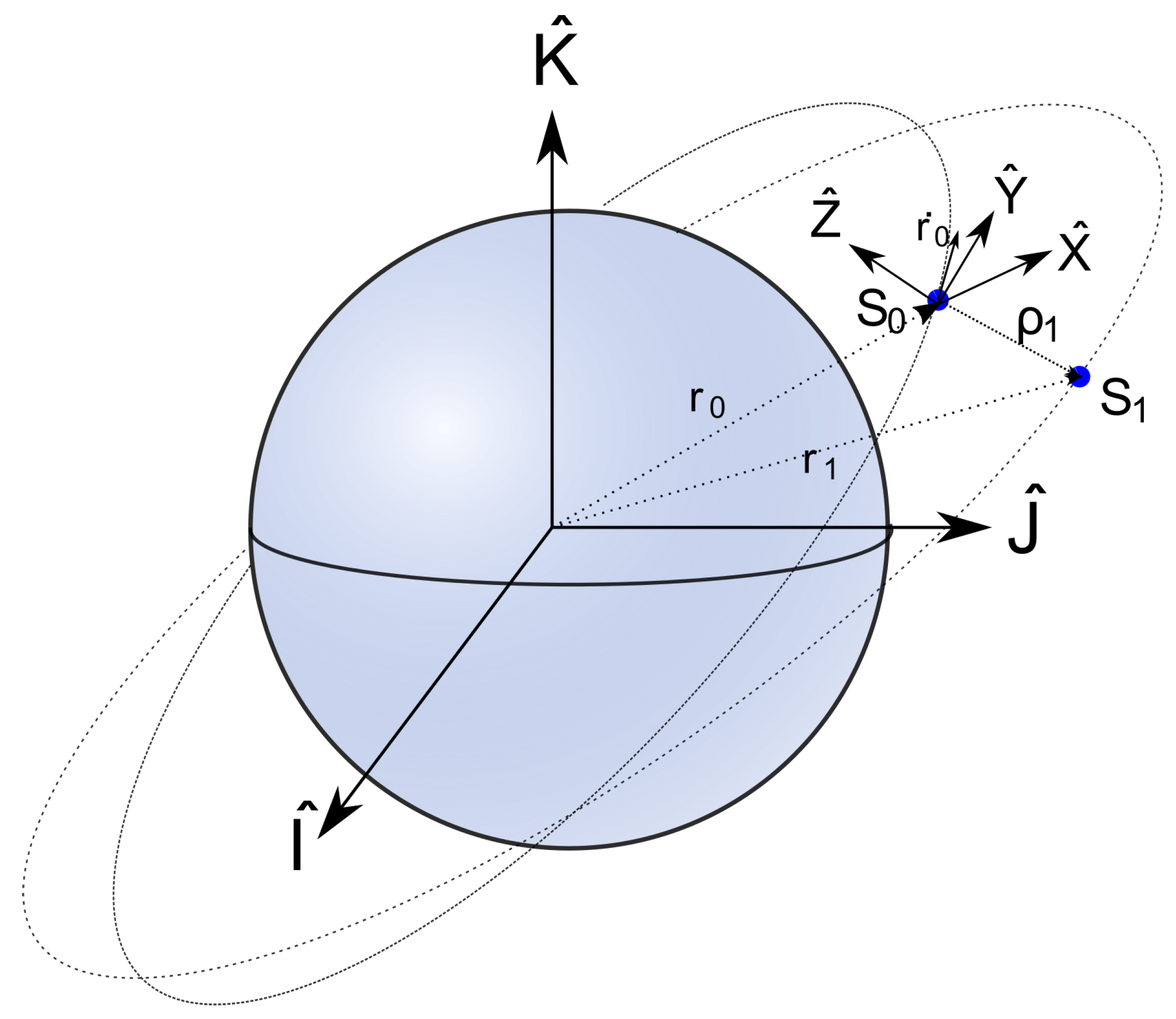
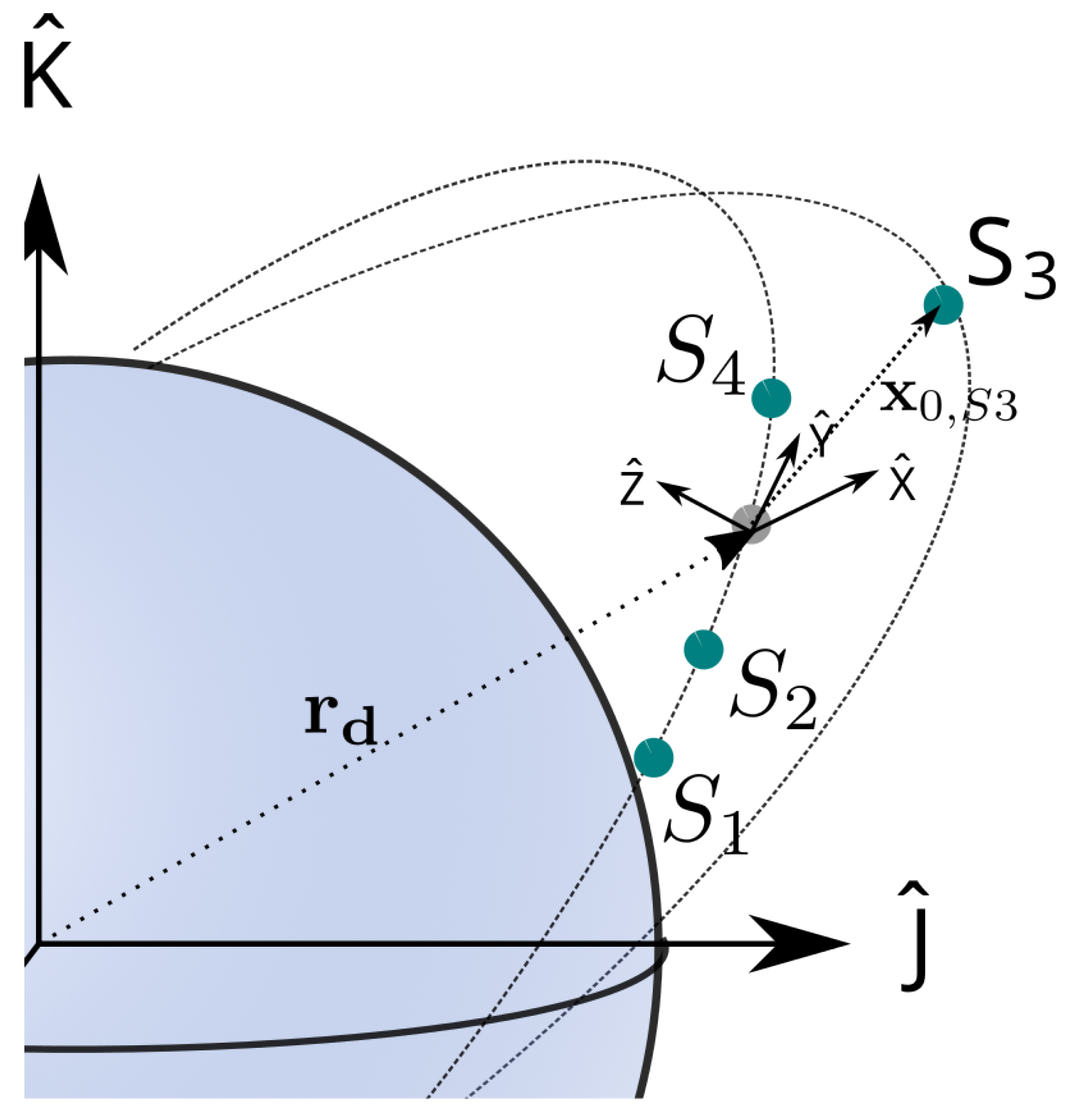
2.4. Satellite Formation-Dynamic Model
2.5. Networked Model Predictive Formation Control
- 1.
- Robust detection of controller loss/failure
- 2.
- Recovery by intelligent re-assigning a new controller node to perform the original controller’s task
2.6. Controller Node Failure-Detection
2.7. Controller Node Failure-Recovery
- DC1:
- It should scale with the number of nodes in the network
- DC2:
- Candidate selection should put a low processing burden on the computing power limited initiator node
- DC3:
- Candidate selection should not take longer than to avoid an empty command buffer at the actuator node.
- DC4:
- Required communication should be kept minimal
- DC5:
- The possibility to include multiple objectives in the candidate selection
- AO1:
- High Quality-of-Service (QoS) of the new controller for the control-loop
- AO2:
- Avoidance of unnecessary burden on the network during control execution
- AO3:
- Avoidance of single-point of failures and unbalanced load on the computing nodes in the network
2.7.1. Auction Based Task Allocation
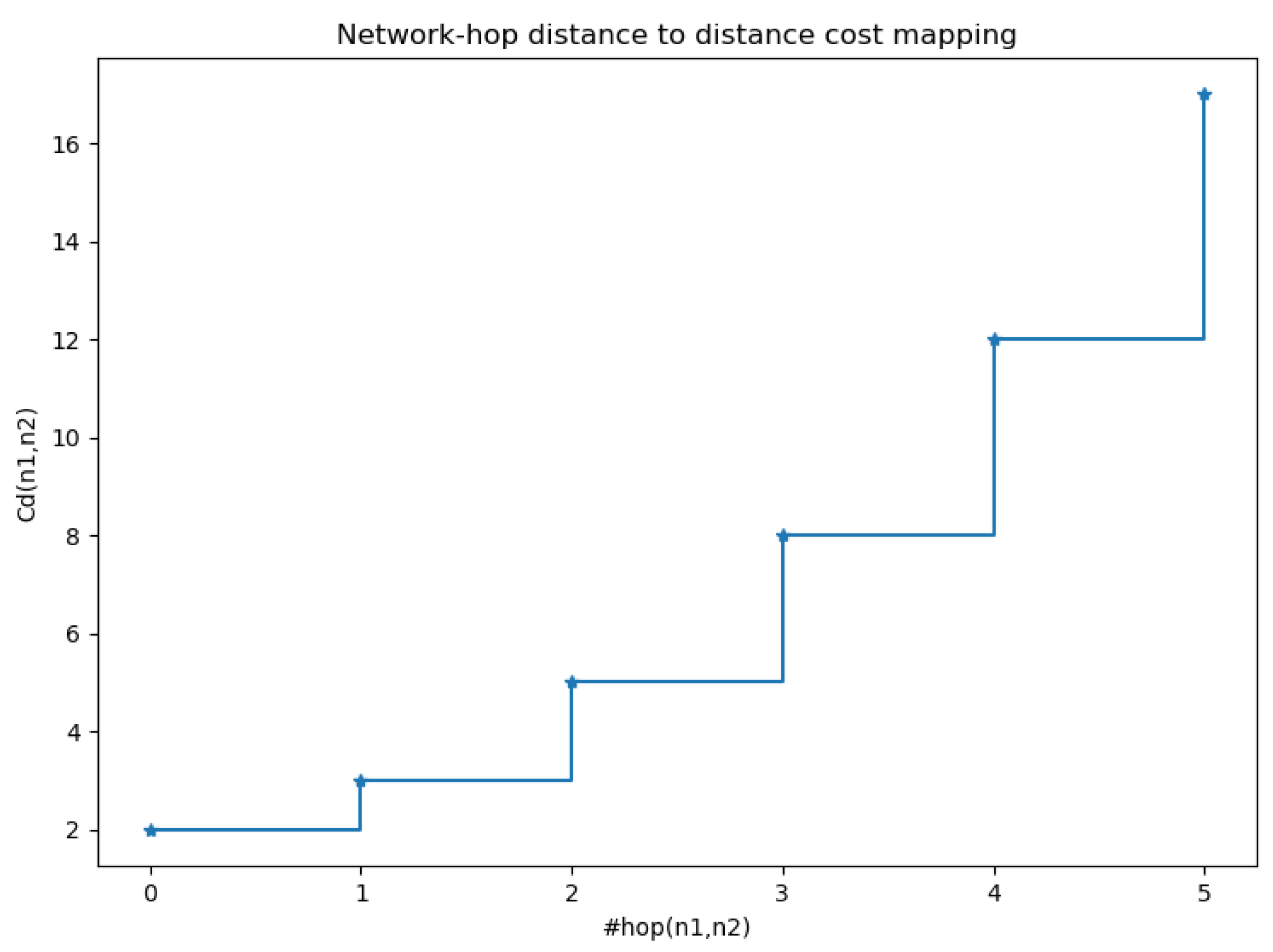
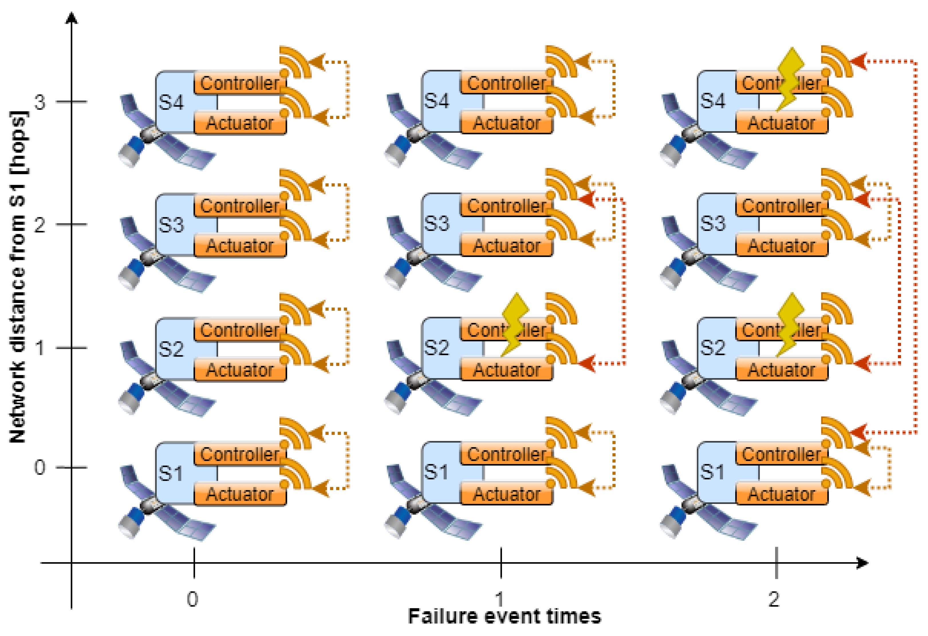
2.7.2. Proximity Criterion
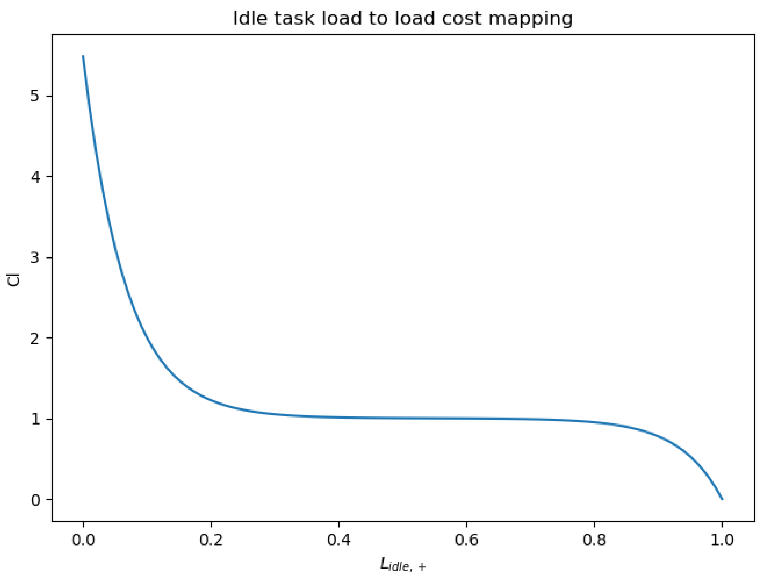
2.7.3. Load Criterion
- 1.
- The way in which the operating system running on the node schedules the individual tasks
- 2.
- The characteristics and run times of other tasks already running on the node
- 3.
- The hardware processing capability of the node
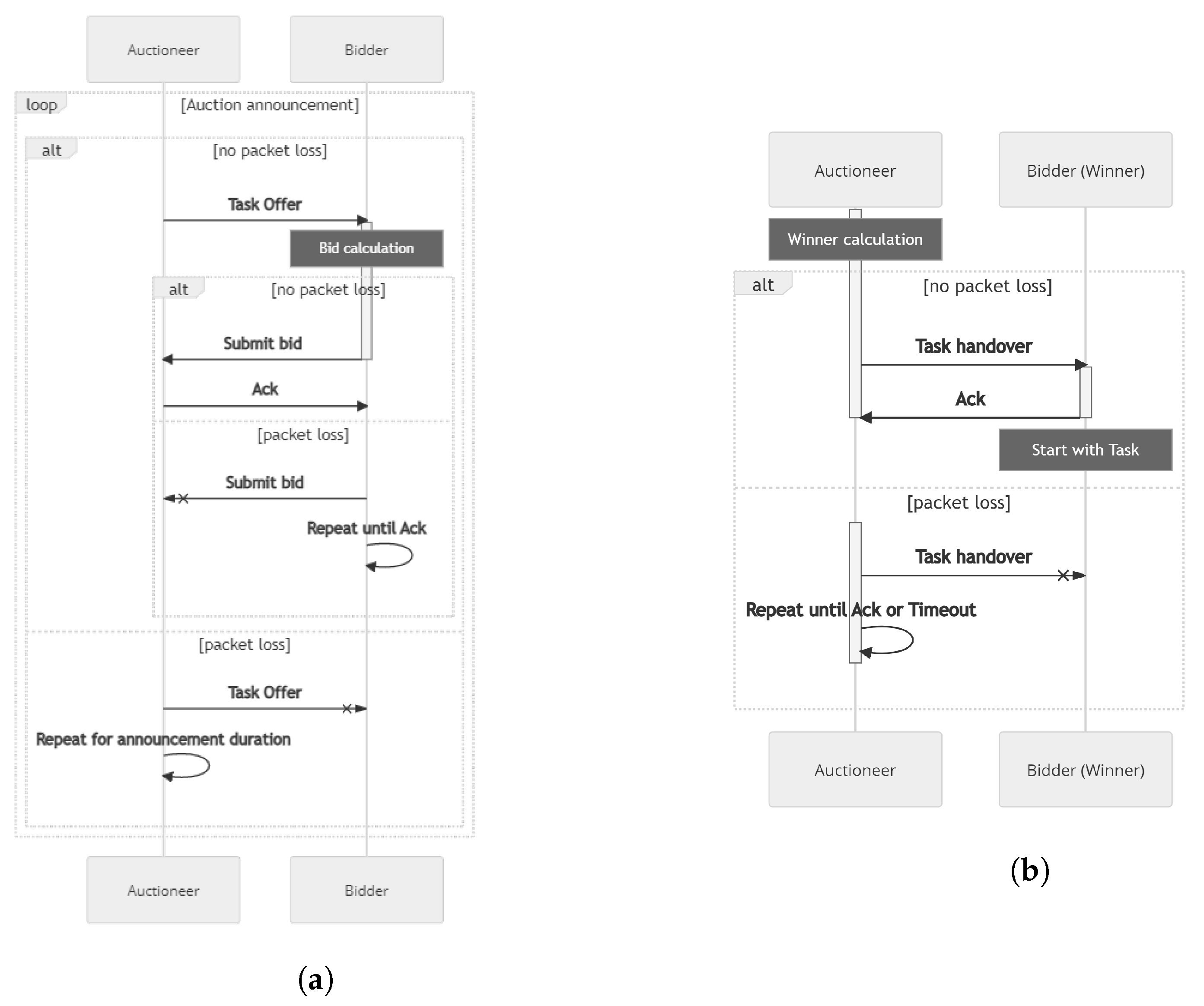
2.7.4. Auction Sequence
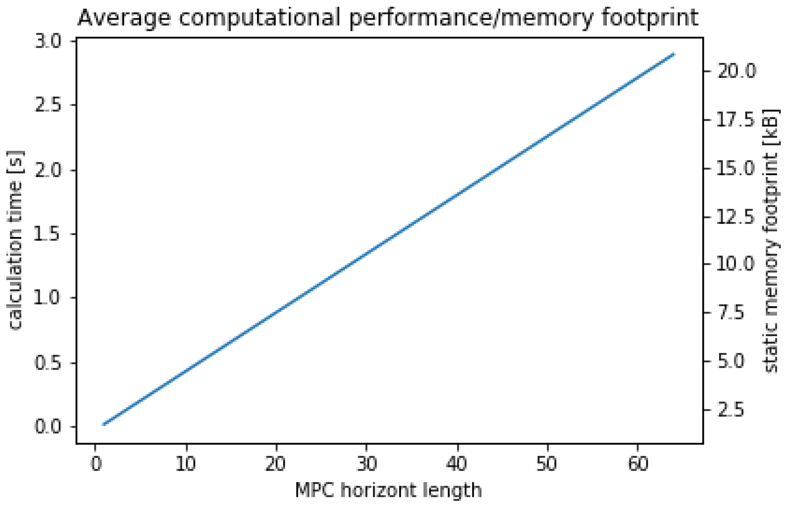
2.7.5. Optimality of Control Task Assignment
3. Results
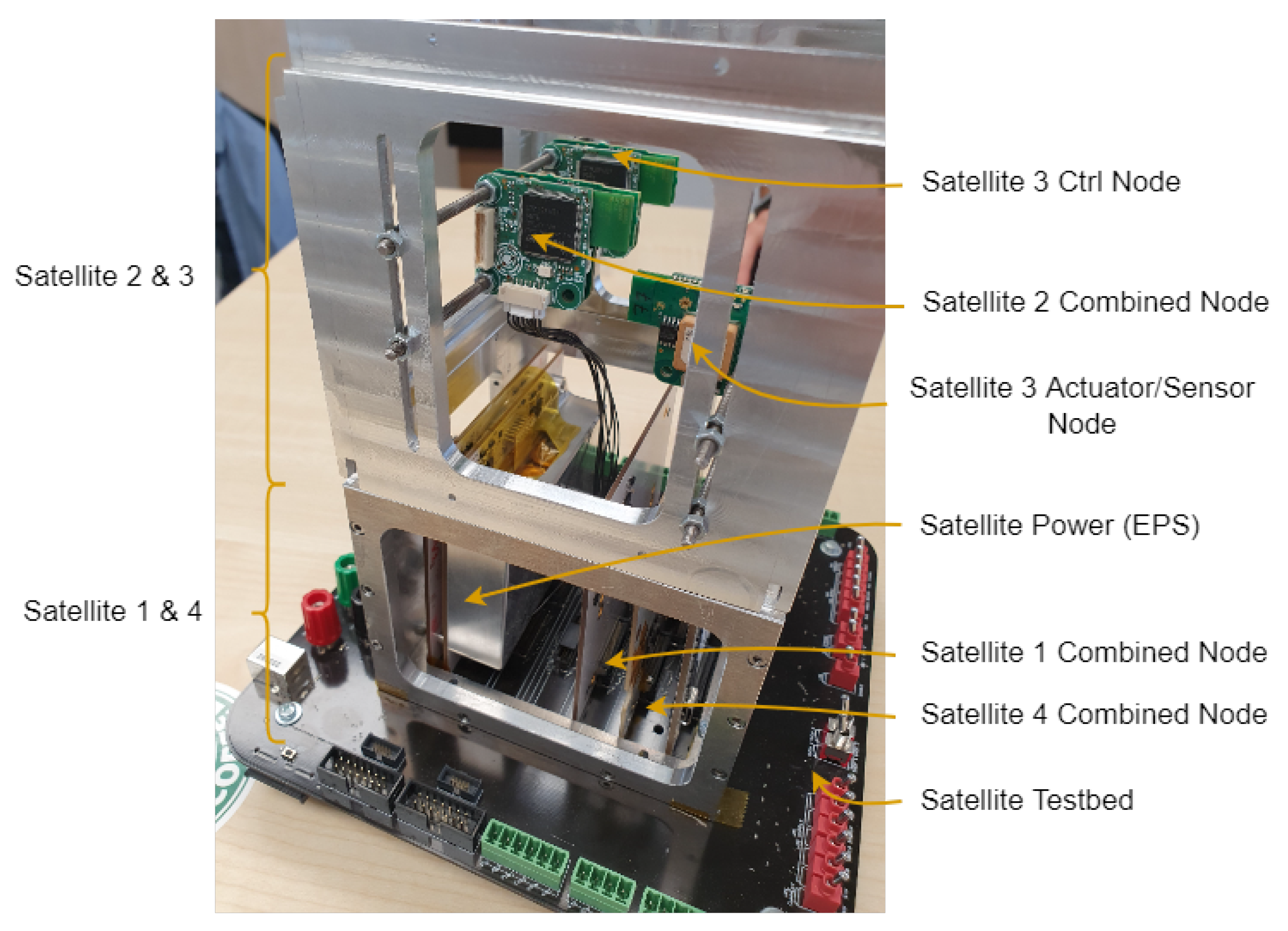
3.1. Hardware Testsetup
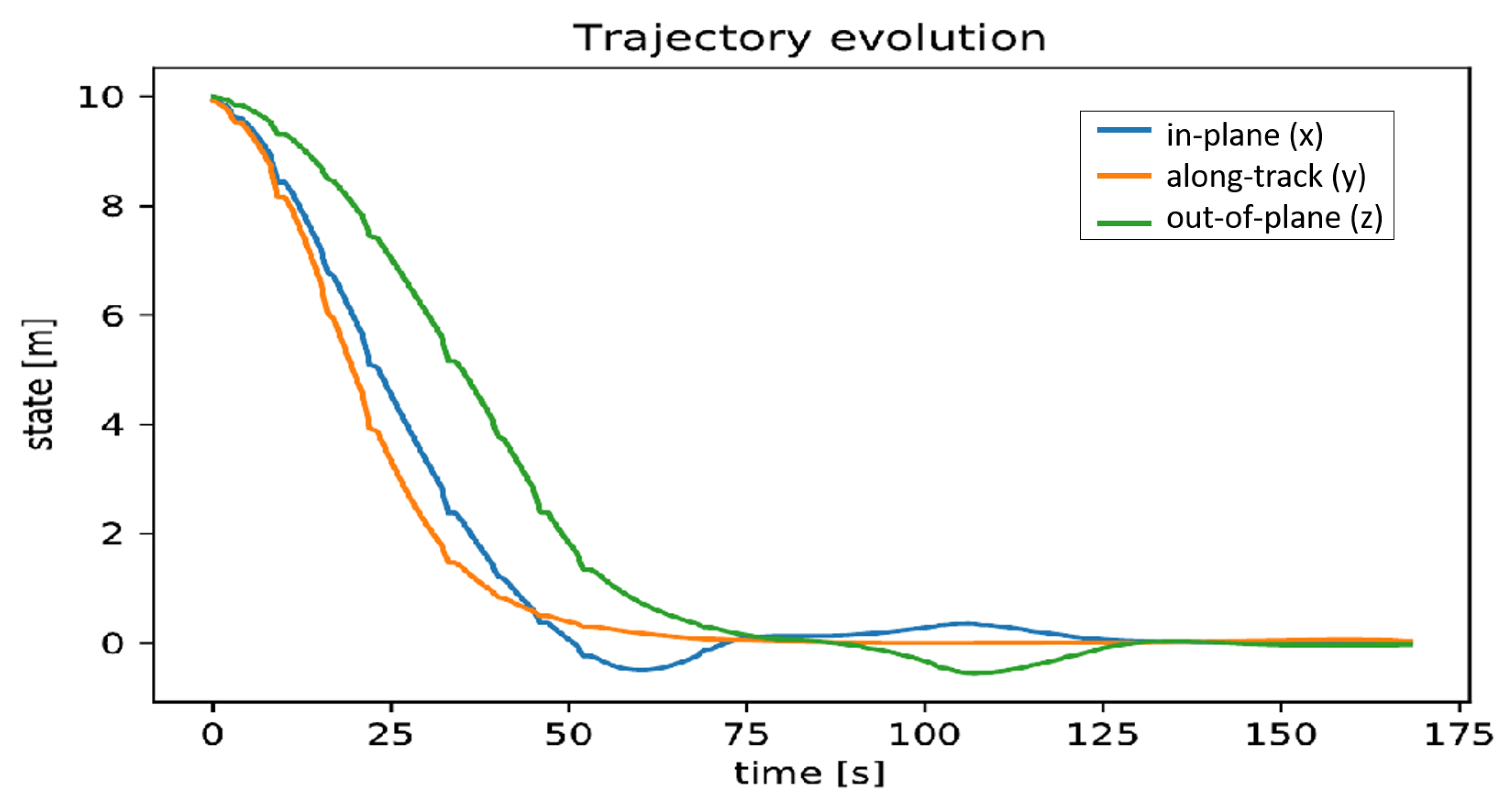
3.2. Control Performance under Nominal Conditions
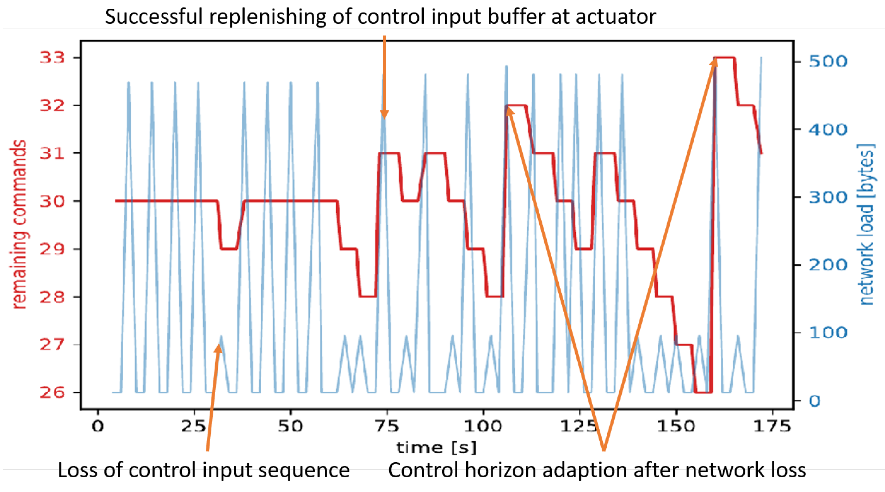
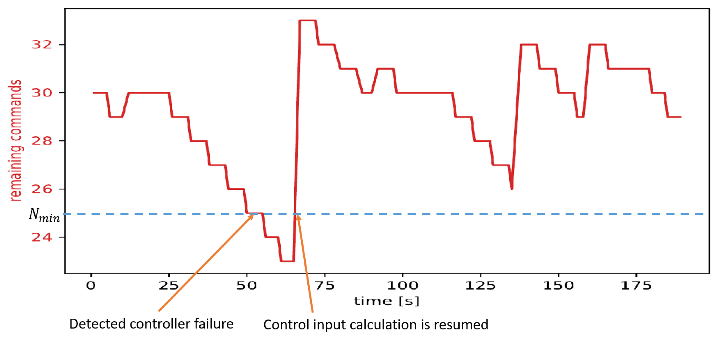
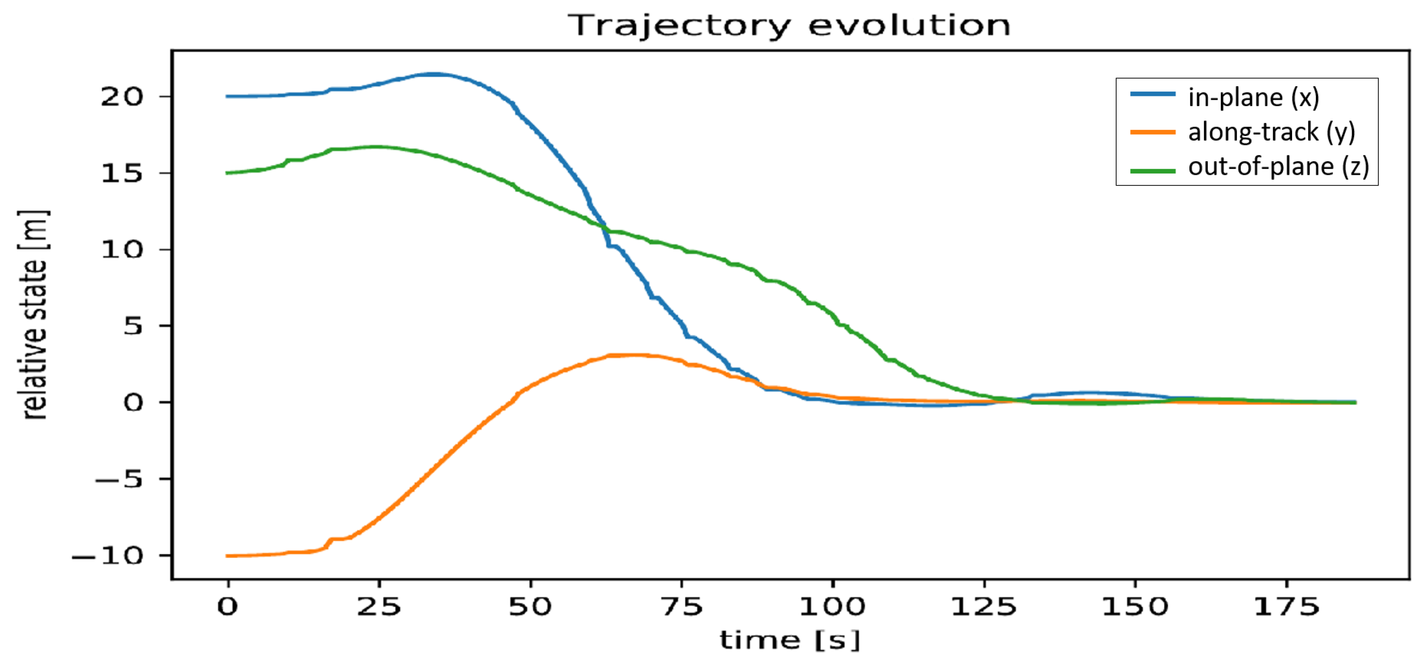
3.3. Controller Failure with Reassignment
4. Discussion
Author Contributions
Funding
Conflicts of Interest
Abbreviations
| AI | Artificial Intelligence |
| CAN | Controller-Area-Network |
| COTS | Commercial off-the-Shelf |
| DARE | Discrete-Time Algebraic Riccati Equation |
| ECI | Earth-Centered Inertial |
| EPS | Electric Power Supply |
| EWMA | Exponentially-Weighted-Moving-Average |
| GAP | General-Assignment-Problem |
| HAL | Hardware-Abstraction-Layer |
| HCW | Hill–Clohessy–Wiltshire |
| LTI | Linear Time-Invariant |
| LVLH | Local-Vertical, Local-Horizontal |
| MAC | Media Access Control |
| MPC | Model Predictive Control |
| OCP | Optimal Control Problem |
| QoS | Quality-of-Service |
| UAV | Unmanned Aerial Vehicle |
References
- Cappelletti, C.; Battistini, S.; Malphrus, B.K. Cubesat Handbook from Mission Design to Operations; Academic Press: London, UK, 2021; Available online: https://www.sciencedirect.com/science/book/9780128178843 (accessed on 1 July 2022).
- Villela, T.; Costa, C.A.; Brandão, A.M.; Bueno, F.T.; Leonardi, R. Towards the Thousandth CubeSat: A Statistical Overview. Int. J. Aerosp. Eng. 2019, 2019, 1–13. Available online: https://www.hindawi.com/journals/ijae/2019/5063145/ (accessed on 1 June 2022). [CrossRef]
- Marinella, M.J. Radiation Effects in Advanced and Emerging Nonvolatile Memories. IEEE Trans. Nucl. Sci. 2021, 68, 546–572. [Google Scholar] [CrossRef]
- Brown, O.; Eremenko, P. Fractionated Space Architectures: A Vision for Responsive Space; Technical Report; Defense Advanced Research Projects Agency: Arlington, VA, USA, 2006. [Google Scholar]
- Mikschl, T.; Montenegro, S.; Hilgarth, A.; Kempf, F.; Schilling, K.; Tzschichholz, T. Resource Sharing, Communication and Control for Fractionated Spacecraft (YETE). In Proceedings of the 10th Symposium on Small Satellites for Earth Observation, Berlin, Germany, 20–24 April 2015. [Google Scholar]
- Guo, J.; Maessen, D.C.; Gill, E.K.A. Fractionated Spacecraft: The New Sprout in Distributed Space Systems. In Proceedings of the 60th International Astronautical Congress: IAC 2009, Daejeon, Korea, 12–16 October 2009. [Google Scholar]
- Kwon, D.; Cheplak, M. Applications of Fractionated Spacecraft Architectures. In Proceedings of the AIAA SPACE 2011 Conference & Exposition, Long Beach, CA, USA, 27–29 September 2011; p. 7131. [Google Scholar]
- Mathieu, C.; Weigel, A. Assessing the Flexibility Provided by Fractionated Spacecraft. In Proceedings of the Space 2005, AIAA, Long Beach, CA, USA, 30 August–1 September 2005; p. 6700. [Google Scholar]
- Mathieu, C.; Weigel, A. Assessing the Fractionated Spacecraft Concept. In Proceedings of the Space 2006, AIAA, San Jose, CA, USA, 19–21 September 2006; p. 7212. [Google Scholar]
- Brown, O.; Eremenko, P.; Bille, M. Fractionated Space Architectures: Tracing the Path to Reality. In Proceedings of the AIAA/USU Conference on Small Satellites, Logan, UT, USA, 10–13 August 2009. [Google Scholar]
- Brown, O.; Eremenko, P.; Collopy, P. Value-Centric Design Methodologies for Fractionated Spacecraft: Progress Summary from Phase I of the DARPA System F6 Program. In Proceedings of the AIAA Space 2009 Conference & Exposition, Pasadena, CA, USA, 14–17 September 2009; p. 6540. [Google Scholar]
- DARPA Cancels Formation-Flying Satellite Demo. Available online: https://spacenews.com/35375darpa-cancels-formation-flying-satellite-demo/ (accessed on 1 June 2022).
- Di, F.; Li, A.; Guo, Y.; Wang, C.; Wang, L. Attitude Tracking Control for Fractionated Spacecraft with Actuator Failures under Adaptive Event-Triggered Strategy. In Advances in Space Research; Elsevier: Amsterdam, The Netherlands, 2022. [Google Scholar]
- Xu, M.; Liang, Y.; Tan, T.; Wei, L. Cluster Flight Control for Fractionated Spacecraft on an Elliptic Orbit. Celest. Mech. Dyn. Astron. 2016, 125, 383–412. [Google Scholar] [CrossRef]
- Chu, J.; Guo, J.; Gill, E. Decentralized Autonomous Planning of Cluster Reconfiguration for Fractionated Spacecraft. Acta Astronaut. 2016, 123, 397–408. [Google Scholar] [CrossRef]
- Wan, S.H.; Song, J.L.; Chen, J.; Hu, M. Hybrid Approach to Optimize the Cluster Flying Orbit for Fractionated Spacecraft Based on PSO-SQP Algorithm. In Applied Mechanics and Materials; Trans Tech Publications Ltd.: Wollerau, Switzerland, 2013; Volume 341, pp. 1144–1149. [Google Scholar]
- Mosleh, M.; Dalili, K.; Heydari, B. Optimal Modularity for Fractionated Spacecraft: The Case of System F6. Procedia Comput. Sci. 2014, 28, 164–170. [Google Scholar] [CrossRef]
- Li, X.; Yao, Y.; Yang, B.; Wang, L. Guidance Strategy Design for Space Debris Removal Using Fractionated Spacecraft. In Proceedings of the 2016 IEEE Chinese Guidance, Navigation and Control Conference (CGNCC), Nanjing, China, 12–14 August 2016; pp. 264–270. [Google Scholar]
- Alandihallaj, M.A.; Emami, M.R. Multiple-Payload Fractionated Spacecraft for Earth Observation. Acta Astronaut. 2022, 191, 451–471. [Google Scholar]
- Schervan, T.A.; Kortmann, M.; Schroder, K.; Kreisel, J. iBOSS Modular Plug & Play-Standardized Building Block Solutions for Future Space Systems Enhancing Capabilities and Flexibility, Design, Architecture and Operations. In Proceedings of the 68th International Astronautical Congress (IAC), Adelaide, Australia, 25–29 September 2017. [Google Scholar]
- Kortman, M.; Ruhl, S.; Weise, J.; Kreisel, J.; Schervan, T.; Schmidt, H.; Dafnis, A. Building Block Based iBoss Approach: Fully Modular Systems with Standard Interface to Enhance Future Satellites. In Proceedings of the 66th International Astronautical Congress (Jerusalem), Jerusalem, Israel, 12–16 October 2015; pp. 1–11. [Google Scholar]
- InnoCube-Chair of Computer Science VIII-Aerospace Information Technology. 2022. Available online: https://www.informatik.uni-wuerzburg.de/en/aerospaceinfo/wissenschaft-forschung/innocube/ (accessed on 15 July 2022).
- Grzesik, B.; Baumann, T.; Walter, T.; Flederer, F.; Sittner, F.; Dilger, E.; Gläsner, S.; Kirchler, J.L.; Tedsen, M.; Montenegro, S. InnoCube—A Wireless Satellite Platform to Demonstrate Innovative Technologies. Aerospace 2021, 8, 127. [Google Scholar] [CrossRef]
- Mikschl, T.; Hilgarth, A.; Kempf, F.; Kheirkah, A.; Tzschichholz, T.; Montenegro, S.; Schilling, K. YETE: Distributed, Networked Embedded Control Approaches for Efficient, Reliable Mobile Systems. DASIA 2014-Data Syst. Aerosp. 2014, 725, 20. [Google Scholar]
- Kempf, F.; Santa Cruz, U.; Scharnagl, J.; Schilling, K. Networked and Distributed Cooperative Attitude Control of Fractionated Small Satellites. In Proceedings of the 69th International Astronautical Congress, Bremen, Germany, 1–5 October 2018. [Google Scholar]
- Kempf, F.; Hilgarth, A.; Kheirkhah, A.; Mikschl, T.; Tzschichholz, T.; Montenegro, S.; Schilling, K. Reliable Networked Distributed On-Board Data Handling Using a Modular Approach with Heterogeneous Components. In Proceedings of the 4S Symposium, Majorca, Spain, 26–30 May 2014. [Google Scholar]
- Catanoso, D.; Kempf, F.; Schilling, K.; D’Amico, S. Networked Model Predictive Control for Satellite Formation Flying. In Proceedings of the 10th International Workshop of Satellites Constellations and Formation, Glasgow, UK, 16–19 July 2019; p. 16. [Google Scholar]
- Heemels, W.; Johansson, K.; Tabuada, P. An Introduction to Event-Triggered and Self-Triggered Control. In Proceedings of the 2012 IEEE 51st IEEE Conference on Decision and Control (CDC), Maui, HI, USA, 10–13 December 2012; pp. 3270–3285. [Google Scholar] [CrossRef]
- Peng, C.; Song, Y.; Peng Xie, X.; Zhao, M.; Fei, M.R. Event-Triggered Output Tracking Control for Wireless Networked Control Systems with Communication Delays and Data Dropouts. IET Control. Theory Appl. 2016, 10, 2195–2203. [Google Scholar] [CrossRef]
- Zhang, L.; Swain, A.; Zhang, D.; Wen, S. A Discrete Event-Triggered Scheme for Networked Control Systems. In Proceedings of the 2021 IEEE 30th International Symposium on Industrial Electronics (ISIE), Kyoto, Japan, 20–23 June 2021; pp. 1–6. [Google Scholar]
- Wang, C.; Guo, L.; Wen, C.; Hu, Q.; Qiao, J. Event-Triggered Adaptive Attitude Tracking Control for Spacecraft With Unknown Actuator Faults. IEEE Trans. Ind. Electron. 2020, 67, 2241–2250. [Google Scholar] [CrossRef]
- Wang, C.; Li, Y.; Hu, Q.; Huang, J. Event-Triggered Adaptive Control for Attitude Tracking of Spacecraft. Chin. J. Aeronaut. 2019, 32, 454–462. [Google Scholar] [CrossRef]
- Wu, B.; Shen, Q.; Cao, X. Event-Triggered Attitude Control of Spacecraft. Adv. Space Res. 2018, 61, 927–934. [Google Scholar] [CrossRef]
- Kheirkhah, A.; Kempf, F.; Tzschichholz, T.; Schilling, K. Robust Distributed Control for a Mechanical-Electrical Demonstrator Considering Communication Constraints. IFAC-PapersOnLine 2015, 48, 246–251. [Google Scholar] [CrossRef]
- Montenegro, S.; Dannemann, F. RODOS-real Time Kernel Design for Dependability. DASIA 2009-DAta Syst. Aerosp. 2009, 669, 66. [Google Scholar]
- Walter, T.; Hilgarth, A.; Mikschl, T.; Montenegro, S. VIDANA: A Fault Tolerant Approach for a Distributed Data Management System in Nano-Satellites. In Proceedings of the 10th Symposium on Small Satellites for Earth Observation, Berlin, Germany, 6–10 May 2019. [Google Scholar]
- Mikschl, T.; Rauscher, R.; Montenegro, S.; Schilling, K.; Kempf, F.; Tzschichholz, T. Collision Free Protocol for Ultrawideband Links in Distributed Satellite Avionics; University of Würzburg: Würzburg, Germany, 2016. [Google Scholar]
- Fortescue, P.; Swinerd, G.; Stark, J. Spacecraft Systems Engineering; John Wiley & Sons: Hoboken, NJ, USA, 2011. [Google Scholar]
- Clohessy, R.S.; Wiltshire. The Clohessy-Wiltshire Equations of Relative Motion. J. Aerosp. Sci. 1960, 27, 653–658. [Google Scholar] [CrossRef]
- Hrovat, D.; Di Cairano, S.; Tseng, H.; Kolmanovsky, I. The Development of Model Predictive Control in Automotive Industry: A Survey. In Proceedings of the 2012 IEEE International Conference on Control Applications, Dubrovnik, Croatia, 3–5 October 2012; pp. 295–302. [Google Scholar] [CrossRef]
- Qian, X.; Navarro, I.; de La Fortelle, A.; Moutarde, F. Motion Planning for Urban Autonomous Driving Using Bézier Curves and MPC. In Proceedings of the 2016 IEEE 19th International Conference on Intelligent Transportation Systems (ITSC), Rio de Janeiro, Brazil, 1–4 November 2016; pp. 826–833. [Google Scholar] [CrossRef]
- Yu, S.; Hirche, M.; Huang, Y.; Chen, H.; Allgöwer, F. Model Predictive Control for Autonomous Ground Vehicles: A Review. Auton. Intell. Syst. 2021, 1, 4. Available online: https://link.springer.com/10.1007/s43684-021-00005-z (accessed on 15 June 2022). [CrossRef]
- Valmorbida, A. Development and testing of model predictive control strategies for spacecraft formation flying. Ph.D. Thesis, Universita degli Studi di Padova, Padova, Italy, 2014. Available online: https://www.research.unipd.it/handle/11577/3423708?1/valmorbida_andrea_tesi.pdf (accessed on 8 June 2022).
- Englert, T. A Software Framework for Embedded Nonlinear Model Predictive Control Using a Gradient-Based Augmented Lagrangian Approach (GRAMPC). Optim. Eng. 2019, 20, 769–809. [Google Scholar] [CrossRef]
- Christofides, P.D.; Liu, J.; Muñoz de la Peña, D. Networked and Distributed Predictive Control. In Advances in Industrial Control; Springer: London, UK, 2011; Available online: http://link.springer.com/10.1007/978-0-85729-582-8 (accessed on 10 June 2022).
- Kalman, R.; Bertram, J. Control System Analysis and Design via the Second Method of Lyapunov: (I) Continuous-Time Systems (II) Discrete Time Systems. IRE Trans. Autom. Control 1959, 4, 112. [Google Scholar] [CrossRef]
- Burk, D.; Volz, A.; Graichen, K. Towards a Modular Framework for Distributed Model Predictive Control of Nonlinear Neighbor-Affine Systems. In Proceedings of the 2019 IEEE 58th Conference on Decision and Control (CDC), Nice, France, 11–13 December 2019; pp. 5279–5284. Available online: https://ieeexplore.ieee.org/document/9029800/ (accessed on 1 May 2022).
- Kapernick, B.; Graichen, K. The Gradient Based Nonlinear Model Predictive Control Software GRAMPC. In Proceedings of the 2014 European Control Conference, ECC 2014, Strasbourg, France, 24–27 June 2014. [Google Scholar] [CrossRef]
- Sahni, S.; Gonzalez, T. P-Complete Approximation Problems. J. ACM (JACM) 1976, 23, 555–565. [Google Scholar] [CrossRef]
- Bertsekas, D.P. The Auction Algorithm: A Distributed Relaxation Method for the Assignment Problem. Ann. Oper. Res. 1988, 14, 105–123. Available online: http://link.springer.com/10.1007/BF02186476 (accessed on 15 July 2022). [CrossRef]
- Koenig, S.; Tovey, C.; Lagoudakis, M.; Markakis, V.; Kempe, D.; Keskinocak, P.; Kleywegt, A.; Meyerson, A.; Jain, S. The Power of Sequential Single-Item Auctions for Agent Coordination. In Proceedings of the AAAI, Boston, MA, USA, 16–17 July 2006; Volume 2006, pp. 1625–1629. [Google Scholar]
- Lagoudakis, M.; Berhault, M.; Koenig, S.; Keskinocak, P.; Kleywegt, A. Simple Auctions with Performance Guarantees for Multi-Robot Task Allocation. In Proceedings of the 2004 IEEE/RSJ International Conference on Intelligent Robots and Systems (IROS) (IEEE Cat. No.04CH37566), Sendai, Japan, 28 September–2 October 2004; Volume 1, pp. 698–705. Available online: http://ieeexplore.ieee.org/document/1389434/ (accessed on 10 June 2022).
- Nanjanath, M.; Gini, M. Dynamic Task Allocation for Robots via Auctions. In Proceedings of the 2006 IEEE International Conference on Robotics and Automation, Orlando, FL, USA, 15–19 May 2006; pp. 2781–2786. [Google Scholar] [CrossRef]
- Schneider, E.; Sklar, E.I.; Parsons, S.; Özgelen, A. Auction-Based Task Allocation for Multi-Robot Teams in Dynamic Environments. In Proceedings of the Conference Towards Autonomous Robotic Systems, Liverpool, UK, 8–10 September 2015; pp. 246–257. [Google Scholar]
- Koenig, S.; Tovey, C.A.; Zheng, X.; Sungur, I. Sequential Bundle-Bid Single-Sale Auction Algorithms for Decentralized Control. In Proceedings of the IJCAI, Hyderabad, India, 6–12 January 2007; pp. 1359–1365. [Google Scholar]
- Gerkey, B.P.; Matarić, M.J. A Formal Analysis and Taxonomy of Task Allocation in Multi-Robot Systems. Int. J. Robot. Res. 2004, 23, 939–954. [Google Scholar] [CrossRef] [Green Version]


| Node of Sat | Free Load | Hop Distance to S3 | Load Cost Cl | Distance Cost Cd | Bid |
|---|---|---|---|---|---|
| 1 | 25% | 2 | 5.4 | 5 | No Bid |
| 2 | 50% | 1 | 2.35 | 3 | 7 |
| 4 | 45% | 1 | 3.86 | 3 | 11 |
Publisher’s Note: MDPI stays neutral with regard to jurisdictional claims in published maps and institutional affiliations. |
© 2022 by the authors. Licensee MDPI, Basel, Switzerland. This article is an open access article distributed under the terms and conditions of the Creative Commons Attribution (CC BY) license (https://creativecommons.org/licenses/by/4.0/).
Share and Cite
Kempf, F.; Scharnagl, J.; Heil, S.; Schilling, K. Self-Organizing Control-Loop Recovery for Predictive Networked Formation Control of Fractionated Spacecraft. Aerospace 2022, 9, 529. https://doi.org/10.3390/aerospace9100529
Kempf F, Scharnagl J, Heil S, Schilling K. Self-Organizing Control-Loop Recovery for Predictive Networked Formation Control of Fractionated Spacecraft. Aerospace. 2022; 9(10):529. https://doi.org/10.3390/aerospace9100529
Chicago/Turabian StyleKempf, Florian, Julian Scharnagl, Stefan Heil, and Klaus Schilling. 2022. "Self-Organizing Control-Loop Recovery for Predictive Networked Formation Control of Fractionated Spacecraft" Aerospace 9, no. 10: 529. https://doi.org/10.3390/aerospace9100529