
Coupling Effect of Nonlinear Stiffness of Tape Spring Hinges and Flexible Deformation of Panels during Orbit Maneuvers

Abstract
:1. Introduction
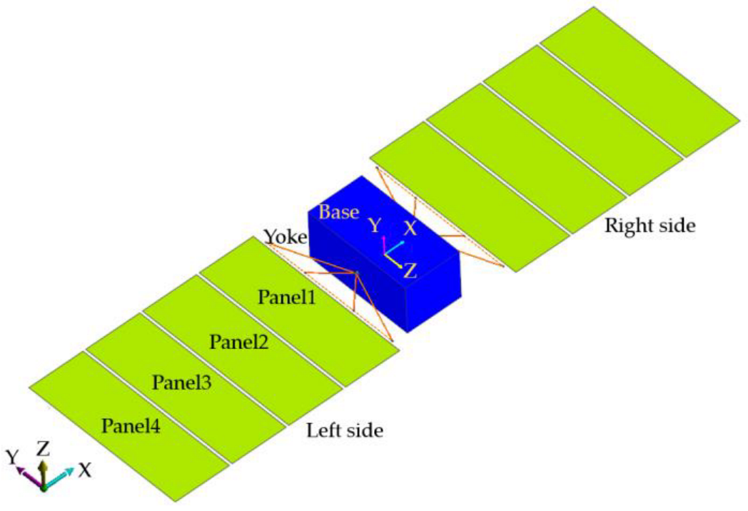
2. Satellite System Model
2.1. Tape Spring Hinge
2.2. Solar Panels
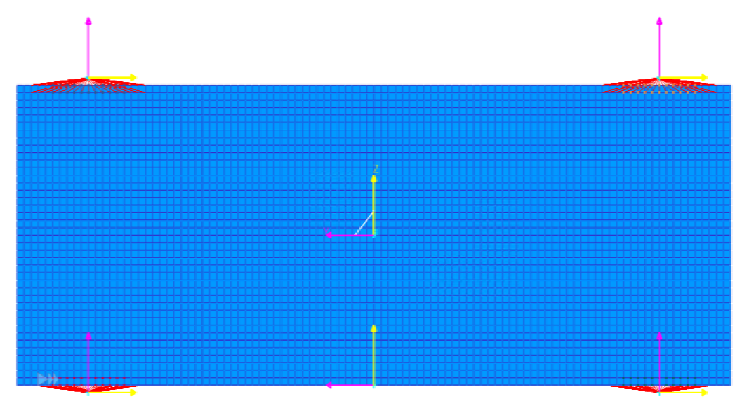
2.2.1. Finite Element Method
2.2.2. Modal Order Reduction Method
3. Simulation Results
3.1. Deployment
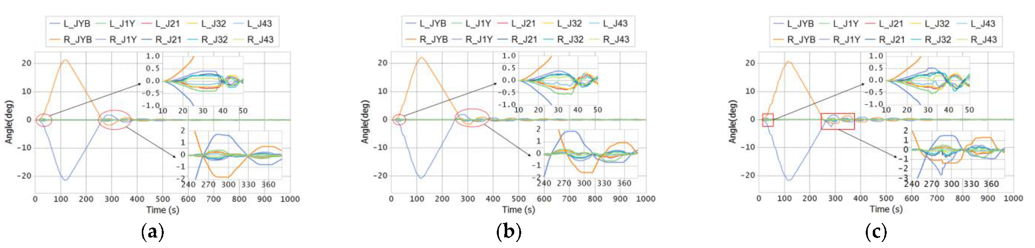
3.2. Orbit Steering
4. Conclusions
- (1)
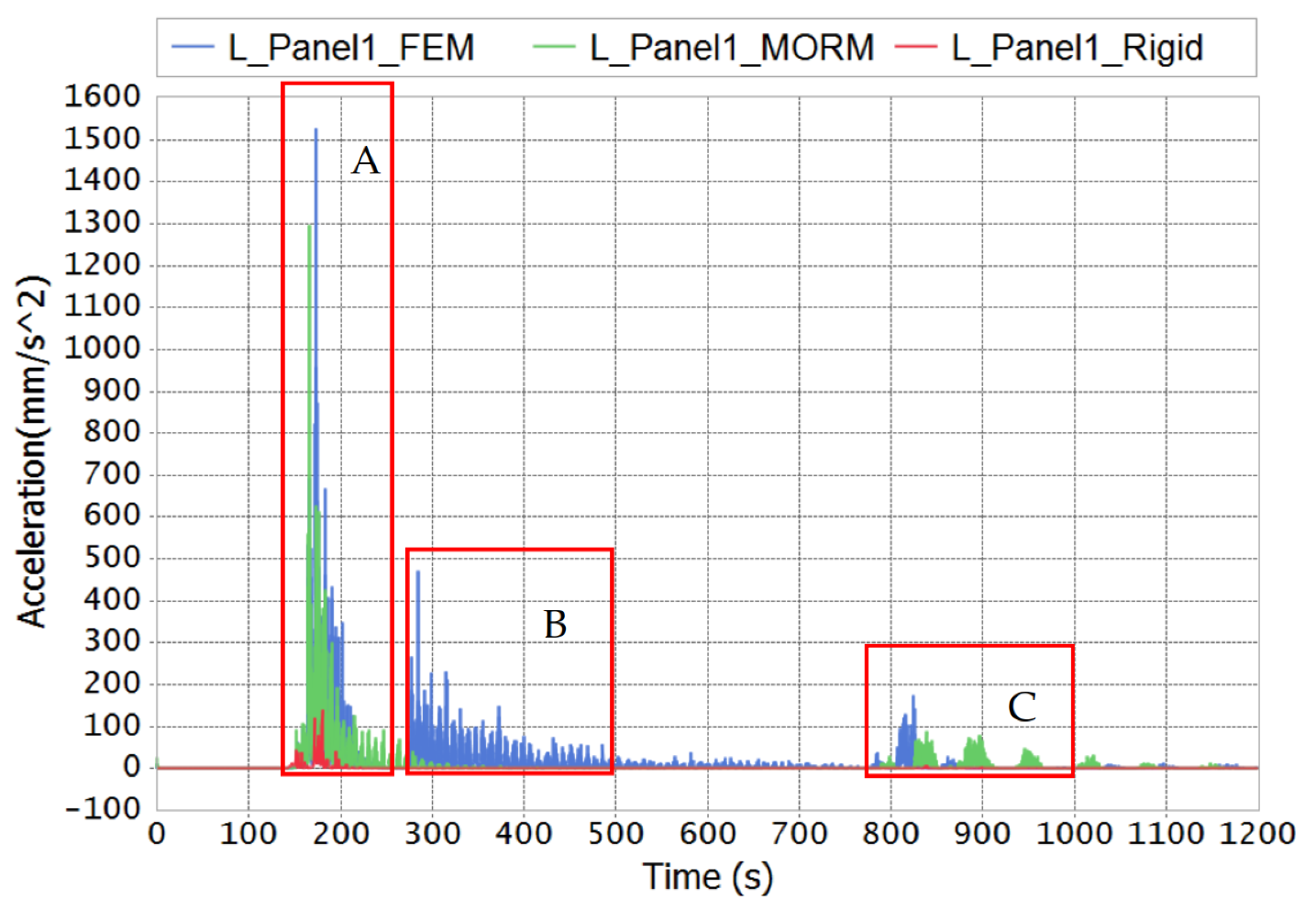
- The linear deformation of panels relieves the inertia forces of panels and weakens the overshoot phenomenon in deployment. Meanwhile, the coupling effect enlarges the overshoot phenomenon.
- (2)
- The left panels are deployed in coincide with the right panels by the rigid model and MORM model. The coupling effect affects the sequence of deployment, and the panels are deployed asymmetrically by the FEM model.
- (3)
- The lock-up torque adheres the panel edges and generates local deformation in FEM model. The stiffness of TSH is kept in a large range by this local deformation. Panels are locked firmly if the local deformation and TSH can overcome the kinetic energy of the panels. Meanwhile, much vibration is generated if the local deformation and TSH cannot overcome the kinetic energy of the panels’ rotation. Therefore, the stiffness of the TSH should be selected in considering of the local deformation of the panels and the kinetic energy of the panels. In other words, the speed of deployment and steering, the inertia properties of the spacecraft, the structure and material properties of the panels should be considered in design the stiffness of the TSHs.
- (4)
- MORM is much more efficient than FEM in computation.
Author Contributions
Funding
Institutional Review Board Statement
Informed Consent Statement
Data Availability Statement
Acknowledgments
Conflicts of Interest
References
- Wallrapp, O.; Wiedemann, S. Comparison of results in flexible multibody dynamics using various approaches. Nonlinear Dyn. 2003, 34, 189–206. [Google Scholar] [CrossRef]
- Kim, K.-W.; Park, Y. Systematic design of tape spring hinges for solar array by optimization method considering deployment performances. Aerosp. Sci. Technol. 2015, 46, 124–136. [Google Scholar] [CrossRef]
- Wang, W.; Luo, H.; Fu, J.; Wang, H.; Yu, C.; Liu, G.; Wei, Q.; Wu, S. Comparative application analysis and test verification on equivalent modeling theories of honeycomb sandwich panels for satellite solar arrays. Adv. Compos. Lett. 2020, 29, 0963693520963127. [Google Scholar] [CrossRef]
- Wallrapp, O.; Wiedemann, S. Simulation of Deployment of a Flexible Solar Array. Multibody Syst. Dyn. 2002, 7, 101–125. [Google Scholar] [CrossRef]
- Luo, H.; Wang, W.; Fu, J.; Jiao, L. Finite element model updating of satellite sailboard based on sensitivity analysis. Shock. Vib. 2019, 2019, 4547632. [Google Scholar] [CrossRef]
- Fehr, J.; Eberhard, P. Simulation process of flexible multibody systems with non-modal model order reduction techniques. Multibody Syst. Dyn. 2011, 25, 313–334. [Google Scholar] [CrossRef]
- Liu, L.; Cao, D.; Wei, J.; Tan, X.; Yu, T. Rigid-flexible coupling dynamic modeling and vibration control for a three-axis stabilized spacecraft. J. Vib. Acoust. 2017, 139, 041006. [Google Scholar] [CrossRef]
- Mallikarachchi, H.; Pellegrino, S. Quasi-static folding and deployment of ultrathin composite tape-spring hinges. J. Spacecr. Rocket. 2011, 48, 187–198. [Google Scholar] [CrossRef]
- Oberst, S.; Tuttle, S. Nonlinear dynamics of thin-walled elastic structures for applications in space. Mech. Syst. Signal Process. 2018, 110, 469–484. [Google Scholar] [CrossRef]
- Oberst, S.; Tuttle, S.; Griffin, D.; Lambert, A.; Boyce, R. Experimental validation of tape springs to be used as thin-walled space structures. J. Sound Vib. 2018, 419, 558–570. [Google Scholar] [CrossRef]
- Jeong, J.W.; Yoo, Y.I.; Shin, D.K.; Lim, J.H.; Kim, K.W.; Lee, J.J. A novel tape spring hinge mechanism for quasi-static deployment of a satellite deployable using shape memory alloy. Rev. Sci. Instrum. 2014, 85, 025001. [Google Scholar] [CrossRef]
- Lee, C.-H.; Jeong, J.-W.; Kim, Y.-J.; Lee, J.-J. Deployment shock attenuation of a solar array tape hinge by means of the Martensite detwinning of NiTi Shape Memory Alloy. Rev. Sci. Instrum. 2016, 87, 035104. [Google Scholar] [CrossRef] [PubMed]
- Hoffait, S.; Brüls, O.; Granville, D.; Cugnon, F.; Kerschen, G. Dynamic analysis of the self-locking phenomenon in tape-spring hinges. Acta Astronaut. 2010, 66, 1125–1132. [Google Scholar] [CrossRef]
- Dewalque, F.; Rochus, P.; Brüls, O. Importance of structural damping in the dynamic analysis of compliant deployable structures. Acta Astronaut. 2015, 111, 323–333. [Google Scholar] [CrossRef]
- Dewalque, F.; Collette, J.-P.; Brüls, O. Mechanical behaviour of tape springs used in the deployment of reflectors around a solar panel. Acta Astronaut. 2016, 123, 271–282. [Google Scholar] [CrossRef]
- Dewalque, F.; Schwartz, C.; Denoël, V.; Croisier, J.-L.; Forthomme, B.; Brüls, O. Experimental and numerical investigation of the nonlinear dynamics of compliant mechanisms for deployable structures. Mech. Syst. Signal Process. 2018, 101, 1–25. [Google Scholar] [CrossRef]
- Ye, H.; Zhang, Y.; Yang, Q.; Xiao, Y.; Grandhi, R.V.; Fischer, C.C. Optimal design of a three tape-spring hinge deployable space structure using an experimentally validated physics-based model. Struct. Multidiscip. Optim. 2017, 56, 973–989. [Google Scholar] [CrossRef]
- Ye, H.; Zhang, Y.; Yang, Q.; Zhang, B. Quasi-static analysis and multi-objective optimization for tape spring hinge. Struct. Multidiscip. Optim. 2019, 60, 2417–2430. [Google Scholar] [CrossRef]
- Guinot, F.; Bourgeois, S.; Cochelin, B.; Blanchard, L. A planar rod model with flexible thin-walled cross-sections. Application to the folding of tape springs. Int. J. Solids Struct. 2012, 49, 73–86. [Google Scholar] [CrossRef]
- Soykasap, O. Analysis of tape spring hinges. Int. J. Mech. Sci. 2007, 49, 853–860. [Google Scholar] [CrossRef]
- Yang, H.; Liu, R.; Wang, Y.; Deng, Z.; Guo, H. Experiment and multiobjective optimization design of tape-spring hinges. Struct. Multidiscip. Optim. 2015, 51, 1373–1384. [Google Scholar] [CrossRef]
- Kim, K.-W.; Park, Y. Solar array deployment analysis considering path-dependent behavior of a tape spring hinge. J. Mech. Sci. Technol. 2015, 29, 1921–1929. [Google Scholar] [CrossRef]
- Kim, D.-Y.; Choi, H.-S.; Lim, J.H.; Kim, K.-W.; Jeong, J. Experimental and numerical investigation of solar panels deployment with tape spring hinges having nonlinear hysteresis with friction compensation. Appl. Sci. 2020, 10, 7902. [Google Scholar] [CrossRef]
- Wei, J.; Cao, D.; Wang, L.; Huang, H.; Huang, W. Dynamic modeling and simulation for flexible spacecraft with flexible jointed solar panels. Int. J. Mech. Sci. 2017, 130, 558–570. [Google Scholar] [CrossRef]
- Li, Y.; Wang, C.; Huang, W. Dynamics analysis of planar rigid-flexible coupling deployable solar array system with multiple revolute clearance joints. Mech. Syst. Signal Processing 2019, 117, 188–209. [Google Scholar] [CrossRef]
- Ren, H.; Yuan, T.; Huo, M.; Zhao, C.; Zeng, S. Dynamics and control of a full-scale flexible electric solar wind sail spacecraft. Aerosp. Sci. Technol. 2021, 11, 107087. [Google Scholar] [CrossRef]
- Borre, M.; Flashner, H. Global Analysis of Periodic Solutions for Flexible Feedback Systems; Springer: New York, NY, USA, 2012. [Google Scholar]
- Borre, M.; Flashner, H. Periodic Solutions for Flexible Structures Under Relay Feedback Control With Time Delay. In Proceedings of the ASME 2012 5th Annual Dynamic Systems and Control Conference Joint with the JSME 2012 11th Motion and Vibration Conference, Fort Lauderdale, FL, USA, 17–19 October 2012. [Google Scholar]
- da Fonseca, I.M.; Rade, D.A.; Goes, L.C.; de Paula Sales, T. Attitude and vibration control of a satellite containing flexible solar arrays by using reaction wheels, and piezoelectric transducers as sensors and actuators. Acta Astronaut. 2017, 139, 357–366. [Google Scholar] [CrossRef]
- Montenbruck, O.; Steigenberger, P.; Darugna, F. Semi-analytical solar radiation pressure modeling for QZS-1 orbit-normal and yaw-steering attitude. Adv. Space Res. 2017, 59, 2088–2100. [Google Scholar] [CrossRef]
- Li, D.; Liu, W.; Caizhi, F. Dynamic Characteristics of Satellite Solar Arrays under the Deployment Shock in Orbit. Shock. Vib. 2018, 2018, 6519748. [Google Scholar] [CrossRef]
- Ramayanti, S.; Budiantoro, P. Design analysis of solar panel structure LAPAN-Constellation Satellite using finite element method. IOP Conf. Ser. Mater. Sci. Eng. 2021, 1041, 012020. [Google Scholar] [CrossRef]
- Akima, H. A new method of interpolation and smooth curve fitting based on local procedures. J. ACM (JACM) 1970, 17, 589–602. [Google Scholar] [CrossRef]
- Yoon, K.-H.; Heo, S.-P.; Song, K.-N.; Jung, Y.-H. Dynamic impact analysis of the grid structure using multi-point constraint (MPC) equation under the lateral impact load. Comput. Struct. 2004, 82, 2221–2228. [Google Scholar] [CrossRef]
- Kim, D.-Y.; Lim, J.H.; Jang, T.-S.; Cha, W.H.; Lee, S.-J.; Oh, H.-U.; Kim, K.-W. Optimal design of stiffness of torsion spring hinge considering the deployment performance of large scale sar antenna. J. Aerosp. Syst. Eng. 2019, 13, 78–86. [Google Scholar]
- Hauschild, A.; Steigenberger, P.; Rodríguez-Solano, C. Signal, orbit and attitude analysis of Japan s first QZSS satellite Michibiki. GPS Solut. 2011, 16, 127–133. [Google Scholar] [CrossRef]


| Items | Base | Yoke | Solar Panels |
|---|---|---|---|
| Mass (Kg) | 1738.6 | 107.1 | 129.6 |
| Jxx(kg·mm2) | 3.51 × 10⁹ | 1.92 × 10⁸ | 4.32 × 10⁸ |
| Jyy(kg·mm2) | 1.90 × 10⁹ | 1.06 × 10⁷ | 4.32 × 10⁷ |
| Jzz(kg·mm2) | 2.90 × 10⁹ | 1.82 × 10⁸ | 3.89 × 10⁸ |
| Jxy(kg·mm2) | −8.27 × 10⁷ | −552.15 | 2.93 × 10⁻¹¹ |
| Jyz(kg·mm2) | −2.90 × 10⁶ | 3.90 × 10⁴ | 0 |
| Jzx(kg·mm2) | −8.27 × 10⁷ | 85.86 | 9.76 × 10⁻¹² |
| Torque Name | Stiffness(N/rad) | Damping(N·s/rad) |
|---|---|---|
| JYB (Yoke–Base) | 350 | 75 |
| J1Y (Panel 1–Yoke) | 770 | 75 |
| J21 (Panel 2–Panel 1) | 955 | 75 |
| J32 (Panel 3–Panel 2) | 600 | 75 |
| J43 (Panel 4–Panel 3) | 440 | 75 |
| Parameters | Value |
|---|---|
| Length × width × thickness | 6000 mm × 2000 mm × 4 mm |
| Density (ρ) | 2700 kg/m3 |
| Modulus of elasticity (E) | 70 GPa |
| Poisson’s ratio (μ) | 0.30 |
| Frequency (Hz) | Panel 1 | Panel 4 | Frequency (Hz) | Panel 1 | Panel 4 | ||
|---|---|---|---|---|---|---|---|
| Order | Order | ||||||
| 1 | 0.59 | 0.59 | 16 | 12.16 | 11.59 | ||
| 2 | 1.10 | 1.09 | 17 | 13.20 | 11.78 | ||
| 3 | 1.67 | 1.65 | 18 | 15.05 | 14.10 | ||
| 4 | 2.42 | 2.33 | 19 | 15.09 | 15.01 | ||
| 5 | 3.44 | 3.32 | 20 | 15.45 | 15.33 | ||
| 6 | 3.92 | 3.80 | 21 | 16.60 | 15.49 | ||
| 7 | 5.46 | 5.45 | 22 | 16.80 | 15.74 | ||
| 8 | 5.76 | 5.54 | 23 | 16.91 | 16.71 | ||
| 9 | 5.81 | 5.60 | 24 | 19.19 | 17.20 | ||
| 10 | 6.12 | 6.00 | 25 | 19.35 | 18.80 | ||
| 11 | 7.37 | 7.22 | 26 | 20.29 | 19.67 | ||
| 12 | 8.38 | 8.03 | 27 | 22.15 | 20.49 | ||
| 13 | 9.37 | 8.51 | 28 | 22.58 | 21.14 | ||
| 14 | 9.57 | 9.20 | 29 | 24.77 | 21.97 | ||
| 15 | 12.07 | 11.31 | 30 | 25.06 | 26.50 | ||
Publisher’s Note: MDPI stays neutral with regard to jurisdictional claims in published maps and institutional affiliations. |
© 2022 by the authors. Licensee MDPI, Basel, Switzerland. This article is an open access article distributed under the terms and conditions of the Creative Commons Attribution (CC BY) license (https://creativecommons.org/licenses/by/4.0/).
Share and Cite
Gu, W.; Zhang, J.; Pan, L.; Qu, Y.; Choi, J.-H.; Zhu, X. Coupling Effect of Nonlinear Stiffness of Tape Spring Hinges and Flexible Deformation of Panels during Orbit Maneuvers. Aerospace 2022, 9, 30. https://doi.org/10.3390/aerospace9010030
Gu W, Zhang J, Pan L, Qu Y, Choi J-H, Zhu X. Coupling Effect of Nonlinear Stiffness of Tape Spring Hinges and Flexible Deformation of Panels during Orbit Maneuvers. Aerospace. 2022; 9(1):30. https://doi.org/10.3390/aerospace9010030
Chicago/Turabian StyleGu, Wenyan, Jinsheng Zhang, Longye Pan, Yegao Qu, Jin-Hwan Choi, and Xiangqian Zhu. 2022. "Coupling Effect of Nonlinear Stiffness of Tape Spring Hinges and Flexible Deformation of Panels during Orbit Maneuvers" Aerospace 9, no. 1: 30. https://doi.org/10.3390/aerospace9010030