1. Introduction
In hybrid rockets, the combustion pressure usually oscillates in the low-frequency band, typically less than 100 Hz. The origin of these pressure oscillations is attributed to the thermal lag of solid fuels. In addition, under certain combustion conditions, the pressure oscillations grow suddenly and develop into an instability known as low-frequency instability (LFI). LFI has typical nonlinear dynamics, such as a series of amplifications and attenuations in the combustion pressure. The occurrence of LFI seems to be related to the interaction of many complicated physical processes such as vortex shedding, boundary layer (BL) oscillation, and additional combustion in the post-combustion chamber (hereinafter referred to as the post chamber).
Several studies have investigated the specific mechanisms and conditions required to trigger LFI. Karabeyoglu et al. [
1] suggested a comprehensive dynamic model for hybrid rocket combustion to understand the transient behavior of LFI initiation, they concluded that resonance between the thermal lag of solid fuel and the heat-transfer oscillations is a critical process. Karthikeyan and Shimada [
2] successfully simulated LFI initiation in their model, in which external perturbations are activated using flow disturbances. Specifically, they found that BL adjustments due to external perturbations are crucial for initiating LFI, and the oscillatory heat transfer is the result of these external disturbances perturbing the BL flow. Nevertheless, the cause of BL flow disturbances near the fuel surface is yet to be understood fully. To show that the physical processes occurring in the post chamber have a significant influence on the occurrence of LFI,
Figure 1 compares the combustion pressure trajectories with and without a post chamber (in
Figure 1,
Lpc is the length of the post chamber). The test conditions for both cases were the same except for
Lpc. As can be seen, without the post chamber, the combustion becomes stable. Previous studies have reported that vortex shedding and impingement, as well as the additional combustion of unburned fuel trapped in the vortices, are interesting physical processes that take place in the post chamber and are thought to be directly related to triggering LFI. Nevertheless, the details of the physical processes leading to LFI are yet to be fully understood.
In this regard, Lee et al. [
3] reported that pressure oscillations (
p′) in the 500-Hz band are caused by relatively small vortices generated from interactions between the axial oxidizer flow and the evaporative fuel flow, and Lee and Lee [
4] observed that heat-release oscillations (
q′) in the 500-Hz band are caused by the additional combustion of unburned gas trapped in the vortices shed as the combustion flow enters the post chamber. Furthermore, Lee and Lee [
4] observed that LFI appears as the coupling between
p′ and
q′ becomes positive (the phase difference is less than π/2) under certain combustion conditions. Note that the Rayleigh index (RI), which indicates the level of positive coupling, shows a periodic peak at ~16–18 Hz, which is the same characteristic frequency as that of the thermal lag of the solid fuel (polymethyl methacrylate (PMMA)) used in the tests.
It is still unknown what causes
p′ and
q′ to form a positive coupling at 16–18 Hz, but it is presumed to be a typical example of thermoacoustic coupling caused by vortex impingement.
Figure 2 shows overlays of
p′ and
q′ with frequencies in the 500-Hz band measured in regions A and B marked in the left-hand panel of
Figure 2 [
5]. At the bottom of
Figure 2, the pressure traces filtered from 350 to 600 Hz clearly show that in region A, the pressure oscillations exhibit intermittent high-amplitude peaks at ~15–18 Hz, and interestingly their shape looks similar to a delta-function peak. In region B where combustion was stabilized, the intermittent characteristic of the pressure peak disappeared. Temporary combustion stabilization observed in region B is related to the high-frequency oscillation jump. These frequency jumps are possible when the vortex in the cavity structure of the post-chamber becomes strong enough to accelerate the shear flow of the incoming combustion gas to the nozzle [
6]. It is generally known that vortex shedding from a turbulent shear layer is one of the main sources of thermoacoustic instability in the combustion system, and this provides favorable combustion conditions under which the heat release, acoustic waves, and fluid-dynamic instability are coupled, leading to thermoacoustic instability. Matveev and Culick [
7] proposed a “kicked oscillator model” in the dynamical system to accommodate periodic heat release by vortex breakdown upon the impingement of vortices on the chamber wall. Meanwhile, the manifestation of thermoacoustic instability due to vortex shedding is presumed to be the most plausible physical process to bridge the gap between the test results and analytical understanding.
Summarizing the above discussion, we propose the following scenario for the occurrence of LFI. In hybrid rocket combustion, small vortices with characteristic frequencies in the 500-Hz band are generated on the fuel surface and are the sources of pressure oscillations (
p′) and heat-release oscillations (
q′). Other important physical processes are the generation and shedding of large vortices at the end of the fuel, and thermoacoustic coupling that occurs when they collide with the walls of the post chamber. Previous combustion studies using premixed mixtures reported that when vortices shed from the backward-facing step collide with the wall, thermoacoustic coupling occurs under certain combustion conditions, leading to combustion instability [
8]. Even though the BL is lifted by the fuel evaporative flow, several numerical results confirm that the vortex shedding and impingement are very similar to the flow characteristics observed in the flow behind the backward-facing step [
6,
9]. Therefore, the thermoacoustic coupling of the low-frequency band due to the vortex shedding and impingement and the disturbed BL flow can be thought to lead to the occurrence of LFI. As mentioned, the BL adjustment in response to external perturbations is a crucial process for initiating LFI.
In the present study, two combustion campaigns were performed to examine which physical processes are most sensitively connected to the occurrence of LFI. In the first test, two fuel inserts were used to influence the BL formation, the vortex shedding at the end of the fuel, and the vortex impingement in the post chamber. Fuel insert becomes an artificial protrusion as combustion proceeds, changing the characteristics of boundary layer flow near the fuel surface. In the second test, oxidizer swirl injection was used rather than placing a fuel insert at the front end to induce the same physical effect. Using swirl injection with a fuel insert can alleviate side effects by continuously affecting the BL flow, thereby making it a more effective way to control LFI.
2. Controlling Low-Frequency Instability with Fuel Inserts
The primary objectives are (i) to understand the causes of heat-transfer oscillation in the BL, which is a critical precursor to LFI, and (ii) to suppress LFI using fuel inserts. The test conditions were selected carefully to cause few deviations in the flow structures and regression rates. To that end, a specially designed fuel was used that comprised the base fuel (PMMA) and fuel inserts (high-density polyethylene (HDPE)). HDPE is known to have a slightly lower regression rate than that of PMMA [
10]. The mass percentage of an HDPE fuel insert was only 2.5% of the total fuel mass. Using this configuration, the present study considered the control and relaxation of LFI occurrences. In addition, the results offer better understanding of the physical correlations between the coupling status of
p′ and
q′, the periodic amplifications of positive coupling, and the thermal responses in the BL.
2.1. Materials and Methods
A series of combustion tests was conducted using a laboratory-scale hybrid rocket motor that comprised a PMMA base fuel and HDPE fuel inserts. The fuel insert is HDPE with a slightly lower regression rate and was located in the middle of the base fuel, PMMA. In every test, the oxidizer (gaseous oxygen) flow rate was kept as a constant of 20 g/s. Solenoids and check valves were installed to control the oxidizer supply of gaseous oxygen. The mass flow rate of the oxidizer was controlled at prescribed values using a mass flow controller, and nitrogen gas was used to purge the combustion gases after the tests. LabVIEW was used for control, measurement, and data acquisition during the tests.
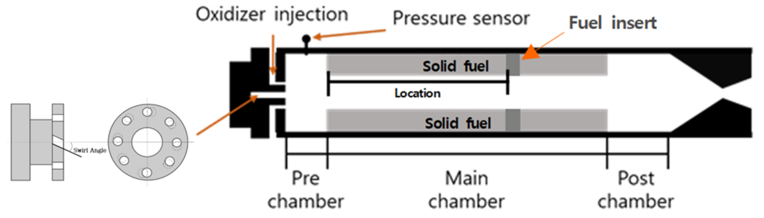
Figure 3 shows the configuration of the hybrid rocket motor used for the combustion tests. The lengths of the pre-chamber and main and post chambers of the apparatus were fixed at 45, 400, and 75 mm, respectively, and the inner diameter was 50 mm for all the tests. A piezo-type sensor (PMP 5074; General Electric, New York, NY, USA) was installed in the middle of the pre-chamber to measure the combustion pressure, and a quartz window was placed in the middle of the post chamber for visualization and heat-release measurements. A photomultiplier tube (PMT) was used to measure the heat-release oscillations (
q′). After proper modifications, one side of the chamber was fitted with a window to visualize the combustion flow in the chamber. Light from the chamber was recorded using a camera (Ex-1; Casio, Tokyo, Japan) and the PMT (H10722; Hamamatsu, Hamamatsu-shi, Japan). The camera and PMT shared the same field of view and were synchronized for both measurements. Data sampling rates are 10 kHz for both measurements. An event-based synchronization technique using LED flashes was used to measure the pressure and for the high-speed image data. Visualization tests were conducted in a completely dark room to eliminate noise interference to the PMT. In addition, bandpass filters at 430 nm, which is the intrinsic wavelength of the CH* radical, were attached to the fronts of the camera and PMT to capture clear images of the combustion reactions.
2.2. Baseline and Test 1
Table 1 summarizes the test conditions of baseline and tests 1 and 2. A baseline test was performed to identify the specific combustion conditions that resulted in instabilities. The baseline case was when the fuel was pure PMMA with LFI occurring during combustion. The fuel insert at the front has the effect of increasing the regression rate, while the fuel insert at the back can alter the boundary layer flow near the surface. In addition, test 1 had a fuel insert located at the rear end of the fuel. The location of fuel insert is measured from the front end of the fuel. During combustion with the fuel insert, the appearance of a small intrusion induced changes in the small-vortex generation near the fuel surface, and this section examines how those changes affected the coupling status between
p′ and
q′ and the BL flows.
Figure 4 shows the trace combustion pressure measured in the baseline and test 1 and the pressure fluctuations in the filtered
p′ in the 350–650 Hz range. Here, the average combustion pressure is ~1310 kPa, and LFI is observed in both cases with very similar combustion characteristics. Nevertheless, a slight delay was measured in the LFI onset time for test 1. In the baseline, the LFI began ~6.5 s after ignition, but in test 1 this was ~8 s when using the fuel insert. As seen in
Figure 4b, the same delay in the onset of instability was observed in the data for the filtered
p′ in test 1. Thus, the amplification of
p′ may be a precursor to LFI occurrence, indicating an appropriate physical connection between them.
Figure 5 sequentially compares cross-sectional images of the inserted fuel used in test 1 and its combustion pressure from ignition to LFI. The test was repeated four times under the same conditions, and each image was taken with shutdown at a different time point. Prior to LFI initiation, a small step appeared on the fuel surface (a) and then decreased gradually (b) before finally disappearing (c). Note that LFI occurred just after the step disappeared. Although the step height was relatively small, it is assumed that its formation and disappearance in the fuel surface is closely related to the delayed LFI occurrence.
A recent study [
4] reported that the formation of positive coupling between
p′ and
q′ is a crucial phase that leads to LFI. Therefore, it is important to monitor changes in the phase difference between
p′ and
q′ during combustion since the formation of positive coupling may be closely related to LFI occurrence. The RI (=
) is a good indicator of the level of positive coupling.
Figure 6 shows the combustion pressures and time variations of the RI in the baseline and test 1. In both cases, the RI began to increase abruptly at the onset of LFI. However, there was little change to the RI in test 1 until LFI initiation, which seems to be suppressed by some factor. Note that test 1 is the case with a fuel insert attached to the end of the base fuel. The fuel insert gradually turned into a small step during combustion, which changed the flow structures near the surface and the characteristic frequencies of the small vortices. Therefore, the delay in LFI initiation is attributed to changes in the flow structure caused by the small step. In particular, the altered flow structure inhibited the generation of
p′ and
q′ in the 500-Hz band, which prevented their positive coupling. However, as the step height decreased, LFI resumed and the RI began to increase suddenly, as shown in
Figure 6b. Therefore, the formation of positive coupling between
p′ and
q′ is a precursor to LFI occurrence. Nevertheless, the physical process of how the formation of positive coupling leads to LFI is yet to be understood clearly.
2.3. Location of Fuel Insert
The results of test 1 confirm that the fuel insert can delay the occurrence of LFI but does not eliminate it completely. The analysis in this section focuses on how LFI occurrence is affected by changes in the fuel-insert location. The first effort is to closely monitor the characteristic frequency of p′ and the phase difference with respect to q′ as functions of the fuel-insert location. In addition, the fuel-insert location that has the greatest impact on controlling the instability is discussed.
It is well known that inserting a diaphragm induces flow circulation behind it, while increasing the fuel regression rate [
7]. Nevertheless, the present study was designed to (i) minimize the increased fuel regression rate, even with the appearance of a small step on the fuel surface, and (ii) change the flow structures only near the surface.
Table 2 summarizes the configuration for each test, such as the fuel-insert location, total fuel consumption, and oxygen-to-fuel (O/F) ratio (replacing the equivalence ratio). Note that the total fuel consumption did not change significantly over all the cases, except for test 5. The fuel consumption was much higher in test 5 since two fuel inserts were used. In addition, test 5 was designed to investigate whether using two fuel inserts improves the controlling effects or suppresses the instability effectively.
2.4. Suppression of Low-Frequency Instability
Test 2 was an additional case designed to significantly improve LFI suppression by simultaneously placing two fuel inserts.
Figure 7 shows the combustion pressures and the phase difference between
p′ and
q′ as measured in this case. The combustion pressure allows relatively stable combustion, even though the fast-Fourier-transform analysis shows that the
p′ and
q′ characteristics are still observed in the 500-Hz band. In addition, the characteristic frequencies of
p′ and
q′ remain completely unchanged and unaffected, as seen in
Figure 8. Nevertheless, the phase difference between
p′ and
q′ becomes π/2 and the coupling status is changed to negative, which results in no periodic amplifications of the RI.
The total fuel consumption in test 2 was 162.6 g, which is the largest increase for all cases by ~7%. It was reported that the phase difference between
p′ and
q′ was determined primarily from the instantaneous equivalence ratio [
4]. The shift to negative coupling between
p′ and
q′ can be considered as the result of further reductions in the O/F ratio (or increased regression rate). Thus, LFI suppression is the result of synergistic effects from the increased fuel consumption using the two fuel inserts (decreased average O/F ratio). If the coupling status between
p′ and
q′ becomes negative, then the periodic amplification of the RI, which is observed only in the case for positive coupling, does not occur. Thus, it is assumed that the upstream flow near the fuel surface was not disturbed. A spectral analysis of the time coefficients for mode 2 was performed to confirm whether there were changes in the BL flow.
2.5. Results and Discussion
The results confirm that using fuel inserts induces the formation of a small step on the surface due to differences in the regression rates of the two materials. This small step affects the flow structures, including small vortices that are closely related to the generation of p′. In test 1, a substantial delay in LFI occurrence was observed along with reduced p′ amplitudes. During the delay, neither periodic amplification of the RI nor oscillations of the BL flow were found. Note that the LFI resumed immediately after the step disappeared. Various tests were performed to investigate how the LFI occurrence is affected by changes in the fuel-insert location. The results show that the delayed LFI occurrence is limited, regardless of the fuel-insert location.
To enhance the controllability of LFI suppression, test 5 simultaneously placed two fuel inserts at the locations from tests 2 and 4. The combustion pressure in test 5 enabled relatively stable combustion, even though p′ and q′ characteristic frequencies in the 500-Hz band were still observed. In addition, these characteristic frequencies were completely unchanged and unaffected. Nevertheless, the phase difference between p′ and q′ became π/2, which changed the coupling status to negative and did not allow periodic amplification of the RI. This shift to negative coupling between p′ and q′ can be considered as the result of further reductions in the O/F ratio. In addition, a spectral analysis of the time coefficients for mode 2 was performed to investigate the changes in the BL flow. Unlike in other cases with LFI, frequency peaks from 15–20 Hz were not observed in test 5.
In summary, the test results confirm that there are physical connections among several processes, such as the coupling status between p′ and q′, the periodic amplification of the RI, and the oscillations of upstream flow identified in mode 2. LFI suppression was possible by disrupting or eliminating the connections among these couplings.
3. Controlling Low-Frequency Instability with a Fuel Insert and Swirl Injection
In this section, oxidizer swirl injection is used rather than placing a fuel insert at the front end to induce the same physical effect disrupting the coupling process obtained in the previous section. In addition, an optimal swirl strength is to be determined not to cause excessive deviations in combustion performance. From a hydrodynamic perspective, not only does oxidizer swirl injection increase the fuel regression rate but also the rotational component changes the flow characteristics including the BL. On the other hand, as combustion progresses, the step created by the fuel insert gradually decreases, thereby eliminating the original intention to change the BL flow, but swirl injection does not induce this drawback. Therefore, using swirl injection with a fuel insert can reduce these side effects by continuously affecting the BL flow, thereby making it a more effective way to control LFI. Moreover, LFI is expected to be suppressed by applying both proper swirl injection and a fuel insert, while minimizing side effects to the combustion system.
3.1. Materials and Methods
Figure 9 shows a schematic of the combustion chamber and swirl injector used for the combustion tests. In all the tests, unless noted otherwise, the oxidizer supply was controlled to remain at 20 g/s. During the tests, data collection and processing were done through data-acquisition boards and the LabVIEW system. The data sampling rate was 10 kHz.
As solid fuels, PMMA was used with an inner diameter of 20 mm and a length of 400 mm, and HDPE—with a slightly lower regression rate than PMMA—was used for the fuel inserts. Since HDPE has a low regression rate, small steps appeared on the fuel surface as combustion progressed, affecting the BL flow in the same way as a diaphragm. Moreover, the appearance of the step intrusion is expected to affect the occurrence of LFI by changing the BL flow.
Table 2 summarizes the test conditions such as the swirl injection angle and the fuel-insert location. Test 6 was a reference case (baseline) in which LFI occurred. As mentioned, the primary objective of this study was to examine how the combination of swirl injection with a fuel insert affects the occurrence of LFI.
LFI is thought to occur as a result of the periodic positive coupling of very weak high-frequency pressure oscillations (
p′) and heat-release oscillations (
q′) [
3,
4,
5]. At this time, the formation of periodic coupling by the two oscillations is the external disturbance that causes the upstream BL flow to fluctuate and is known as the triggering system mechanism leading to the occurrence of LFI. Therefore, LFI could be suppressed if the formation of periodic coupling could be controlled by adjusting the swirl angle and insert location.
As mentioned, this study attempted to change the coupling behavior of the two oscillations
p′ and
q′ using both oxidizer swirl injection and a fuel insert.
Figure 10 compares only the high-frequency components of the two oscillations filtered from test 3. This figure shows that there are some physical correlations between the two oscillations. In particular, the coupling behavior can be understood if we directly compare the time changes of the phase difference of the two filtered oscillations. Moreover, by monitoring the change in the coupling status, it is possible to understand the effect on the occurrence of LFI.
3.2. Fuel Inserts versus Swirl Injection
In previous studies, placing a fuel insert induced various effects, such as the generation of large vortices, an increase in regression rate concentrated near the insert, and a decrease in the average O/F ratio. In particular, it was found that the increase in combustion temperature enhanced the propagation speed of the pressure wave, thereby changing the phase difference between the two oscillations. Therefore, it is expected that LFI can be controlled if the combustion temperature can be changed properly through a swirl injection. To do this, it is necessary to determine the vortex injection angle that induces the same effect of average O/F ratio change as the fuel insert used in the previous section.
Figure 11a shows the temporal variations of the combustion pressure and phase difference between
p′ and
q′ measured in test 4, where the fuel insert was placed 300 mm from the inlet and the swirl injection was also applied. Here, the swirl angle was set to 5°. Note that LFI was still observed in this case even if the swirl injection was applied. The results indicate that it is still necessary to adjust the swirl angle or the location of the second fuel insert to suppress LFI completely.
Figure 11b shows the results of test 6, in which the swirl injection angle was increased by only 1° and the other conditions were kept the same as those in test 4. Compared to the baseline, LFI is still observed, albeit weakened. In addition, the phase difference between
p′ and
q′ remains less than π/2, causing the formation of positive coupling. Therefore, if additional effective methods other than the swirl angle are available, then it is necessary to use them to change the phase difference further.
Next, an attempt was made to shift the phase difference towards π/2 by increasing the swirl injection angle and moving the fuel insert to the appropriate location. Test 7 was the case of adjusting the fuel-insert location from 300 to 310 mm. By doing this, it was expected that the rotational component caused by the swirl injection would be reduced further, and the phase difference between the two oscillations can be increased to ~π/2.
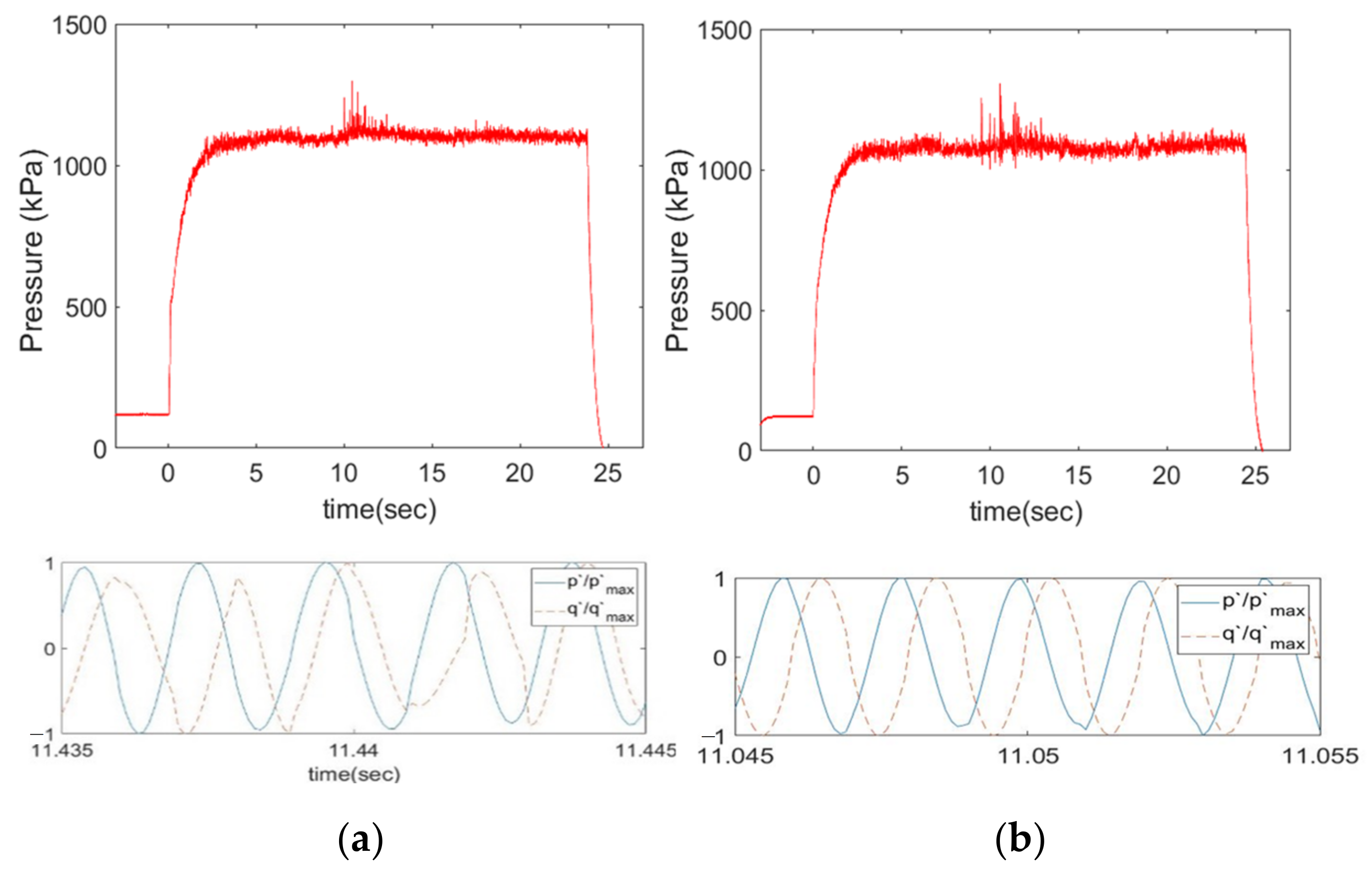
Figure 12 compares the temporal variation of combustion pressure and filtered high-frequency band (400–600 Hz,
p′) oscillation measured in tests 3 and 7 and the pressure oscillations in the stable and unstable regions are compared. Test 7 was designed to suppress LFI with the simultaneous use of swirl injection (6°) and a fuel insert (310 mm). As can be seen, the average pressure remained at the same level as in test 3, and LFI was properly suppressed. During the stable combustion (4–7 s), the amplitude of the high-frequency pressure oscillation (
p′) was very weak in both cases, while during the unstable combustion (10–13 s), relatively strong oscillations were observed. In particular, in test 3, the high-frequency pressure oscillations were observed to form very strong peaks in the shape of a delta function at ~16–18 Hz. By contrast, in test 7, in which LFI was suppressed, the combustion pressure changed from oscillations with strong periodic peaks in the shape of a delta function to weak ones with amplitudes reduced by ~50%.
As shown in
Figure 13, combustion instability was properly suppressed in test 7, in which swirl injection with an appropriate strength and a fuel insert were used together. In other words, it is possible to stabilize combustion by shifting the phase difference of the two oscillations induced by introducing fluid-dynamic modifications (swirl injection and a fuel insert). In this regard, this study confirmed again that LFI can be suppressed if negative coupling between the two oscillations is induced by hydrodynamic modifications using swirl injection and a fuel insert. In addition, it was confirmed that thermoacoustic coupling between high-frequency oscillations can lead to external disturbances with low-frequency features similar to those of thermal lag.
In summary, the suppression of combustion instability was attempted using both swirl injection and a fuel insert as used in the previous section. Unlike previous studies that used only fuel inserts, applying an excessive swirl strength had the side effect of intensively increasing the regression rate only near the inlet, and it is necessary first to determine the appropriate swirl strength. Considering that the average O/F ratio was 1.92 with the fuel insert placed at the front end, the O/F ratio of 1.91 at a swirl angle of 5° in this test shows that both methods are equally effective in controlling the O/F ratio.
3.3. Combustion Performance with Swirl Injection
In this study, the primary goals were (i) to suppress the occurrence of LFI and (ii) to keep the fluctuations in combustion performance to a minimum despite the hydrodynamic modifications. Reference [
5], which studied the effect of swirl injection on the occurrence of LFI, confirmed that combustion becomes stable as the swirl intensity increases. However, the rotational component in swirl injection severely increases the local regression rate near the fuel inlet. Therefore, to minimize the induced combustion changes, it is first necessary to quantify the changes in combustion performance that occur when using swirl injection and fuel inserts. The average combustion pressure, the average O/F ratio, and the axial distribution of the regression rate appear to be the most suitable variables for quantifying the change in combustion performance.
Figure 14 compares the trajectories of combustion pressure in tests 7 and 8. Note that in test 8, the swirl injection angle was increased to 9° and no fuel insert was placed. As can be seen, despite the successful control of LFI occurrence in both cases, the average combustion pressure in test 7 was significantly lower than that in test 9, in which both swirl injection and a fuel insert were used. Therefore, it has been found that applying swirl injection with a fuel insert can suppress LFI occurrence while minimizing the negative impact on combustion performance.
Table 3 compares the combustion performance including the average O/F ratio and regression rate measured in tests 7 and 8. Compared to test 3, the average combustion pressure increased by 4% in test 8 and by 11% in test 7. In test 8, the decrease in the average O/F ratio was greater than that in test 7, indicating that the increase in the regression rate of the fuel was heavily concentrated only near the front end. Thus, test 8 appears to represent optimal combustion conditions under which LFI is suppressed adequately and variations in combustion performance are kept to a minimum.
3.4. Results and Discussion
In hybrid rocket combustion, since the rotational component affects the BL flow, the oxidizer swirl injection is generally used to stabilize the combustion. However, with the increasing swirl strength, there is a side effect of changing the combustion performance too much. This study attempted to control the occurrence of LFI by applying both the appropriate intensity of swirl injection and a fuel insert, while also minimizing variations in combustion performance. Consequently, it was confirmed that LFI was suppressed successfully when the swirl angle was 6° and the fuel insert was located at 310 mm. In addition, when both swirl injection and a fuel insert were used, the combustion performances in terms of combustion pressure, O/F ratio, and fuel regression rate showed minimal variation compared to those of the baseline.
4. Conclusions
The combustion pressure in hybrid rockets usually oscillates in the low-frequency band, typically less than 100 Hz, and the origin of these pressure oscillations is attributed to the thermal lag of solid fuels. The occurrence of LFI seems to be related to the interaction of many complicated physical processes such as vortex shedding, BL oscillation, and additional combustion in the post chamber. Nevertheless, it is presumed to be a typical example of thermoacoustic coupling caused by vortex impingement.
Previous combustion studies using premixed mixtures reported that when the vortices shed from the backward-facing step collide with the wall, thermoacoustic coupling occurs under certain combustion conditions, leading to combustion instability. Several numerical results confirmed that in hybrid rockets, although the BL is lifted by the fuel evaporation flow, the pattern of vortex shedding and impingement is very similar to that observed in the flow behind the backward-facing step. Therefore, the thermoacoustic coupling of the low-frequency band due to the vortex shedding and impingement and the disturbed BL flow can be thought to lead to the occurrence of LFI. Moreover, the BL adjustment in response to external perturbations is a crucial process for initiating LFI.
In this regard, two combustion tests were performed to examine which physical processes are most sensitively connected to the occurrence of LFI. In the first test, two fuel inserts were used to influence BL formation, vortex shedding at the end of the fuel, and vortex impingement in the post chamber. In the second test, oxidizer swirl injection was used rather than placing a fuel insert at the front end to induce the same physical effect. Using swirl injection with a fuel insert can alleviate side effects by continuously affecting the BL flow, thereby making it a more effective way to control LFI.
The first test was aimed at understanding the causes of heat-transfer oscillation in the BL, which is a critical precursor to LFI, and to suppress LFI using fuel inserts. The results confirmed that there are physical connections among several processes, such as thermoacoustic coupling between p′ and q′, periodic amplification of the RI, and oscillations of the upstream flow. LFI could be suppressed by disrupting or eliminating the connections among these physical processes.
The second test was aimed at controlling the occurrence of LFI by applying both an appropriate intensity of swirl injection and fuel insert while minimizing variations in combustion performance. The results showed that LFI was suppressed successfully when the swirl angle was 6° and the fuel insert was located at 310 mm. Moreover, when both swirl injection and a fuel insert were used, the combustion performances in terms of combustion pressure, O/F ratio, and fuel regression rate showed minimal variation compared to those of the baseline.
In this study, it was confirmed that combustion instability can be suppressed by changing the boundary layer flow near the fuel surface with a fuel insert or by increasing the equivalence ratio with swirl injection. In this regard, the result of Lee et al. [
4] reported that the phase difference between p′ and q′ in hybrid rocket combustion is closely related to the change in the equivalence ratio. Therefore, it is considered that the change in boundary layer flow induced by a fuel insert or swirl injection and an appropriate increase in O/F ratio are the critical factors suppressing combustion instability.


