Article

Wind Tunnel Studies on Hover and Forward Flight Performances of a Coaxial Rigid Rotor

1
School of Aerospace Engineering, Tsinghua University, Beijing 100084, China
2
Low Speed Aerodynamics Institute, Aerodynamics Research and Development Center, Mianyang 621000, China
*
Author to whom correspondence should be addressed.
Aerospace 2021, 8(8), 205; https://doi.org/10.3390/aerospace8080205
Submission received: 6 June 2021 / Revised: 9 July 2021 / Accepted: 22 July 2021 / Published: 28 July 2021
(This article belongs to the Special Issue Helicopter Aerodynamics)

Abstract

:
The aerodynamic performance of a reduced-scale coaxial rigid rotor system in hover and steady forward flights was experimentally investigated to gain insights into the effect of interference between upper and lower rotors and the influences of the advance ratio, shaft tilt angle and lift offset. The rotor system featured by 2 m-diameter, four-bladed upper and lower hingeless rotors and was installed in a coaxial rotor test rig. Experiments were conducted in the Φ3.2 m wind tunnel at China Aerodynamics Research and Development Center (CARDC). The rotor system was tested in hover states at collective pitches ranging from 0° to 13° and it was also tested in forward flights at advance ratios up to 0.6, with specific focus on the shaft tilt angle and lift offset sweeps. To ensure that the coaxial rotor was operating in a similar manner to that of the real flight, the torque difference was trimmed to zero in hover flight, whilst the constant lift coefficient was maintained in forward flight. An isolated single-rotor configuration test was also conducted with the same pitch angle setting in the coaxial rotor. The hover test results demonstrate that the figure of merit (FM) value of the lower rotor is lower than that of the upper rotor, and both are lower than that of the isolated single rotor. Moreover, the coaxial rotor configuration can contribute to better hover efficiency under the same blade loading coefficient ( C T / σ ). In forward flight, the effective lift-to-drag (L/De) ratio of the coaxial rigid rotor does not monotonously change as the advance ratio increases. Increases in the required power and drag in the case with a high advance ratio of 0.6 leads to the decreasing L/De ratio of the rotor. Meanwhile, the L/De ratio of the rotor is relatively high when the rotor shaft is tilted backward. The increasing lift offset tends to result in reduced required rotor power and an increase in the rotor drag. When the effect of the reduced rotor power is greater than that of the increased rotor drag, the L/De ratio increases as the lift offset increases. The L/De ratio can benefit significantly from lift offset at a high advance ratio, but it is much less influenced by lift offset at a low advance ratio. The forward performance efficiency of the upper rotor is poorer than that of the lower rotor, which is significantly different from the case in the hover flight.

1. Introduction

One of the future helicopter development directions is to achieve high-speed flight. It has been challenging for a conventional helicopter to fly faster than 360 km/h because of the lift that needs to be balanced on the advancing and retreating sides of the rotor. As the forward speed of the helicopter increases, the airflow over the retreating blade becomes relatively slow, which together with the increased angle of attack, can cause lift stall and loss. In contrast, the airflow over the advancing blade is relatively fast. When the velocity of the airflow at the blade tip approaches the sound velocity, transonic drag begins to rise dramatically [1,2].
Developed based on the advancing blade concept (ABC), coaxial rigid rotors are typically featured by a pair of coaxial, counter-rotating rotors. During high-speed forward flight, the lift is mainly borne by the advancing side of the rotor disk, the coaxial rotors balance the rolling moment and counter torque, and the stall on the retreating blade would then be much less important. The rotor speed is lowered to keep the advancing blade tip below the sound barrier [3,4]. This would result in an enhanced high-speed forward flight capability and thus an improved cruise efficiency whilst retaining the hover efficiency and maneuverability of the helicopter. Coaxial rigid rotors have aerodynamic characteristics that are different from conventional edgewise rotors, such as lift offset and coaxial rotor aerodynamic interference. In this context, it is imperative for the theoretical research and engineering design of coaxial rigid rotors to implement a coaxial rigid rotor wind tunnel test to study rotor lift offset and mutual interference of coaxial rotors.
Sikorsky conducted a series of full-scale trial of coaxial rigid rotors in the 40- by 80-foot wind tunnel in the 1970s [5] and subsequently conducted an XH-59A rotorcraft wind tunnel test in the 1980s [6]. Despite the progress in evaluating the performance and load characteristics of the coaxial rigid rotor, these two tests did not characterize the aerodynamic performances of the upper and lower rotors separately.
In recent years, an increasing number of wind tunnel tests have been implemented on coaxial rigid rotors, owing to the development of X2, S97 and SB1 high-speed helicopters by Sikorsky Company in the United States. Moreover, the recently developed coaxial rotor test rigs have independent balance measurements for the upper and lower rotors. Using the coaxial test rig developed by Maryland University, researchers were able to measure static and dynamic loads for upper and lower rotors separately by two modified six-component load cells, each of which were mounted directly below the upper or lower rotor. Cameron et al. [7,8,9] investigated the aerodynamic performance and load of the rotor in both hover and forward states by implementing the lift offset test on single and coaxial rotors. In forward flight, the effective lift-to-drag (L/De) ratio of the rotor was found to increase with escalating advance ratio and lift offset. More specifically, an increase in the lift offset could contribute to a maximum increase of 40% in the L/De ratio. Vibratory loads also increased with the advance ratio, with the largest loads in the two- and four-per-revolution harmonics. However, the rotors were maintained at a series of constant collective pitches and, therefore, the overall lift equilibriums of the helicopter were not satisfied. Moreover, data influenced by the shaft tilt was not included. Both 0.303 S-97 and 0.2 S-97 scale powered models were tested in the National Full-Scale Aerodynamics Complex (NFAC) 40 by 80-foot section using the Sikorsky Aircraft Coaxial Rotor Test Rig (CARTR), to examine the rotor performance and rotor/fuselage interference [10,11]. However, these experimental results have not been made public.
Aircraft flight control strategies are expected to be improved by better understanding the lift offset and coaxial rotor interference as well as the rotor aerodynamic performance as a function of tilt angle. This improvement would lead to enhanced efficiency and expanded operational envelopes. In this way, progress needs to be made in improving the knowledge of the aerodynamic performance of coaxial rigid rotors under real operation states in high-speed flights.
Although some test efforts have been made on the aerodynamic performances of the coaxial rigid rotor, there is a lack of upper and lower rotor performance data measured separately and simultaneously operating close to the real flight state of the high-speed compound helicopter. This research aims to describe and evaluate the effects of lift offset, rotor attitude angle and the aerodynamic interference on rotor performance at hovering and forward trimmed steady-state operating points. A coaxial rotor test rig was developed by China Aerodynamics Research and Development Center (CARDC) to investigate the aerodynamic characteristics of the coaxial rigid rotor. The coaxial rigid rotor system was measured in various conditions with different wind speeds, lift offsets and tilt angles, followed by the comparison with the performance of a single isolated rotor at the same pitch at both hover and forward flight states.

2. Experimental Setup
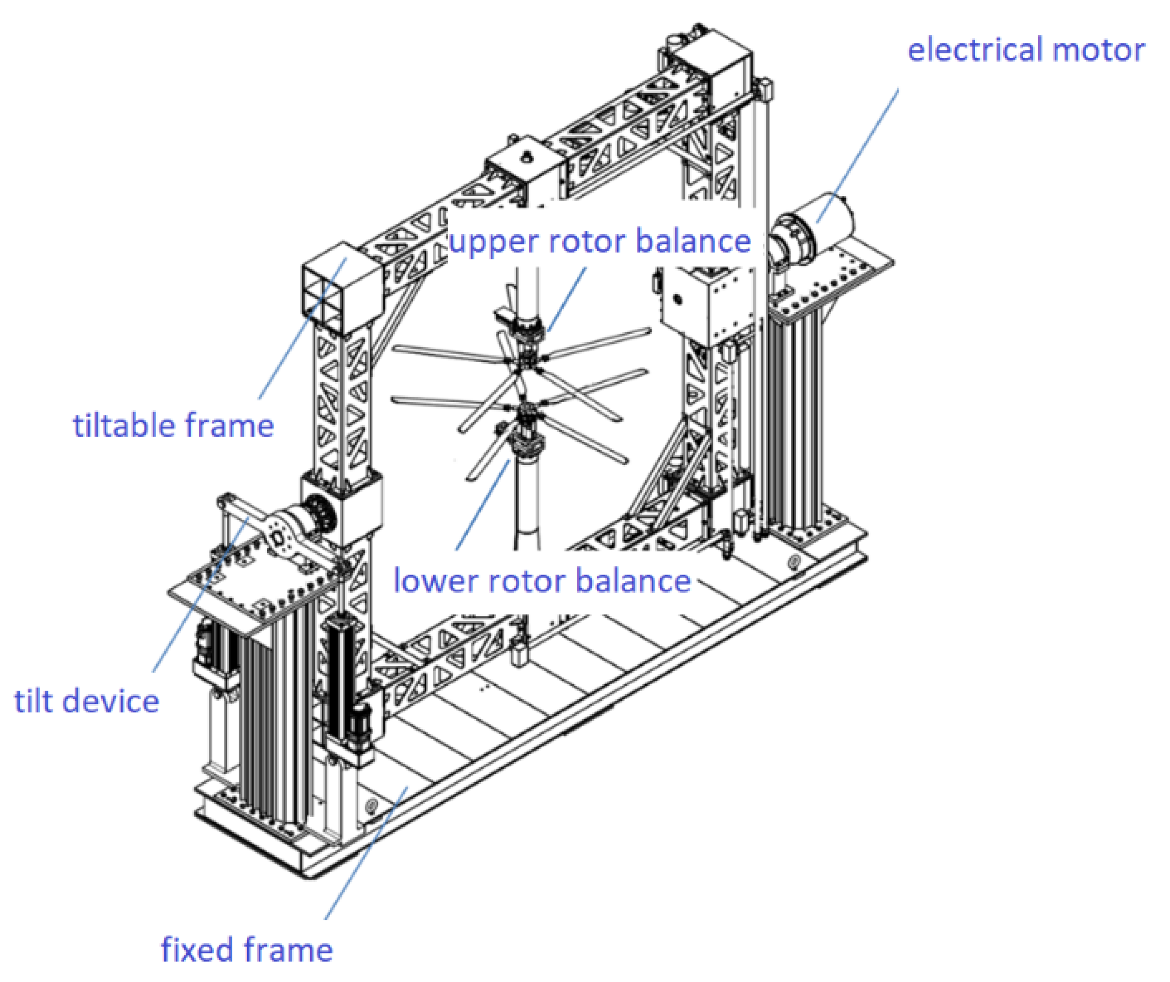
2.1. Test Apparatus

The coaxial rotor test rig used in the present study was developed by CARDC (Figure 1). The three major components of the test rig, namely the drive system, rotor control system and the balances were mounted on a specially-designed, tiltable rectangular frame that was articulated with the fixed platform and thus, the shaft tilt angle of the upper rotor varied synchronously with that of the lower rotor. The coaxial rotor was powered by a 150 kW electric motor and the coaxial transmission comprised five bevel gearboxes mounted on the tiltable rectangular frame, which led to the counter-rotation of upper and lower rotors.
It is common to have the upper rotor shaft pass through the lower rotor shaft in the coaxial helicopter. However, this was not the case in the test rig of the present study. More specifically, the upper and lower rotors were separated in space, which provides convenience for the arrangement of the balances and the rotor control systems. In this way, both the upper and lower rotors had a set of independent swash plates, a rotor balance and torque meter. The arrangement of balances as well as the mechanical components of the rotor control systems were similar to that of most conventional single-rotor test rigs. For each rotor system, it was mounted on the top of the balance upper plate and comprised a swash plate and three electrical actuators (Figure 2). As both the upper and lower rotors were equipped with rotor control devices, the collective and cyclic pitch of each rotor can be controlled independently.
Two five-component rotor balances and two torque meters with flex couplings were used to measure the forces and moments of the upper and lower rotors. The rotor balances measured lift, drag and side forces as well as pitching and rolling moments of upper and lower rotors separately. Torque meters were connected on the flex coupling between the rotor shafts and the driveshafts to measure rotor torque. Electrical signals from each rotating torque meter were transmitted through slip rings that were located at the bottom of the rotor gearbox. Table 1 lists the general capabilities and static load accuracies of rotor balances and torque meters as measured during the calibration.
The forward flight test was conducted in the Φ3.2 m, closed-return wind tunnel at CARDC, which had an opened 3.2 m diameter circular test section and a maximum speed of 105 m/s. Figure 3 shows the test rig installed in the wind tunnel.

2.2. Test Model and Procedure

The test employed a pair of 4-blade rigid rotors. The upper rotor rotated in the counterclockwise direction and the lower rotor rotated in the clockwise direction. The rotor blades have a rectangular blade planform. The airfoil at 18% radius was a NACA 0026 airfoil tapering in thickness to a NACA 0020 airfoil at 40% radius. This transitioned to a NACA 0012 airfoil at 56% radius which was held constant to the tip. The solidity of this coaxial rotor was 0.178, and the solidity of the coaxial rotor is defined the same way as for a single rotor:
σ = bc π R
where b, c and R is the total number of blades, blade chord and rotor radius, respectively. The coaxial rotor had twice the solidity of the single rotor in this research. Other parameters are summarized in Table 2.
Their first-order flapping frequency and lagging frequency were 1.698 and 3.248 times the nominal rotational frequency, respectively. The blades were attached rigidly to the hubs with only a feathering bearing. The counter-rotating coaxial rotor system could react to the large rolling moment that was caused by the lift offset on both the upper and lower rotors. Figure 4 presents the fan plot of the first modes.
The rigid coaxial rotor pitch control variables were divided into two categories in this wind tunnel test. The first category was functional in providing normal helicopter main rotor control, inducing coupled collective pitch ( θ 0.7 ), coupled longitudinal cyclic pitch ( A 1 ) and coupled lateral cyclic pitch ( B 1 ), which are defined by Equations (2)–(4), respectively. The second category helped in ensuring the force offset capability by providing the ability to vary differential rotor loading and lift distribution, including differential collective pitch ( θ 0.7 ), longitudinal cyclic pitch ( A 1 ) and lateral cyclic pitch ( B 1 ), which are defined by Equations (5)–(7), respectively.
θ 0.7 = θ 0.7 up + θ 0.7 lo 2
A 1 = A 1 up + A 1 lo 2
B 1 = B 1 up B 1 lo 2
θ 0.7 = θ 0.7 up θ 0.7 lo 2
A 1 = A 1 up A 1 lo 2
B 1 = B 1 up + B 1 lo 2
where θ 0.7 up , A 1 up , and B 1 up are the collective, longitudinal cyclic and lateral cyclic pitches of the upper rotor, respectively, whereas θ 0.7 lo ,   A 1 lo and B 1 lo are the counterparts of the lower rotor, respectively.
As illustrated in Figure 5, the upper rotor rotates in a counter-clockwise direction, whereas the lower rotor rotates in the clockwise direction. Hence, the position of the advancing side of the upper rotor is opposite to that of the lower rotor. Actual blade pitch motions θ   ( Ψ ) of upper and lower rotors are presented in Equations (8) and (9), respectively. Here, A 1 up and B 1 up are the longitudinal and lateral cyclic pitch of the upper rotor, respectively, which can be numerically expressed as A 1 + A 1 and B 1 + B 1 , respectively. Similarly, A 1 lo and B 1 lo are the longitudinal and lateral cyclic pitch of the lower rotor, respectively, which are numerically equivalent to A 1 A 1 and ( B 1 B 1 ) , respectively. Γ is the phase lag and is normally set close to 90° in an articulated rotor. The rotor used in this test has a high flap wise stiffness, blade first order flapping and lagging mode natural frequencies are higher than the XH-59A rotor, which is approximately 1.4/rev for both parameters [3]. In a full-scale wind tunnel test of the XH-59, the rotor control phase lag is set to 0° [5,6] and the test results indicate that there is little or no mutual coupling between the coupled longitudinal cyclic pitch ( A 1 ) and coupled lateral cyclic pitch ( B 1 ) controls [5].Therefore, the force to the displacement phase lag of the rotor used in this test is extremely small. In addition, the result of balances measured is used as feedback to trim the rotor in this test and the precise value of the phase angle of the rotor could be redundant. The value used in current tests is Γ = 0 ° . Thus, the blade pitches motion in Equations (8) and (9) differs by 90° from the conventional rotor [1]. In the case, with no differential control, the application of a positive A 1 can enable the blade pitch of each rotor to increase at Ψup = 0° and Ψlo = 0° simultaneously, which will cause the thrust vector of the coaxial rotor to tilt forward. In contrast, in the case of pure B 1 control, the maximum pitch angles occur at Ψup = 270° for the upper rotor and Ψlo = 90° for the lower rotor, which causes the thrust vector of the coaxial rotor to tilt to the right.
θup = θ0.7up + A1up · cos(Ψup + Γ) – B1up · sin(Ψup + Γ)
θlo = θ0.7lo + A1lo · cos(Ψlo + Γ) – B1lo · sin(Ψlo + Γ)
The wind tunnel test procedure was to set the desired rotor rotational speed, tilt angle and wind speed. Thereafter, the rotor trimming procedure was initiated, which targeted the lift of the rotor equivalent to the aircraft weight, the torque offset of the upper and lower rotors, the hub pitch and roll moments of the coaxial rotor and the specified lift-offset value. The trimming procedure was as follows: the lift lateral displacement control ( B 1 ) changed the lift offset to the specified value and the lift longitudinal displacement control ( A 1 ) was maintained at approximately zero during the test. Coupled collective pitch ( θ 0.7 ) and coupled cyclic pitch ( A 1 and B 1 ) were adjusted to provide the lift coefficient of the coaxial rotor to 0.012, accompanied by adjustment of the hub moments to approximately zero. In the hover and low-speed forward test states, differential collective pitch ( θ 0.7 ) was implemented to adjust the rotor torque difference to approximately zero. As has been demonstrated in previous experimental and computational studies, the yaw control power as produced by θ 0.7 is low in high-speed flight [5], and the coaxial rigid rotor helicopter does not involve differential collective pitch in such a regime [12]. Therefore, the rotor torque trimming procedure was only implemented in the μ range of 0–0.15.
The data of the balances, including two rotor balances and two torque meters, were acquired synchronously under the 64 per-revolution trigger of the encoder azimuth sign in each test state during a period that was equal to 80 rotations of the rotor. The whole data were first divided into eight segments, each of which was implemented with average alignment to finally obtain the time average and harmonic values.
The thrust coefficient of the rotor is defined as:
C T = T ρ ( ω R ) 2 π R 2
where T , ω R and R are the thrust, tip speed and radius of each rotor, respectively.
The power coefficient of the rotor, CP, is defined as:
C P = P ρ ( ω R ) 3 π R 2
where P is the power of each rotor.
The figure of merit (FM) to evaluate the rotor hover efficiency is defined as:
FM = C T 1.5 2 C P
The L/De to evaluate the forward flight efficiency of the rotor is defined as:
L / De = C L C P μ + ( C D C D   hub )
where C L , C D   hub , and C D are the lift force coefficient, the drag force coefficient of the hub and the drag force coefficient of the rotor, respectively. They are all nondimensionalized by dividing the same denominator as that of Equation (9). In some other studies, L/De is also written as the ratio of the rotor lift force to the effective drag, which is calculated from the power expended (i.e., D = P/V∞, where P is the actual power) [13]. Equation (10) is preferred for use within this research to measure the aerodynamic efficiency for forward flight because it takes into account the effect of blade drag force and has been used in the aerodynamic design evaluation of the X2 main rotor blade [14].
When calculating the force and the moment coefficient of the coaxial rotor, the force and moment used in the numerator are obtained by adding the measurement results of the upper and lower rotors, and the radius R used in the denominator is the radius of a single rotor.
Lift offset is the effective lateral offset of the lift vector relative to its hub center for each rotor. There are different definitions in the existing literature [5,6,7,8,9,13]. This paper adopted the definition by Paglino and Beno [5], which evaluated the XH59A rotor performance in their wind tunnel test research. More specifically, they defined the lift offset as the ratio of the lift center displacement of the upper rotor to its radius, which can be determined as:
LOS = M x   up L up R
where M x   up and L up are the rolling moment and lift of the upper rotor, respectively.

2.3. Experimental Content

The experimental campaign was designed to explore specific aerodynamic performance features of the coaxial rigid rotor configuration. Two sets of experiments were performed: hover and forward flight tests, both of which included a comparison of the coaxial and isolated single rotors.
The nominal rotating speed of the rotor was 1860 rpm. In the hover test, a sweep in the coupled collective pitch was made and the zero torque trim for the coaxial rotor was adapted to be compatible with the real operation status. Moreover, the performance of the isolated single rotor was evaluated by increasing its collective pitch. During the wind tunnel test, the majority of the data were acquired through shaft angle, lift offset and wind speed sweeps at the rotor speed of 1860 rpm. To attain a higher advance ratio, a test at the rotation speed of 1100 rpm was also conducted and the advance ratio reached a maximum of 0.6.

3. Results and Discussion

3.1. Rotor Hover Performance

Efforts were made to compare the hover performance of the coaxial rotor with that of the isolated single rotor at the nominal rotation speed of 1860 rpm under different collective pitches. The torque difference of the coaxial rotor was trimmed by the differential collective pitch to approximately zero. The collective pitch of the lower rotor was slightly larger than that of the comparable upper rotor throughout this trim operation. In particular, the collective pitch of the lower rotor was approximately 0.27° higher than that of the upper rotor, when the upper rotor reached its maximum collective pitch value of 13°.
Figure 6 compares the power and thrust coefficients of the upper and lower rotors with the data measured from the isolated single rotor to investigate the interactional effect on the performance of the upper and lower coaxial rotors. As shown in Figure 6, considering the differences in the collective pitch of upper, lower and isolated single rotors are small, thus the presented relationship between each rotor is consistent with existing experimental results that the upper and lower rotors had the same collective pitch controls [7]. The thrust coefficients of the upper and lower rotors under the coaxial rotor condition are lower than that of the single isolated rotor at the same power consumed, due to the interference between the upper and lower rotors that causes the rotor efficiency to decrease as the rotor inflow increases. The thrust generated at the lower rotor is less than that of the upper rotor. More specifically, the hovering aerodynamic efficiency of the lower rotor is lower than that of the upper rotor. Based on the Momentum Theory developed by Leishman [1] that has been utilized in optimizing the aerodynamic design of a coaxial rotor [15,16,17,18] or propeller [19] in hover and axial flight conditions, the inflow of the lower rotor not only contains its own induced velocity but also the wake of the upper rotor, thus resulting in reduced efficiency. The same trend was obtained by Syal for a coaxial rotor using a free vortex method [20].
The FM value of the single isolated rotor first increases as the collective pitch rises, reaching its maximum value of 0.59 (Figure 7). This maximum value is close to that of earlier rotors with similar solidity [21] but lower than that of newer rotors as the blades of this rotor do not have modern airfoils and advanced tip shapes. After attaining the maximum FM value, it decreases as the collective pitch further increases. In contrast, the FM value of the coaxial rotor does not show a decreasing trend within this test region. Moreover, the coaxial rotor configuration contributes to a better hover efficiency under the same blade loading coefficient ( C T / σ ), demonstrating the beneficial effect of the coaxial configuration on the hover performance.

3.2. Forward Flight Rotor Performance

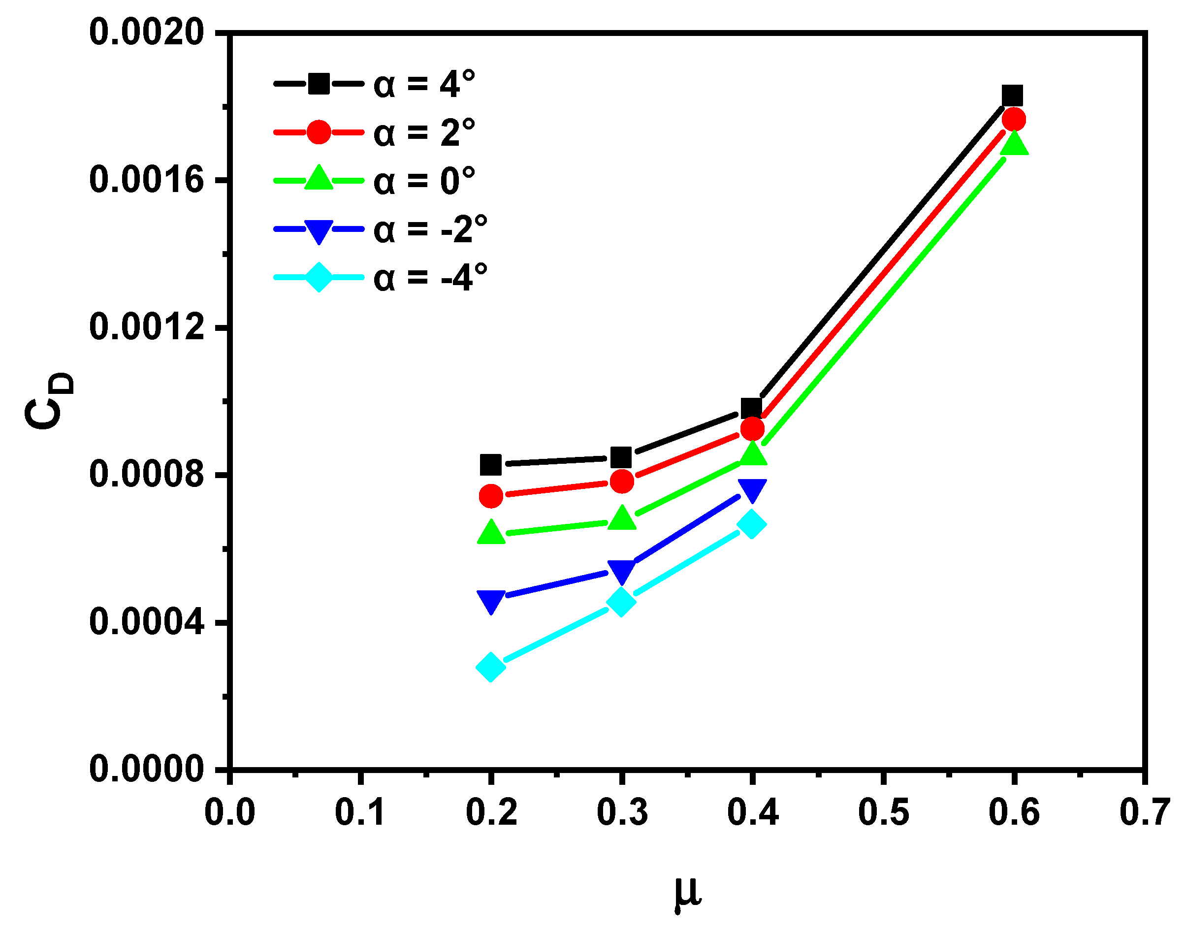
3.2.1. Tilt Angle Sweep Rotor Performance

It generally requires operating the rotor at a proper shaft angle to improve the forward flight aerodynamic efficiency. Therefore, shaft tilt sweeps were conducted for different advance ratios in this research. Figure 8, Figure 9 and Figure 10 show the L/De ratio, power and drag coefficients of the coaxial rotor as a function of the advance ratio for different shaft tilt angles at rotation speeds of 1860 rpm, respectively. Owing to the wind speed and the drag force capability of rotor balance limits, the maximum advance ratio at this rotor rotation speed was 0.4. A sweep of the shaft tilt angle ranging from −4° to 4° was implemented for each advance ratio. Figure 11, Figure 12 and Figure 13 present the higher advance-ratio data obtained by implementing a lower rotation speed of 1100 rpm. At this lower rotation speed, only zero and positive tilt angles were performed when the advance ratio exceeded 0.4. All the aforementioned tests were conducted with the lift coefficient of the coaxial rotor trimmed to 0.012, the rolling and pitching moment trimmed to 0, and the lift offset values maintained at 0.25.
As shown in Figure 8 and Figure 11, the L/De ratio of the rotor first rapidly increases in the advance ratio range of 0.1–0.3, then slowly increases in the advance ratio range of 0.3–0.4 and starts to reduce as the advance ratio reaches 0.6. The power coefficient follows the inverse trend as L/De (Figure 9 and Figure 12). Meanwhile, the drag force coefficient presents overall increasing trends with the enhancing advance ratio in the low shaft tilt angle conditions, whereas it falls in the advance ratio range of 0.2–0.3 in the high shaft tilt angle conditions (Figure 10). An abrupt increase in the drag force coefficient occurs at an advance ratio of 0.6 (Figure 13).
The required power of the coaxial rotor comprises the induced and profile power. It is well known from momentum theory that the induced power decreases as the advance ratio increases, and it is the primary component of the required power in low-speed flight [1]. Therefore, the total power shows a decreasing trend and correspondingly, the L/De ratio increases in the low to moderate advance ratio region. The profile power is required to overcome viscous losses at the rotor, and it scales with the advance ratio as a result of the strengthening of the blade profile drag. When the advance ratio increases to 0.6, the drag and the required power of the coaxial rotor are significantly increased, due to the expansion of the reverse flow region on the retreating side as well as the compressibility effect region on the advancing side, leading to the drop of the L/De ratio.
The coaxial rigid rotor forward performance varies with the changing shaft angle similar to conventional edgewise rotors [22,23,24] because tilting the shaft into the wind (-a) increases the power and thus, causes a decrease in the L/De ratio. This effect is due to the greater upwash on the whole rotor disc resulting from the back tilt of the shaft, which increases the attack angle of the blade elements. Although the forward tilt of the rotor shaft can provide forward thrust components to counteract the rotor drag, it also increases power requirements. Therefore, it can be inferred that an ABC compound helicopter does not need to make the nose pitch down in the level flight, since it uses an auxiliary propulsion system to overcome the drag of the helicopter. This permits the rigid coaxial rotor to operate in a more efficient attitude angle.

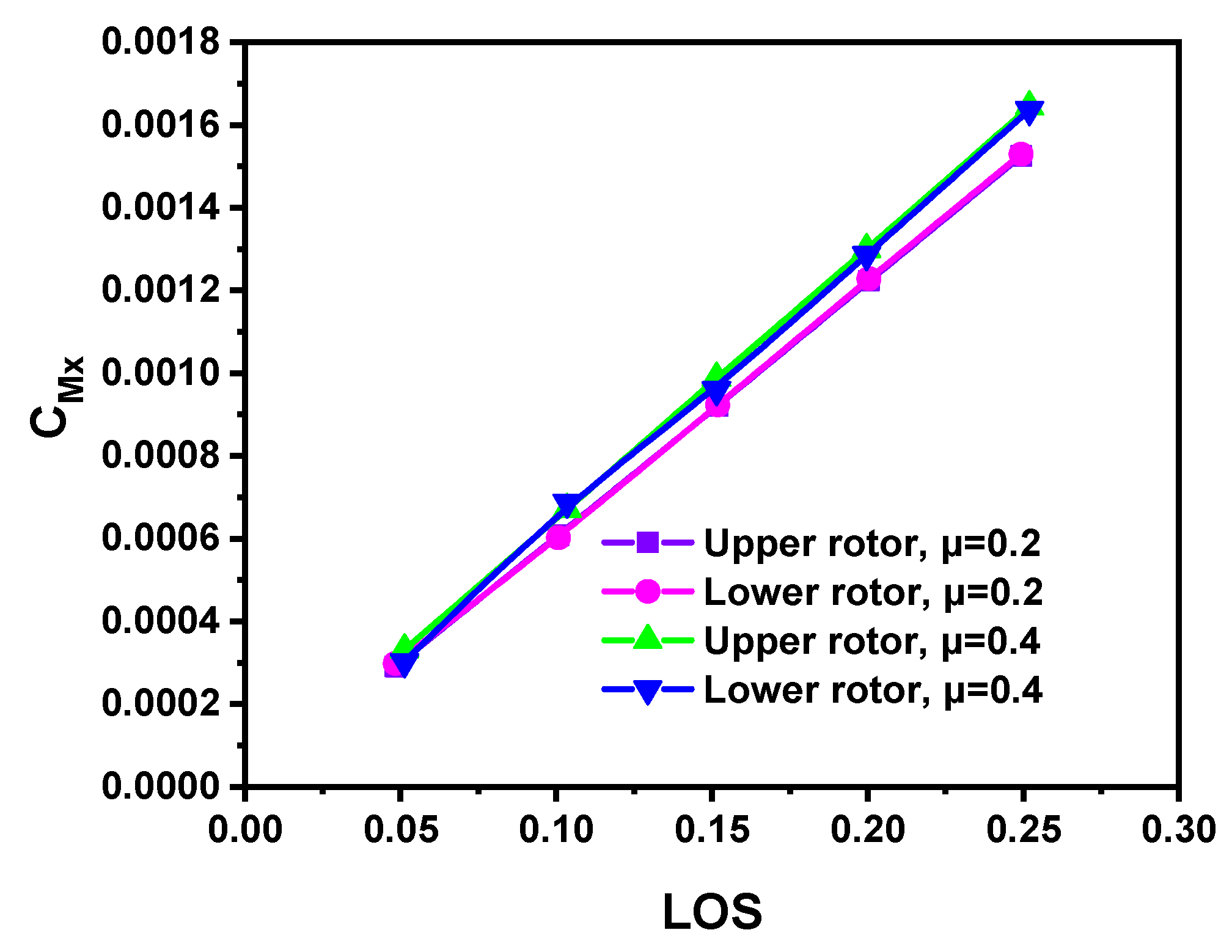
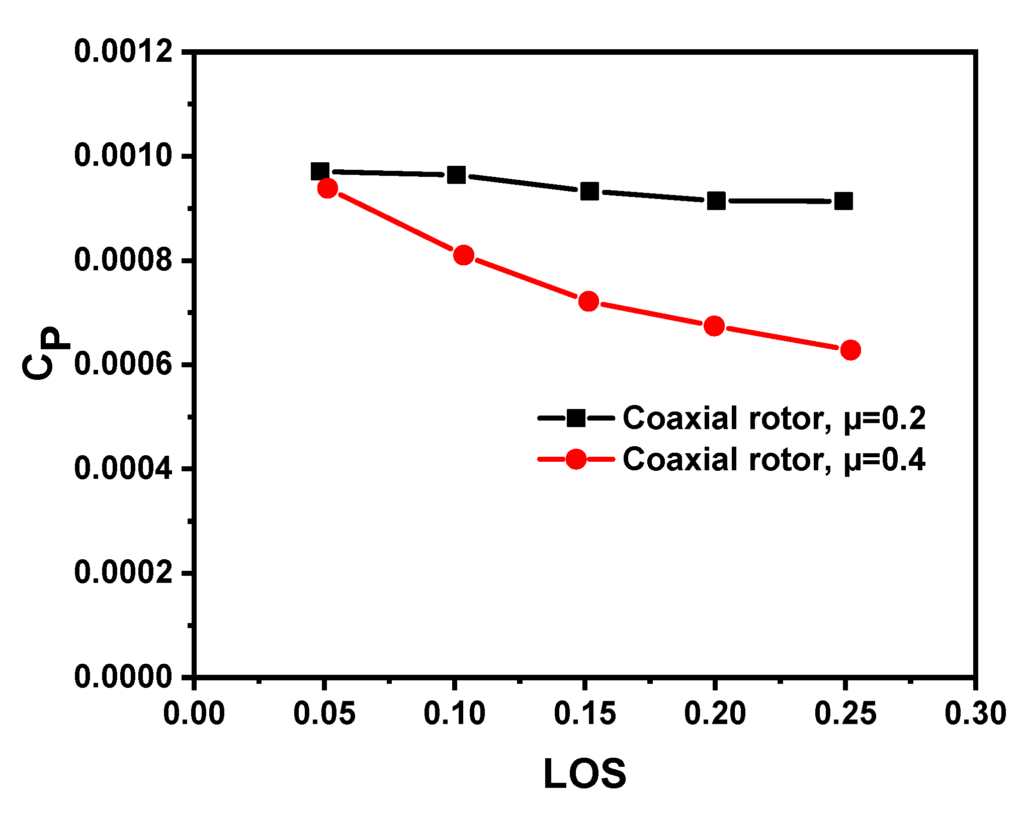
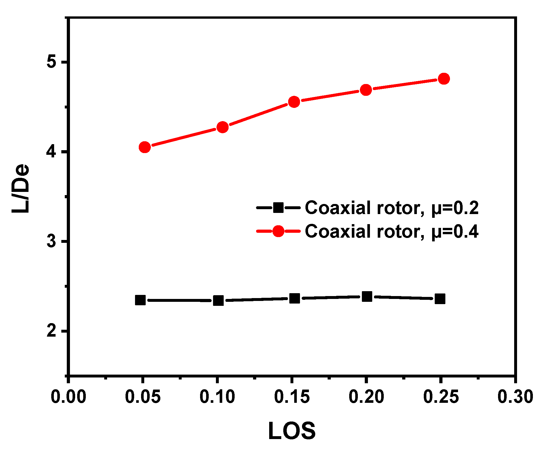
3.2.2. Lift Offset Sweep Rotor Performance

To investigate the influence of the lift offset on the performance of the rigid coaxial rotor, a sweep of lift offset was conducted at advance ratios of 0.2 and 0.4, a rotation speed of 1860 rpm, a shaft angle of 2° and a coaxial rotor lift coefficient of 0.012. As demonstrated in Figure 14, the rolling moment coefficient of each rotor proportionally increases with the lift offset as expected, and the rolling moment magnitude of the upper rotor is similar to that of the lower rotor, thereby providing the balance of the lateral moment of the coaxial rotor. As the lift offset increases, collective pitches of both the upper and lower rotors decrease (Figure 15), which means the reduction in average pitch angles. Meanwhile, lateral cyclic pitches decrease (Figure 16), resulting in the relatively increased pitch angles at the advancing blade and the decreased pitch angles at the retreating blade under the constant coaxial rotor lift.
As shown in Figure 17, the decrease in the required power of the coaxial rotor by the addition of lift offset is more significant in the case with an advance ratio of 0.4 than that of an advance ratio of 0.2. A higher advance ratio indicates that the dynamic pressure of the blade profile on the advancing side is increased. As lift offset causes the center of lift of the rotor to shift to the advancing side, a higher advance ratio allows the blade’s airfoil to operate at a lower angle of attack on the retreating side to generate the same lift, this can be observed from the more reduction of the collective and lateral cyclic pitches in Figure 15 and Figure 16. With the rotor operating at a high advance ratio, the expansion of the reverse flow region on the retreating sides intensifies the flow separation, which is a prime source of the profile power in high-speed flight. While a conventional helicopter must produce enough forces and moments on the retreating side necessary to balance it, the application of lift offset can reduce the profile power due to alleviating the stall on the retreating blades by offloading this area, provide the lift force with higher efficiency. As a result, the benefit from lift offset is more pronounced on a higher advance ratio. Moreover, the phenomenon of implementing the lift offset which can cause a decreased demand in required power is apparently different from the existing experiment results [7], which performed the lift offset sweep by varying the lateral cyclic pitch whilst maintaining a constant collective pitch.
The lift offset can also moderately increase the drag force coefficient of the coaxial rotor (Figure 18), which is ascribed to the increased attack angle of the blade element in the high dynamic pressure area of the advancing side.
Figure 19 demonstrates that at an advance ratio of 0.2, the L/De ratio first slightly increases and then slightly decreases as the lift offset increases, reaching the maximum at the lift offset of 0.2. This is attributed to the larger effect of the increased rotor drag than that of the decreased rotor power. In contrast, at an advance ratio of 0.4, the L/De ratio increases by ~20% as the lift offset increases from 0.05 to 0.25, which results from the larger effect of the decreased rotor power than that of the increased rotor drag. Therefore, it is safe to conclude that the application of lift offset allows the rigid coaxial rotor to operate with a higher advance ratio at the same lift, which is accompanied by an improved L/De ratio.

3.2.3. Effect of Interference between Upper and Lower Rotors on Rotor Forward Flight Performance

Wind tunnel tests for the isolated single rotor configuration were carried out to obtain the aerodynamic interference characteristics of the coaxial rotor in forward flight at an advance ratio of 0.2 and a rotation speed of 1860 rpm. It is worth acknowledging that the blade pitch controls for isolated single rotor were set equal to the lower rotor of the coaxial rotor configuration in Section 3.2.1. Figure 20, Figure 21 and Figure 22 present the L/De ratio, thrust coefficients and power coefficients of individual rotors for isolated single rotor and coaxial rotor configurations under different shaft angles, respectively.
Comparing the aerodynamic performance efficiency of the forward state in Figure 20 to the hover state in Figure 7, it can be observed that the aerodynamic interference effect leads to a lower L/De ratio of the upper and lower rotors in coaxial configuration than that of the isolated single rotor in the forward state, and this trend is consistent with hover state. However, the L/De ratio of the upper rotor is less than that of the lower rotor which is significantly different from the case in the hover state. This can be explained by the distribution of thrust and power between upper and lower rotors in the forward state. As demonstrated in Figure 21, the thrust produced by the isolated single rotor is substantially greater than those by the upper and lower rotors, which are notably similar. Figure 22 illustrates that the upper rotor requires 46% greater power than the lower rotor and it requires 22% greater power than the isolated single rotor. This led to the upper rotor’s L/De ratio being significantly lower than the lower rotor. Therefore, it is safe to conclude that the forward flight differs significantly from the hover flight in terms of the thrust and power distribution between upper and lower rotors.

4. Conclusions

This work experimentally investigated the performance of the rigid coaxial rotor in hover and forward flight by using a rigid counter-rotating coaxial rotor system and a test rig that was equipped with individual balances and swash plates for each rotor. The rotor system was trimmed, followed by measurements of forces and moments of both rotors as well as investigations into the effects of shaft tilt, advance ratio and lift offset on performance and interference of rotors. Eventually, the following conclusions were drawn:
(1)
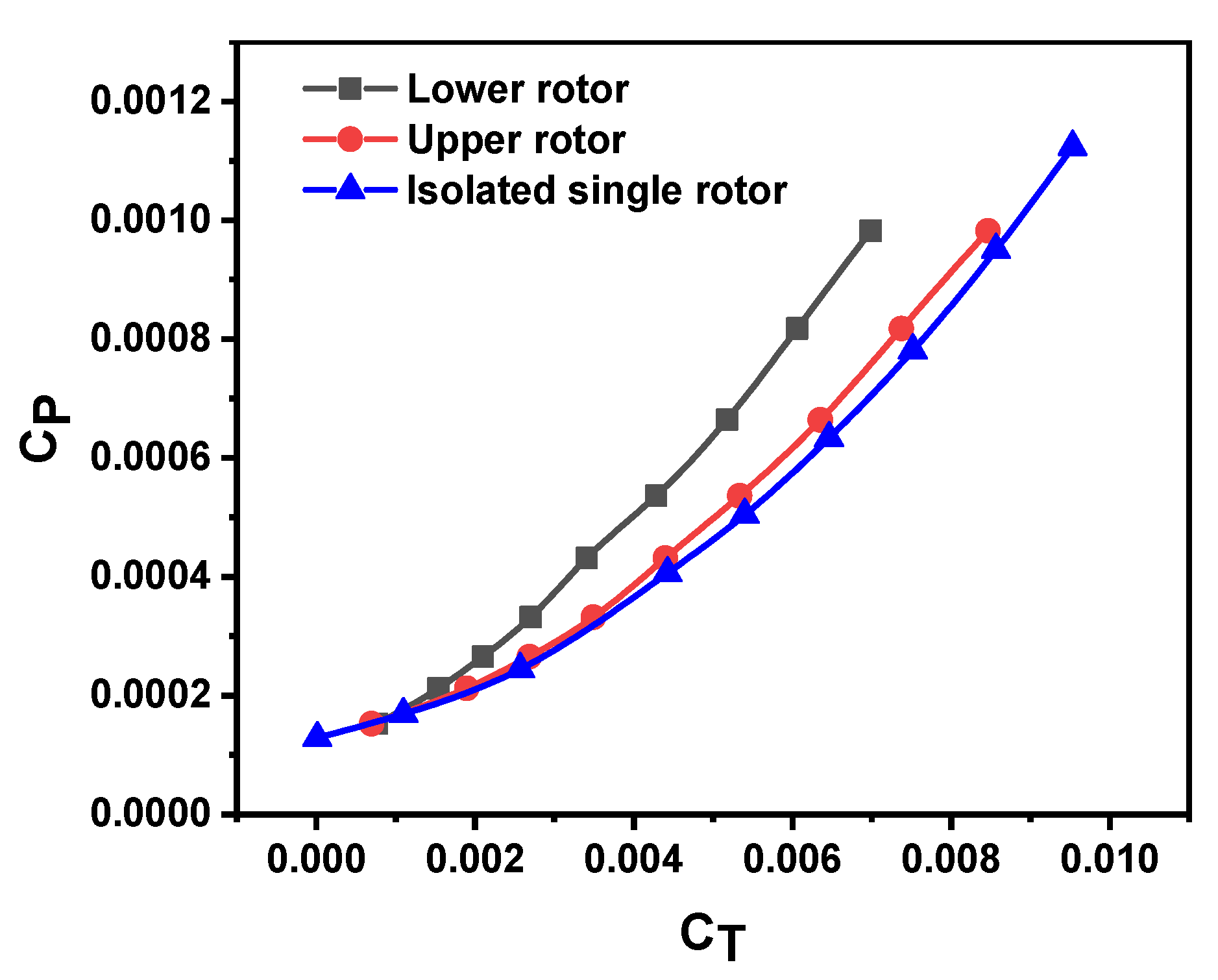
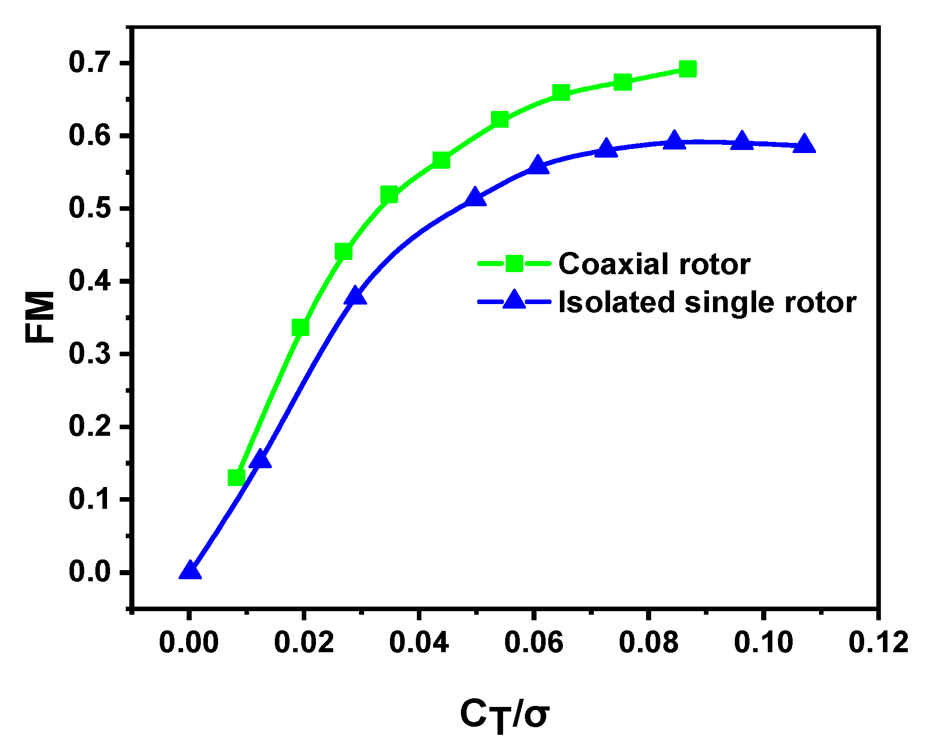
The hover test results demonstrate that the FM values of the upper and lower rotors are lower than that of the isolated single rotor and FM of the lower rotor is lower than that of the upper rotor. Moreover, the coaxial rotor configuration can contribute to better hover efficiency under the same blade loading condition.
(2)
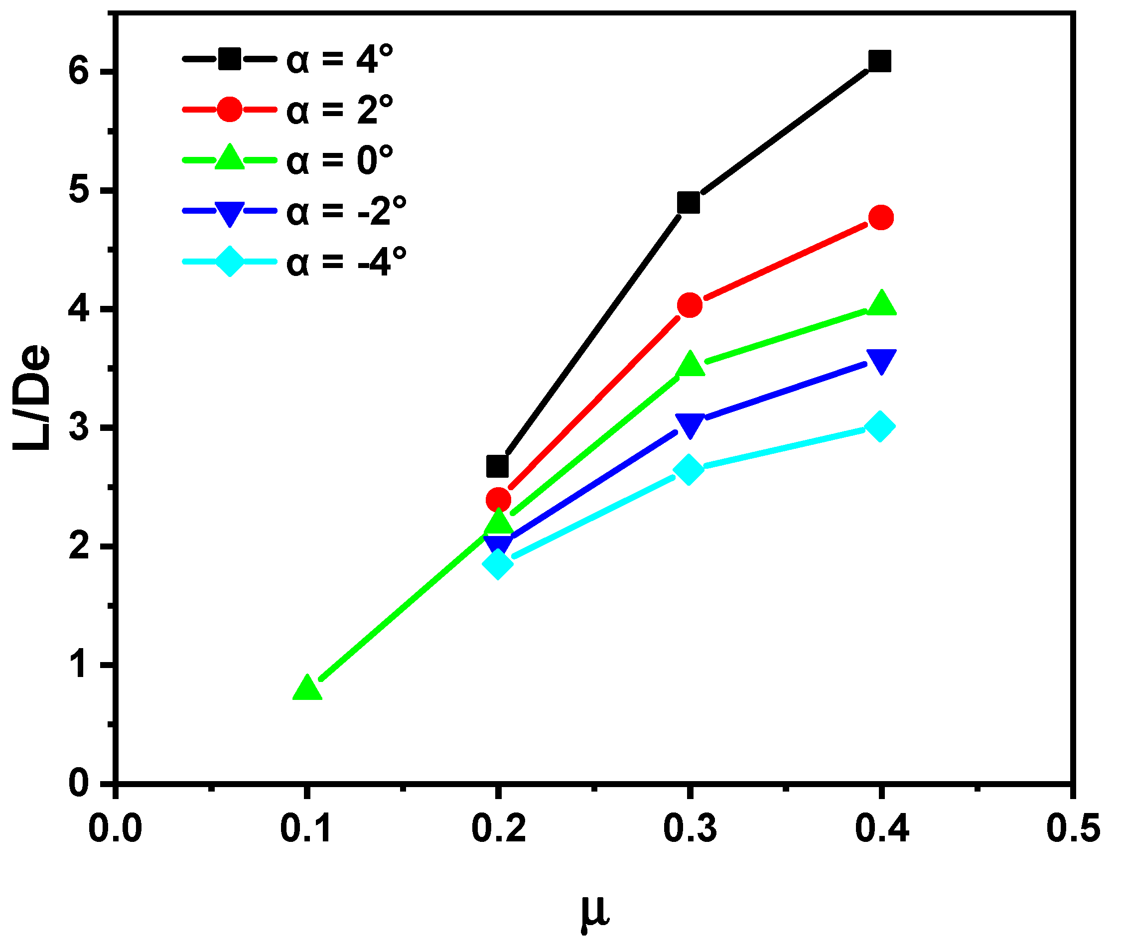
The effective L/De ratio of the coaxial rigid rotor does not monotonously increase as the advance ratio increases. The increases of the required power and drag in the case with a high advance ratio of 0.6 led to the decreasing L/De ratio of the rotor system with an advance ratio of above 0.4. Moreover, the L/De ratio of the rotor is relatively high when the rotor shaft is tilted backward.
(3)
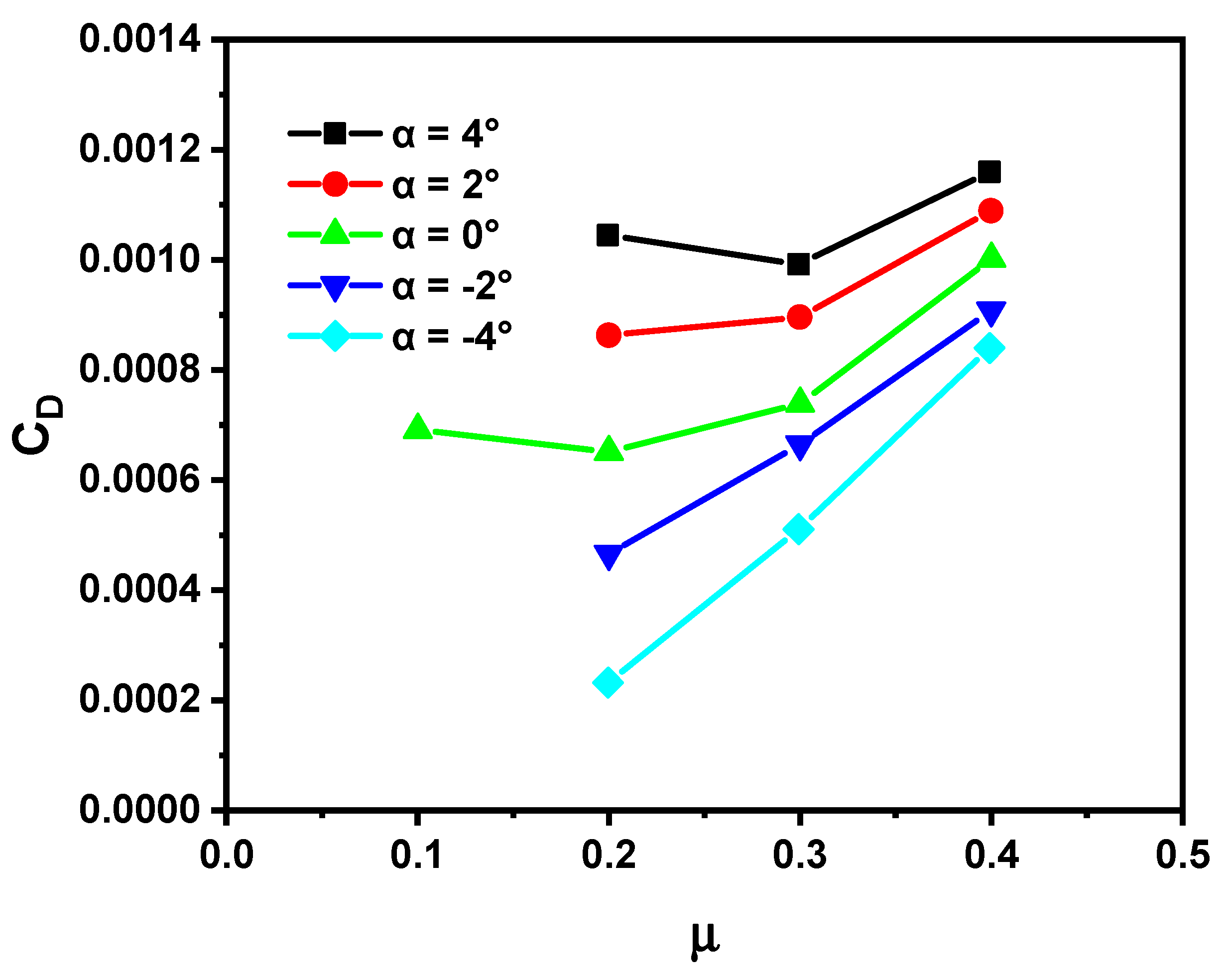
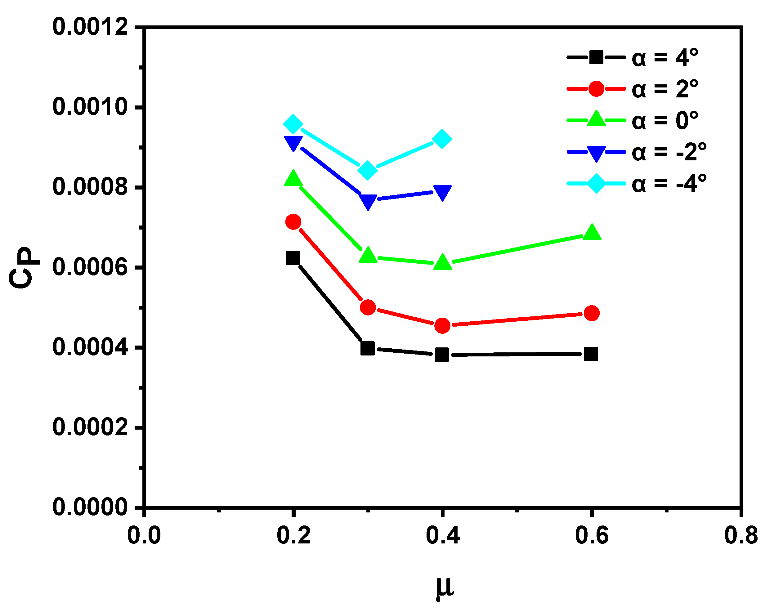
The increase in lift offset will reduce the total pitch whilst maintaining the same rotor lift, resulting in a decrease in the power required by the rotor. Moreover, the rotor drag is increased when there is an increase in the attack angle of the forward edge blade in the high dynamic pressure area of the advancing side. When the effect of the reduced rotor power is greater than that of the increased rotor drag, the L/De ratio increases as the lift offset increases. At a lower advance ratio, forward efficiency does not obviously benefit from the increasing lift offset and it even decreases when the lift offset becomes exceedingly high. At a higher advance ratio of 0.4, the benefit of the decreased rotor power is greater than the effect of the increased rotor drag, and the rotor obtains approximately 20% better overall forward efficiency with increased lift offset.
(4)
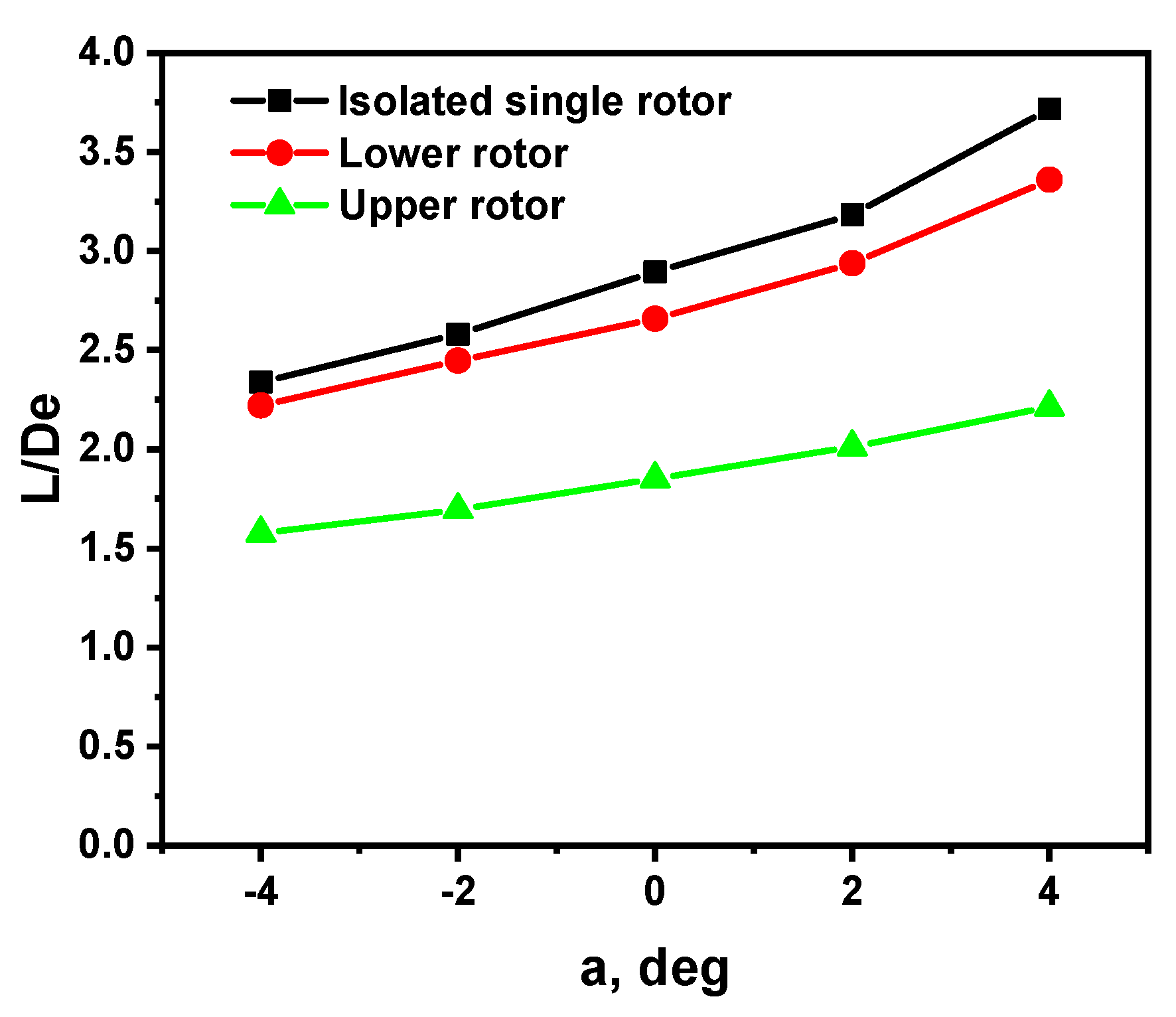
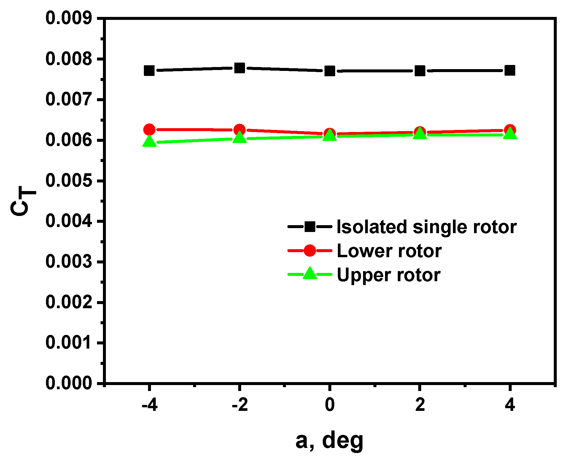
In the forward flight state, the L/De ratios of the upper and lower rotors are smaller than that of the isolated single rotor and that of the upper rotor is lower than that of the lower rotor. The difference in the forward state’s efficiency of upper and lower rotors is significantly different from the case in the hover flight state.

Author Contributions

Conceptualization, M.H. and H.W.; investigation and writing, C.W.; data acquisition and rotor control, X.P., G.Z. and M.T.; supervision, M.H.; project administration, M.H.; funding acquisition, M.H. All authors have read and agreed to the published version of the manuscript.

Funding

This research was funded by the National Natural Science Foundation of China (Grant No. 11672323).

Institutional Review Board Statement

Not applicable.

Informed Consent Statement

Not applicable.

Data Availability Statement

The data that support the findings of this study are available from the corresponding author upon reasonable request.

Acknowledgments

The rigid coaxial rotor model for this test was developed by China Helicopter Research & Development Institute. The authors also thank the staff of the Φ3.2 m Wind Tunnel for their valuable assistance with wind tunnel testing.

Conflicts of Interest

The authors declare no conflict of interest.

Nomenclature

TRotor thrust force, N
DRotor drag force, N
LRotor lift force, N
PRotor power, W
M x Rotor rolling moment, N·m
ρAir density, kg/m3
RRotor radius, m
αRotor shaft tilt angle, deg.
σRotor solidity
C T Rotor thrust coefficient
C P Rotor power coefficient
C L Rotor lift force coefficient
C D Rotor drag force coefficient
C Mx Rotor rolling moment coefficient
LOSLateral lift offset
L/DeEffective lift-to-drag ratio
FMFigure of merit
C T Blade loading coefficient
μAdvance ratio
ρAir density, kg/m3
ωRotor angular velocity, rad/s
ΨBlade azimuthal angle, deg.
θ up Blade pitch angle of upper rotor, deg.
θ lo Blade pitch angle of lower rotor, deg.
θ 0.7 Coupled collective pitch, deg.
A 1 Coupled longitudinal cyclic pitch, deg.
B 1 Coupled lateral cyclic pitch, deg.
θ 0.7 Differential collective pitch, deg.
A 1 Differential longitudinal cyclic pitch, deg.
B 1 Differential lateral cyclic pitch, deg.
θ 0.7 up Collective pitch of upper rotor, deg.
A 1 up Longitudinal cyclic pitch of upper rotor, deg.
B 1 up Lateral cyclic pitch of upper rotor, deg.
θ 0.7 lo Collective pitch of lower rotor, deg.
A 1 lo Longitudinal cyclic pitch of lower rotor, deg.
B 1 lo Lateral cyclic pitch of lower rotor, deg.
Γ Rotor phase lag angle, deg.
ΦDiameter
Subscripts
upUpper rotor
loLower rotor
hubRotor hub
Free-stream conditions

References

  1. Leishman, G.J. Principles of Helicopter Aerodynamics, 2nd ed.; Cambridge University Press: Cambridge, UK, 2016. [Google Scholar]
  2. Blackwell, R.; Millott, T. Dynamic Design Characteristics of the Sikorsky X2 TD Aircraft. In Proceedings of the American Helicopter Society 65th Annual Forum, Montréal, QC, Canada, 29 April–1 May 2008. [Google Scholar]
  3. Ruddell, A.J. Advancing Blade Concept (ABC) Development. J. Am. Helicopter Soc. 1976, 22, 13–23. [Google Scholar] [CrossRef]
  4. Cheney, M.C. The ABC Helicopter. J. Am. Helicopter Soc. 1969, 14, 10–19. [Google Scholar] [CrossRef]
  5. Paglino, V.M.; Beno, E.A. Full-Scale Wind-Tunnel Investigation of the Advancing Blade Concept Rotor System; United Technologies Corp, Sikorsky Aircraft Div: Stratford, CT, USA, 1971. [Google Scholar]
  6. Felker, F.F. Performance and Loads Data from a Wind Tunnel Test of a Full-Scale, Coaxial, Hingeless Rotor Helicopter; National Aeronuatics and Space Administration Ames Research Center: Moffett Field, CA, USA, 1981.
  7. Cameron, C.G.; Sirohi, J. Performance and Loads of a Lift Offset Rotor: Hover and Wind Tunnel Testing. J. Am. Helicopter Soc. 2019, 64, 1–12. [Google Scholar] [CrossRef]
  8. Cameron, C.; Sirohi, J. Performance and loads of a model coaxial rotor part II prediction validations with measurements. In Proceedings of the AHS 72nd Annual Forum, West Palm Beach, FL, USA, 17–19 May 2016. [Google Scholar]
  9. Cameron, C.G.; Uehara, D.; Sirohi, J. Transient Hub Loads and Blade Deformation of a Mach-Scale Coaxial Rotor in Hover. In Proceedings of 56th AIAA/ASCE/AHS/ASC Structures, Structural Dynamics, and Materials Conference, AIAA SciTech, Kissimmee, FL, USA, 5–9 January 2015. [Google Scholar]
  10. Lorber, F.P.; Law, G.K.; O’Neill, J.J.; Matalanis, C.; Bowles, P. Overview of S-97 RaiderTM Scale Model Tests. In Proceedings of the American Helicopter Society 72nd Annual Forum, West Palm Beach, FL, USA, 17–19 May 2016. [Google Scholar]
  11. Lorber, F.P.; Bowles, P.; Fox, E.; Wang, Z.K.; Hein, B.; Mayrides, B. Wind tunnel testing for the SB > 1 DEFIANT™ joint multi-role technology demonstrator. In Proceedings of the AHS International 73rd Annual Forum & Technology Display, Fort Worth, TX, USA, 9–11 May 2017. [Google Scholar]
  12. Ruddell, A.; Groth, W.; McCutcheon, R. Advancing Blade Concept (ABC) TM Technology Demonstrator; Technical Report USAVRADCOM-TR-81-D-5; U.S. ArmyResearch and Technology Labotratories (AVRADCOM): Maryland, MD, USA, 1981. [Google Scholar]
  13. Yeo, H.; Johnson, W. Investigation of Maximum Blade Loading Capability of Lift-Offset Rotors. J. Am. Helicopter Soc. 2014, 59, 1–12. [Google Scholar] [CrossRef]
  14. Bagai, A. Aerodynamic Design of the X2 Technology Demonstrator Main Rotor Blade. In Proceedings of the American Helicopter Society 64th Annual Forum, Alexandria, VA, USA, 29 April–1 May 2008. [Google Scholar]
  15. Leishman, J.G.; Ananthan, S. Aerodynamic optimization of a coaxial proprotor. In Proceedings of the 62th American Helicopter Society Annual Forum, American Helicopter Society, Phoenix, AZ, USA, 9–11 May 2006; Volume 1, p. 64. [Google Scholar]
  16. Rand, O.; Khromov, V. Aerodynamic optimization of coaxial rotor in hover and axial flight. In Proceedings of the 27th International Congress of the Aeronautical Sciences, Nice, France, 19–24 September 2010; pp. 1–13. [Google Scholar]
  17. Leishman, J.G.; Rosen, K.M. Challenges in the aerodynamic optimization of high-efficiency proprotors. J. Am. Helicopter Soc. 2011, 56, 12004. [Google Scholar] [CrossRef]
  18. Syal, M.; Leishman, J.G. Aerodynamic optimization study of a coaxial rotor in hovering flight. J. Am. Helicopter Soc. 2012, 57, 1–15. [Google Scholar] [CrossRef]
  19. Saetti, U.; Enciu, J.; Horn, J.F. Performance and design optimization of the f-helix evtol concept. In Proceedings of the Vertical Flight Society’s 75th Annual Forum and Technology Display, Philadelphia, PA, USA, 13–16 May 2019. [Google Scholar]
  20. Syal, M. Contributions to the Aerodynamic Optimization of a Coaxial Rotor System. Master’s Thesis, University of Maryland, College Park, MD, USA, 2008. [Google Scholar]
  21. Knight, M.; Hefner, R.A. Static Thrust Analysis of the Lifting Airscrew; NASA Technical Report NACA TN 626; NASA: Washington, DC, USA, 1937. Available online: https://ntrs.nasa.gov/citations/19930081433 (accessed on 25 July 2021).
  22. Berry, B.; Chopra, I. High-Advance Ratio Wind Tunnel Testing of a Model Rotor with Pressure Measurements. In Proceedings of the 5th Decennial AHS Aeromechanics Specialists’ Conference Proceedings, San Francisco, CA, USA, 22–24 January 2014. [Google Scholar]
  23. Wang, X.; Trollinger, L.; Chopra, I. Refined Performance Results on a Slowed Mach-Scaled Rotor at High Advance Ratios. J. Am. Helicopter Soc. 2020, 65, 1–13. [Google Scholar] [CrossRef]
  24. Wang, X.; Bauknecht, A.; Maurya, S.; Chopra, I. Slowed Hingeless Rotor Wind Tunnel Tests and Validation at High Advance Ratios. J. Aircr. 2021, 58, 153–166. [Google Scholar] [CrossRef]
Figure 1. The Φ2 m coaxial rigid rotor test rig.
Aerospace 08 00205 g001
Figure 2. Installation of the upper and lower rotors in the test rig.
Aerospace 08 00205 g002
Figure 3. Counter-rotating coaxial rotor system installed on the test rig in the wind tunnel test section.
Aerospace 08 00205 g003
Figure 4. Fan plot of the first modes.
Aerospace 08 00205 g004
Figure 5. Definition of the azimuthal rotor blade position. (a) Upper rotor; (b) lower rotor.
Aerospace 08 00205 g005
Figure 6. Relationships between power coefficient (CP) and thrust coefficient (CT) of upper, lower, and isolated single rotors.
Aerospace 08 00205 g006
Figure 7. Variations of figure of merit (FM) values for the coaxial and isolated single rotors with blade loading coefficient ( C T /σ).
Aerospace 08 00205 g007
Figure 8. Effective lift-to-drag (L/De) ratio as a function of the advance ratio (μ), 1860 rpm.
Aerospace 08 00205 g008
Figure 9. Power coefficient (CP) as a function of the advance ratio (μ), 1860 rpm.
Aerospace 08 00205 g009
Figure 10. Drag force coefficient (CD) as a function of the advance ratio (μ), 1860 rpm.
Aerospace 08 00205 g010
Figure 11. L/De ratio as a function of the advance ratio (μ), 1100 rpm.
Aerospace 08 00205 g011
Figure 12. Power coefficient (CP) as a function of the advance ratio (μ), 1100 rpm.
Aerospace 08 00205 g012
Figure 13. Drag force coefficient (CD) as a function of the advance ratio (μ), 1100 rpm.
Aerospace 08 00205 g013
Figure 14. Rolling moment coefficient ( C Mx ) of each rotor as a function of the lift offset (LOS).
Aerospace 08 00205 g014
Figure 15. Coupled collective pitch ( θ 0.7 ) as a function of the lift offset (LOS).
Aerospace 08 00205 g015
Figure 16. Lateral cyclic pitch of upper and lower rotors ( B 1 up and B 1 lo ) as a function of the lift offset (LOS).
Aerospace 08 00205 g016
Figure 17. Power coefficient (CP) as a function of the lift offset (LOS).
Aerospace 08 00205 g017
Figure 18. Drag force coefficient (CD) as a function of the lift offset (LOS).
Aerospace 08 00205 g018
Figure 19. L/De ratio as a function of the lift offset (LOS).
Aerospace 08 00205 g019
Figure 20. Variations of L/De ratio with rotor shaft tilt angles (a) for coaxial and isolated single rotors.
Aerospace 08 00205 g020
Figure 21. Variations of thrust coefficients (CT) with rotor shaft tilt angles (a) for coaxial and isolated single rotors.
Aerospace 08 00205 g021
Figure 22. Variations of power coefficients (CP) with rotor shaft tilt angles (a) for coaxial and isolated single rotors.
Aerospace 08 00205 g022
Table 1. Balance capacity and calibration accuracy.
Measurement ParametersMaximum CapacityMeasured Standard Deviation of Error
Value% Capacity
Normal force or lift, N22000.660.03
Side force, N5000.30.06
Axial force or drag, N5000.250.05
Pitching moment, N·m2000.080.04
Rolling moment, N·m2500.050.02
Torque, N·m3400.270.08
Table 2. Rotor parameters.
Rotor ParametersValue
Rotor radius, R (m)1
Root cut out (m)0.18
Number of blades8 (4 for the upper rotor and 4 for the lower rotor)
Chord (m)0.07
Twist angle (°)−12
Plan formUntapered
Precone angle (°)2
Rotational directionCounterclockwise for the upper rotor, clockwise for the lower rotor.
Solidity, σ0.178 (coaxial rotor)
AirfoilNACA0026, NACA0020, and NACA0012
Nominal rotation speed1860 RPM
Publisher’s Note: MDPI stays neutral with regard to jurisdictional claims in published maps and institutional affiliations.

