1. Introduction
The Space Solar Power Satellite (SSPS) was first invited by P. Glaser in 1968, the concept of which is that the sunlight is captured in space and converted into direct current, and then irradiated to the ground receivers on the earth [
1]. For the restrictions of day and night and climate, the average power density of the ground-based solar energy is limited to about 300~400 W/m
2, while the value of the space-based solar energy is stabilized at 1367 W/m
2 [
2]. Therefore, the SSPS is regarded as a promising methodology to provide the earth with a clean baseload and great efforts have been paid by scientists around the world since the invention of the concept.
P. Glaser raised the original SSPS in 1968, a gigantic spherical solar array with a diameter of 10 km collects incident sunlight [
1]. In the 1970s, NASA conducted SSPS studies and proposed the Reference Model [
3]. The model captures the sunrays with a huge flat solar array about 50 km
2 in area but finally canceled due to excessive investment and low-mature technologies. From 1995 to 2001, NASA implemented the Fresh Look Study and the SERT Program. Several SSPS models were put forward, such as Sun Tower with power generation via identical units for Solar Power Generation (SPG) module, Solar Disc with scalable photovoltaic (PV) segments, Integrated Symmetrical Concentrator (ISC) with one group of huge parabolic concentrators, and Symmetrical Two-stage Flat Reflected Concentrator (SFTC) which has the advantage to obtain suitable energy distribution by adjusting the primary and secondary reflectors [
4]. JAXA and USEF made some significant technical progress toward the realization of SSPS. Several models, for instance, Tethered-SSPS and 2001–2003 JAXA Models were proposed to cope with economic and technological challenges [
5]. In 2012, John C. Mankins proposed the Arbitrarily Large Phased Array (ALPHA) concept [
6]. Hyper-modular design, distributed focus, thin-film reflector, retrodirective phase-controlled Wireless Power Transmission (WPT) were all introduced to decrease the difficulty on construction whilst increasing the system performance.
Although great efforts have been implemented on the conceptual design of the SSPS, large scale, large fluctuation on solar energy gathering, difficult control strategies, low collection efficiency, and other factors resist the previous conceptual models being realized [
7]. For instance, Sun Tower transfers the direct current with the central power management and distribution cables at the length of 10 km, and the tower can hardly supply energy near 00:00 a.m. and 12:00 p.m. due to the self-shadowing of the concentrated photovoltaic cell modules [
8]. Tethered-SSPS could not capture sunrays near 6 a.m. and 6 p.m. because the sandwich structure could not track the sunlight. Complicated strategies and thermal problems on the sandwich structure are great challenges to the STFC [
9,
10]. Light leaking and independent adjustment for thousands of thin-film reflectors resist the performance of the ALPHA [
7,
11].
Table 1 summarizes some typical SSPS conceptual designs.
Concerning the previous factors, the authors propose a novel SSPS model, which is expected to increase the system efficiency and energy distribution uniformity, and decrease the challenges on thermal management and solar tracking. Firstly, the line-focused mode is analyzed and a circular trough concentrator based on the mode is introduced to decrease the sunlight collection fluctuation in a natural day. Secondly, the optical performance of the concentrator is evaluated with ray-trace technique. Thirdly, the geometry on the PV cell array is optimized to improve the distribution uniformity and decrease the area of the cell array. A numerical example verifies its validity. Then, modular design is conducted on the ideal circular trough concentrator and its influence on the optical performance is discussed. Finally, the primary structure of the novel SSPS is designed with the previous modular concentrator and optimized cell array.
2. Line-Focused Mode
In this section, the principle of optics for the line-focused mode is analyzed, and an ideal circular trough concentrator based on the focus mode is evaluated.
2.1. Principle of Optics
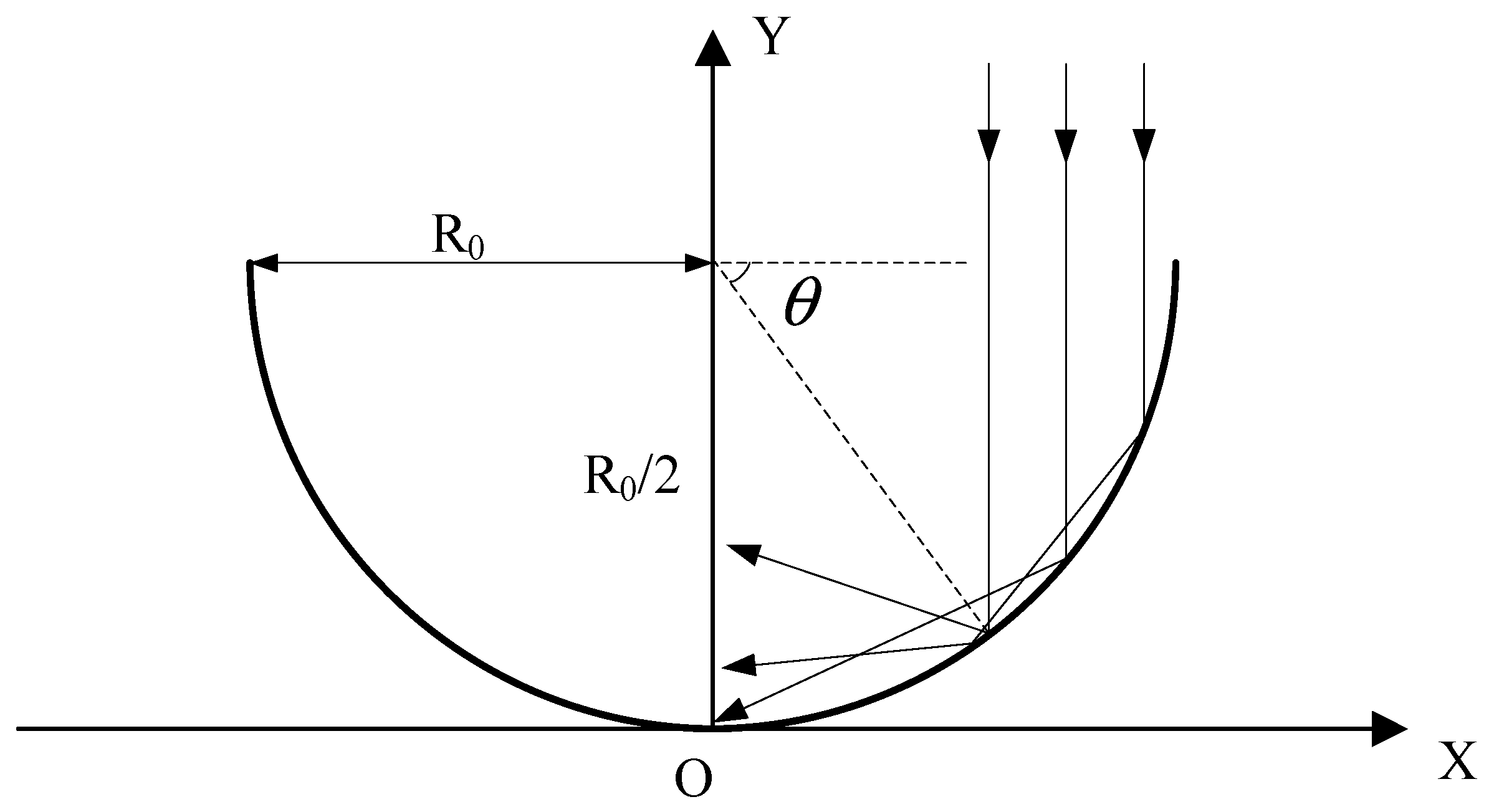
Shown in
Figure 1, the description of the generatrix geometry of a circular trough concentrator can be given by:
where
is the radius of the concentrator, measured in meters and calculated as:
where
is the solar power irradiating the PV cell array,
is the solar constant in space at a value of 1367 W/m
2,
represents the reflectance of the concentrator,
is the collection efficiency of the concentrator.
is the length of the concentrator, measured in meters.
The sunrays paralleling to the
Y-axis are reflected by the reflector, the reflected rays can be calculated as:
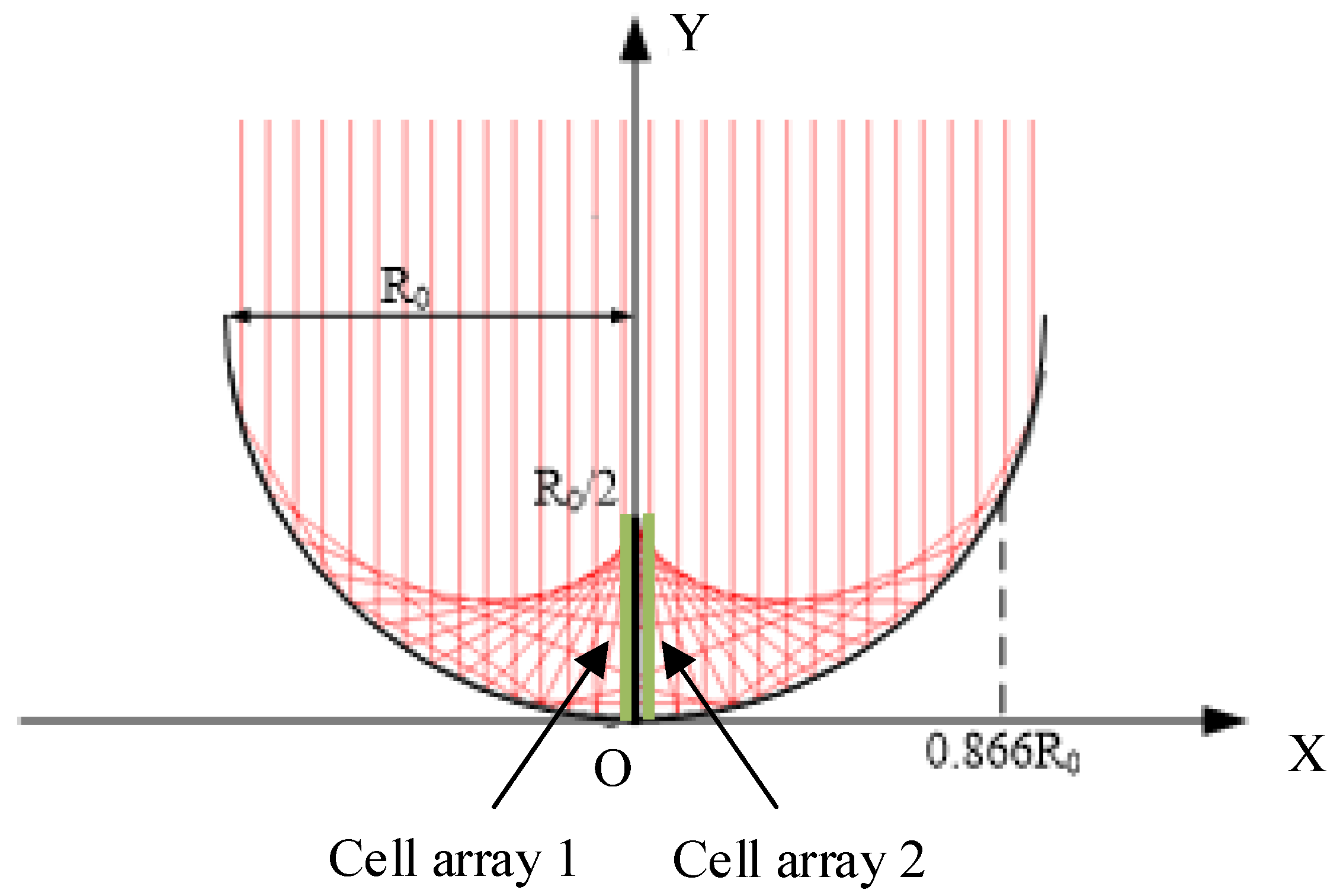
With Equations (1) and (3), the incident sunrays and reflected sunrays can be shown in
Figure 2.
As is shown in
Figure 2, the reflected rays can be described as envelopes. By solving Equation (3), the ordinate of the intersection of the reflected rays and the
Y-axis varies from 0 to
, the focus mode of which can be expressed as line-focused mode [
12].
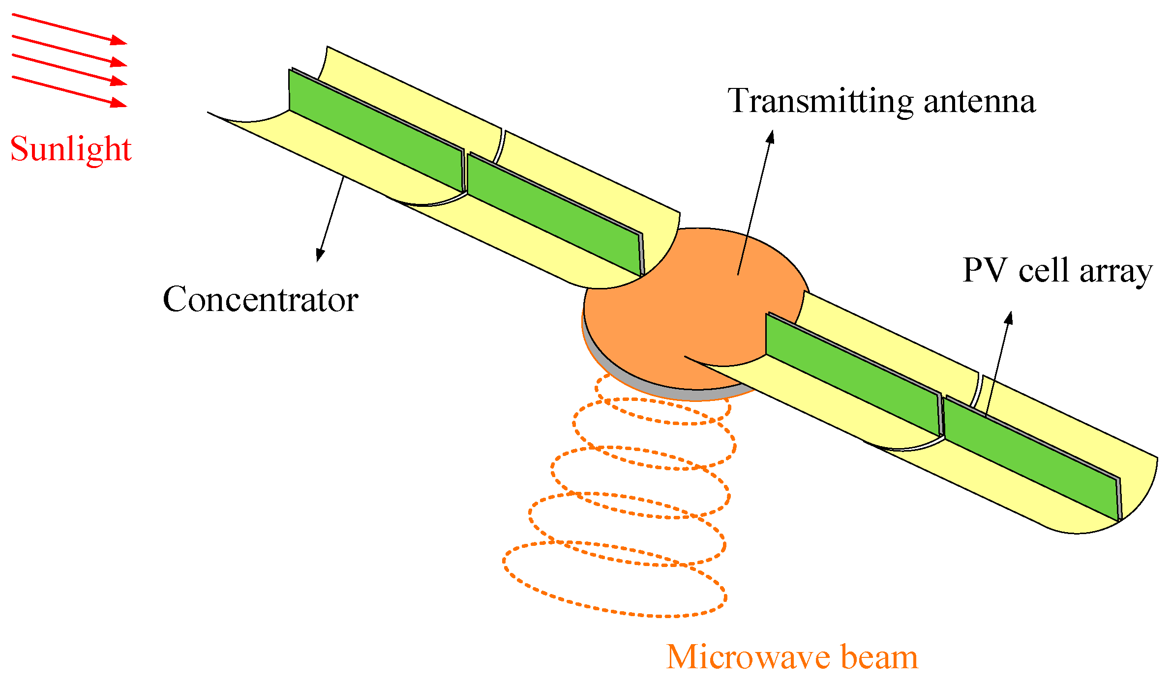
For the same curvature radius of any point in the generatrix circle, the collection efficiency of the concentrator would be basically maintained in a natural day. Therefore, the authors utilize circular trough concentrator and line-focused mode to theoretically ensure the energy collection stability. To satisfy scalable segment and avoid a single point of failure by an ultra-large reflector, an original SSPS model based on the line-focused mode is proposed, which is composed of a high-power microwave transmitting antenna, scalable solar energy collection and conversion system (circular trough solar concentrator and PV cell array), and power management and distribution (PMAD) system. A detailed description of the PMAD is presented in
Section 5). The height of the cell array is equal to half of the radius of the reflector modules. The diagram of the original line-focused SSPS model is shown in
Figure 3.
For the PV cell array, concentrating technology is used to decrease the area of the cell and its cost while increasing the photoelectric conversion efficiency. High power concentration can greatly reduce the area of photovoltaic cells. However, on the one hand, the cost of high concentrating photovoltaics (HCPV) in space is excessive, on the other hand, the use of the HCPV relies on good heat dissipation conditions. Due to its high quality and cost, the cooling system is not suitable to be widely used in the SSPS system. For the SSPS, low concentrating photovoltaics (LCPV) would be utilized. The heat dissipation for the LCPV mainly depends on space autonomous radiation. For the original SSPS model, the cell array is two separated flat panels installed with LCPV modules covering the focus region from 0 to
, as is shown in
Figure 2.
2.2. Ray Tracing Analysis
The ray-trace method is used to analyze the optical performance of the original solar concentrator [
13,
14,
15]. For solar energy collection with SSPS in space, the normalized collection efficiency considering the sun’s non-parallelism is decreased by less than 0.4 percent to the case of parallelism [
12]. Therefore, all the incident sunrays are assumed to be parallel in space in this part of the work.
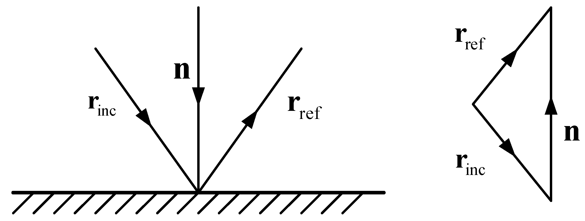
Figure 4 indicates the relationship between the direction vector of the incident ray, its reflected ray, and the normal vector of the reflector surface. The reflection law can be described as the following equation:
where
,
and
are the unit direction vector of an incident ray, the unit direction vector of its reflected ray, and the unit normal vector of the reflector surface.
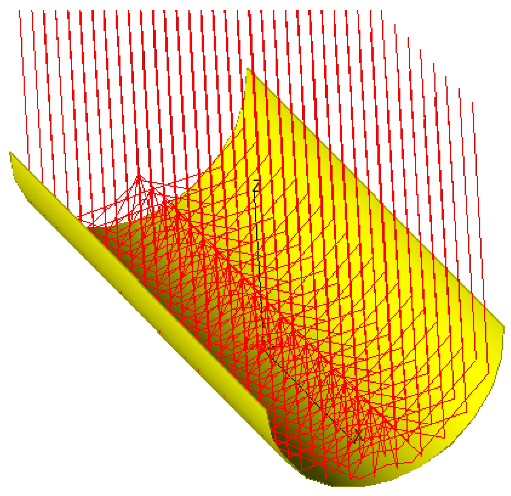
An example of the ray-trace technique is presented in
Figure 5. On the basis of optical law and the geometric description of the concentrator, all the incident rays are reflected and converged to the region from 0 to
along the
Y-axis. While
, the incident rays are reflected by two or more times to reach the focus region. The boundary between the one-time reflected region and multiple times reflected region is
, as is shown in
Figure 2. For the practical reflectivity and surface precision of the reflector modules, only the one-time reflection region is dealt with in this work.
Dividing the cell array into several statistical segments, the power density of each subsection can be calculated as:
where
is the area of the
subsection,
is the number of sunrays reflected to each subsection,
is the number of subsections, and
is the power of a single sunray, defined as:
where
represents the area of sunlight irradiating to the aperture of the concentrator,
is the number of the sampling sunrays.
Then, the optical concentration ratio
and collection efficiency
can be calculated as follows:
The standard deviation
is defined to evaluate the energy distribution uniformity, calculated as:
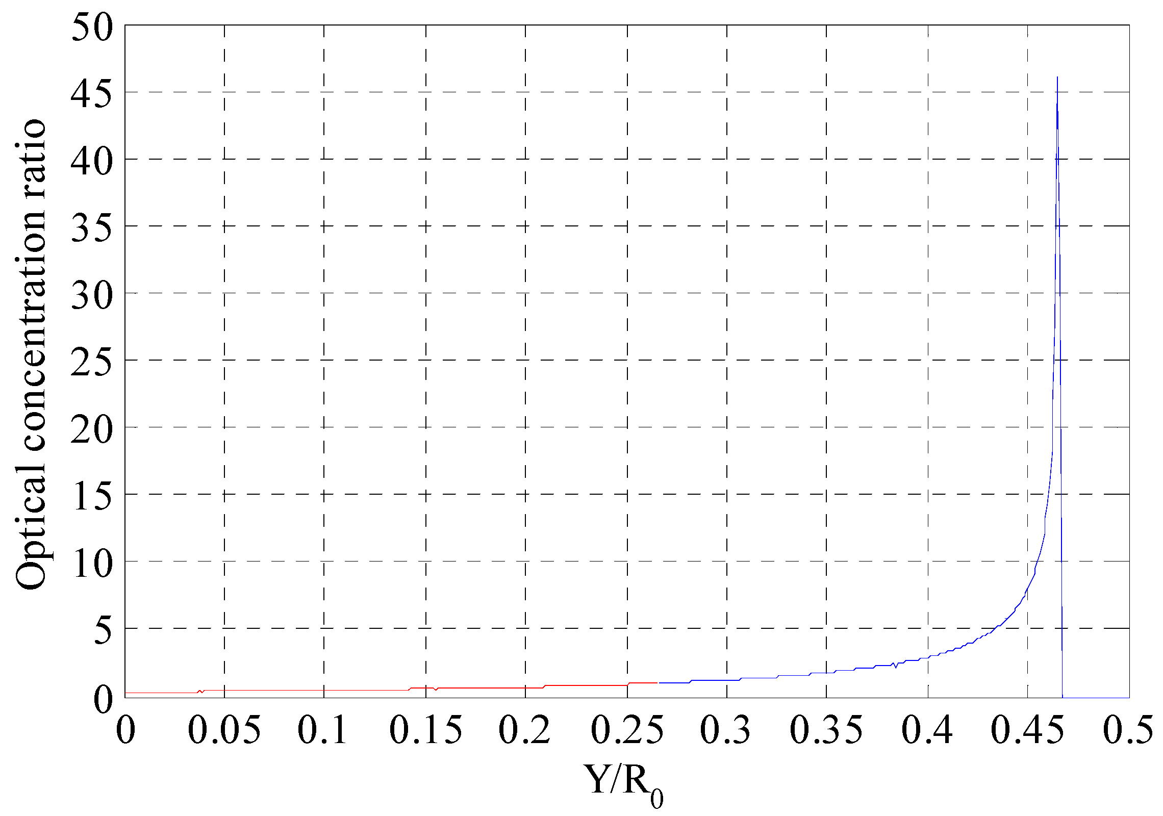
To precisely track the incident sunrays, the reflectance of the concentrator is assumed to be 100%. The statistical segment is set to 512. The distribution of the optical concentration ratio is shown in
Figure 6 whilst the optical parameters being presented in
Table 2.
As can be seen in
Figure 6 and
Table 2, the average concentration ratio is 1.743, the deviation is 3.529, and the ratio between the maximum value to the minimum value is as high as 153.663.
On the one hand, the nonuniform distribution would result in a decrease of photoelectric conversion efficiency and an increase of difficulty on the design of the back-end circuit system. As is stated in
Section 2.1, the SSPS is expected to use the concentrating technique to decrease the area of the cell array. However, the area in which the concentration ratio is less than 1.0 accounts for 52.930% of the total area of the original cell array, which has no benefit on the application of concentrating technology.
On the other hand, there exists high energy distribution region and the maximum concentration ratio is as high as 46.099. To utilize space autonomous radiation and avoid extensive use of active cooling system, LCPV should be implemented on the cell array. The thermal balance equation of the cell can be presented as:
where
and
represent the absorptivity and the emissivity of the PV cell, respectively.
is the photoelectric efficiency,
is the Stefan–Boltzmann constant.
and
are the temperature of the cell and the space environment (in degrees-Kelvin), respectively.
Based on Equation (10), the maximum concentration ratio is not expected to larger than 10.0. The maximum ratio in
Table 2 is far more than the acceptable concentration ratio that space photovoltaic cells can effectively work without a cooling system.
3. Optimization Design on the Geometry of the Cell Array
To improve the optical performances illustrated in
Section 2.2, the authors establish an optimization model to optimize the geometry of the cell array to change the energy distribution.
Invented in 1962, the Bézier curve is continuous and differentiable, which can be defined by a set of control points
through
, where
is the order of the Bézier curve. The first and last control points are always the end points of the curve. By virtue of the previous properties, the Bézier curve is used to describe the generatrix geometry of the cell array in an arbitrary shape. For the original flat plane cell array, the control points are in a straight line. Given the control points
, a Bézier curve is defined as:
where
is a Bernstein polynomial, described as:
By adjusting the coordinates of the control points, the optical performance of the cell array could be improved. Therefore, an optimization model is proposed as follows:
where the design variables
represent the coordinates of control points of a Bézier curve,
is the collection efficiency of the concentrator, calculated as Equation (8).
represents the upper limit on the distribution uniformity of the optical concentration ratio.
and
are the limits on the optical concentration ratio.
is the feasible region of the coordinates of the control points, all the control points should be within the envelopes, as is indicated in
Section 2.1.
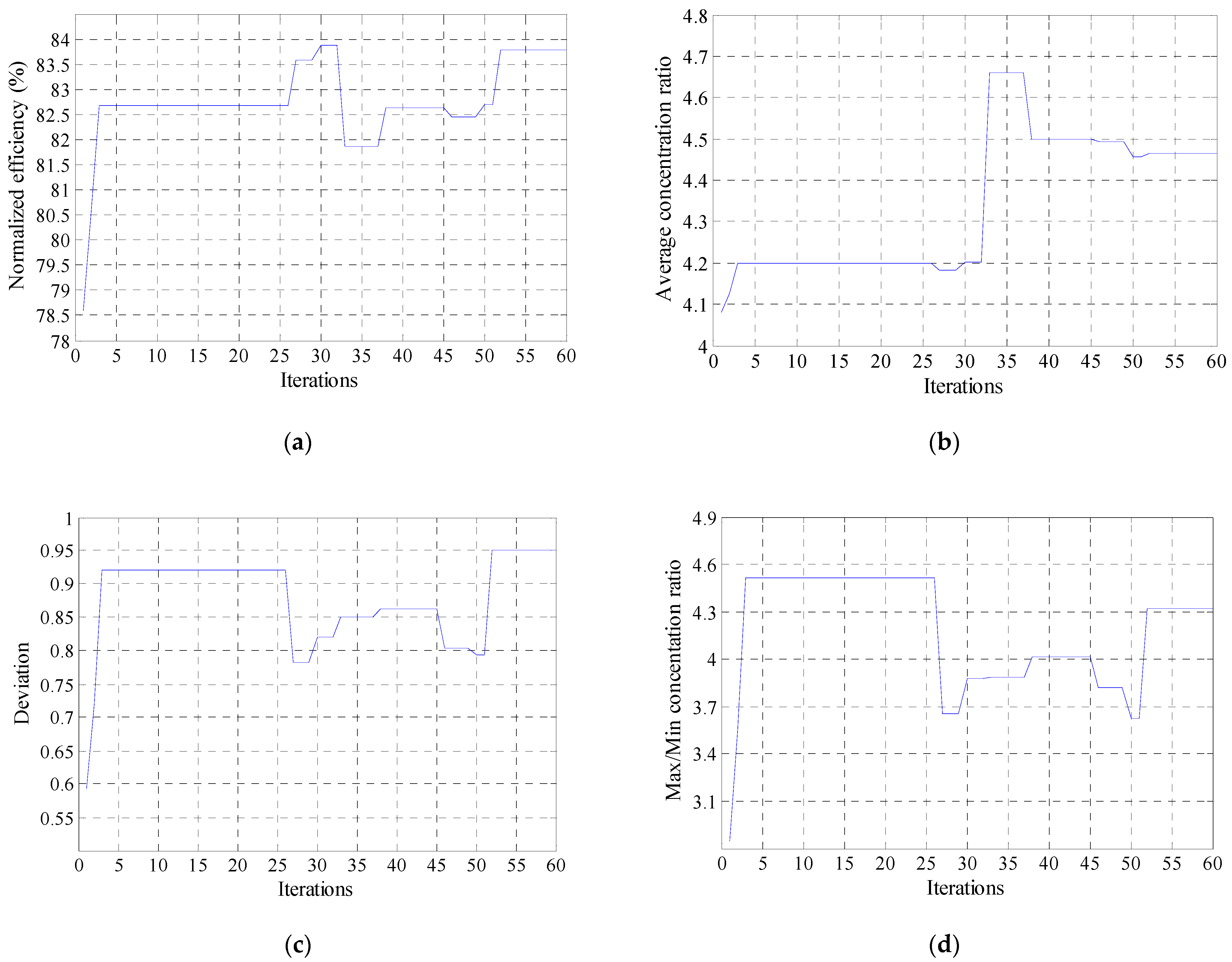
To test the proposed optimization model, the authors utilize a 2-order Bézier curve in the simulation process. The Particle Swarm Optimization (PSO) algorithm has become one of the most commonly used heuristic optimization methods, which has the characteristics of a simple algorithm, fewer computational resources, and high convergence speed. Therefore, the PSO algorithm is utilized to obtain the optimal results. Comprehensively considering calculation time and accuracy, the generation number is 60 and the population size is 30. The inertia weight decreases linearly from 0.9 to 0.4, and two acceleration constants are set to 2.0. During the simulation, the
is set to 1.0. As is indicated in
Section 2.2, the
and
are equal to 2.0 and 10.0, which are suitable for the LCPV technique. The variation of optical parameters with iterations is shown in
Figure 7. The coordinates of the control points and the distribution of concentration ratio are presented in
Figure 8 and
Table 3.
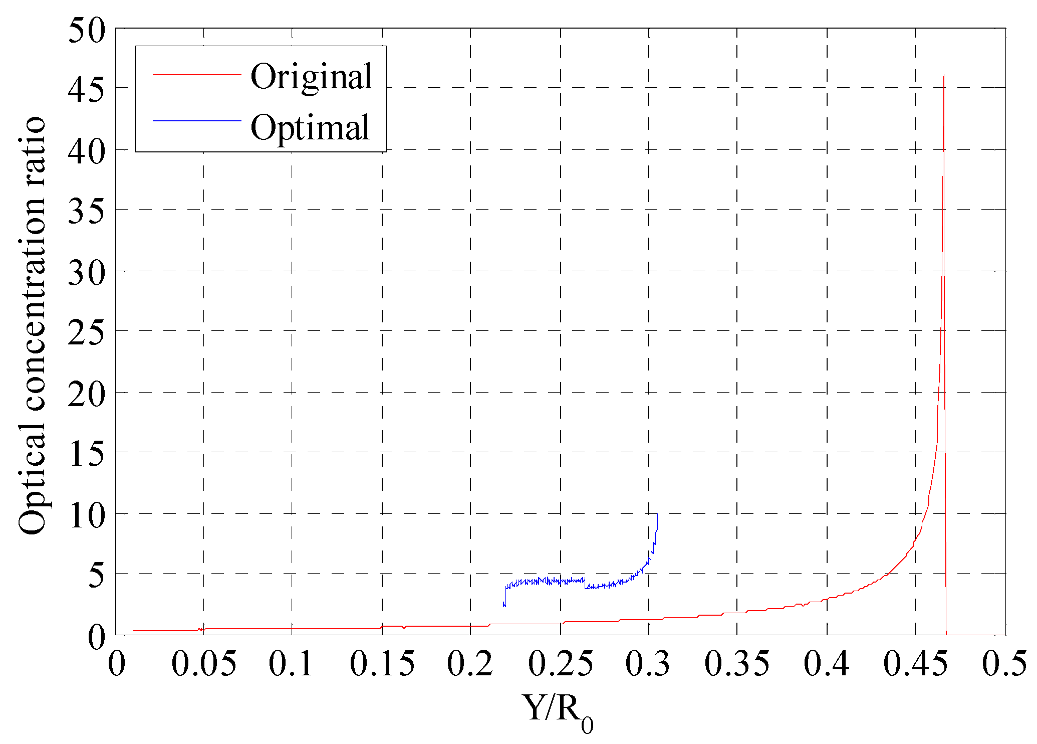
As is seen in
Figure 7 and
Figure 8, and
Table 3, the optical performance has been improved by the optimization design contrasted to the original flat plane cell array. The maximum optical concentration ratio is 9.826 while the minimum value is 2.220, and the ratio between these two values is controlled within 4.43. The average concentration ratio is about 4.463. Both the average value, the maximum and the minimum values are available for the LCPV technique. Besides, the deviation is decreased to 0.950, and the uniform power distribution benefits the design of the back-end circuit system. The normalized collection efficiency is about 83.77%. Furthermore, the area of the cell array in the original configuration is about
R0L while the area of the optimal cell array is about 0.302
R0L. The area is decreased by near 70%, which is conducive for the cost reduction.
4. Modular Design on the Circular Trough Concentrator
For the commercial SSPS, the output power is promising for MW or GW level and the scale is in the hundreds or thousands of meters [
16]. For example, the diameter of the transmitting antenna of the ALPHA is about 1.2 km and the diameter of the concentrator is larger than 3 km [
6]. In this section, modular design is introduced to deal with the construction of this ultra-large space structure. The authors propose a modular design method with planar modules and a simple control strategy for solar tracking to cope with the challenge of manufacture and control.
As mentioned, it is impracticable to construct the SSPS by integrated processing. The authors divide the ideal trough circular surface into several same flat planes. As shown in
Figure 9, the concentrator is constructed with supporting structure and thin-film planar reflector modules. The reflector module is consists of a supporting rod, high reflectivity thin film, connecting cables, and rotating devices. For one group of circular trough concentrators, the number of planar reflector modules is
N.
As is shown in
Figure 9c, coordinates of the vertex on the regular polygon can be calculated with:
The approximation error can be expressed as:
For commercial SSPS, the operating orbit is usually selected in the geostationary (GEO) orbit [
17]. While operating in the GEO orbit, the transmitting antenna remains relatively static to the earth and the relative position between the sunlight and concentrator varies periodically. One of the key techniques of the SSPS is solar tracking. For the Reference Model, the ISC, and the ALPHA, solar tracking is a great consumable process with difficult control strategies. The cell array of the Reference Model about 50 km
2 in area should be overall rotated to track the sun. Two groups of primary concentrators in a diameter of 3.5 km should be overall adjusted. As much as 4662 reflector modules should be adjusted independently for the ALPHA to gather sunlight.
Through the modular design, the overall adjustment would be replaced by the individual adjustment with simple control strategies. As is shown in
Figure 10, the planar reflector modules facing the sunlight direction are rotated to maintain their individual normal vector being perpendicular to the direction vector of the sunlight whilst the other modules keep their inner normal vectors directing to the geometry center of the concentrator. At any time, there are
N/2 modules capturing the sunlight and the others reflecting the sunlight to the optimal PV cell array designed in
Section 3.
Obviously, with the number of splicing modules increasing, the modular concentrator is closer to the ideal circular trough concentrator. Therefore, the influence of the collection efficiency caused by the different number of reflector modules should be evaluated. The authors obtain the relationship between the collection efficiency and the different number of modules. The results are presented in
Figure 11 and
Table 4.
As is indicated in
Figure 11 and
Table 4, the collection efficiency is increased with the increasing number of splicing reflector modules. While the concentrator consists of 200 planar modules, the collection efficiency is up to 78.31% while the value of the ideal circular trough concentrator is 83.77%. The efficiency loss caused by the splicing modules would be controlled with 5.5%.
5. Optimal Line-Focused SSPS Model
Based on the previous optical optimization and modular design, an optimal SSPS model is proposed. The primary structure is shown in
Figure 12.
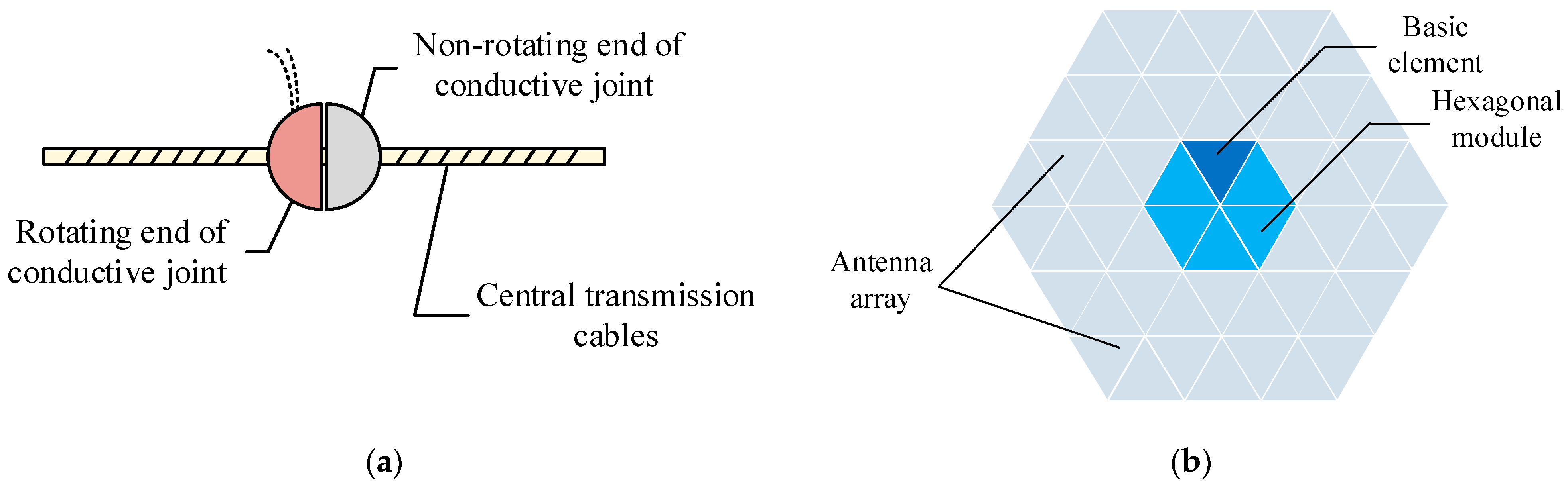
The optimal scheme is composed of a primary supporting structure, thin-film reflector modules, PV cell array, power management and distribution system, and high-power transmitting antenna. The reflector modules converge the incident sunrays to the PV cell array and then convert the sunlight into direct current. Then, the current is collected by the power management and distribution system and conveyed to the high-power transmitting antenna. Finally, the direct current is converted to high-power radio frequency and irradiated to the earth by the transmitting antenna.
The power management and distribution system consists of a rotating end of the conductive joint [
18], non-rotating end of the conductive joint, and central transmission cables, as is shown in
Figure 13a.
As is shown in
Figure 13b, the transmitting antenna is composed of a multi-layer construction strategy. Six groups of triangle elements constitute a hexagonal module. Several groups of modules form a sub-array. Finally, multiple sub-arrays compose into the antenna array.
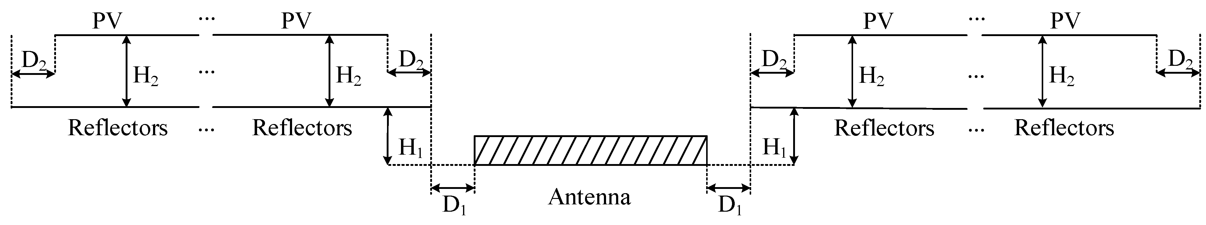
The scale of SSPS is huge, which results in difficulty and huge energy consumption on overall manufacturing. With the modular design, the number of the thin-film reflectors and the PV cell array is configurated with the demand of the power to the earth. Concerning the shadow problem on the PV cell array caused by the transmitting antenna and the obliquity of the ecliptic, the boundary dimensions of the PV cell array, reflector modules, and transmitting antenna can be described in
Figure 14 and as Equation (15):
where
,
and
are the height of reflectors, the height of PV cell array and the obliquity of the ecliptic, respectively.
is equal to
and
is determined by the control points of the Bézier curve obtained in
Section 3.
6. Conclusions
Based on the line-focused mode, this paper proposes a novel SSPS model consisting of a primary supporting structure, modular thin-film reflectors, PV cell array, power management and distribution system, and high-power transmitting antenna. The optical principle is analyzed, and optical optimization and modular design are conducted and discussed in detail.
(1) The novel SSPS mode is composed of a primary supporting structure, modular thin-film concentrator, PV cell array, power management and distribution system, and high-power microwave antenna. The novel model is modular and the number of modules of different parts can be decided by the output power to the earth and the system efficiency. Furthermore, the novel SSPS has a simple control strategy.
(2) The cell array has suitable power distribution with geometry optimization. The maximum optical concentration ratio is 9.826 while the minimum value is 2.220, available for LCPV technique and heat radiation without active cooling system. The energy distribution is uniform at a deviation of 0.950, which benefits the design of the back-end circuit system. The normalized collection efficiency is 83.77% and the area of the cell array is decreased by near 70% to the original flat planar cell array.
(3) Modular design is introduced to deal with the construction of this ultra-large concentrator and a simple control strategy is proposed to the modular thin-film concentrator modules for tracking the sunlight. With the modular design, the large circular trough concentrator is jointed with several identical planar modules. The efficiency loss caused by the splicing concentrator would be controlled with 5.5% when the number of modules is larger than 200.
(4) For future studies, the reflectance of the thin-film reflectors should be taken into consideration. The evaluation of PV power generation should be implemented. Besides, the influence caused by structural deformation should be evaluated and structural optimization to further improve structural and optical performance should be conducted.
Author Contributions
Conceptualization, Y.Y.; methodology, Y.Y.; software, Y.Y. and G.F.; validation, Y.Y., X.J.; writing—original draft preparation, Y.Y., and M.P.; writing—review and editing, Y.Y. and M.P.; project administration, Y.Y. All authors have read and agreed to the published version of the manuscript.
Funding
This research was funded by the Natural Science Foundation of Shaanxi Province (2020JQ-595) and the Natural Science Foundation of Shaanxi Provincial Department of Education (19JK0848).
Institutional Review Board Statement
Not applicable.
Informed Consent Statement
Not applicable.
Data Availability Statement
Data available on request due to restrictions eg privacy or ethical.
Conflicts of Interest
The authors declare no conflict of interest.
References
- Glaser, P.E. Power from the sun: Its future. Science 1968, 162, 857–861. [Google Scholar] [CrossRef] [PubMed]
- Committee for the Assessment of NASA’s Space Solar Power Investment Strategy; Aeronautics and Space Engineering Board; National Research Council. Laying the Foundation for Space Solar Power: An Assessment of NASA’s Space Solar Power; National Academy Press: Washington, DC, USA, 2001; pp. 8–11. [Google Scholar]
- Mankins, J.C. New directions for space solar power. Acta Astronaut. 2009, 65, 146–156. [Google Scholar] [CrossRef]
- URSI Inter-Commission Working Group on SPS. URSI White Paper on Solar Power Satellite (SPS) Systems and Report of the URSI Inter-Commission Working Group on SPS; URSI: Brussels, Belgium, 2007; pp. 92–110. [Google Scholar]
- Sasaki, S.; Tanaka, K.; Higuchi, K.; Okuizumi, N.; Kawasaki, S.; Shinohara, N.; Senda, K.; Ishimura, K. A new concept of solar power satellite: Tethered-SPS. Acta Astronaut. 2006, 60, 153–165. [Google Scholar] [CrossRef]
- Mankins, J.C. The Case for Space Solar Power; Virginia Edition Publishing: Houston, TX, USA, 2014; pp. 19–21. [Google Scholar]
- Yang, Y.; Zhang, Y.; Duan, B.; Wang, D.; Li, X. A novel design project for space solar power station (SSPS-OMEGA). Acta Astronaut. 2016, 121, 51–58. [Google Scholar] [CrossRef]
- Mankins, J.C. A technical overview of the ‘Sun Tower’ solar power satellite concept. Acta Astronaut. 2002, 50, 369–377. [Google Scholar] [CrossRef]
- Meng, X.-L.; Xia, X.-L.; Sun, C.; Hou, X.-B. Adjustment, error analysis and modular strategy for Space Solar Power Station. Energy Convers. Manag. 2014, 85, 292–301. [Google Scholar] [CrossRef]
- Jaffe, P.; Hodkin, J.; Harrington, P. Sandwich module prototype progress for space solar power. Acta Astronaut. 2014, 94, 662–671. [Google Scholar] [CrossRef]
- Renzi, M.; Bartolini, C.M.; Santolini, M.; Arteconi, A. Efficiency assessment for a small heliostat solar concentration plant. Int. J. Energy Res. 2015, 39, 265–278. [Google Scholar] [CrossRef]
- Yang, Y.; Zhang, Y.Q.; Fan, G.H.; Li, M.; Pei, M. Construction strategy and performance analysis of large-scale spherical solar concentrator for the Space Solar Power Station. Sol. Energy 2020, 207, 133–143. [Google Scholar] [CrossRef]
- Ali, I.M.S.; O’Donovan, T.S.; Reddy, K.; Mallick, T.K. An optical analysis of a static 3-D solar concentrator. Sol. Energy 2013, 88, 51–58. [Google Scholar]
- Sellami, N.; Mallick, T.K. Optical efficiency study of PV crossed compound parabolic concentrator. Appl. Energy 2013, 102, 868–876. [Google Scholar] [CrossRef]
- Goswami, D.Y. Principles of Solar Engineering, 3rd ed.; CRC Press: New York, NY, USA, 2015; pp. 127–129. [Google Scholar]
- Fan, G.; Zhang, Y.; Ji, X.; Li, X.; Yang, Y. Optical-structural integrated optimization design of deployable beams in OMEGA Space Solar Power Satellite. J. Aerosp. Eng. 2019, 32, 04019097. [Google Scholar] [CrossRef]
- Wie, B.; Roithmayr, C.M. Attitude and orbit control of a very large geostationary solar power satellite. J. Guid. Control Dyn. 2005, 3, 439–451. [Google Scholar] [CrossRef]
- Hou, X.B.; Wang, L.; Zhang, X.H.; Zhou, L. Concept design on multi-rotary joints SPS. J. Astronaut. 2015, 11, 1332–1338. [Google Scholar]
| Publisher’s Note: MDPI stays neutral with regard to jurisdictional claims in published maps and institutional affiliations. |
© 2021 by the authors. Licensee MDPI, Basel, Switzerland. This article is an open access article distributed under the terms and conditions of the Creative Commons Attribution (CC BY) license (http://creativecommons.org/licenses/by/4.0/).


