1. Introduction
Conditions of operations of regional aircrafts have a number of differences as compared to the middle-range and long-haul ones. The main difference is a short time of a cruise flight, meaning the absence of strong aerodynamic demands to external geometry parameters, which focused to maximize the lift-to-drag ratio. Thus, unlike the middle-range and long-haul airliners, for regional aircrafts, it is necessary to consider external geometry parameters simultaneously with the other active airframes parameters within the common design process. For this reason, designing regional airframes is quite a hard task, due to the increased number of active design parameters [
1,
2]. This task is similar to the initial stages of designing airframes of aircraft with non-conventional aerodynamic concept that also require simultaneous consideration of external geometry parameters together with other design parameters [
3,
4]. It is obvious that these tasks are impossible to solve in frame of the two-step conventional approach, when, at the first step, the values of external geometry parameters of a concept are defined, following aerodynamics demands, whereas, at the second stage, fixed values of geometry parameters are used for the definition of values of the other active airframe parameters. Thus, for successful solution of design tasks of regional aircraft airframes, a significant decrease of calculation time is needed in order to perform the preliminary design procedure. The conventional (step-by-step) design procedures within multidisciplinary design and optimization (MDO) approach are described in References [
5,
6].
There are several standard methods of decreasing calculation time and labor input, including automation, standardization of input and output information, high-performance calculation equipment, etc. However, one of the important matter for decreasing labor intensity is an application of decomposition of both airframe strength models and strength tasks. Development of methods and algorithms based on decomposition principles was the goal of a number of researches. In References [
7,
8], some examples of decomposition of a wing structure are shown. In References [
9,
10], decomposition of strength tasks, including decomposition of a procedure of a strength analysis, was carried out, using several different physical models, including both FEM models and simple analytical beam models.
These two abovementioned principles were realized in frame of the base version of FLA that was developed and validated in Central Aero-Hydrodynamic institute, to analyze strength of airframes and carry out preliminary design of perspective civil aircrafts with non-conventional structure concepts, including numerous different variants of layouts. The algorithm was successfully validated in frame of some European and domestic projects [
11,
12].
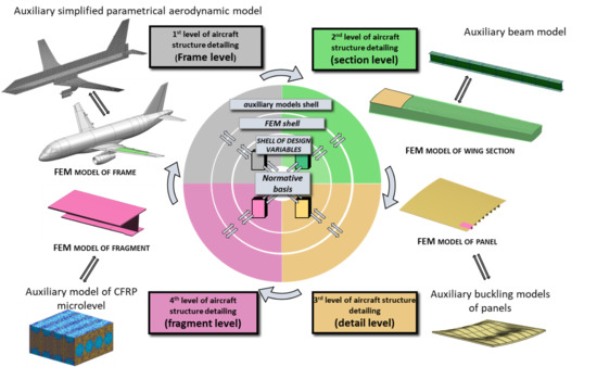
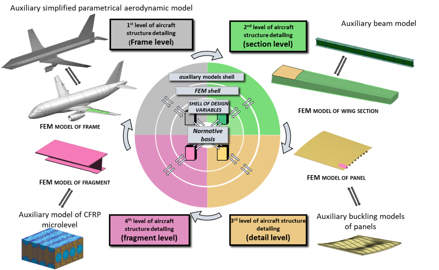
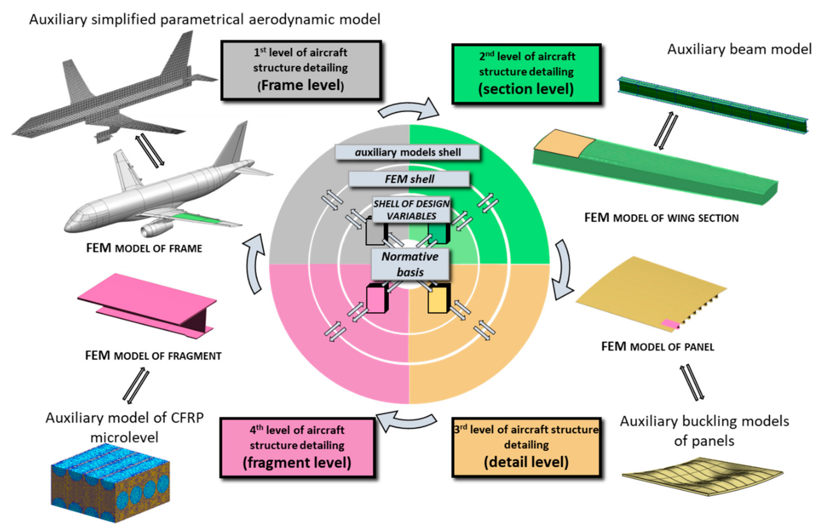
The main features of the base-version FLA are the following:
Global parameterization of airframe structure on the base of common special four-level database.
Four-level nested FE models according to detailing of the structure.
Full automation of initial data definition and analysis of calculations results.
Parallel solving strength tasks on both nested FE models and auxiliary analytical strength models.
Standard format of input and output data.
Full automation of the algorithm allows users to control the accuracy of a calculation, changing FE mesh size, and thus to find minimal possible nested FE model’s size.
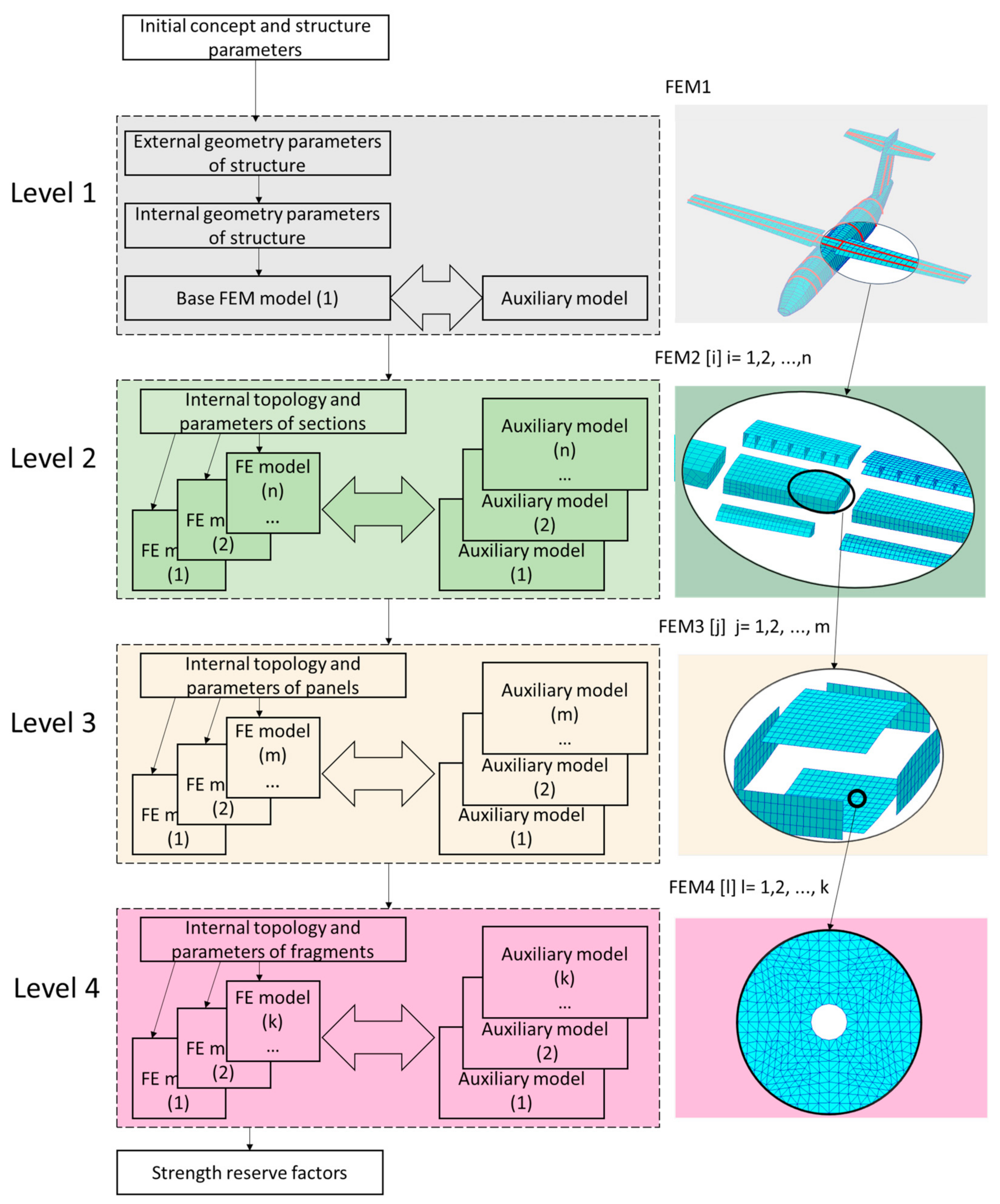
Figure 1 illustrates four-level structure decomposition and relationship between FE models and analytical ones.
As long as, during investigation of alternative variants of non-conventional airframes, the external geometry parameters of considered aerodynamic concepts did not have serious variation, the base FLA showed high performance [
13,
14].
In the present work, one more decomposition principle was developed, to decrease time and labor input for procedure of analysis of aerodynamic loads. In accordance with this principle of decomposition, a new aerodynamic module for the fast choosing of critical load cases was created and validated in the frame of the new version of FLA. This module divides aerodynamic load cases into several groups in frame of the iterative process of determination of critical load cases. These groups of load cases are investigated on aerodynamic models having different mesh size. The new version of FLA keeps all advantages of the base one.
Thus, the new version of the FLA realizes the three abovementioned principles of decomposition: four-level structure decomposition, decomposition of strength tasks, and decomposition of alternative load cases during the process of determination of critical load cases. It gives the possibility to decrease no less than 20 times the labor input (as compared to the base version of FLA) of complex strength analysis, keeping required accuracy. The new version is very suitable for strength analysis and airframe designing when researchers have to consider numerous numbers of alternative aerodynamic concepts, such as a big number of alternative variants of airframes within each of an aerodynamic concept.
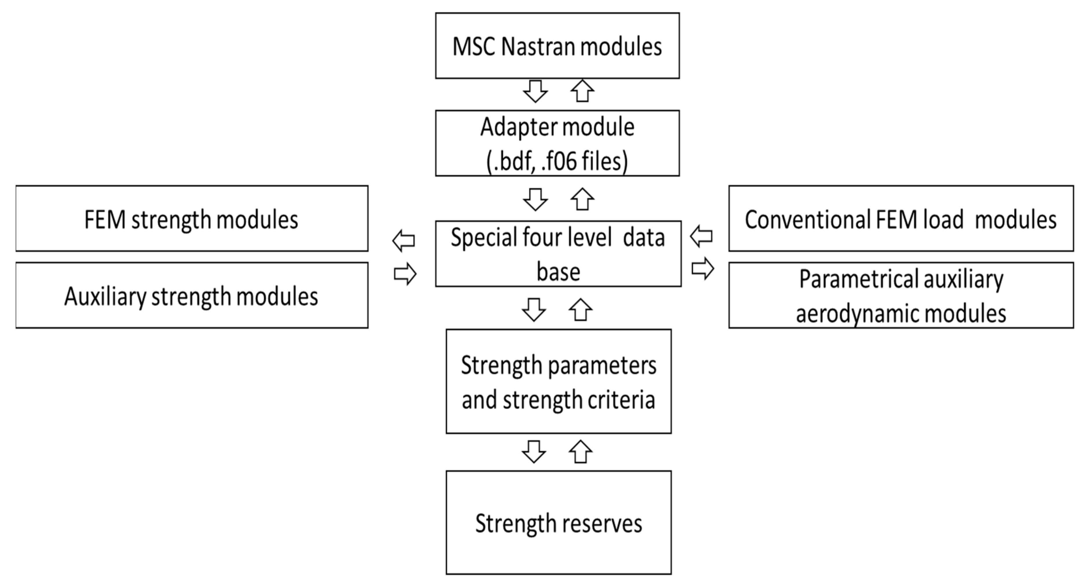
The structure of the new version of FLA consists of the following program modules: special four-level database modules, modules responsible for automatic building of parametrical FEM and auxiliary strength models, conventional FEM loads modules, modules for forming of parametrical aerodynamic load models, and modules responsible for relationship between four-level database and external numerical solvers. These modules were created and validated in TsAGI. In addition to the abovementioned modules, MSC Nastran program modules (SOL 101, SOL 144) were used as solvers for determination of stiffness and aerodynamic matrixes.
Figure 2 shows the scheme of process of strength analysis in the FLA.
2. Airframe Strength Analysis within FLA
The proposed FLA gives wide capabilities for reducing the time and labor input for complex strength-analysis procedures. That is very important for the preliminary design process of an aircraft airframe layout, as the check of strength constraints of numerous aircraft structure concepts is the most time-consuming part of the optimization procedure of designing.
Figure 3 shows the four-level airframe-strength models’ decomposition in strength analysis, when four types of FE models are used simultaneously (FEM 1, FEM 2, FEM 3, and FEM 4) in a strength analysis. Each of these models is responsible for solution of the corresponding strength tasks. Within FEM 1, the strength tasks related to the entire aircraft structure are considered, such as estimation of global stiffness parameters, load cases definition, aeroelasticity, etc. Within FEM 2 the tasks of global buckling and post-buckling behavior of main sections are solved. Moreover, detail mass estimations of fuel, equipment, payload is performed using strength models of this level. Within FEM 3, the tasks of global stress–strain state estimation and local (panel) buckling are carried out. In addition to strength analysis, the weight of structure can be estimated on the base of the FEM 3 model. Finally, FEM 4 is used for solving local strength tasks, e.g., for local stress concentration analysis in critical zones.
The FEM models of all levels have a strong connection with each other on the basis of the principle of nested models, when the models of the upper level include all nodes of the lower level models.
Thus, FEM 2 contains the main topology parameters of FEM 1 models, including the arrangement of sections into aircraft airframe. The number of FEM 2 models equals the number of sections, defined within FEM 1. Correspondingly, each of FEM 3 models include topology parameters of FEM 2 models, including arrangements of spars, ribs, panels into each section, etc.
The used principle of decomposition makes it possible to translate the correct boundary conditions from the lower level to the all the upper levels, as values of stresses and strains, defined on the base nodes (on the FEM model of the lower level), are automatically transferred to the models of upper levels. Thus, it gives possibility to solve tasks piecemeal with correct boundary conditions. It can decrease significantly time and labor input during the calculation.
In the frame of FLA, it is easy to realize decomposition-of-strength tasks because auxiliary strength models are built automatically, using the same parameters as FEMs. The auxiliary models are usually used at the first steps of strength analysis of the airframes, whereas the FEM models are used at a later stage. Auxiliary-strength models can be included into FLA, as modules working in parallel. It is very suitable for the fast solving of the tasks of aeroelasticity and determination of aerodynamic loads.
In this paper, parametrical auxiliary aerodynamic models are used, together with parametrical auxiliary beam models, in order to separate quickly non-critical load cases from the critical ones. The critical load cases are investigated by means of more detail FEM strength and aerodynamic models. In this work, only metallic airframes were considered, so no microlevel models were used in calculations. The local-level FEM models responsible for fatigue were not considered, too. Two-dimensional triangle FEs with three nodes topology and linear approximation function were used during calculations. Linear dependency between stresses and strains was assumed during the calculations.
3. Parametrical Auxiliary Aerodynamic Model for FLA
In this work, a set of modifications of the basis variant of the FLA was carried out, related to development and validation of the simplified auxiliary parametrical aerodynamic model (SAPAM).
It should be mentioned that, in the frame of the basis FLA, aerodynamic loading data were considered as an initial data that should be imported from external sources or could be calculated in the frame of a detailed aerodynamic model—that is quite time-consuming for calculations of numerous variants of a concept with various external geometry.
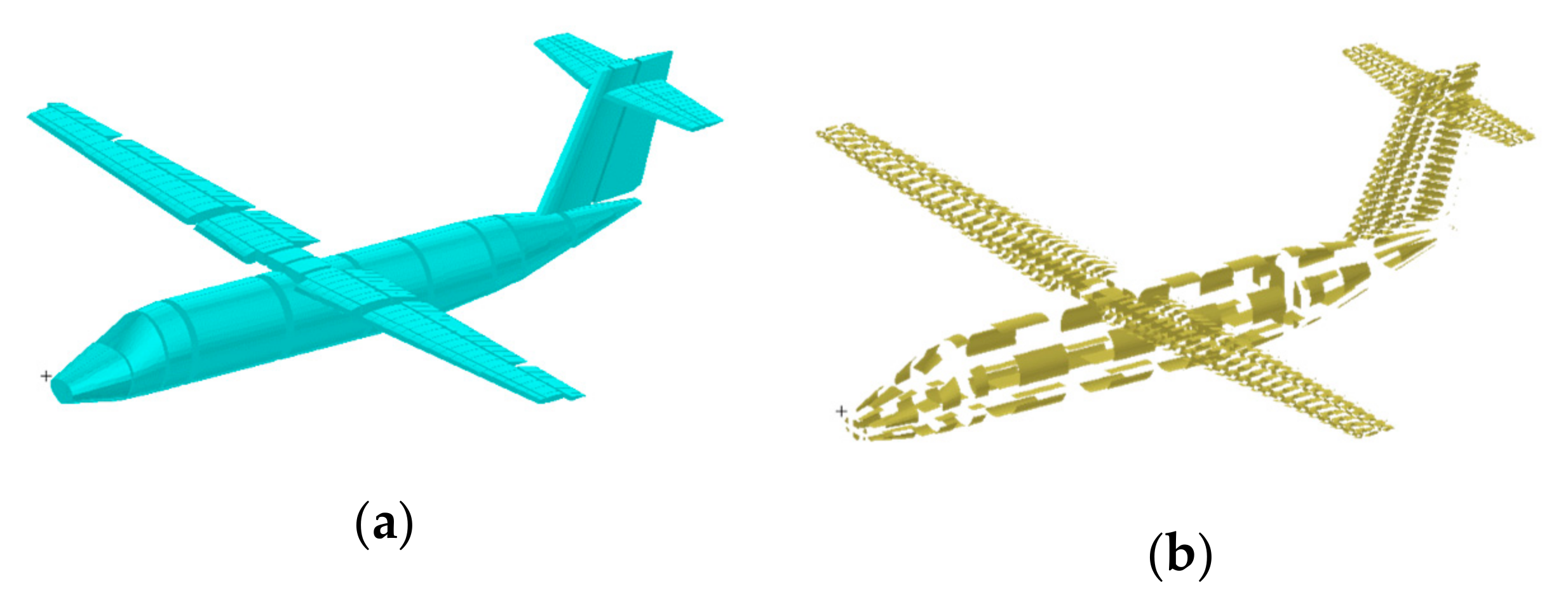
The modified FLA includes SAPAM based on the doublet lattice method (DLM) [
15,
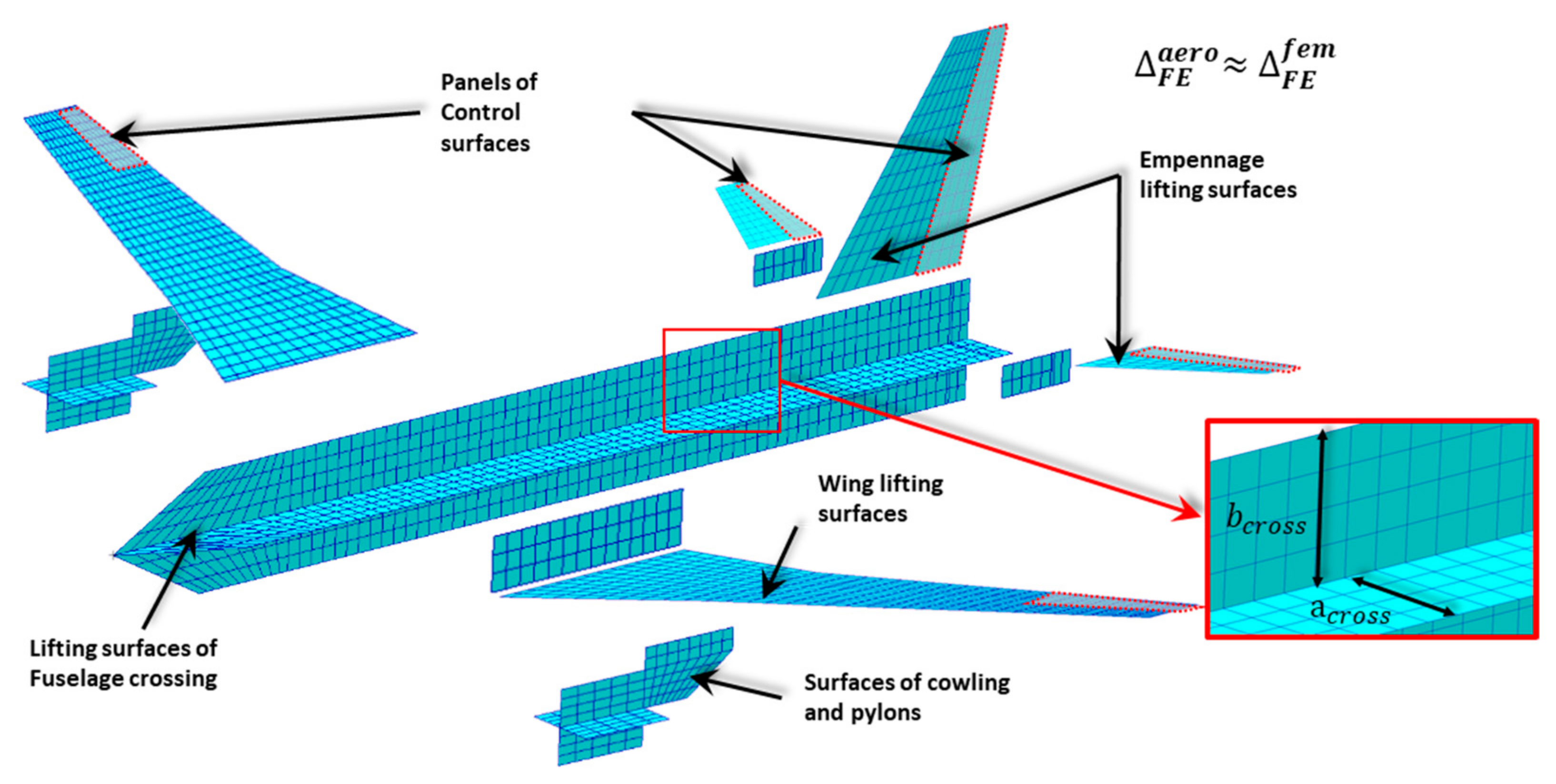
16]. In frames of SAPAM, lifting surfaces of wing and empennage are modeled by plates, consisting of thin panels, while axisymmetric bodies (e.g., fuselage and engines) are modeled by crossing surfaces, that also consist of thin plates (
Figure 4). Height and width of crossing surfaces are related explicitly with height and width of axisymmetric body by means of the parameter
. In this work, the standard value of
parameter equal to 0.85 is taken. The typical size of panels of SAPAM is a parameter. The value of the parameter depends on the needed accuracy.
The process of generation of SAPAM is as follows:
Building of surfaces of fuselage crossing,
Building of lifting surfaces of wing and empennage,
Building of “bridges” for correct fluid motion,
Building of surfaces of cowlings and pylons,
Setting of control surfaces from range of lifting surfaces.
SAPAM was connected with the FEM model in an automated mode. Point finite elements, which are model masses, were added into the four-level model for the balancing of aerodynamic forces and moments via inertia forces and moments. Point elements model masses were for the following:
Structure,
Fuel,
Payload,
Equipment and facility,
Power unit,
Landing gear.
In this work, SAPAM and structure-nested FEM models for regional aircraft structures have been built in frame of MSC Nastran [
17,
18].
In
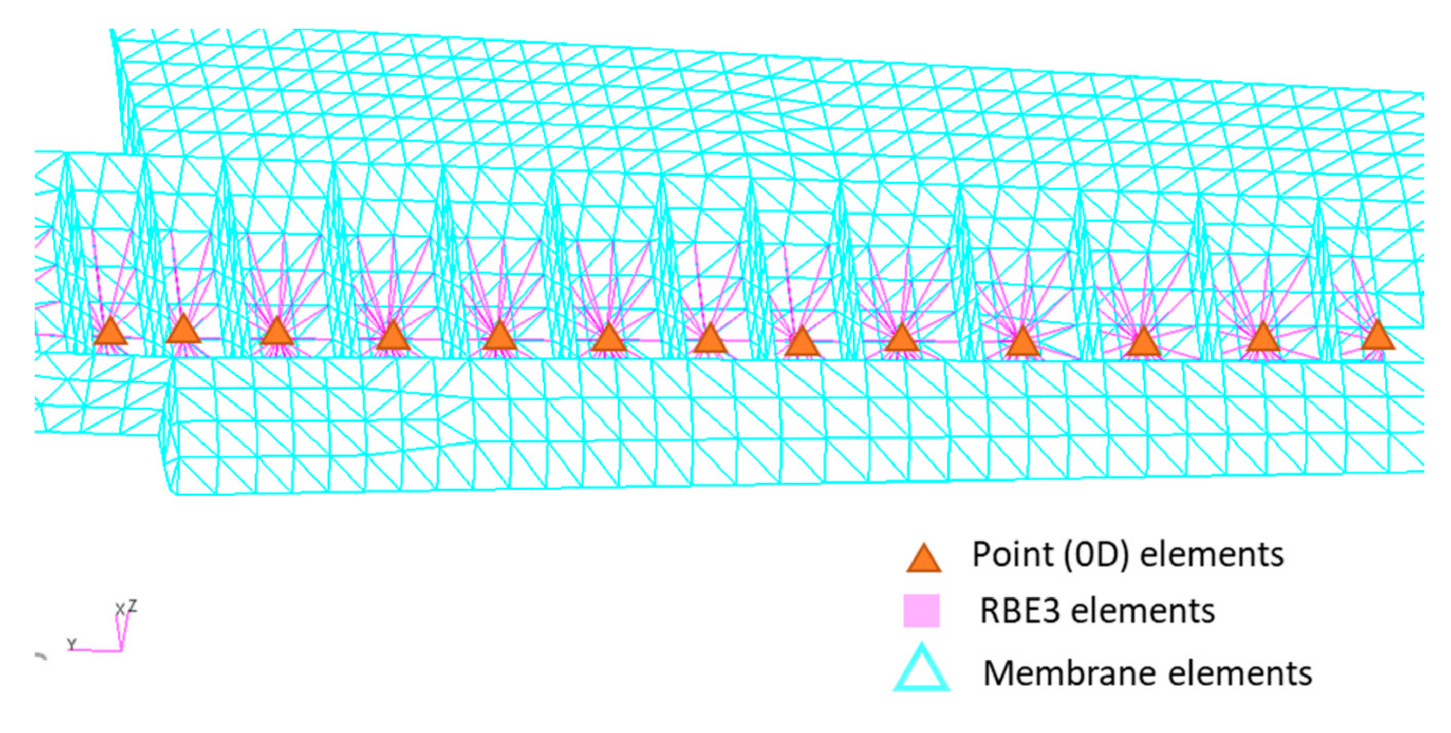
Figure 5, the modeling of inertia loads, created by fuel in a lateral wing, is shown. Forces for each point of a flight are applied to nodes of point elements, which are calculated by taking into account overloads, angle velocities, and angle accelerations. These forces are distributed to other nodes of the first level of the nested FE model via RBE3 finite elements. Using this type of finite elements make it possible to distribute loads correctly because they do not disturb the stress–strain state of the nested FE model.
4. Validation of SAPAM within the FLA
The main scope of the validation was to check the reliability and calculation performance of the modified FLA, namely the SAPAM module being one of the key parts of the algorithm defining its performance and the connection check between the modules of the modified FLA.
Within the validation of the modified FLA, parametrical investigations on a number of alternative variants related to the base variant of hypothetic regional aircraft were carried out. General characteristics of the base variant of the regional aircraft are listed in
Table 1. The considered alternative variants differ from the base one by the following active design parameters: wing aspect ratio, wing relative thickness, wing twist, and no/yes wing strut. The wing surface area was kept constant within the investigations.
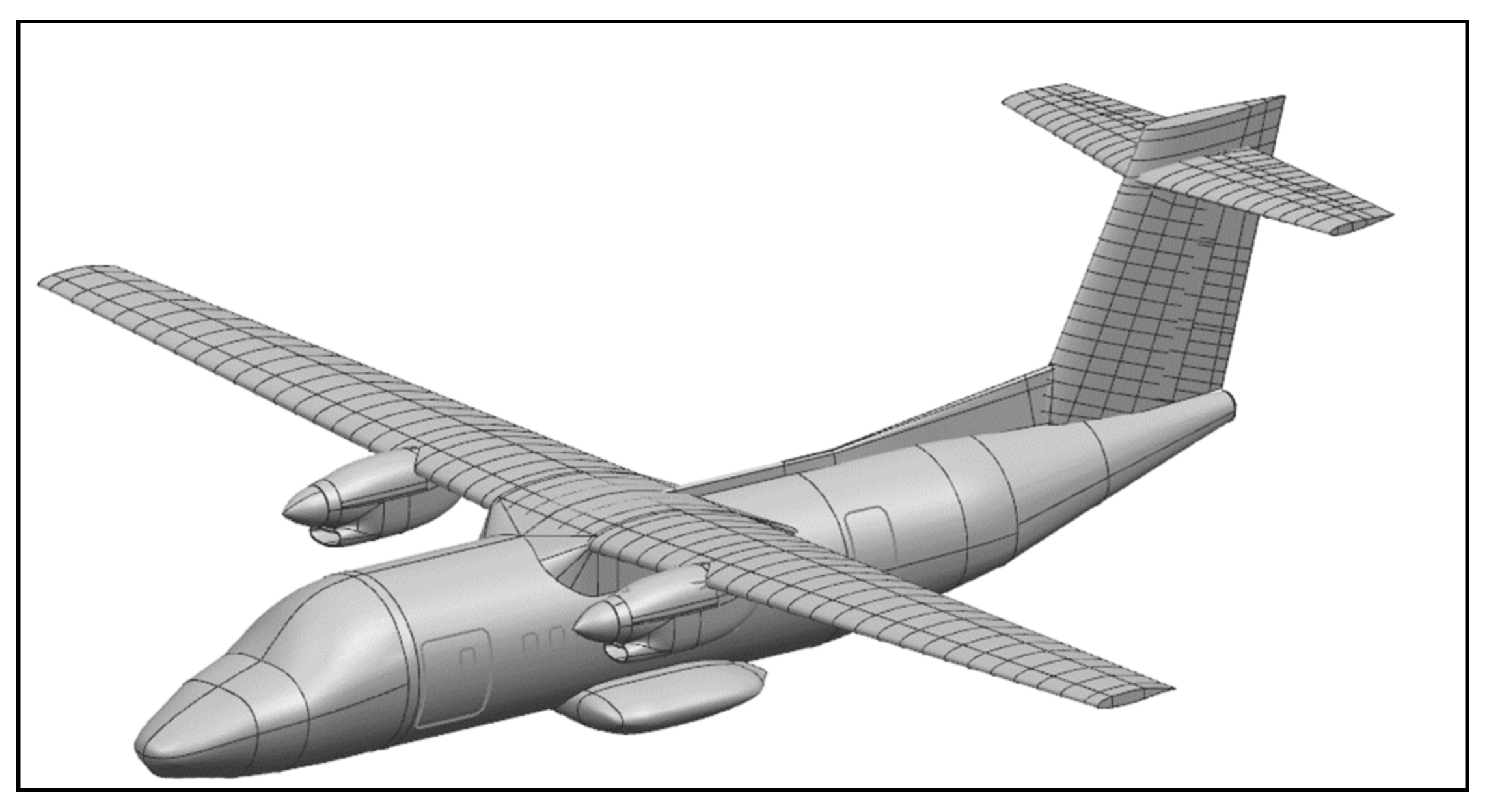
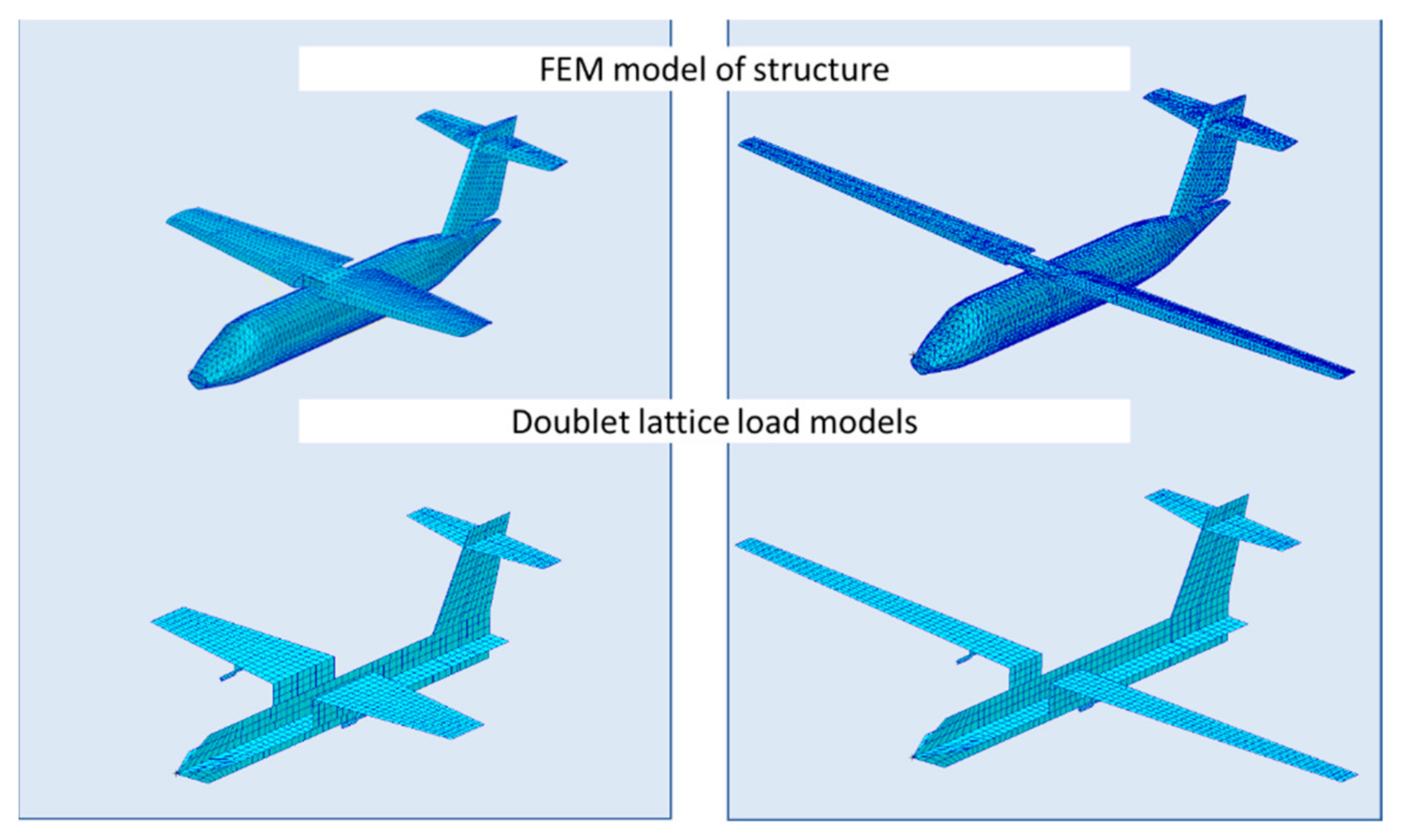
The structure model of the base variant of the aircraft is shown in
Figure 6. It corresponds to the first level of detailing according to decomposition principles described in
Section 2.
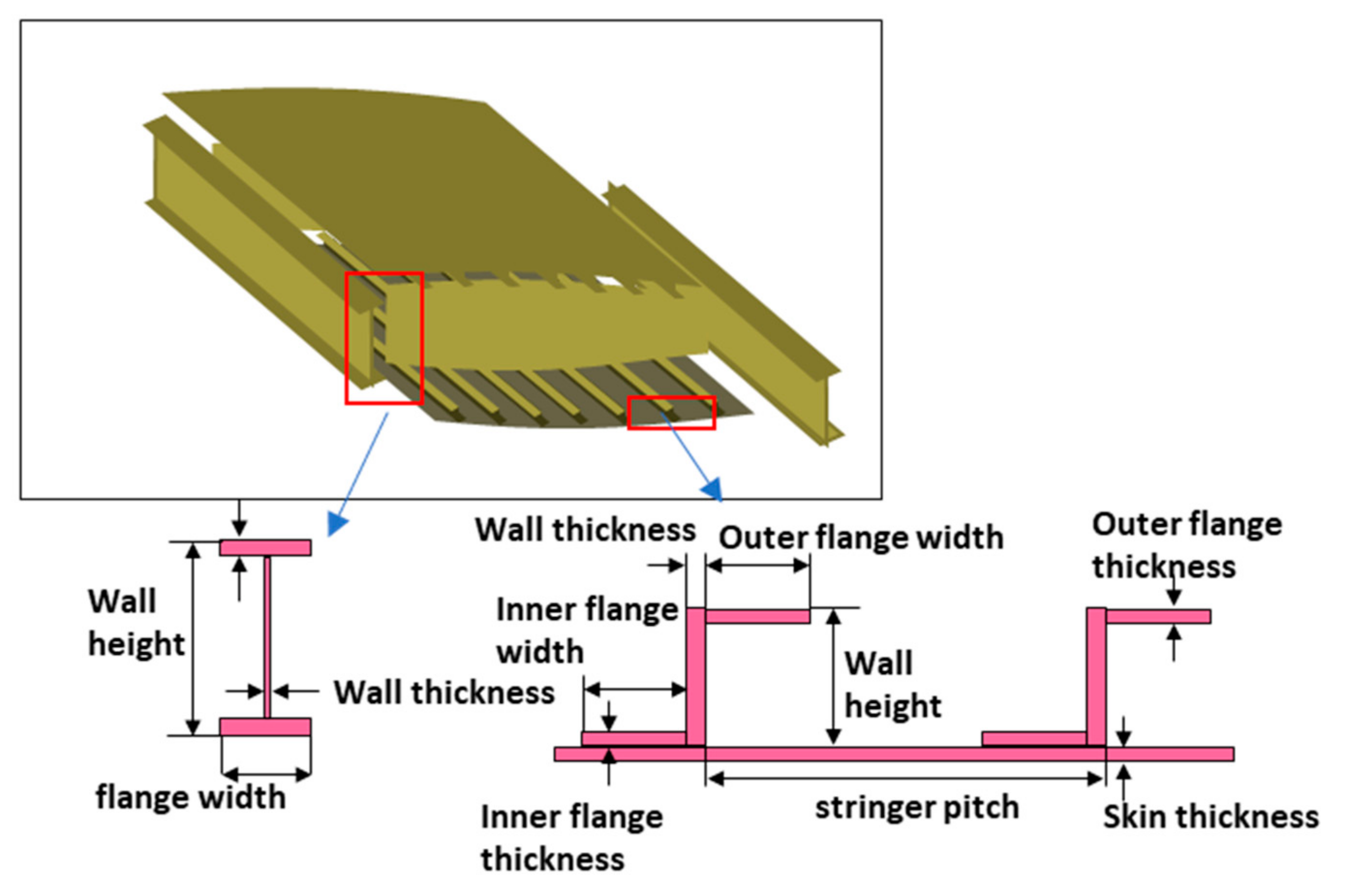
The scheme of detailing of the base configuration is illustrated in
Figure 7, while the scheme of detailing at the second level (sections) and the scheme of detailing at the third level (details) are shown on
Figure 6a,b correspondingly. The scheme of detailing, corresponding to the fourth level (fragment), is illustrated on
Figure 8.
The first step of validation investigations was to check that the simplified model is capable of correct calculation of aerodynamic parameters for variable external geometry. In these investigations, the aspect ratio of the wing was varied at the constant wing area. Each of alternative variants was considered by means of the same automated calculation procedure. The procedure included forming the four-level FEM model, calculation of aerodynamic and inertia loads, definition of strength parameters and reserve factors, and structure optimization with preliminary weight estimation. Each variant of a structure was optimized, taking into account numerous strength constraints, including stress/strain reserves, buckling factors, and displacement constraints. Within the validation, typical aluminum alloy used in current civil aircraft structures was considered as a structure material (
Table 2).
Four flight loading cases (
Table 3) were considered. Such load cases are the most critical for such a kind of wing structure [
19]. These load cases were selected in order to compare different variants of the wing’s external geometry in the same aerodynamic conditions. Structure parameters obtained during optimization for the considered load cases were used for definition of stiffness characteristics for the further strength analysis procedures.
Variations of the wing aspect ratio were performed within the range from
to
(
Figure 9). For each variant, wing area was a constant, as well as parameters of fuselage and empennage. Wing chords and wing thickness were decreased proportionally with the increasing of the wingspan.
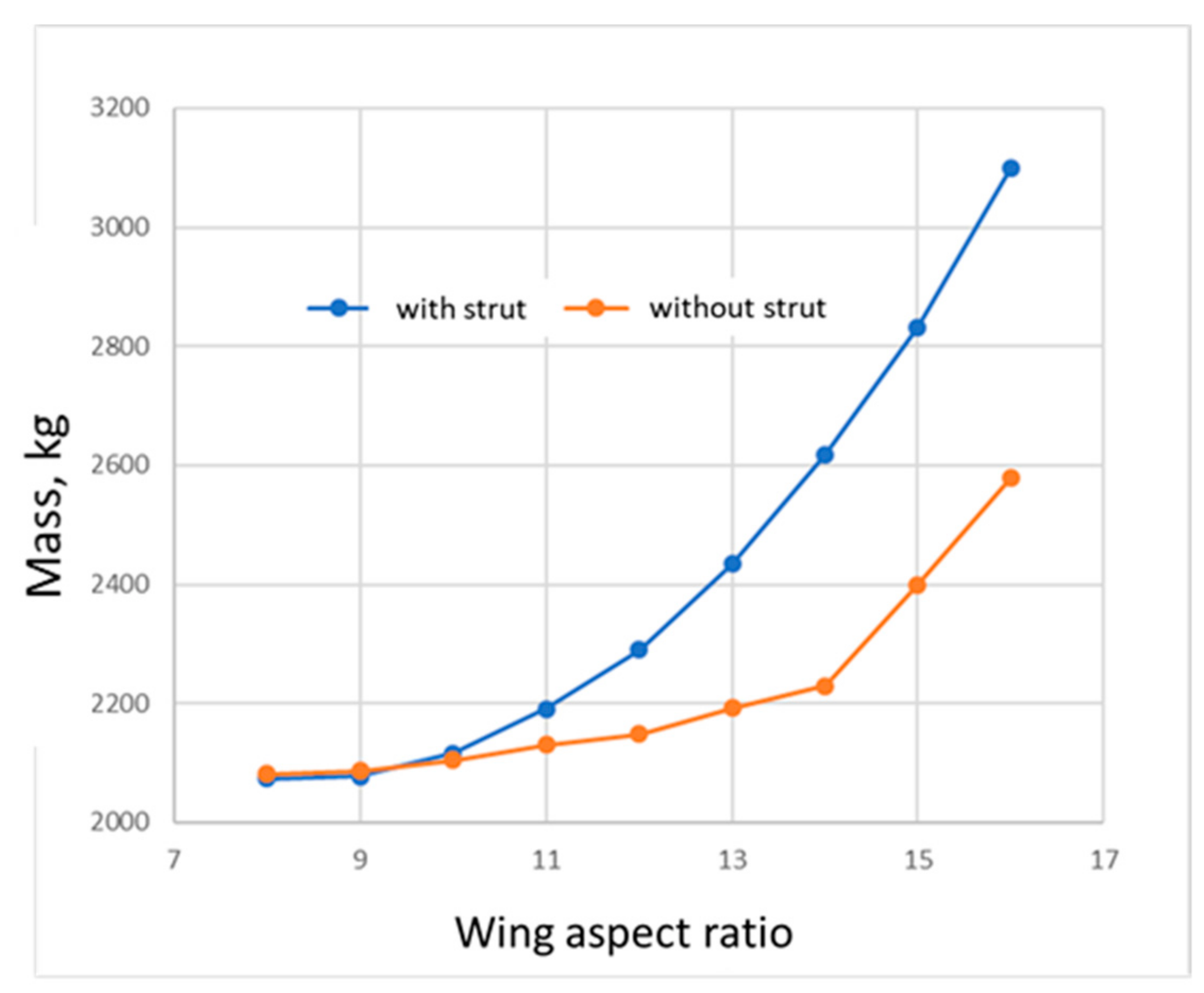
In addition, non-conventional structure layouts with strut were considered. The graph (
Figure 10) shows dependency of mass of optimized structure of airframe vs. wing aspect ratio for two variants of structure layout with and without strut. The attachment point of wing with strut was situated at 55% of a semi wingspan.
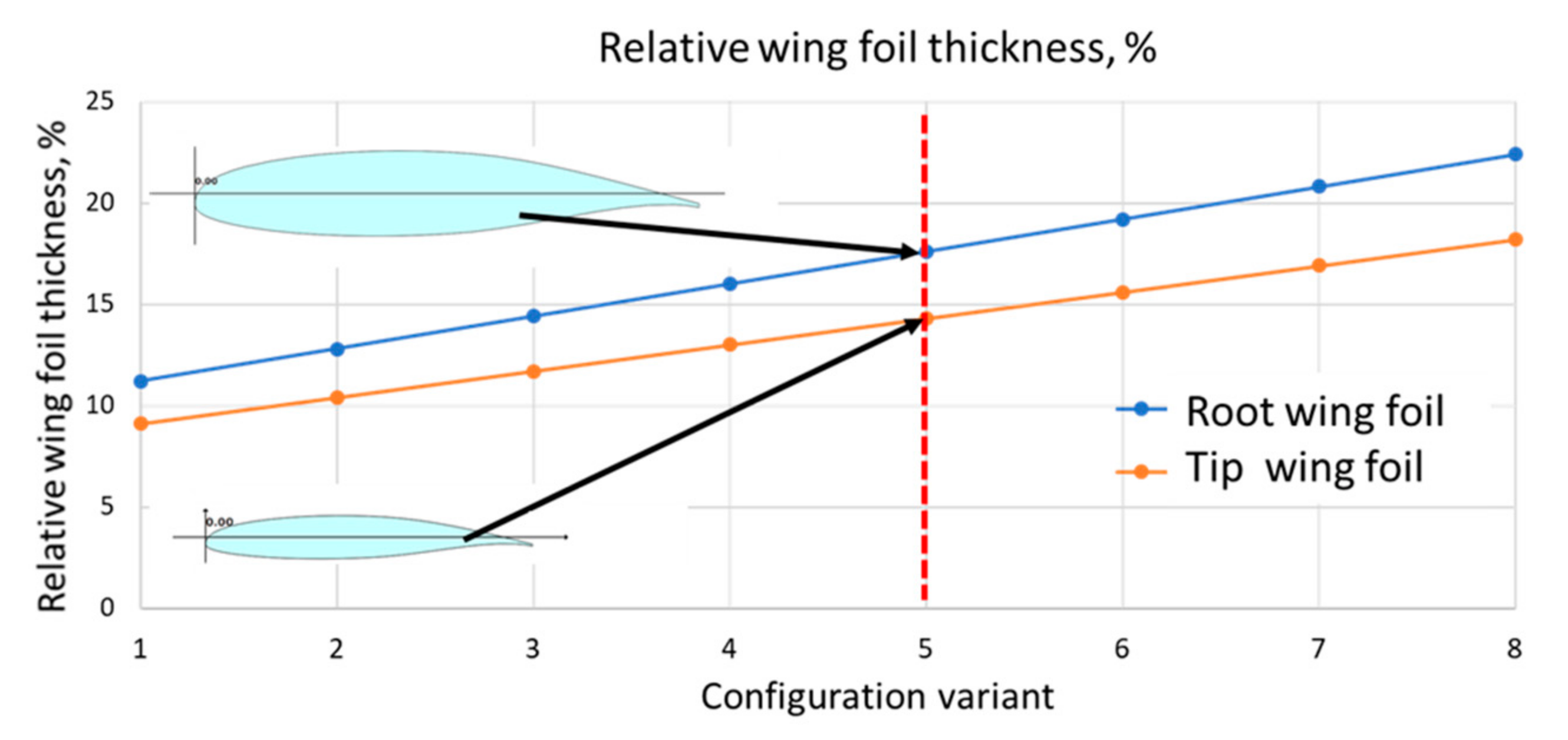
In the graphs, weight of the wing with strut is shown relatively to the weight of the wing without strut. In the frame of validation of the modified FLA, relative wing airfoil thicknesses for the base configuration of regional aircraft were varied (
Figure 11). Variations of a wing airfoil thickness were carried out within the range from 70% to 140%, as related to a wing thickness of the base configuration.
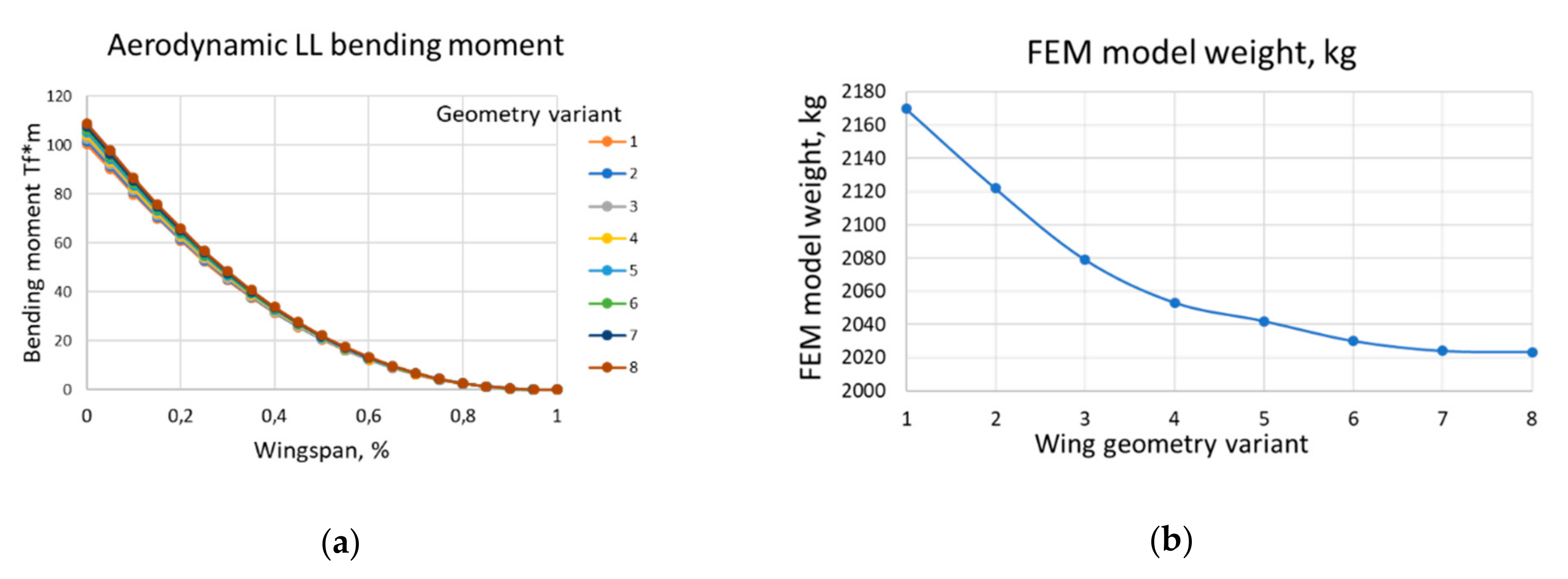
Dependencies of the bending moment applied to the wing for the most critical load case LC2 are illustrated on the graph in
Figure 12a. As shown on the graph, influence of a wing stiffness on a wing loading is not essential. The weight of the airframe decreases with the increasing of wing thickness (
Figure 12b).
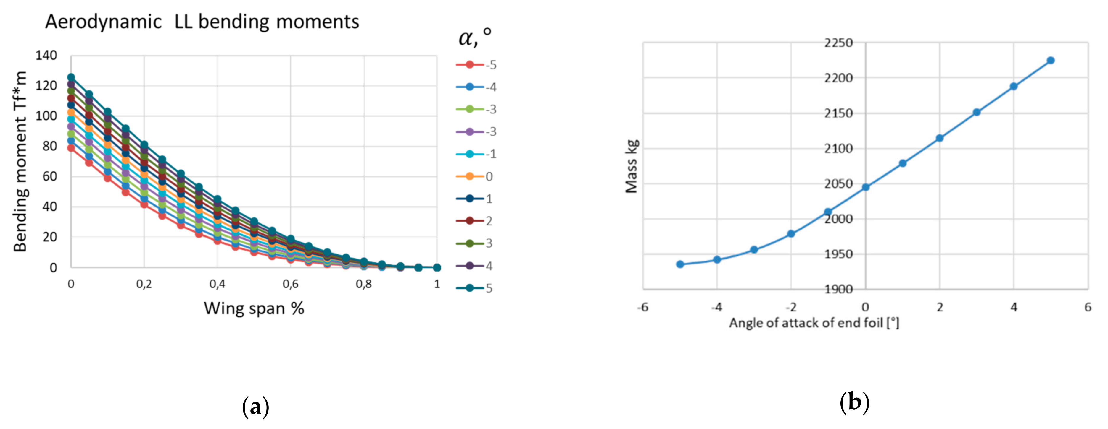
In a similar manner, wing twist was varied (
Figure 13). Angle of attack of a tip foil of the wing was varied in a range from
to
. Angle of attack of a root foil of the wing was constant during this procedure, and foils between the root and the tips were formed by a linear interpolation. Dependencies of bending moment applied to the wing for the most critical load case LC2 are illustrated on the graph (
Figure 13a). Increasing of the angle of attack of the tip wing foil causes increasing of bending moments applied to the wing. The mass of the airframe increases with the increasing of the angle of attack of the tip wing foil (
Figure 13b).
Within the validation of the modified FLA, high performance of the SAPAM module was demonstrated.
5. Validation of the Modified FLA as a Part of Design Procedure
For validation of capabilities of the modified FLA, with a focus on the speed of calculations, numerous strength analyses of alternative variants of wing structures of the hypothetic regional aircraft were carried out.
In this investigation, three variants of wing aspect ratio were considered. In addition to the base variant with
(which corresponds to the base variant of the aircraft illustrated in
Section 4), two more alternative variants with higher aspect ratio (
) were considered.
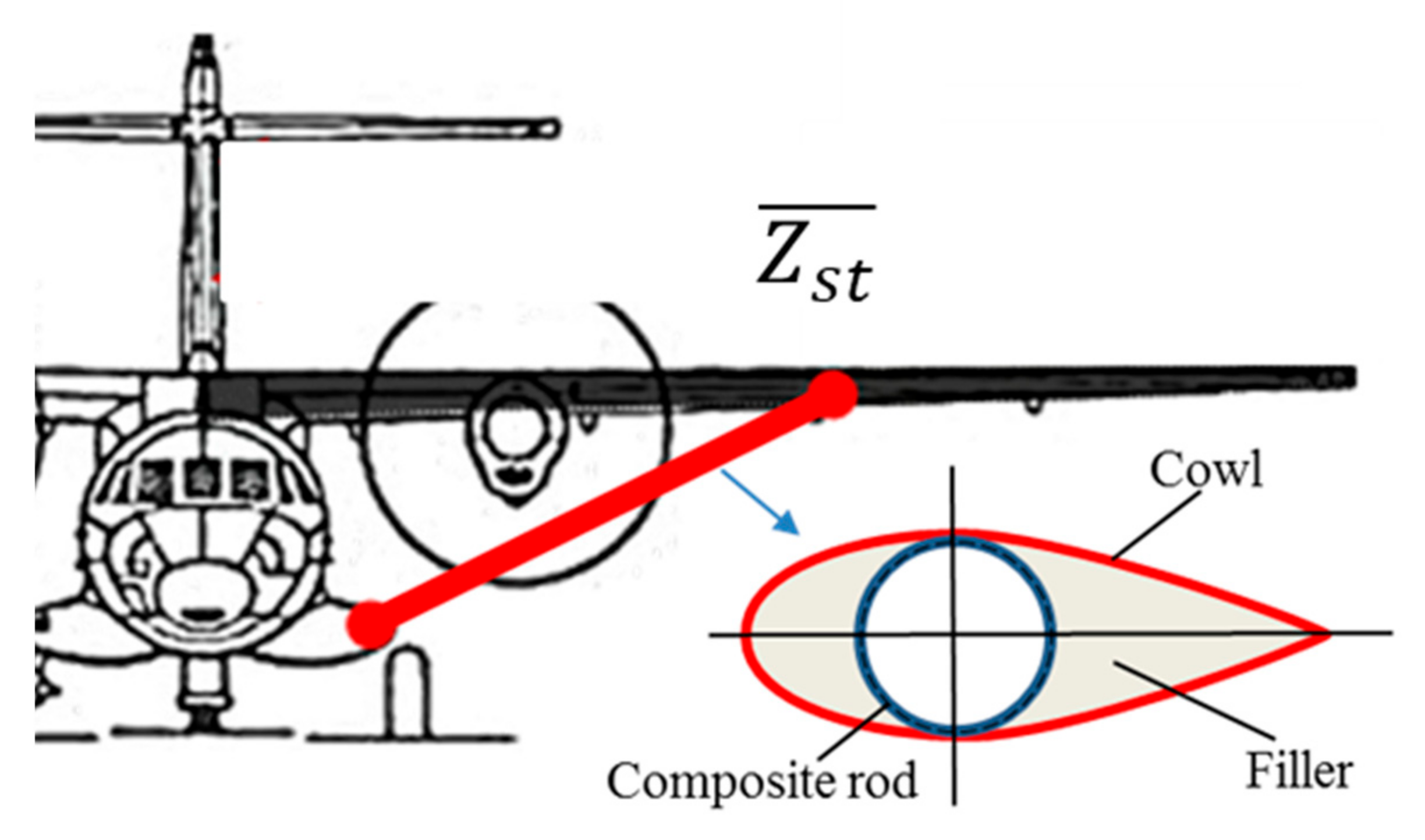
For these variants, parametric dependencies of weight of structure of wing from position of joint aggregate on wingspan (
) were obtained. The scheme of parametrization of the model of the regional aircraft with strut for one variant of wing aspect ratio is illustrated on
Figure 14.
As shown on
Figure 14, wing strut is a rod with a thin wall (metal or metal-composite). In this work, local and global buckling of the strut were estimated [
20,
21].
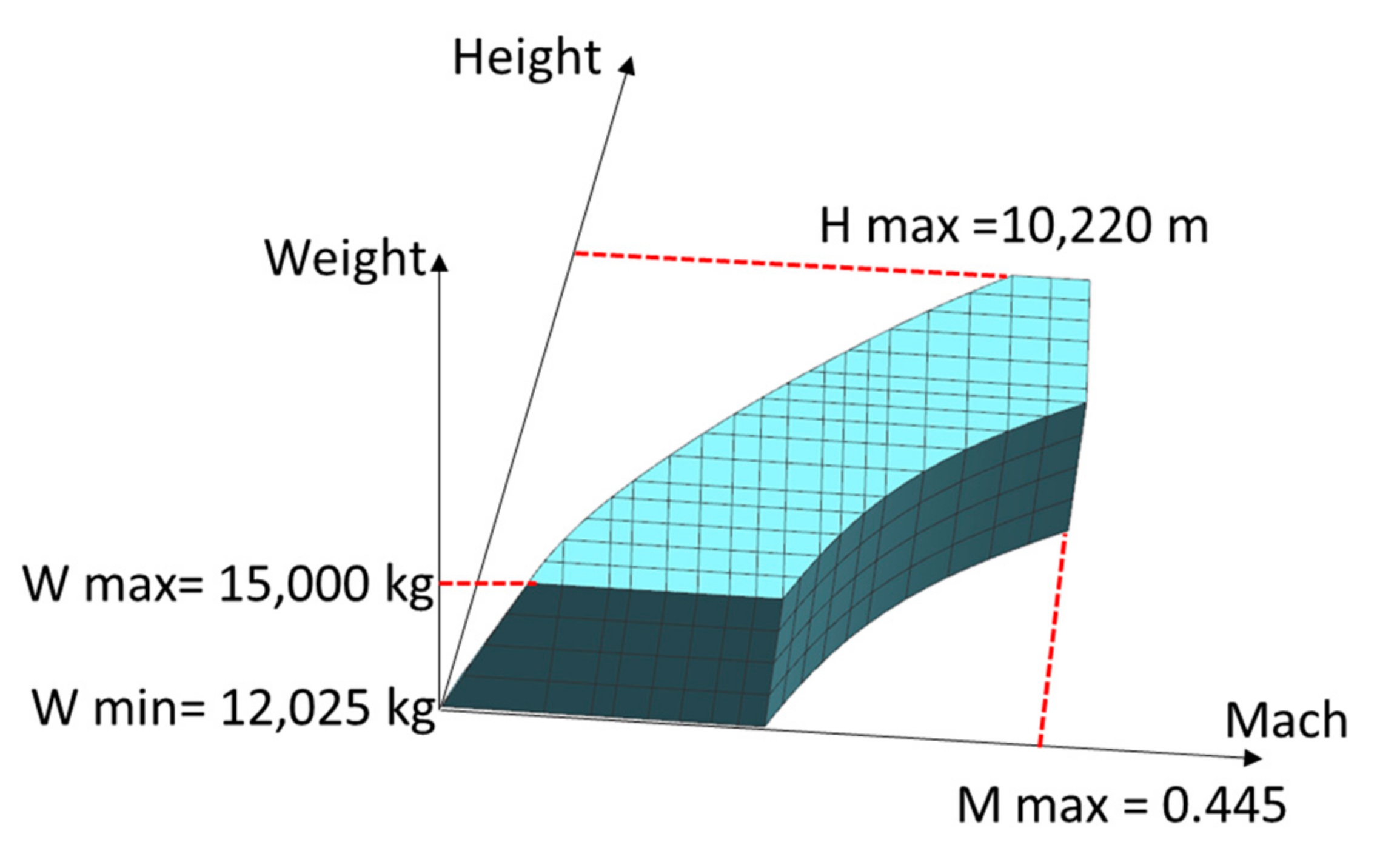
Analysis of load cases, which are critical for wing structure, were carried out by using the modified methodology of load analysis. Discretization of feasible range of flight regimes was carried out in space Height–Mach–Mass (
Figure 15). Load estimation was carried out in each point, for symmetric maneuvers (max and min overcharge) and gust influence. The parameters of the structure layout that were obtained were used as start parameters during the analysis of loads for each variant of wing aspect ratio. Discretization extent is also a parameter of fourth-level model (parametrized by weight, Mach, and Height step).
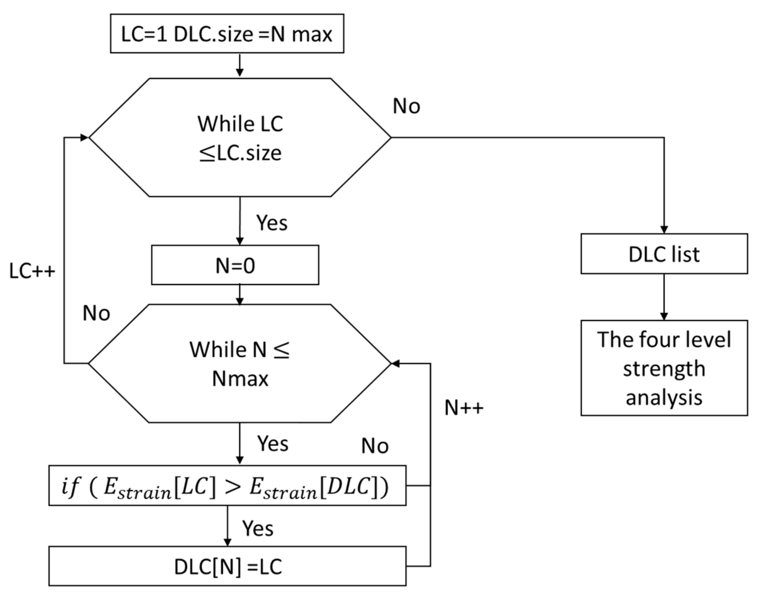
Thus, about 500 points from the feasible range of flight regimes were investigated (three load cases for each point). Searching for design load cases (DLCs) from a set of load cases (LC) was carried out by the strain energy criteria. The strain energy was calculated by using auxiliary beam model of a wing. In this paper, the number of DLCs is equal to amount of control sections of the beam model (N max). LC should be considered as a DLC, when it has a maximum value of strain energy at least in one beam control section (N—index of control section) (
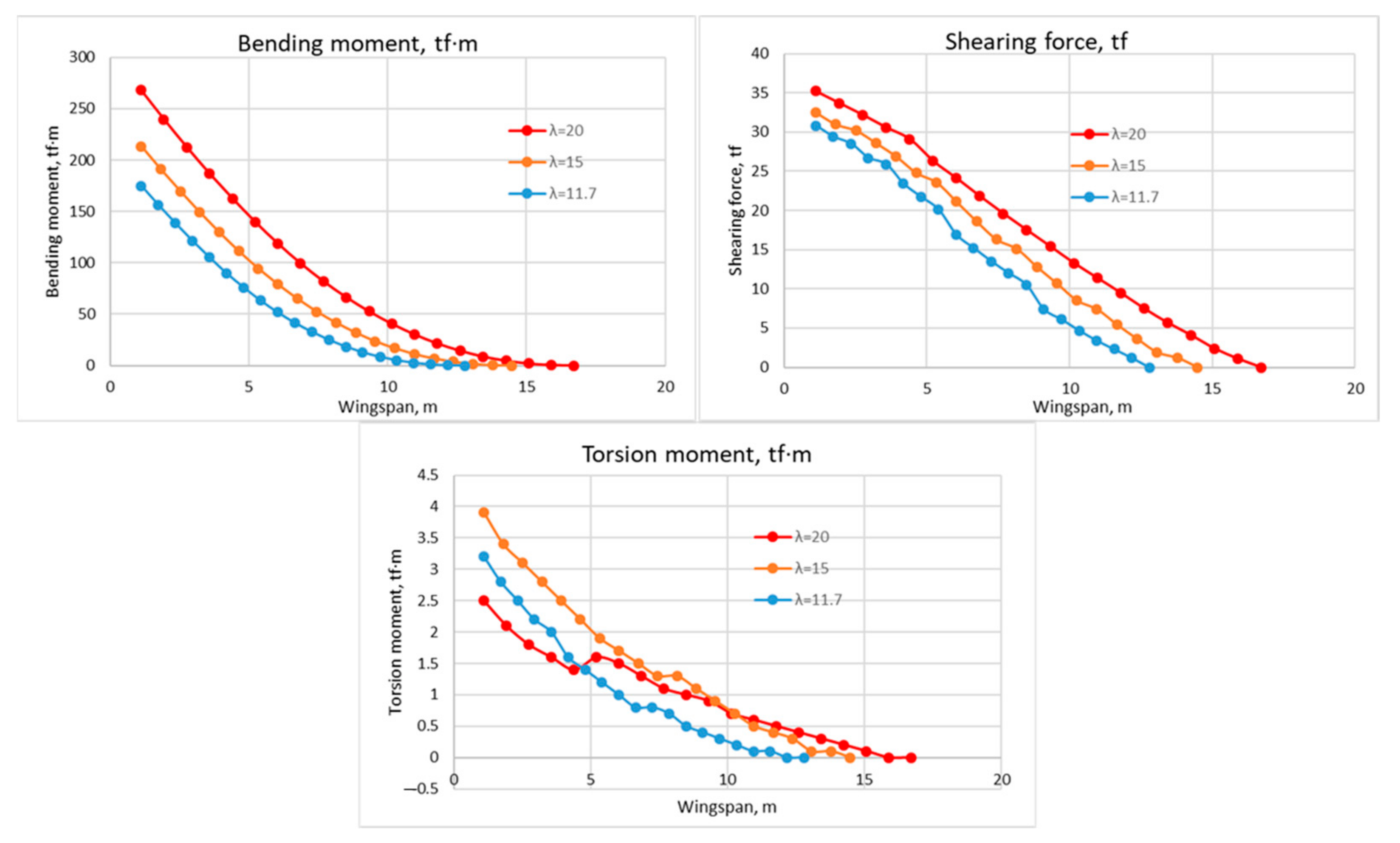
Figure 16). Envelopes of distributions of ultimate bending and torsion moments and shearing forces for most critical load case (gust loads) are illustrated in
Figure 17, for each variant of wing aspect ratio of the regional aircraft. Relative weights of the wing, as compared to the base variant of the wing without strut, for three variants of wing aspect ratio, are shown in
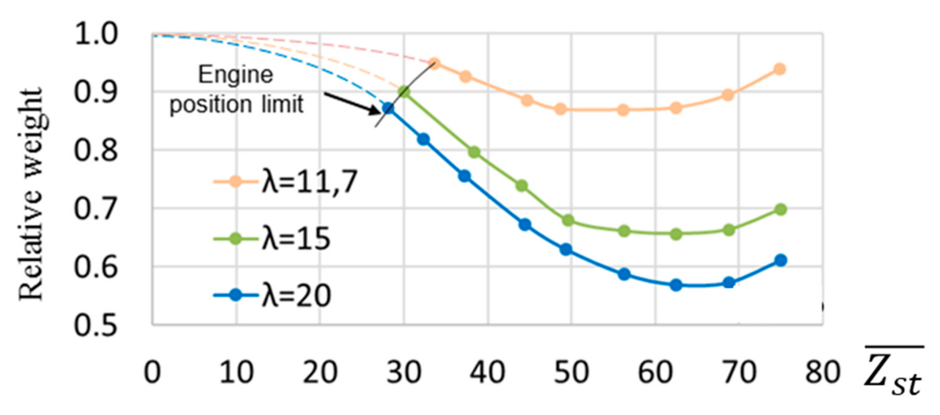
Table 4. Dependencies of relative weight of the wing with strut on parameter (
) (for three variants of wing aspect ratio) are illustrated in
Figure 18.
The graph (
Figure 18) shows that rational value of parameter
is equal to 50–65% of semi wingspan. Two variants of wing are rational by weight—base variant with strut (87.7% from base variant without strut) and modified variant
with strut (93.3% from base variant without strut).
6. Time Efficiency of the FLA of Strength Analysis
The simulations were carried out on the workstation controlled by a central processor Intel I7 7700 K. An analysis of labor intensiveness of strength analysis of regional aircraft structure for the base variant configuration is shown in
Table 4, for the conventional approach and the FLA.
A report for the computational capability for one iteration of strength analysis for one configuration of regional aircraft for different discretization (different size of finite element) of FEM model is illustrated in
Table 5.
In the frame of parametric investigations, the meshes of FEM models were chosen by the condition of the same allowable maximal error of calculation strain energy.
Table 6 shows relations between strain energy and FE mesh size for the base variant of the regional aircraft. The error equals ~5% was chosen as the limit for all variants during parametrical investigations.
It should be noted that the parametric investigations in this work were carried out in parallel mode (each geometry configuration simulated in a separate stream).
One of the main advantages of the FLA for its implementation into the preliminary stage of aircraft design is that the labor-saving can be provided not only by means of calculation-time reduction, but also by selection of sparser mesh for initial iterations in the search for rational parameters, and more coarse mesh for getting a more accurate solution on later iterations within the chosen range of variants of aircraft concepts.
7. Conclusions
The FLA of complex strength analysis of airframe based on the three decomposition principles, namely structural decomposition, strength task decomposition, and decomposition of alternative variant of load cases, was validated successfully on a wing structure of the hypothetic regional aircraft. The validation was focused on the developed module for fast automated calculation of aerodynamic parameters of load cases. During the calculations, high efficiency of the algorithm, both in searching rational balance between accuracy and calculation time and in choosing critical load cases for alternative concepts, was confirmed.
Parametric investigations carried out in this work have proven that the usage of the algorithm can provide no less than a 20-times decrease of calculation time, required for strength analysis of wings of regional aircrafts, as compared to conventional methods of strength analysis.
Within the validation of the modified FLA, the parametrical dependencies of weight of wing on geometrical parameters of strut-braced high-aspect-ratio wing of a hypothetic regional aircraft were obtained. The rational range of points for connection of strut and wing, corresponding to minimal weight characteristics of wing was found. The positive validation results can become a background for further development of the FLA for preliminary design procedure.


 ,
, 


