1. Introduction
There is an increasing demand for low-cost and small launch vehicles for scientific suborbital missions and dedicated orbital launches of small satellites. A large rocket is suitable for launching many satellites into a single orbital plane to form a constellation. However, small rockets are required for the dedicated launching of a small number of payloads into various orbits, including scientific missions. The world’s smallest orbital launch vehicle is the Japanese SS-520-5, with a mass of 2.6 t [
1,
2]. It comprises three solid-propellant stages. However, the payload ratios of small rockets are lower than those of large rockets. The ratios can be significantly increased by performing air launches, where the rocket is launched into the air from an airplane or balloon [
3,
4]. Airplane-type air launches have been used throughout the history of rocket launches. The idea originated from an air-launched ballistic missile, Bold Orion and High Virgo, developed in the 1950s [
5]. The Pegasus rocket is the first orbital rocket that was air-launched from an airplane and many commercial flights have been performed. Recently, Virgin Orbit performed the first successful air-launch of a liquid-propellant orbital rocket. Thus, theories and technologies for airplane-type air launches have been established at a practical level.
A method of launching a rocket using a launcher suspended from a balloon is referred to as rockoon. It presents the advantage of launching from a high altitude exceeding 20 km, which is not possible by using civil aircraft. Because of the limitation of the balloon’s volume, rockoon only applies to very small satellites and suborbital missions [
6]. The problems associated with rockoon have been addressed in previous studies. The first experiment of rockoon was performed by a group under Van Allen in the 1950s with the aim of performing suborbital science missions for studying high-altitude atmospheres. The launcher was not equipped with a device to control the azimuth angle during launch. Hence, the balloon had to be launched from a vast desert or a ship that was isolated to the maximum extent from inhabited islands. Sigma rocket [
7] was a Japanese rockoon that reached an altitude of 105 km in 1961. However, the program ended because of cost issues. In the USA, JP Aerospace [
8] and California Maritime Academy [
9] used tube-shaped launchers that were lifted by multiple balloons. The former rockoon performed successful launches while the latter exhibited problems related to limited helium supply. In Australia, HARP performed some rockoon launches [
10]; however, the uncertain winds in Woomera posed problems in releasing a balloon and they concluded that the location was unsuitable for rockoon launches. Single- and two-stage rockets were successfully launched from a rail launcher lifted by balloons (developed at the University of Washington [
11]), allowing the entire launcher system to be recovered, undamaged, to the ground in the single-stage mission. Although rockoon technologies have been gradually improved, major problems still exist in the attitude control of the launcher in the air and the high costs of solid propellant rockets and helium gas [
12].
With respect to attitude control, the aforementioned rockoon systems used a suspended launcher without an attitude controller. In the HIMES project in Japan [
13], the gondola suspended by a balloon was equipped with a reaction control system that used gas jet thrusters to control the azimuth angle. The rocket was ignited during free fall, soon after release. Because it is difficult to accurately predict the attitude of a falling rocket at ignition, the application of a rail launcher is preferable. However, the issue of the attitude disturbance of a suspended launcher still exists, especially in the azimuth angle. Wind gusts have small effects on the attitude disturbances because the gusts in the stratosphere are weak and the relative speed of a balloon to the air is small; however, the azimuth angle is easily affected by a small perturbation and pendulum motion of the balloon because it does not have an equilibrium angle. Nevertheless, the azimuth angle has never been controlled in previous rockoon projects. Attitude control technologies of gondolas on balloons have been researched in the balloon-borne telescope system [
14,
15]. A suspended telescope was oriented to the target direction with an accuracy of one arcminute using a control moment gyroscope (CMG) as the attitude control device. There exists a coupling of pendulum and azimuth dynamics through the azimuth control loop and a complete dynamic model of balloon-borne systems was proposed [
16].
There are two differences between a balloon-borne telescope and a rockoon launcher. First, the center of gravity (CG) of the rockoon launcher moves as the rocket slides on the launcher rail and the mass suspended on the balloon decreases after the rocket leaves the launcher, causing dynamic behavior with respect to the elevation angle. Second, a friction force at the sliding point between the rocket and launcher leads to fluctuations in the attitude of the launcher. Even in ground launches, the nose-down movement of a rocket leaving from the end of an inclined rail launcher significantly affects the trajectory parameters, such as apogee altitude, impact point downrange, and maximum dynamic pressure. This becomes more significant for a suspended rockoon launcher because the attitude of the rail is not constrained to the ground. Thus, the dynamics and attitude control of a suspended launcher at launch is a major problem associated with rockoon; however, these problems have never been investigated.
In our rockoon project, we aim to launch a hybrid rocket from a stratospheric balloon for suborbital science missions and future satellite launch missions. A single-stage rocket with a mass of 190 kg will be ground-launched in 2022. It has been converted to an air-launch configuration to be launched from a balloon. They are finally extended to a three-stage orbital rocket with a mass of 771 kg. As reported in our previous study [
17], a hybrid rocket using N
2O propellant is suitable for a high-altitude rockoon, because N
2O can be stored in liquid state at the temperature of the atmosphere, preventing the heat conduction through the tank wall. The tank pressure decreases as the propellant is cooled by the atmosphere. The lower limit is 0.7 MPa, that is, the saturation pressure at the air temperature at 20 km of altitude. It is too low for self-pressurized feeding; therefore, a small battery-powered turbopump is also under development at CIT. The recent progress in low-cost hybrid rocket propulsion will accelerate the long-lasting development of rockoon systems because the non-combustible nature of hybrid rockets provides a significant advantage in terms of safety, with respect to the balloon or launcher accidentally falling. However, the aforementioned issues related to the attitude of the launcher have never been addressed.
This study has two goals. The first is to demonstrate the concept of a CMG-controlled rail launcher using air-launch experiments. The attitude was controlled by an operator and the experiment focused on the feasibility of applying the attitude controller to the suspended launcher system. The second goal is to clarify the fluctuation behaviors of the launcher’s attitude at the launcher-clear, especially the elevation angle, which have significant effects on the flight trajectories. A simple dynamical model is proposed that reproduces the fluctuations observed before and after launch. Significant design parameters and error sources were discussed using the model.
2. Experiment
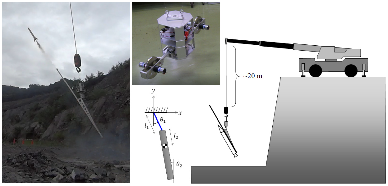
A rail launcher was used to maintain the attitude of the rocket during launch. It was equipped with a CMG device to control the azimuth angle. The launcher was lifted via a crane instead of a balloon because it is easy to control the launch point and altitude. Furthermore, its dynamic behavior can be observed closely from the ground. The drawbacks of using a crane is that the vertical motion is restricted, although an oscillation along the vertical axis is an issue in a high-altitude balloon [
18]. A genuine balloon experiment is necessary in the future study; however, the goals of this study can be achieved even in the crane experiment.
The attitude controller of the launcher is necessary to maintain the target direction of the rail against disturbances caused by wind and balloon motion. With respect to elevation angle, there exists an equilibrium point at which the CG of the launcher, combined with the rocket, is on the extension line of the suspending wire. However, the azimuth angle should be actively controlled until the rocket clears the launcher because there is no equilibrium point in the azimuthal direction. Even if the launcher attitude is accurately controlled before ignition, as the rocket moves on the rail after ignition, the launcher attitude changes due to the frictional force at the sliding point and movement of the position of the CG. It is difficult to actively control the launcher attitude during this period because it is as short as 0.5 s. Such behavior should be predicted and considered when the target angles are determined before launch.
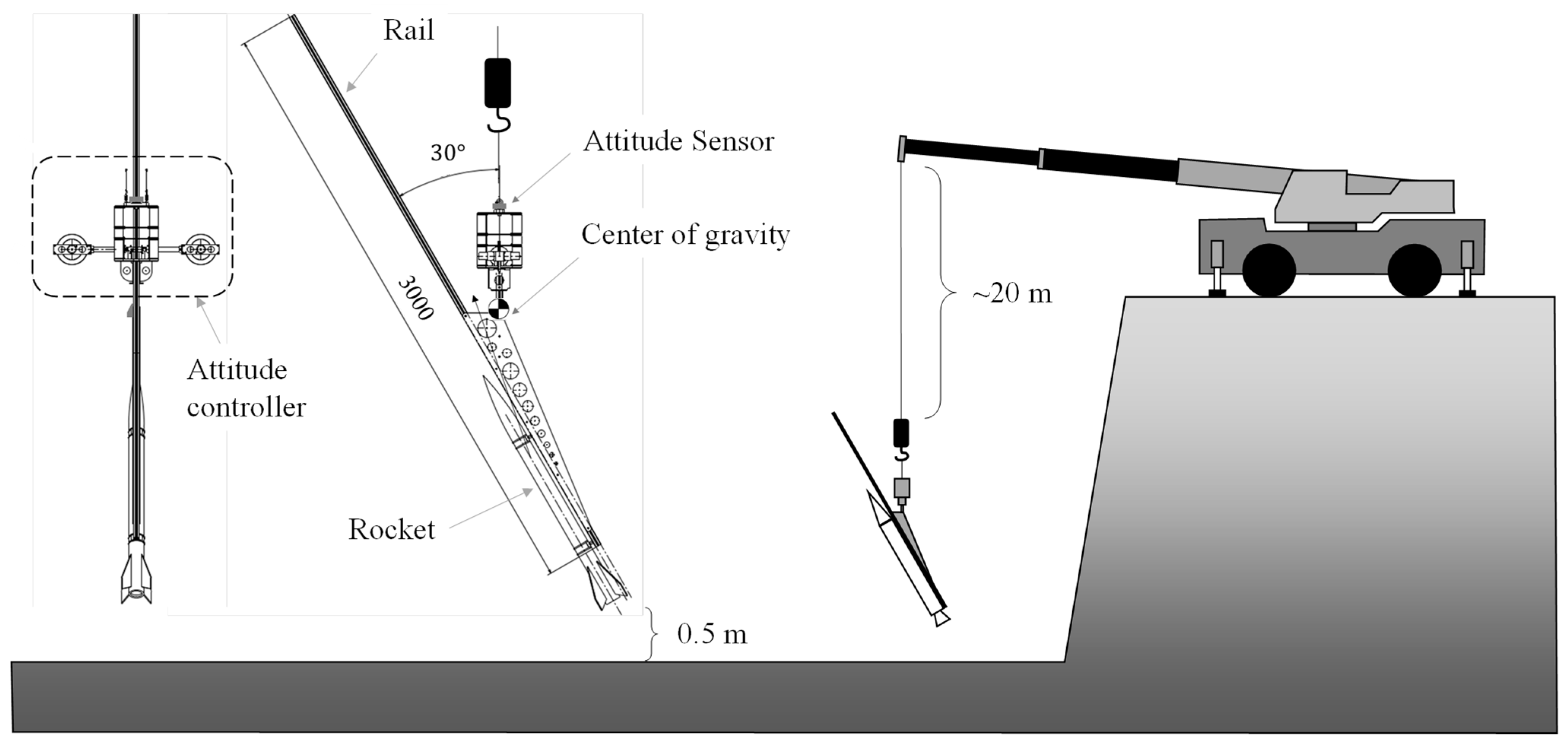
A small rail launcher, shown in
Figure 1, was constructed to study the dynamic behavior during an actual launch. It was equipped with a CMG to control the azimuth angle of the launcher. The attitude of the launcher was recorded using an accelerometer mounted on top of the attitude controller.
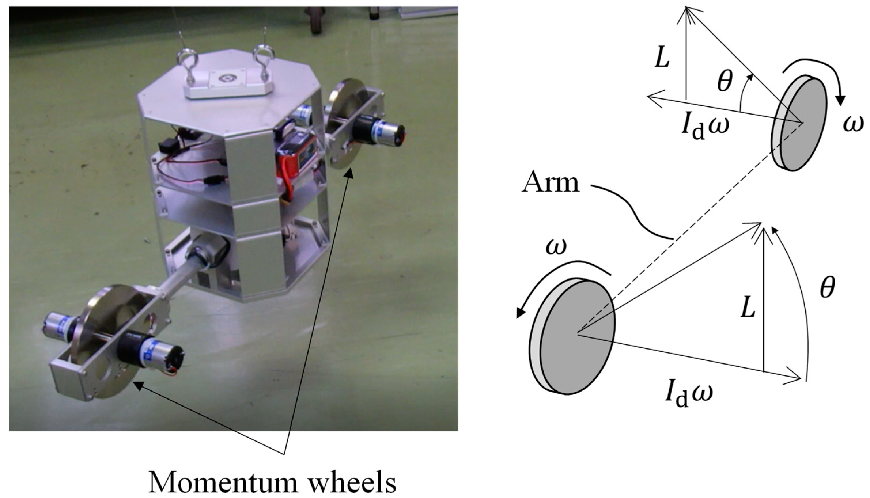
Figure 2 shows the details of the attitude controller structure. It comprises a pair of momentum wheels driven at the same angular velocity
by electric motors located on both sides of the horizontal arms. The rotating axis is tilted by
around the horizontal arm. A hobby servo motor and radio controller were used to enable remote-controlled operation. They were powered by a lithium polymer battery. Because the wheels were rotating in opposite directions to each other, the tilting direction was opposite to produce an azimuthal torque, as shown in
Figure 2. If the rotational direction of the wheels is the same, the tilting angle should be the same. However, this type of motion generates a repulsive torque with respect to the horizontal arm, thereby leading to an unstable oscillation in the elevation angle. As the rotational speed of the wheels increases with angular momentum, the reaction torque obtained by tilting the rotation axes increases.
The dimensions and rotational speed of CMG were determined as follows. To calculate the generated torque, the initial state depicted in
Figure 2 is considered. Suppose that both wheel axes are horizontal and rotated in opposite directions at the same angular velocity
. The angular momentum of the wheel is
, where
denotes the moment of inertia of the rotor assembly. When the rotor axes are tilted by
, the angular momentum of each wheel changes by
in the vertical upward direction and by
in the horizontal direction. Thus, the total momentum in the vertical direction increases by
while the change in the horizontal direction cancels out with each wheel. As a reaction, the launcher obtains the vertical downward angular momentum as follows:
When the launcher has a moment of inertia
about the vertical axis, it starts clockwise rotation, when viewed from the above, at an angular velocity of
If it rotates before tilting, the rotation speed changes by
. When the launcher is oriented toward the target azimuth, the tilted angle should revert to the original state to stop the rotation.
Supplemental Video S1 shows this behavior. When it receives a unidirectional disturbance torque from the wind, it is necessary to continuously produce a canceling torque
. When the tilting angle rate is
, the azimuthal torque generated by the CMG is obtained by differentiating Equation (1), as follows:
The tilting angle rate must be applied continuously to cancel the steady azimuthal disturbance torque. When the tilting angle reaches , the azimuthal torque vanishes and the rotational speed of the launcher cannot be changed further; this is CMG saturation. In this study, the specifications were determined as , , and . Then, the maximum rotational speed at saturation is , which seems sufficient for attitude control. To increase the torque , the wheel should be rotated as quickly as possible. The generation of the azimuthal torque is possible even when by changing the wheel speed at a rate . However, the generated torque was quite low and the duration required to maintain the torque was short because holds.
The launcher was not equipped with an active control function for the elevation angle. The launcher rail was fixed to an azimuthal attitude controller. The elevation angle fluctuates around the equilibrium point. After the launch, the CG changes with the attitude in equilibrium and oscillates about the equilibrium, similar to a pendulum. This behavior is discussed in detail later in this paper.
4. Discussion
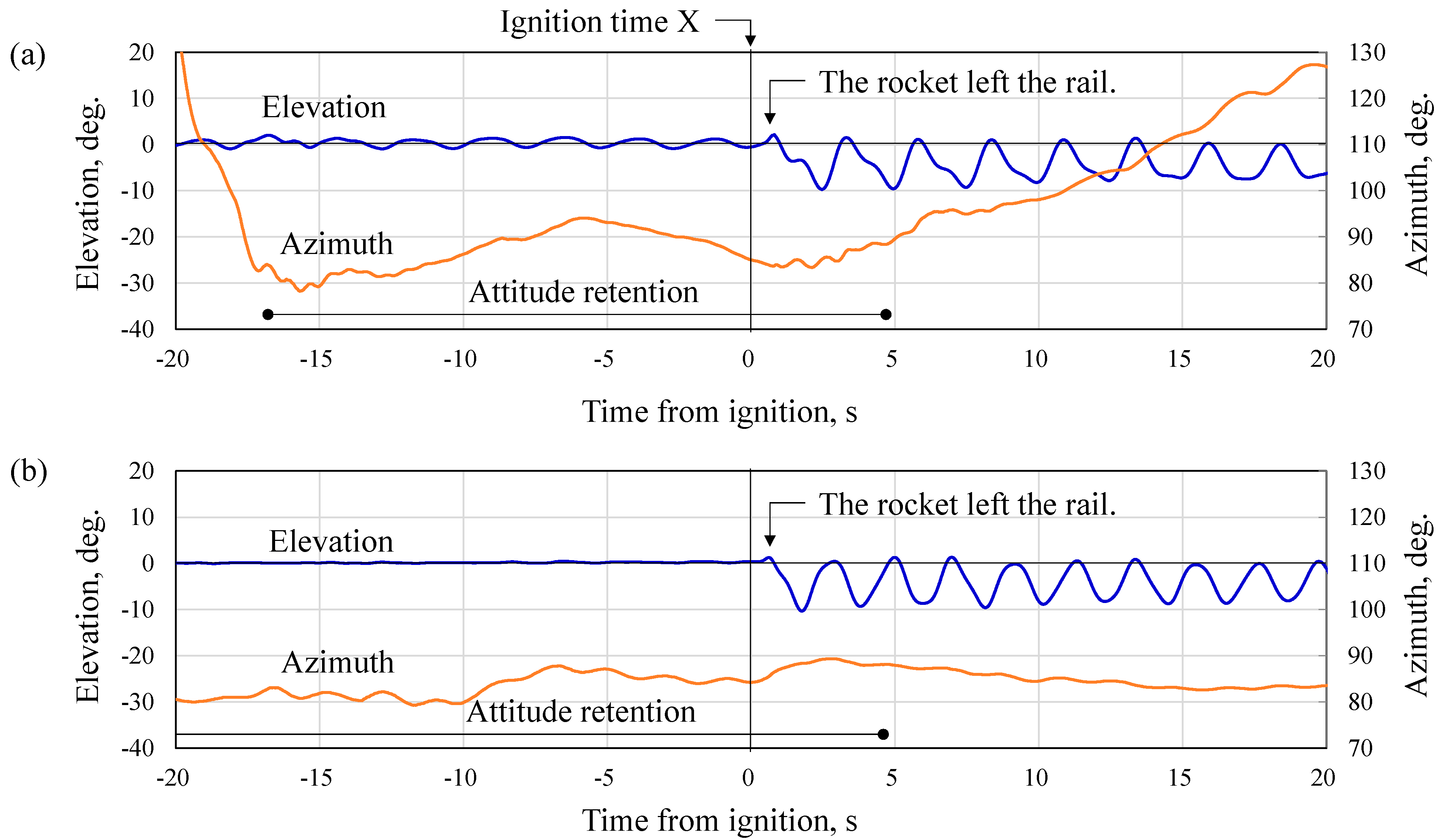
The experimental results exhibited an increase in the actual elevation angle when the rocket reached the end of the launcher rail. This behavior changes the actual elevation angle and significantly affects the trajectory accuracy and range safety; therefore, detailed discussions on these pendulum dynamics are necessary to predict the change in elevation angle. Although a complete dynamic model of balloon-borne systems was proposed by Kassarian [
16], relative motions and separations of an internal object cannot be considered. In this section, a pendulum model is proposed for a suspended launcher with a launch object. The dynamics after the rocket has left the launcher seems to be of little importance because it does not affect the launch trajectory. However, the detailed discussion is necessary to validate the model and to show the reader how to identify the model parameters.
4.1. Double Pendulum Model
To obtain a dynamical model of the suspended launcher, we focused on the non-sinusoidal oscillation of the elevation angle, which was observed after ignition. Because these behaviors were similar in both launches in
Figure 4, only the first launch is considered in the following discussions.
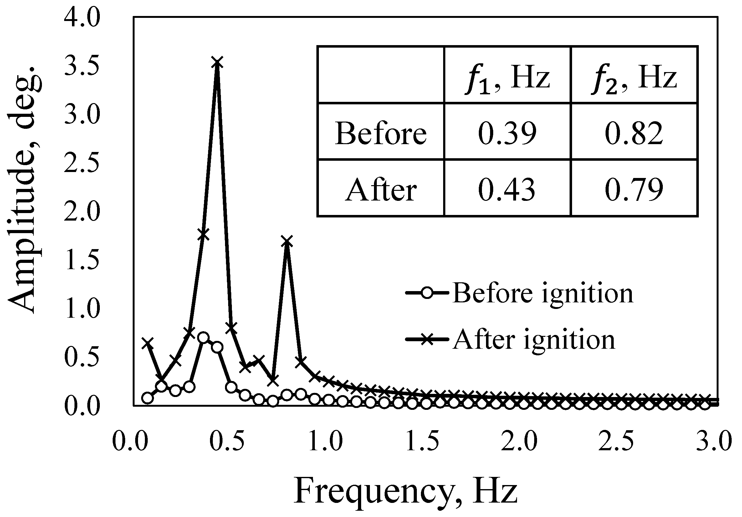
Figure 5 shows the results of the fast Fourier transformation (FFT) of the elevation angle for the two 14-second time series before ignition (X − 15.3 s–X − 1.3 s) and after ignition (X + 0.5 s–X + 14.5 s). In both cases, two components of frequency
and
were observed. The frequency of the lower component,
, increased after the ignition because the CG moved upward owing to the absence of the rocket, reducing the length of the pendulum. However, the frequency of the other component,
, decreased.
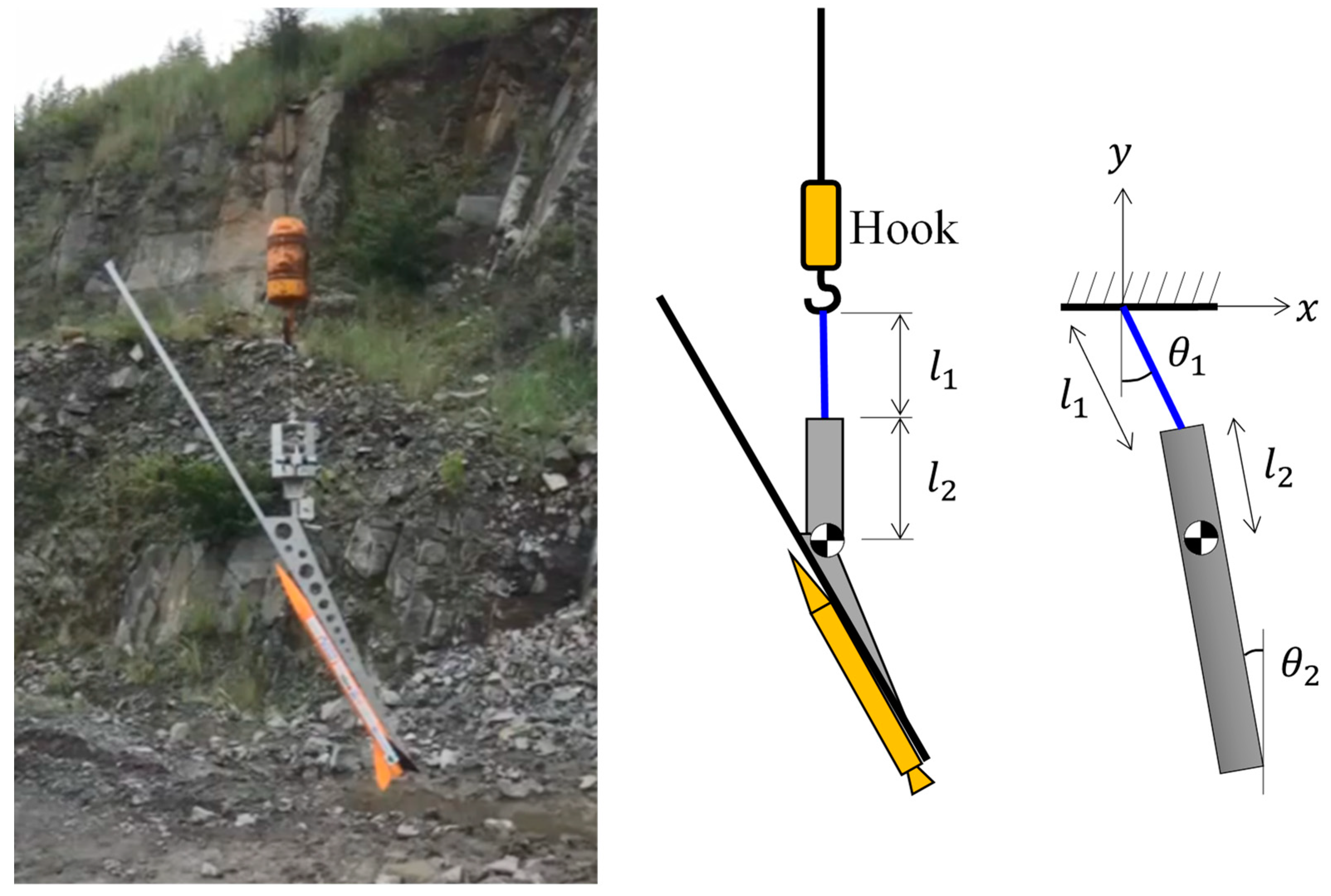
To present a quantitative explanation of this behavior, the suspended launcher is represented as a double pendulum model, as shown in
Figure 6. A rigid rod was suspended using a weightless wire with a rigid support. The mass, CG, and moment of inertia of the rod were the same as those of the launcher assembly. The wire connecting the launcher and hook has length
. The hook moves slightly in the horizontal direction; however, the hook is assumed to be a rigid support because of its significantly higher mass (60 kg) compared to the launcher assembly. This was further confirmed by the fact that the hook was almost stationary for several seconds after ignition (see
Supplemental Video S2).
The eigenfrequencies of this model are obtained by solving Euler–Lagrange equations for the attitude angles.
The Lagrangian is defined as
. The total kinetic energy comprises two terms of the translational motion of CG and the rotational motion around CG.
Here the following approximations for small amplitudes of angles were used.
The potential energy of CG is expressed as follows.
Here the approximations of Equation (6) were used again, and a constant term was eliminated because the origin of potential energy is arbitral. Thus, Lagrangian is expressed as a function of angles and angular velocities.
Substituting Equation (8) to Equation (4), we obtain two motion equations.
Now periodic solutions for the angles are assumed.
Substituting Equation (11) to Equations (9) and (10), we have a matrix equation.
There is a non-trivial solution if and only if the determinant of the matrix is zero.
There are two solutions for
. We take only positive roots for
.
The solutions
are the 1st and 2nd mode frequencies (
. The mode shape parameter is obtained by substituting Equation (14) to Equation (12).
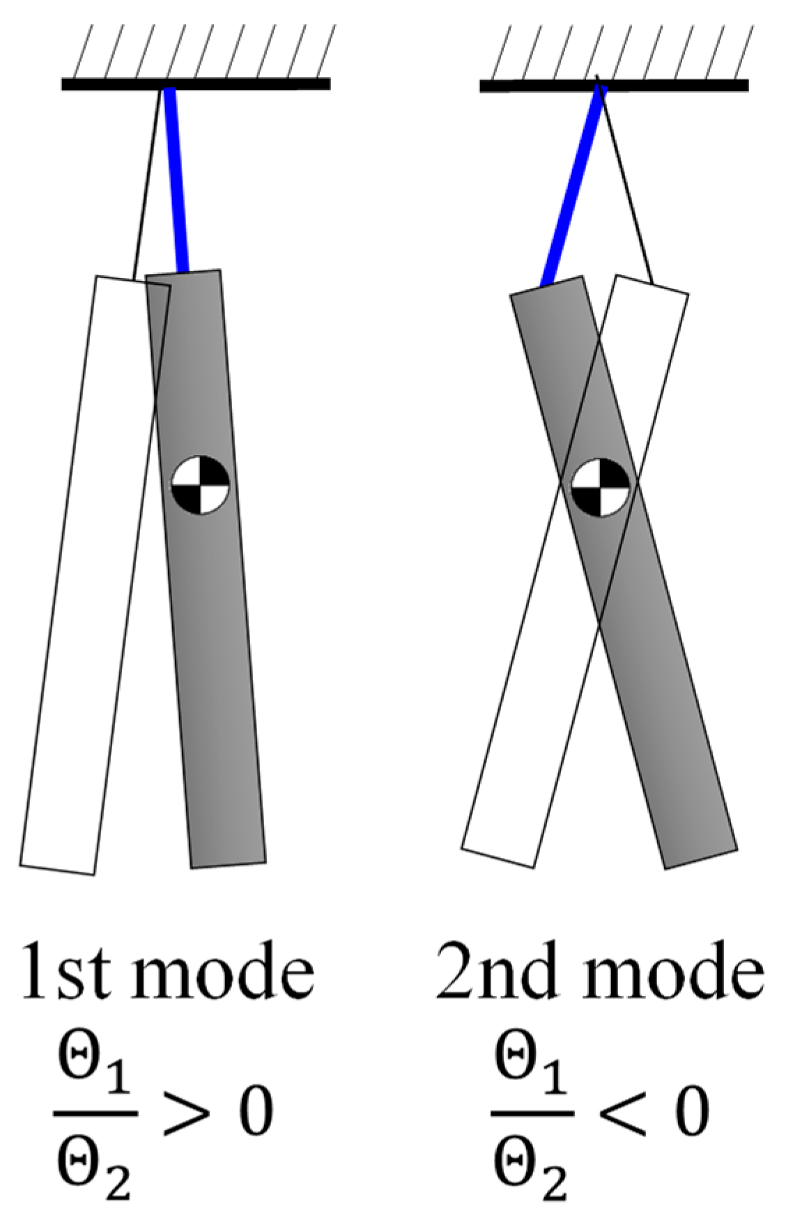
The eigenfrequencies and mode shape parameter are calculated by using the actual values of structural properties as listed in
Table 1. The mode shape parameters are positive for 1st mode and negative for 2nd mode. Hence, the mode shapes are as depicted in
Figure 7. Theoretical 1st mode frequencies agreed with the experimental values presented in
Figure 5, whereas those of 2nd mode frequencies are higher than the experimental values with 40% errors. However, they exhibit the same tendency that the 1st mode frequency increases and the 2nd mode frequency decreases after ignition. The eigenfrequencies were better matched with the experimental values by changing the parameters
as presented in
Table 1. The adjusted
are larger than the actual values; this is because this model neglects the lateral motion of the crane hook suspended by the long wire. Actually, the crane hook moves slightly in the horizontal direction. The presence of a large mass above the launcher has a constraining effect on the pendulum motion.
The pendulum model can be improved without changing the parameters by adding another degree of freedom, i.e., crane hook and wire; however, a double pendulum model is used below because it is sufficient to represent the launcher’s behavior in the experiment that only two frequency components are observed.
4.2. Elevation Angle Dynamics
The dynamics of the elevation angle were studied by considering a moving rocket with the pendulum model obtained above. First, the rocket was located at the bottom end of the launcher. After ignition, the CG and inertia moment change as the rocket moves on the rail. Considering the motion of the CG and the contact forces between the rocket and launcher, the equations of motion were solved.
As shown in
Figure 8, a rail is fixed on a rigid rod with a target elevation angle
. Fluctuation angle
is defined as
at the equilibrium state with the rocket on the launcher. When the rod is tilted with
, the actual elevation angle is
from the horizontal. The inertia properties of the rail are included in the rigid rod. Gravitational forces are considered for each CG of the launcher and rocket. A thrust force was applied at the tail of the rocket with a misalignment angle
. While the rocket with mass
and inertia moment
moves on the rail, two contact forces are considered between the rail guides and the rail, a tangential friction force
and a normal force
. The rocket has front and rear rail guides. Because CG of the rocket is located nearby the front rail guide, the friction force was assumed to act only on this guide. The rocket is assumed to move on the rail at a uniform acceleration
as follows:
The vertical motion of the CG of the launcher was neglected. The horizontal motion follows the equation of motion:
The last term is the contribution of the tension force
of the wire, expressed as:
The friction force is calculated if a friction coefficient
was given:
The launcher and rocket rotate around their combined center of gravity (CCG), which varies as the rocket moves on the rail. The combined moment of inertia
around the CCG also varies over time. The external forces are tension
, gravitational forces acting on the launcher and rocket
and thrust
, which has a misalignment
. The friction forces are internal forces that cancel out in the rotational motion of the combined body. Additionally, D’Alembert’s inertial force
is considered at the CG of the rocket with the magnitude expressed by Equation (16). The aerodynamic drag force was neglected because the velocity was low during rocket sliding on the rail. The rotational equation of motion is expressed with the external torque terms generated by these forces as follows:
where
,
, and
are the horizontal locations of the CG of the launcher, rocket, and their combination, respectively.
and
are the relative location vectors from CCG, of the front rail guide, engine nozzle, and CG of the rocket, respectively. All of these location parameters vary with time.
in Equation (20) is obtained from the following geometrical relation:
The horizontal location of the CG of the launcher x is obtained by solving Equation (17).
The friction coefficient
was obtained using the launcher and rocket used in the launch experiments. The launcher was prepared with the rocket on it in the same manner as in the launch experiments. The sliding surface of the rail was cleaned with a solvent before the silicone lubricant was sprayed on it. The launcher rail was tilted down to a negative elevation angle
, until the rocket started sliding on the rail due to gravity. Then, the static friction coefficient was obtained as
. The kinetic friction coefficient was obtained using the same equation, where
is the smallest value at which the sliding rocket continues to slide without stopping. As a result, we obtained static
and kinematic
. The latter value was used in Equation (19) because the rocket is sliding on the rail.
The thrust force was assumed to have a constant value of 60 N, which was obtained from the ascending motion of the rocket recorded in
supplemental Video S1. The unknown thrust misalignment angle was varied to investigate its effect on the launcher dynamics.
Figure 9 shows the calculated fluctuation angle of the launcher
and its rate
compared with the experimental results, where the misalignment angle
was selected for the best agreement. They are almost identical from the ignition time X to X + 1.3 s, that is, 1.0 s after the rocket has left the launcher tip. Furthermore, the following double pendulum motions also have the same frequency and phase, demonstrating the accuracy of the proposed model. Although the possible variation of the misalignment angle
is unknown, the assumed value
is reasonable.
4.3. Parameter Study
This model allows us to study the parameters that have a significant effect on the actual elevation angle behavior at launch. Among others, thrust misalignment, length of the launcher rail, and friction coefficient are considered here.
The thrust misalignment angle was assumed to be downward on the vertical plane, whereas the actual direction was arbitrary around the vehicle axis. A misalignment force in a horizontal plane causes a fluctuation in the azimuth angle, by which the trajectory and impact point turn around a vertical axis. A fluctuation in the elevation angle significantly changes the trajectory, apogee altitude, and downrange of the impact point.
Figure 10 shows the fluctuation of the elevation angle for different angles of thrust misalignment,
. The differences when the rocket leaves the rail are
and
/s. These variations significantly affect the launch trajectory. For example, a 5 ° difference in elevation angle results in a 26 km difference in the apogee altitude and a 100 km difference in the downrange of the impact points in the case of a single-stage suborbital mission with an apogee altitude of 100 km [
17]. Although the effects of elevation angle rate
have not been investigated, they are not negligible.
These variations depend on the time when the rocket leaves the rail, which can be delayed by extending the launcher rail. However, it also has a nose-down effect because the downward torque due to the gravitational force of the rocket increases with the distance between the rocket and CCG. The relation between the rail length and the conditions when the rocket leaves the rail is shown in
Figure 11. The launcher rail has to be long enough to obtain a sufficient velocity when the rocket leaves the rail, which is necessary for the aerodynamic stability of the rocket; however, an excessively long rail results in a large nose-down fluctuation, as shown in this figure. There is another tradeoff between the fluctuations of
and
: for the rail length with
,
has a large fluctuation, and vice versa. The optimum length that minimizes the trajectory
error should be obtained through trajectory analyses with various combinations.
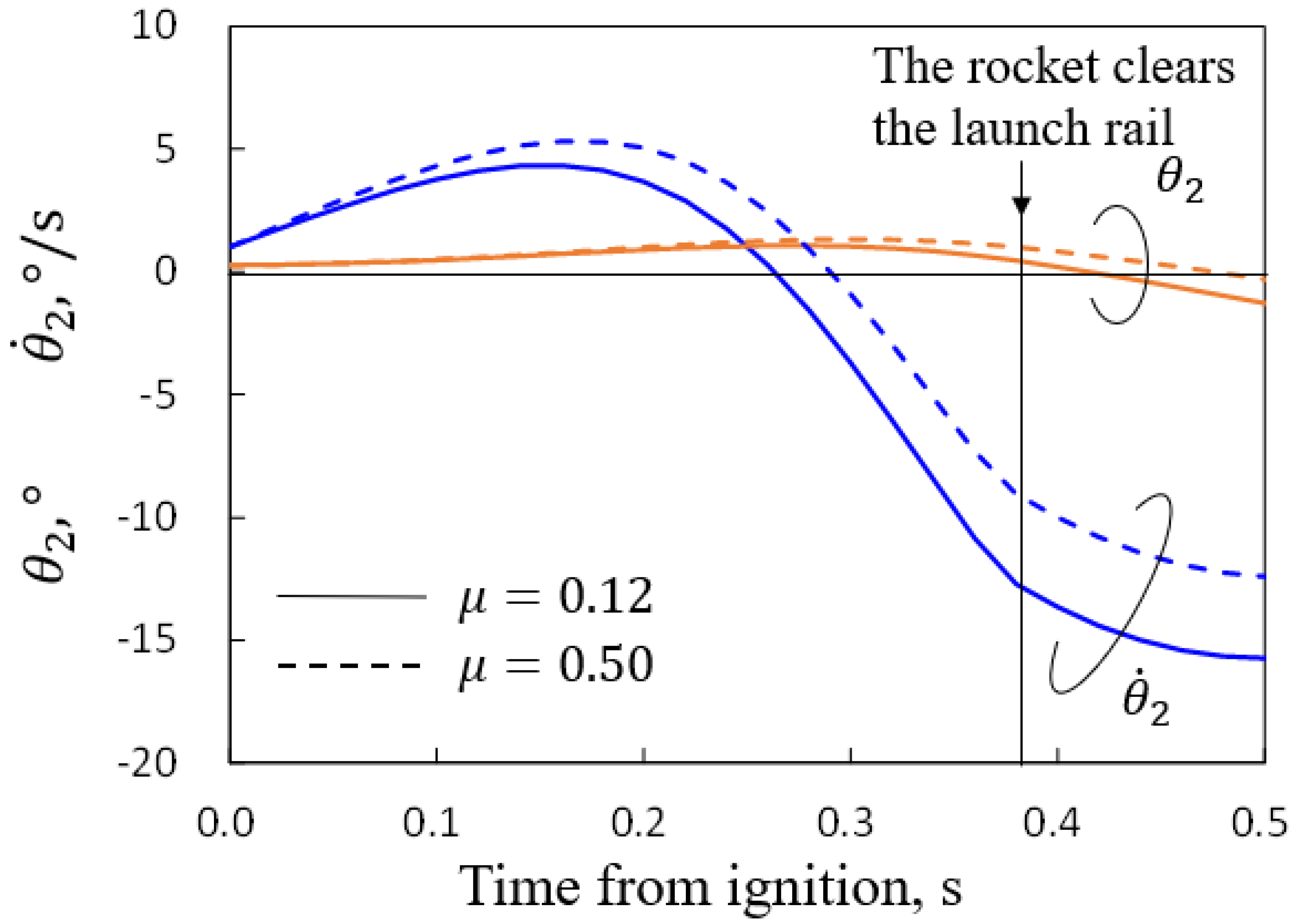
The friction coefficient was obtained in the experiments mentioned above. However, it depends on the tribological conditions between the rail and rail guides on the rocket, such as surface roughness, cleanliness, and lubricant conditions. They could have a large variation depending on the preparation of the launcher and the meteorological conditions. When the silicone lubricant was not applied, the kinetic friction coefficient
increased to 0.17.
Figure 12 shows the elevation fluctuations with the thrust misalignment
comparing the friction coefficients. Considering a possible large value,
for unlubricated steels [
19] was assumed. The increase in
induces a larger nose-up torque during rocket sliding on the rail. The maximum elevation angle was delayed, and the peak value increased by
. As a large value of
causes these increasing variations in the elevation angle, it is necessary to minimize the variation of
by cleaning and lubricating the rail. Although the friction torque can be eliminated by locating the CCG on the rail, the issue of thrust misalignment is more significant.


 ,
, 


