Strain Measurement on Cracks Using Fiber Bragg Gratings for Use in Aircraft Composite Skin Repairs

Physics Department, University of Ioannina, 45110 Ioannina, Greece
Aerospace 2020, 7(9), 138; https://doi.org/10.3390/aerospace7090138
Submission received: 5 July 2020
/
Revised: 18 September 2020
/
Accepted: 21 September 2020
/
Published: 22 September 2020
(This article belongs to the Special Issue Optical and Fiber Optical Sensors for Aerospace Applications)
Abstract
:Fiber Bragg grating (FBG) sensors have been widely used for measurements of strain and temperature in a host of different applications, including aerospace in composite wings, fuselage structures, and other critical components. Here, we report on a method to measure highly localized intense stress fields, generated at the initialization point of a crack, or crack-tip, using Fiber Bragg Gratings (FBG) inscribed in highly photosensitive hydrogenated germanium and boron co-doped fiber. From the spectral characteristics of short and long FBGs, bonded on a test aluminum coupon with a crack, which simulated damaged skins of an aircraft, the local stresses near the cracks were measured and assessed. As a case study, bespoke composite repair patches were designed and bonded on a coupon, incorporating a number of gratings to monitor the stress distribution with applied force in the composite patch, near the crack.
1. Introduction
As metal aircrafts age, fatigue cracks will eventually appear in a number of components, which need to be monitored periodically to ensure safe operation. Depending on the severity and location of the damage, there are a number of ways to monitor their structural health (SHM) by non-distractive testing (NDT) with ultrasonic or x-rays directly on the aircraft or in specialized laboratories [1]. One such example is damage on the aluminum skin of the aircraft that occurs either due to accidents on the ground or fatigue leading to the formation of cracks, requiring replacement of the section with new metal, fastened with rivets or bonded with specialized epoxy resins [2]. With the advent of composite materials, alternative repair protocols can be implemented using composite repair structures or patches, which can be bonded directly on the skin. A big advantage of this method is the seamless distribution of stress on the structure without the highly localized stress fields associated with rivets, low weight, and better durability [3].
Once the damage is located and assessed, a repair protocol is selected which may involve periodic monitoring to ensure that stresses remain within its designed parameters. Stress gauges have been widely used over the years for aluminum-based repairs, but they are not well suited for composite materials due to their size, which prohibits embedment in the composite matrix. In recent years, Fiber Bragg gratings (FBG), inscribed primarily in germane silica fibers, proved to be compatible with composites, primarily due to the small diameter fibers, typically 80 to 125 μm, which facilitates their inclusion in the composite without affecting their structural integrity [2]. As such, FBGs have demonstrated the ability to measure both temperature and strain by incorporating several of them on a single fiber, each centered at different wavelengths, to form a quasi-distributed array of [4]. The optical characteristics of FBGs are determined by their periodicity, refractive index change (Δn), and length, which define, respectively, the operational wavelength, spectral linewidth, and peak reflectivity.
In general, the response of FBGs to applied axial stress or temperature results in a corresponding change to the reflected wavelength without a change in other parameters such as spectral linewidth or reflectivity. However, in the case of non-uniform stress fields, as those applied when FBGs are embedded in composite materials, e.g., undergoing curing, the spectra will change due to residual variations in the applied forces along the active region of the gratings and spectral broadening or splitting can occur [5]. This spectral response, to induced non-uniformities in FBG, can be a useful tool in sensing applications and has been studied extensively by a number of researchers using piezoelectric ceramics [6] or heating a small section of the grating to alter the spectral response [7,8]. For example, if the heated segment is <1% of the grating length, a transmission window in the reflected spectrum could be observed, while if the heated region is more than 20%, a secondary peak at a longer wavelength in the reflectance spectrum is observed [9,10]. If however an FBG is subjected to transverse forces, i.e., is stressed differently in the x and y axes, with z being the propagation axis, it can become birefringent, which results in a spectral peak splitting related to the induced stress in the fiber core [11,12]. Such conditions exist near the tip of the cracks and depending on the length of the grating, its reflectivity, and orientation relative to the stress, the spectra can be broadened [9,13] or even split into separate peaks. This can be attributed to induced birefringence or the generation of a secondary local grating within the original one [10,14].
In this paper, we report on a method to determine the stress fields associated at the tip of a crack using a long and a very short FBG, inscribed on highly photosensitive hydrogenated boron co-doped fiber with high index modulation and reflectivity. Both gratings were bonded on an aluminum coupon and co-located at the tip of a crack. The observed spectral splitting of the long grating with applied force on the coupon gave an accurate measurement of the highly localized stress fields’ neat crack-tip. Furthermore, when the spectra of the short and long FBGs were compared, it transpired that a secondary grating, generated within the long grating, rather than birefringence, was the primary mechanism of this phenomenon. Based on these findings, an aluminum coupon with a crack, simulating a damaged skin of an aircraft, was repair with a composite patch which incorporated FBGs in its matrix and used to assess the performance under stress.
2. Materials and Experimental Setup
2.1. FBG Background
Depending on the applications, the refractive index modulation of an FBG can be constant or apodized and the periodicity of the grating can be constant (linear) or change along its length (chirped grating) [15]. A linear grating with a period Λ = λ0/2 will reflect a specific wavelength λ0, which satisfies the Bragg condition. Its reflectivity and spectral linewidth are dependent on the depth of modulation of the refractive index change (Δn), of the order 10−3 to 10−4, and the number of periods, (grating length), ranging from one to tens of mm [15]. Most standard telecom fibers exhibit some photosensitivity to UV light primarily due to the presence of Germanium doping, required to form the fiber core. However, for fiber sensing applications, photosensitivity can further be enhanced by hydrogen loading prior to inscription, reaching refractive index changes as high as 10−3 [16]. This facilitates the inscription of a long high-reflectivity FBG as well as very short FBGs with grating lengths ranging from 1 to 3 mm capable of measuring a highly localized stress field. In long high-reflectivity FBGs, however, only part of the grating periods is required to fully reflect the guided light at λ0, thus altering its spectral linewidth. As such local strain variations are induced by the embedment of FBGs in composites, they can affect sections of the grating differently, leading to spectral broadening, or birefringence, which can be calibrated to monitor the curing process [17]. This spectral behavior of long high-reflectivity gratings is instrumental in measuring highly localized stress fields, as in the case of crack-tips in a coupon under stress. As will be discussed in more detail in the following sections, the novelty of the method relies on modifying small sections of a uniform grating differently, resulting in spectral splitting, which can be calibrated as a diagnostic tool for crack propagation.
The aims of the work were initially to develop a method for measuring the stresses near the crack-tip of an aluminum coupon which represented a damaged skin section of an aircraft, using a long high sensitivity FBG. To aid calibration, a highly reflective short FBG was also positioned in close proximity to the long grating to gage the stress penetration in the affected region. A second aim was to apply the results to design a bespoke composite repair patch and, with a number of FBGs embedded in its matrix, to measure its performance under stress. To achieve this, we enhanced the photosensitivity of enriched germanium/boron fibers by hydrogen loading and inscribed short, long, and multiple high-reflectivity gratings, as outlined below.
2.2. Inscription of High-Reflectivity FBG
The inscriptions of gratings use primarily interferometric techniques on different photosensitive fibers, which usually have higher germanium concentration in the core [15,18]. Fiber photosensitivity can be determined by the change in the refractive index and calculated using the Bragg condition given as
where λ0 and λ1 are the initial and final inscription wavelengths and Λ is the grating period. In an older work, we used telecom SM fibers, with 5% and special 20% germanium and germanium-boron co-doped fibers (Ge-Bo), with and without hydrogen loading to benchmark their photosensitivity by inscribing and testing a number of different FBGs [19]. It was established that the high germanium and boron co-doped fibers (20% Ge) had the highest photosensitivity, producing grating with peak refractive index modulation Δn of about 3.5 × 10⁻³. The equivalent low Ge (5%) hydrogen loaded fibers had a Δn of about 2.5 × 10⁻⁴, an order of magnitude lower. In this work, we used the same protocols with hydrogen-loading and high concentration Ge with boron co-doped fibers (Hydro-Ge-Bo), to inscribe single and multiple high-reflectivity FBGs, and used them to investigate the stress fields in the coupons.
For the inception of gratings, a Krypton Fluoride (KrF) Excimer laser (Lambda Physik, Göttingen, Germany) was employed, emitting a rectangular beam (35 by 13 mm) at a wavelength of 248 nm. The beam was focused along the fiber axis by cylindrical lens, with a focal length of 20 cm on 25 mm long phase masks, delivering about 100 mJ/cm2 per pulse on the fiber. A variable length rectangular aperture, positioned above the phase mask, adjusted the exposed length of the fiber and hence, the gratings lengths, as shown schematically in Figure 1. Furthermore, the inscription process was monitored in real time by coupling light to the grating, via a fiber optic coupler, from a broadband source and using and the reflected spectra, measured with an Optical Spectrum Analyzer (OSA), as shown in Figure 1. Using this setup, various bespoke single and multiple high-reflectivity FBGs were made and characterized.
The high photosensitivity of the hydro-Ge-Bo fiber enabled the inscription of multiple FBGs with different periods using the experimental setup shown in Figure 1. The inscription protocol involved multiple exposures of small sections of the fiber, selected by reducing the size of the aperture above the phase mask to about 1 to 3 mm. To inscribe several FBGs with the same phase mask, the period on the fiber was changed by applying a constant tension on the fiber during the illumination phase, which, when released, gave different periodicities and hence, gratings. Thus, by altering the position of the aperture on the phase mask fiber assembly and the tension during each exposure, at least five different gratings could be realized, within the length of a 25 mm phase mask, separated by 1.0 to 3 mm from each another and peak wavelength 1 to 1.5 nm from each other. Typically, for high germanium concentration hydro-boron fiber, which was hydrogenated for 90 days in a 170 atmosphere chamber, a 3 mm grating could achieve a maximum reflectivity, without inducing additional spectral broadening of about 94%, while for the 25 mm, it is from 98% to 99%.
2.3. Measurements of Stress in Aluminum Coupon and Composite Repair Patch
Two groups of experiments were conducted without and with a composted patch to establish the stress fields of the “cracked” coupon and subsequently, to assess the performance of the composite repair. Without the composite patch, the intense stress fields present near the crack-tip altered the spectral characteristics of a long grating, producing a secondary peak which could be calibrated to obtain accurate information of the stressing process. With the composite repair patch bonded on an aluminum coupon and embedded short, long, and multiple high-reflectivity FBGs located near the edge of the coupon, the stress performance of the repair patch was assessed.
2.3.1. Aluminum Coupon without Composite Repair Patch
The first part of this work focused on measuring the stress near a slot cut at the center of an aluminum coupon, which represented a crack, by bonding high-reflectivity FBGs close to the crack-tip, as shown schematically in Figure 2. The deletions of the coupon were 30 cm long by 8 cm wide and 5 mm thickness, and the slot was 25 mm long and 1 mm wide. Specifically, a short and a long FBG, with respective wavelengths of 1529 and 1548 nm and grating lengths of 2 and 25 mm, were bonded perpendicularly to the crack at a distance of 1 mm from the crack-tip and within 1 mm of each other, as shown in Figure 2. The initial spectral linewidth of the short and long FBGs were 0.31 and 0.192 nm with peak relativities of 70% and 97%, respectively. The coupon surface was chemically etched to provide good adhesion and the FBGs were attached to the coupon with two-part epoxy resin (Loctite 253 ND), which provided strong bonding. Both FBGs were accurately positioned so the crack-tip was in the midpoint of the gratings and were completely immersed in the two-part epoxy glue, which covered 60 mm on either side of the crack. With this arrangement, the short grating measured only the point stresses at the crack-tip, while the long FBG measured both the average stresses of the coupon under tension as well as the stresses near the crack-tip, as will be discussed in more detail in the following section. To ensure the structural integrity of the FBG after the inscription process, they were protected with a UV cured coating, applied immediately after the laser exposure of the grating. Spatial attention was required in the ingress points to avoid fiber breakage during the testing phase. The aluminum coupon with attached FBGs was subsequently placed in a hydraulic tensioner and subjected to forces 0 to 25 kN, which was well within its elastic limits of the FBGs. Light from Broadband Sources (BBS), emitting at wavelengths ranging from 1510 to 1590 nm, was coupled via a 3 dB fiber coupler to the FBG with the reflected signal transmitted back to an Optical Spectrum Analyzer (OSA), which had a spectral resolution of 0.05 nm, as shown in Figure 2.
2.3.2. Aluminum Coupon with Composite Repair Patch
The composite patch comprised of a six-layer 0°–90° boron prepreg matrix, covering about 65% of the total area of the aluminum coupon. The laminates at both ends were staggered to reduce the likelihood of delamination under stress. To investigate the stress characteristics of the aluminum coupon with the bonded patch under load, FBGs were embedded in between the third and fourth plies. Specifically, short (2 mm) and long (25 mm) FBGs were embedded centrally over the crack, 2.5 and 3 mm from the edge of the patch, respectively, indicated as a and b in Figure 3. Furthermore, a multiple fiber array grating consisting of an array of five short FBGs, each 1.2 mm long, with separation of 2.5 mm from each other, was also embedded in the composite, about 3.5 mm from the edge of the patch, shown as c in Figure 3. It should be noted that the inscription of such short multiple FBGs, with a combined length of 16 mm, was only made possible by the use of the very photosensitive hydro-boron fiber and protocol, shown in Figure 1 and in [19]. The choice of the FBGs locations was determined by stress analysis, which determined that the maximum force exerted on the composite patch was at the outer section of the coupon above the crack. For this reason, the gratings were positioned over the crack with FBG a, b, and c located above the crack, as shown in Figure 3. With this arrangement, all the FBGs were subjected to the same stress distributions in the composite, measuring the variations in the peak wavelengths and spectral broadening as a function of applied stress on the coupon/patch assembly. The use of the close short multiple grating could determine the distinct point stresses of the surrounding region near and above the crack, which is very useful in assessing the effectiveness of the repair.
3. Results and Discussion
3.1. Aluminum Coupon Stress Measurements near the Tip of the Crack
3.1.1. Stress Measurements with Short FBG
To determining the induced stresses at the crack-tip, the aluminum coupon with the bonded short (2 mm) and the long (25 mm) FBGs was subjected to applied forces and their spectra were measured. The central wavelength at 20 °C was 1530.1 and 1548.5 nm (at 20 °C), respectively, and the coupon was placed in a computer controlled hydraulic pulling-jig, which applied tension ranging from 0 to 24 kN. The FBGs were connected to the BBS and via a fiber coupler, connected to the OSA, while the coupon was placed in the pulling jig and clamped at the outer edges, as shown in Figure 2. The force was applied gradually in steps of 0.2 kN, resulting in an extension of 0.01 mm/min. The spectral variations for the 2 mm gratings are shown in Figure 4a, showing the reflection peak gradually moving to longer wavelengths with increasing force. The changes in the wavelength peaks with applied force are shown in Figure 4b and indicate a linear response with a slope of 0.128 nm/kN, indicating that in the vicinity of the crack-tip and within 2 mm of this grating, the stress fields were relatively uniform. However, the spectrum exhibits a small but progressive widening of the linewidth, from 0.285 nm, with no applied force, to 0.412 nm when 24 kN. This indicates a strong variation of the stress fields near the crack-tip [20], which extend further in the coupon but cannot be measured accurately using this short FBG. Additionally, spectral ripples, or side-lobes after the main peaks, are also observed, becoming more pronounced above 14 kN, which are related to small phase changes of the periodic structure, attributed to interference effects within the grating [10,21]. However, these spectral artifacts are small due to the small changes in local forces along the length of the 2 mm grating. Therefore, the linear spectral response of the FBG with applied force, as shown in Figure 4b, can measure reasonably well the local stress near the tip of the crack, which can be calculated directly from the peak wavelength shift. The applied stress εz on the fiber can be calculated using the equation
where λ0 is the peak wavelength with no applied force; n0 is the core refractive index of the GeB co-dropped fibers (n0 = 1.4473); νf is Poisson’s ratio of the fiber, given in the literature as (0.16) [13]. The p11 and p12 parameters are the strain optic coefficient with the indices 1 and 2 being the axial (z) and transverse (x) axes of the fiber, given in the literature as 0.113 and 0.252, respectively [13]. Figure 4c shows the local stress of the bonded FBG near the crack-tip, calculated using Equation (2), as a function of applied force on the coupon. The results in Figure 4b,c verify that the applied stress on the 2 mm grating is mostly uniform as there is a small distortion to the spectra with increasing stress. It should be noted, however, that the change in the peak wavelength of 3.89 nm and a change in FWHM of 0.126 nm with applied force shown in Figure 4a, indicate a strong stress gradient in the immediate vicinity the crack, which extends further in the coupon with applied force. However, due to the small size of the FBG, this cannot be seen clearly by the spectral behavior of the short FBG but will be more evident from results of the long grating presented in the following section.
3.1.2. Stress Measurements with Long FBG
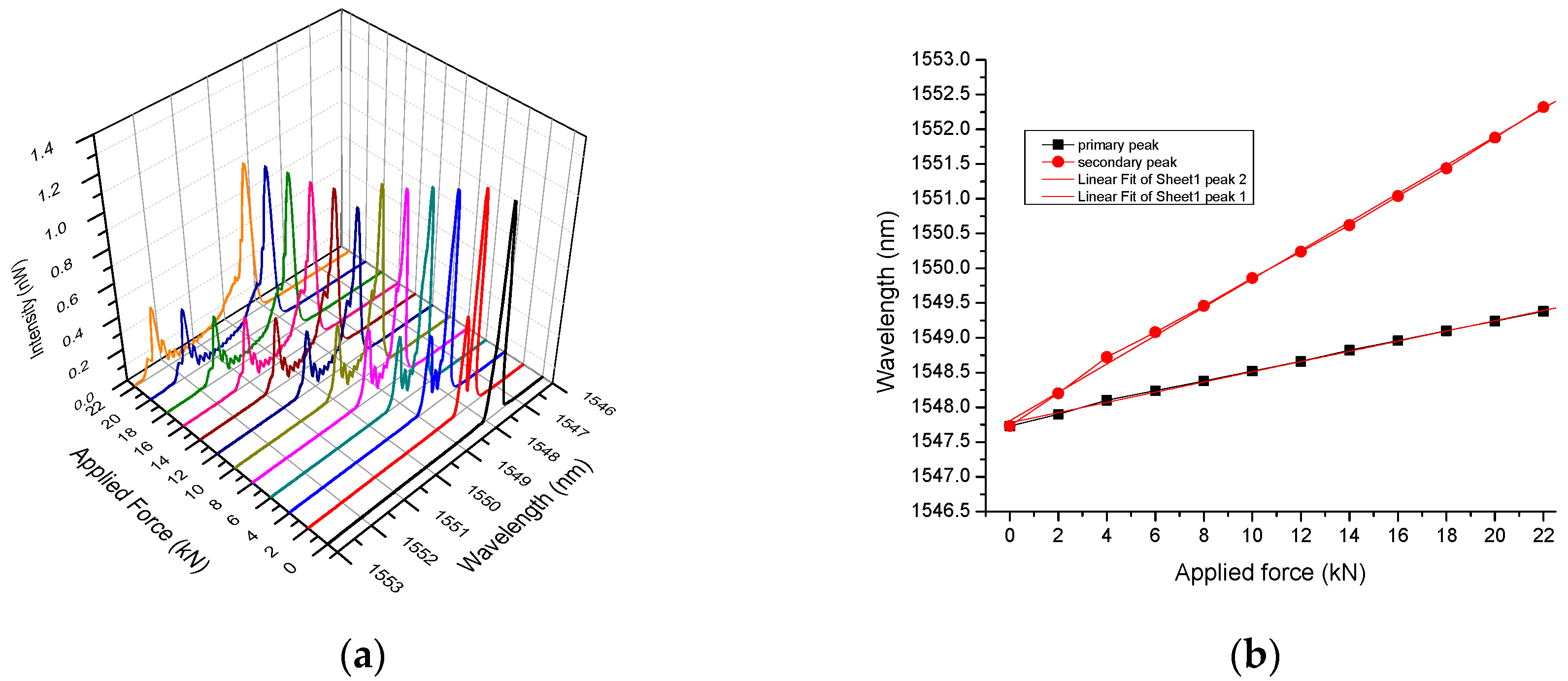
The spectral characteristics of the 25 mm FBG with applied force can be seen in Figure 5a, exhibiting a very different spectral response to the short grating. Specifically, when bonded on the coupon centrally and symmetrically near the crack-tip, the spectral peak without applied stress was measured at 1547 nm with an initial linewidth of 0.192 nm and a reflectivity close to 97%. However, with increasing applied force on the coupon, the initial single peak is gradually split into two distinct peaks, which migrate to longer wavelengths at different rates. The spectral variations of the two peaks with applied force are both linear and are shown in Figure 5b, with the primary peak (shown in black) having a gradient of 0.073 ± 0.001 nm/kN, while the secondary peak (shown in red) has a gradient of 0.204 ± 0.001 nm/kN. Furthermore, a closer examination of the spectra reveals interference fringes in between the two peaks, as shown more clearly in Figure 6a, which, according to the literature, are associated with a Fabry Perot Etalon (FPE) effect [10]. From the Free Spectral Range (FSR) of the interference pattern, we can calculate the cavity length using the standard relation for the FPE:
where n is the fiber core refractive index and λ is the free space reflected wavelength of the grating [18]. The calculated FPE cavity length L as a function of applied force on the coupon is shown in Figure 6b.
The spectral behavior of the 25 mm grating could be attributed to either induced birefringence by the intense transverse stress fields near the crack-tip exerted perpendicularly to the propagation axis of the fiber [21] or the generation of a second local sub grating near the crack-tip [22]. Birefringence was first observed by Guemes and Menendez [23] by applying a uniform transverse force along the length of a 5 mm FBG, generating a dual peak which separated with increasing transverse force, giving similar results to those shown in Figure 5b. However, in contrast with our work, (a) their spectra did not exhibit interference patterns, (b) their gratings were five times smaller than ours (5 mm), and (c) the transverse force was applied uniformly along the length of the FBG. Furthermore, our short grating (2 mm), which was co-located with the long grating (25 mm) and hence, subjected to the same transverse forces, did not show any spectral splitting. This indicates that induced birefringence was not the dominant mechanism for the observed spectral splitting of the long grating.
The alternative mechanism suggested above relies on the way forces are distributed near the crack, which is located centrally on the grating, and affects differentially the local periods along the length of the FBG. Specifically, based on crack propagation models, the stress fields near the crack-tip have a very sharp spatial stress distribution, which is increasing and decreasing rapidly in the vicinity of the crack-tip [20,24]. These stress distributions increase in intensity and expand further with rising applied force on the coupon, affecting more periods of the grating. However, at greater distances from the crack, the stress fields are uniform, similar to those in the rest of the coupon. Therefore, the central section of the grating is affected by the high intensity stresses present near the crack-tip, while the outer sections further away measure the residual stress of the coupon. Thus, the grating is effectively split roughly into two regions, with the two outer sections located in the low stress areas of the coupon symmetrically either side of the crack, generating the primary peak. Similarly, the central section is affected by the high stresses near the crack-tip and generates the second peak, as shown in Figure 5a. Furthermore, the two regions are in dynamic equilibrium, with the central region expanding while the outer regions are reducing with applied force.
This mechanism has two important implications for the spectral behavior of the grating, namely the effective length of the cavity of the FPE and the spectral linewidth of the two peaks. Specifically, the FPE cavity is formed between the two outer sections of the FBG which act as “mirrors”, reflecting at the wavelength of the primary peak. The cavity length is directly dependent on the length the secondary grating in the central section of the grating as it reflects at the wavelength of the secondary peak. As the stresses near and further away from the crack change with increasing applied force on the coupon, so do the affected regions of the grating, resulting in a dynamic equilibrium of the outer and inner periods. Subsequently, this will directly affect the evolution of dual “nested” gratings by altering FPE cavity length, as the stresses near the crack-tip alter the number of the central periods, effectively increasing the cavity of the FPE, and inadvertently decreasing the length of the “mirrors”. Using the FSR from the spectra in Figure 5a and Figure 6a, the cavity length L can be calculated using Equation (3). The results show that the effective cavity length L increases with applied force on the coupon, reaching a maximum of about 6.4 mm at 20 kN, as shown in Figure 6b. This mechanism can account for the observed spectral interference patterns shown in Figure 6a, also reported by Torres [10], who obtained similar FPE interference fringes, by applying transverse forces in a small central section of a long FBG. This is an important result as it can measure, perhaps uniquely, high stress regions near the crack.
Another important aspect of this mechanism is that as the lengths of the “nested” gratings alter, it directly changes the spectral linewidth of the primary and secondary peaks. This can be observed in the spectra shown in Figure 5a, which show that with increasing applied force on the coupon, there was an increase to the spectral FWHM of the primary peak, with a corresponding decrease to the FWHM of the secondary peak. Therefore, as the spectrum of a grating is directly related to the number of periods and those of the central section increase with applied force, the Full Width Half Maximum (FWHM) of the secondary peak is reduced. Conversely, the number of the outer periods of the grating forming the two “mirrors” of the FPE reduces, resulting in the observed increase in the FWHM of the linewidth of the primary peak, as shown in Figure 7a. The measurements of the FWHM for the primary and secondary peaks were obtained by the expanded spectra, as shown in Figure 6a, and for applied forces greater than 4 kN, where overlapping was not an issue.
The spectral behavior of the long FBG can be used directly to investigate highly localized stress areas which are inaccessible by other devices. In this application, it is possible to measure simultaneously the stresses on the coupon, given by the first spectral peak as well as the local stresses at the crack-tip measured by the second peak. These measurements can be used to correlate and quantify locally how the crack is affected in relation to the rest of the coupon using a single long high-reflectivity grating. This method can potentially be applied to the skins or other structural components of aircraft and assist in the design and application of a composite repair patch of the damage areas.
3.2. Aluminum Coupon with Composite Patch over the Crack
As outlined above, the sensitive short, long, and multiple FBGs are well suited to measure the distribution of forces and as a test case, a boron-fiber composite repair patch was bonded on an aluminum coupon covering the crack and about 65% of the coupon area. As described in Section 2.3.2, it consisted of six plies, which included a 2 mm and a 25 mm grating as well as a multiple grating. The gratings were positioned in the high stress region on the composite patch which according to calculations and the literature is near the edge of the coupon. Thus, the FBGs were located 2.5 mm from the edge of the coupon and separated by about 0.5 mm from each other, positioned over the crack in between ply 3 and 4, as shown in Figure 3. By using this geometry, the gratings were subjected to the maximum stress fields, which effectively are shunted from the coupon to the composite patch.
The spectral behaviors of the 2 mm grating with applied force on the coupon are shown in Figure 8a, which shows the variation in wavelength with applied force which varied from 0 to 50 kN.
Furthermore, the spectral linewidth remains unchanged with increasing stress and the peak wavelength changed nearly linearly, as seen in Figure 8b, with a gradient 0.043 ± 0.002 nm/kN. The peak wavelength variations of the 25 mm FBG are shown in Figure 9a,b, which shows the typical transition to longer wavelengths with increasing force having a gradient of 0.031 ± 0.002 nm/kN. However, as can be seen from Figure 9a, the initial linewidth of the embedded FBG has a value of 0.39 nm, much wider than the inscription value of 0.19 nm, which is attributed to curing-induced stresses transferred on the grating. Furthermore, with increasing applied stress on the coupon, the spectral linewidth, expressed as the FWHM of the peaks, increases linearly, reaching a value of 0.95 nm, and having a gradient of 0.009 ± 0.0005 nm/kN (Figure 9c). The variations of the FWHM with applied force, shown in Figure 9c, indicate that (a) the long FBG is firmly embedded in the composite metric, and (b) the forces over the crack are non-uniform altering the grating periods along the length of the FBG, which increase the spectral linewidth. Furthermore, the near linear expansion of the FWHM indicates the forces over the crack are slow-varying, inducing a gradual defamation, or chirp, to the grating with increasing stress, but it is difficult to deduce the exact force distribution over the length of the FBG, solely on linewidth. This information could potentially be measured using Low Coherence interferometry techniques [25], which was not possible due to the noisy environment of the hydraulic pulling gig, but was addressed by the inclusion of the multiple grating array outlined below. When comparing the results of the short and long FBGs in the composite patch, it can be seen that, although both are located in the vicinity relative to the crack, they exhibit very different gradient of 0.043 and 0.031 nm/kN, respectively, due to being subjected to different stress distributions. Compering the results from the two FBGs, the 2 mm grating measures solely the stress fields near the crack, while the 25 mm grating measures the stresses over a larger region of the composite, which is more representative of the average stress values in the composite patch.
To gain better insight into the force distribution in the composite patch, the multiple FBG array was used, as described in the previous section, consisting of five individual 1.2 mm gratings, separated 2.5 mm from each other, having a total combined length of 16 mm, embedded about 3.5 mm from the edge of the coupon (Figure 3). The unstressed spectral linewidth of the five gratings ranged from 0.54 to 0.60 nm. The proximity to the crack and their small lengths facilitate this FBG array to determine more accurately the stress distribution near the crack, not possible with the other two gratings. The fiber grating array was positioned over the crack with the FBG 2 and FBG 3 located closest and above the crack, as shown in Figure 3. The spectral behavior of the five FBGs with applied force is shown in Figure 10a, and the variation of their peak values is shown in Figure 10b. At first glance, the results in Figure 10b show all the peaks shift more or less linearly, with applied force. However, the guardians of the five gratings are not the same, as shown in Figure 10c, which shows the guardian of each of the five FBS with position in mm from the crack, which is located at about 7 mm. Based on Figure 10c, the guardians ranged from 0.034 to 0.028 nm/kN, with FBG 2 and FBG 3 having lower values due to their proximity to the crack. These values seem quite close to the embedded 25 mm grating, which has a value of 0.031 nm/kN, indicating that the composite matrix bridges the force fields evenly over the damaged area. Furthermore, this result is in close agreement with the near linear spectral linewidth FWHM expansion of the long grating shown in Figure 9c, which corroborates the smooth transfer of the forces through the composite. It is also noteworthy that the applied forces on the composite repair patch coupon were taken at 90 kN, a value more than four 4 times that of the aluminum coupon without the patch. Finally, the rather larger gradient (0.043 nm/kN) for the single 2 mm FBG can be attributed to the fact that this grating was located near the edge of the composite patch and is exposed to higher and less uniform stresses.
4. Conclusions
FBGs are very useful tools for measuring stress fields on the surfaces and inside composite components in aerospace applications. In this work, we explored the induced stresses on the surface of an aluminum coupon with a crack by using short and long FBGs, and subsequently, repairing it with a composite patch with embedded FBGs to assess its performance under stress. Using very photosensitive hydrogenated germanium-boron co-doped fibers, it was possible to inscribe 2 and 25 mm high-reflectivity FBGs, and to measure the induced stresses very near the crack-tip, by the spectral variations of the gratings. Both short and long gratings have their individual merits, with the short being capable of measuring accurately local stresses in the immediate vicinity in the crack as well as giving some indication of the uniformity through its spectral distortion, as seen by the results from the aluminum coupon without a patch. Similarly, the highly localized stresses acting on the center of the long grating resulted in splitting the reflection spectrum formatting dual peaks, which shifted to longer wavelengths, at different rates with applied force on the coupon. This was attributed to the modulation of the local grating periods close to the crack, giving rise to the second peak which could be used to measure the local stress near the crack. These attributes enable long gratings to measure accurately the intense stress fields near the crack with the secondary spectral peak, as well the local intrusion in the coupon using the FPE effect generated in the grating structure.
Based on this work, a composite repair patch was bonded on the “cracked” coupon, which incorporated a short and a long FBG together with a multiple grating array, which were used to measure the stress behavior of the coupon near the crack. The gratings were located over the crack and through their spectral characteristics, it was possible to determine the stress distribution of the coupon, which could withstand more than four times the stress of the coupon without the composite patch. The observed increase in the spectral linewidth of the embedded long FBG with applied force was near linear, verifying that the stress distributions were slow varying over the crack. This was also confirmed by the observed spectral variations of the five grating array, which had slow peak transitions with applied force, indicating the forces were redistributed evenly through the composite patch over the damaged area. Finally, these results verify the utility of FBGs in composite matrix and how spectral characteristics can be uniquely employed in the assessment of structural behavior.
Funding
This research received no external funding.
Acknowledgments
ETIDE project/EU ‘‘ELI-LASERLAB Europe Synergy, HiPER & IPERION-CH.gr” (MIS 5002735) and the EU programs “ACIDS” (G4RD-CT-2001-00612). I thank N. Kourkoumelis for useful comments and discussions as well as Z. Marioli-Riga and her team in the Hellenic Aerospace Industry for the use of their facilities and the preparation of coupons.
Conflicts of Interest
The author declares no conflict of interest.
References
- Sekine, H.; Fujimoto, S.; Okabe, T.; Takeda, N.; Yokobori, T., Jr. Structural Health Monitoring of Cracked Aircraft Panels Repaired with Bonded Patches Using Fiber Bragg Grating Sensors. Appl. Compos. Mater. 2006, 13, 87–98. [Google Scholar] [CrossRef]
- Li, H.C.H.; Beck, F.; Dupouy, O.; Herszberg, I.; Stoddart, P.R.; Davis, C.E.; Mouritz, A.P. Strain-based health assessment of bonded composite repairs. Compos. Struct. 2006, 76, 234–242. [Google Scholar] [CrossRef]
- Di Sante, R. Fiber Optic Sensors for Structural Health Monitoring of Aircraft Composite Structures: Recent Advances and Applications. Sensors 2015, 15, 18666–18713. [Google Scholar] [CrossRef] [PubMed]
- García, I.; Zubia, J.; Durana, G.; Aldabaldetreku, G.; Illarramendi, M.A.; Villatoro, J. Optical Fiber Sensors for Aircraft Structural Health Monitoring. Sensors 2015, 15, 15494–15519. [Google Scholar] [CrossRef] [PubMed] [Green Version]
- Kersey, A.D.; Berkoff, T.A.; Morey, W.W. Multiplexed fiber Bragg grating strain-sensor system with a fiber Fabry-Perot wavelength filter. Opt. Lett. 1993, 18, 1370. [Google Scholar] [CrossRef] [PubMed] [Green Version]
- Chehura, E.; Skordos, A.A.; Ye, C.-C.; James, S.W.; Partridge, I.K.; Tatam, R.P. Strain development in curing epoxy resin and glass fiber/epoxy composites monitored by fiber Bragg grating sensors in birefringent optical fiber. Smart Mater. Struct. 2005, 14, 354–362. [Google Scholar] [CrossRef]
- Pacheco, M.; Santoyo, F.M.; Méndez, A.; Zenteno, L.A. Piezoelectric-modulated optical fiber Bragg grating high-voltage sensor. Meas. Sci. Technol. 1999, 10, 9. [Google Scholar] [CrossRef]
- Sandgren, S.; Sahlgren, B.; Asseh, A.; Margulis, W.; Laurell, F.; Stubbe, R.; Lidgard, A. Characterization of Bragg gratings in fibers with heat scan technique. Electron. Lett. 1995, 31, 665. [Google Scholar] [CrossRef]
- Roussel, N.; Magne, S.; Martinez, C.; Ferdinand, P. Measurement of Index Modulation along Fiber Bragg Gratings by Side Scattering and Local Heating Techniques. Opt. Fiber Technol. 1999, 5, 119. [Google Scholar] [CrossRef]
- Torres, P.; Valente, L.C.G. Spectral response of locally pressed fiber Bragg grating. Opt. Commun. 2002, 208, 285–291. [Google Scholar] [CrossRef]
- De Matos, C.J.S.; Torres, P.; Valente, L.C.G.; Margulis, W.; Stubbe, R. Fiber Bragg Grating (FBG) Characterization and Shaping by Local Pressure. J. Lightwave Technol. 2001, 19, 1202–1211. [Google Scholar] [CrossRef]
- Udd, E.; Schulz, W.L.; Seim, J.M.; Trego, A.; Haugse, E.D.; Johnson, P.E. Use of transversely loaded fiber optic Grating strain sensors for aerospace applications. Proc. SPIE 2000, 3994. [Google Scholar] [CrossRef]
- Okabe, Y.; Yashiro, S.; Kosaka, T.; Takeda, N. Detection of transverse cracks in CFRP composites using embedded fiber Bragg grating sensors. Smart Mater. Struct. 2000, 9, 832–838. [Google Scholar] [CrossRef]
- Okabe, Y.; Tsuji, R.; Takeda, N. Application of chirped fiber Bragg grating sensors for identification of crack locations in composites. Compos. Part A 2004, 35, 59–65. [Google Scholar] [CrossRef]
- Udd, E. An Overview of Fiber-Optic Sensors. Rev. Sci. Instrum. 1995, 66, 4015–5030. [Google Scholar] [CrossRef]
- Erdogan, T. Fiber Grating Spectra. J. Lightwave Technol. 1997, 15, 1277–1294. [Google Scholar] [CrossRef] [Green Version]
- Crossley, S.; Margioli-Rega, Z.; Tsamasphyros, G.; Kanderakis, G.; Fournarakis, N.; Ikiades, A.; Kostandaki, M. Small Patches: Self-monitoring composite patches for the repair of aircraft. Proc. SPIE Int. Soc. Opt. Eng. 2004, 5272. [Google Scholar] [CrossRef]
- McKenzie, I.; Jones, R.; Marshall, I.H.; Galea, S. Optical fiber sensors for health monitoring of bonded repair systems. Compos. Struct. 2000, 50, 405–416. [Google Scholar] [CrossRef]
- Konstantaki, M.; Tamiolakis, G.; Argyris, A.; Othonos, A.; Ikiades, A. Effects of Ge concentration, B co-doping and hydrogenation on fiber Bragg grating characteristics. Microw. Opt. Technol. Lett. 2005, 44, 148–152. [Google Scholar] [CrossRef]
- Dong, P.; Zhang, P.; Li, R. Study on stress distribution near crack tip in beryllium compact tension specimen. In Proceedings of the 12th A-PCNDT 2006—Asia-Pacific Conference on NDT, Auckland, New Zealand, 5–10 November 2006. [Google Scholar]
- Studera, M.; Petersb, K.; Botsis, J. Method for determination of crack bridging parameters using long optical fiber Bragg grating sensors. Compos. Part B Eng. 2003, 34, 347–359. [Google Scholar] [CrossRef]
- Zheng, L.L.; Gao, Y.F.; Lee, S.Y.; Barabash, R.I.; Lee, J.H.; Liaw, P.K. Intergranular strain evolution near fatigue crack tips in polycrystalline metals. J. Mech. Phys. Solids 2011, 59, 2307–2322. [Google Scholar] [CrossRef]
- Guemes, J.A.; Menendez, J.M. Response of FBG-optic sensors when embraced in composites laminates. Compos. Sci. Technol. 2002, 62, 959–966. [Google Scholar] [CrossRef]
- Bertholds, A.; Dandliker, R. Determination of strain optic coefficient in Single Mode optical Fibers. J. Lightwave Technol. 1988, 6, 17–20. [Google Scholar] [CrossRef]
- Botsis, J.; Humbert, L.; Colpo, F.; Giaccari, P. Embedded fiber Bragg grating sensor for internal strain measurements in polymeric materials. Opt. Lasers Eng. 2005, 43, 491–510. [Google Scholar] [CrossRef]
Figure 1.
Experimental setup for inscription of Fiber Bragg Gratings.

Figure 2.
Aluminum coupon with short and long FBGs.

Figure 3.
Aluminum coupon with a 6-ply composite patch and short (a), long (b), and multiple (c) FBGs embedded in between ply 3 and 4 over the crack.
Figure 3.
Aluminum coupon with a 6-ply composite patch and short (a), long (b), and multiple (c) FBGs embedded in between ply 3 and 4 over the crack.

Figure 4.
(a) 2 mm FBG spectral response with applied force near the crack-tip without composite patch. (b) Peak spectral response with applied force. (c) Stress on bonded FBG near the crack as a faction of applied force.
Figure 4.
(a) 2 mm FBG spectral response with applied force near the crack-tip without composite patch. (b) Peak spectral response with applied force. (c) Stress on bonded FBG near the crack as a faction of applied force.

Figure 5.
(a) 25 mm FBG spectral response with applied force near the crack-tip without composite patch. (b) Spectral variations of the FBG maximum intensities of the primary and secondary reflected peaks of with applied force.
Figure 5.
(a) 25 mm FBG spectral response with applied force near the crack-tip without composite patch. (b) Spectral variations of the FBG maximum intensities of the primary and secondary reflected peaks of with applied force.

Figure 6.
(a) Three distinct peaks spectral response with applied force of the 25 mm FBG. (b) FPE effective cavity length in mm with applied force.
Figure 6.
(a) Three distinct peaks spectral response with applied force of the 25 mm FBG. (b) FPE effective cavity length in mm with applied force.

Figure 7.
(a) Spectral FWHM of primary peak and (b) Spectral FWHM of the secondary peak, with applied force on the coupon.
Figure 7.
(a) Spectral FWHM of primary peak and (b) Spectral FWHM of the secondary peak, with applied force on the coupon.

Figure 8.
(a) 2 mm FBG spectral response with applied force in the composite patch, near the crack-tip. (b) Peak spectral response with applied force.
Figure 8.
(a) 2 mm FBG spectral response with applied force in the composite patch, near the crack-tip. (b) Peak spectral response with applied force.

Figure 9.
(a) 25 mm FBG spectral response with applied force in the composite patch. (b) Peak spectral response with applied force. (c) FWHM spectral response with applied force.
Figure 9.
(a) 25 mm FBG spectral response with applied force in the composite patch. (b) Peak spectral response with applied force. (c) FWHM spectral response with applied force.

Figure 10.
(a) Spectral response with applied force of five 1.2 mm FBGs embedded in the composite patch. (b) Peak spectral response with applied force for the five FBGs. (c) Gradient variation of the five FBGs with proximity to the crack which is located at 7 mm.
Figure 10.
(a) Spectral response with applied force of five 1.2 mm FBGs embedded in the composite patch. (b) Peak spectral response with applied force for the five FBGs. (c) Gradient variation of the five FBGs with proximity to the crack which is located at 7 mm.

© 2020 by the author. Licensee MDPI, Basel, Switzerland. This article is an open access article distributed under the terms and conditions of the Creative Commons Attribution (CC BY) license (http://creativecommons.org/licenses/by/4.0/).
Share and Cite
MDPI and ACS Style
Ikiades, A.A. Strain Measurement on Cracks Using Fiber Bragg Gratings for Use in Aircraft Composite Skin Repairs. Aerospace 2020, 7, 138. https://doi.org/10.3390/aerospace7090138
AMA Style
Ikiades AA. Strain Measurement on Cracks Using Fiber Bragg Gratings for Use in Aircraft Composite Skin Repairs. Aerospace. 2020; 7(9):138. https://doi.org/10.3390/aerospace7090138
Chicago/Turabian StyleIkiades, Aris A. 2020. "Strain Measurement on Cracks Using Fiber Bragg Gratings for Use in Aircraft Composite Skin Repairs" Aerospace 7, no. 9: 138. https://doi.org/10.3390/aerospace7090138
Note that from the first issue of 2016, this journal uses article numbers instead of page numbers. See further details here.