1. Introduction
Parachutes are used in a wide variety of applications, including sport activities, payload recovery, military applications, and flood relief efforts. Paraglider is quite popular within the sports community. Unlike the conventional round canopy parachutes, they have a large lift-to-drag ratio and are easily maneuverable. Recently, defense organizations, all over the world, have shown a growing interest in deploying paragliders for many applications.
Worthy of note are the works on the use of paragliders and UAVs performed by: Nagy and Rohacs [
1], related with the development of an unmanned system for testing different paragliders; Eschmann
et al. [
2], aircraft platform management and autonomous software development; Jacob and Smith [
3], development, testing and integration of inflatable wings for small UAVs; [
4], an assessment of the viability of using a powered parafoil as an unmanned air vehicle for employment of Future Combat System intelligence, surveillance, and reconnaissance unattended ground sensors (UGS); and [
5], lessons learned of the Parafoil Technology Demonstration (PTD) Project.
Shape Memory Alloys, SMA, due to their ability in transmitting large forces and deformations and to their intrinsic compactness, may play a critical role as actuation and load absorbing elements within deployable architectures. Among the different applications in this field one recalls: the lightweight flexible solar array, actuated by SMA flexible hinges, proposed by Carpenter and Lyons [
4]; the deployable auxetic SMA cellular antenna demonstrator developed by Jacobs
et al. [
6]; the deployable tabs and flaps break up vortices developed by Boeing [
7]; the deployable mirrors developed by Pollard and Jenkins [
8]; the use of SMA materials to actuate antenna deployable architectures, proposed by Sofla
et al. [
9]; the SMA based deployable tube, patented by Unsworth and Waram [
10]; the SMA based landing gear for airships, developed by Dayananda
et al. [
11]. More specifically, for the UAV and the aerial vehicles one recalls the investigations on the use of the SMA materials to reduce or eliminate the servo actuators for morphing [
12,
13] and the application of SMA active elements to deform aircraft aerodynamic surfaces [
14].
CIRA, the Italian Aerospace Research Centre, in the framework of the “Small Unmanned Aerial System” (SUAS) Military National Research Program (PNRM) with the support of Aerosekur, has carried out a feasibility study concerning small Unmanned Aerial Systems (UAS) exhibiting good levels of transportability and configurability speed, equipped with a parafoil wing, for patrolling, intelligence, surveillance, reconnaissance, and telecom networking.
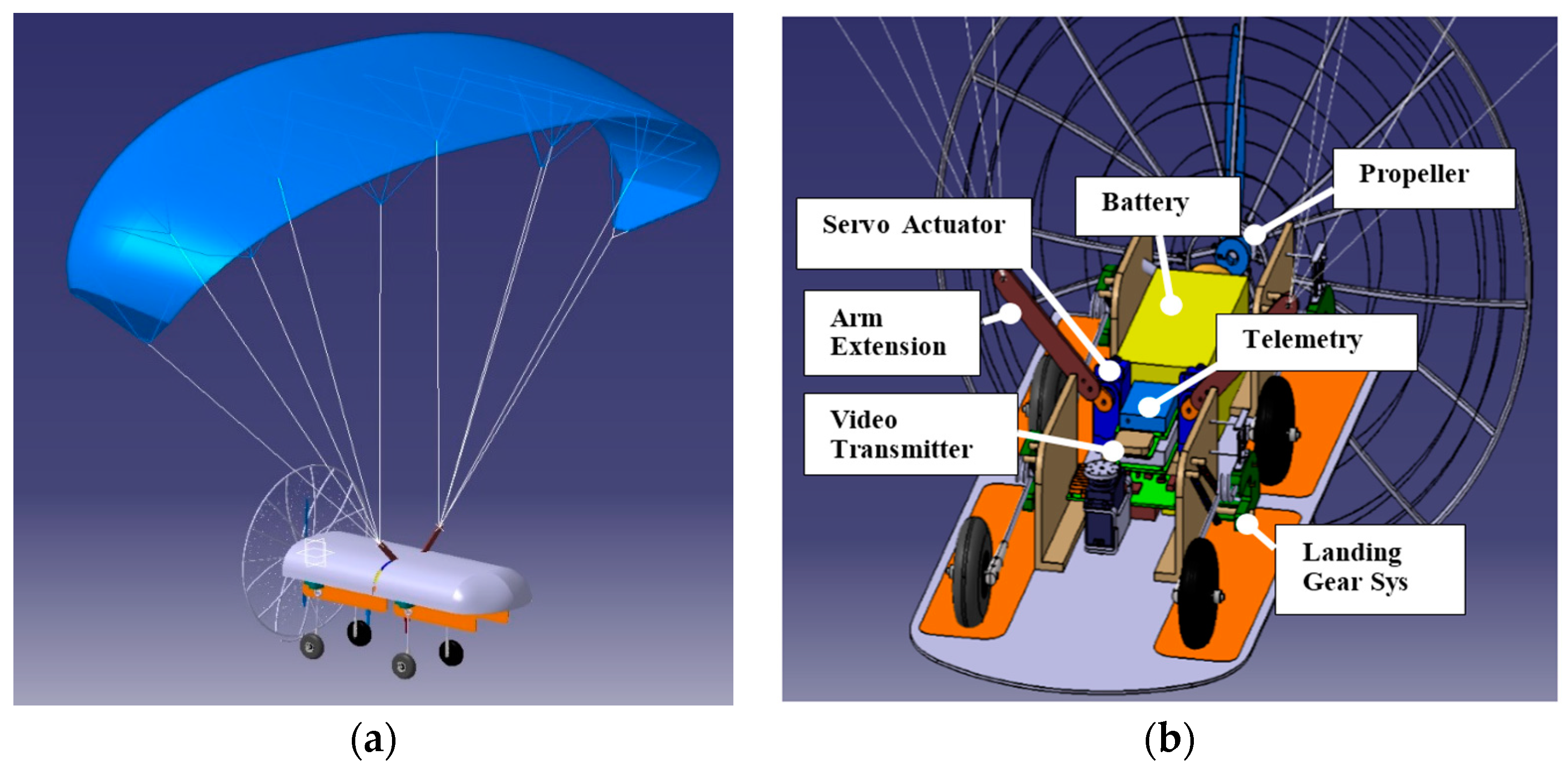
In
Figure 1, the main components of the cited UAS are shown, namely the sail, the fuselage and the interior systems. The main system features are reported in
Table 1.
The system is conceived to perform missions at low altitude (300 m above the sea level) and short endurance (1 h). Different payloads and sensors can be installed, depending on the selected mission (fixed and mobile targets identification, border patrol, traffic control and many others, involving also civil applications). The main subsystems are the fuselage and the parafoil (or “sail”), connected to the main body by wires. The fuselage hosts the flight control unit, the power supply, the engine, the payload, and the landing gear. All the components are designed to allow compact packaging and rapid deployment on the ground, to keep the system mass, complexity, and cost low.
A peculiar aspect of this system is the ability to land on very different runways, according to the different missions. Therefore, the landing gear must guarantee the right flexibility and damping to protect the payload. Following this necessity, CIRA has developed landing gear, driven by a shape memory alloys (SMA) system. SMA active elements regulate the deployment of the landing gear on take-off and landing, whereas SMA bias springs assure the retraction during cruise [
15].
In the paper at hand, the working principle of a SMA-based landing gear is described, highlighting the function of its main components and the way they interact each other. For this purpose, dedicated structural schemes are conceived, and used as reference for designing the retracted and the deployed configurations. Starting from system and mission requirements (available room within the fuselage, weight limits, available energy, activation time, and so on), the design phase is carried out: the main system parameters are first identified, like the springs characteristic, their layout and their connections with the landing gear arms; then a suitable numerical model is developed, able to fix its features and predict its performance, and finally a dedicated conceptual mock-up is manufactured, reproducing the arm rotating shaft, the pivot connection element with the SMA springs, and the springs themselves.
The system functionality has been evaluated in terms of ability in deploying and retracting the landing gear and the demonstrator has been tested for several cycles, giving evidence of the working process repeatability and reliability. The evolution of kinematic and thermodynamic parameters (arm rotation and SMA temperature) is finally presented, giving evidence of the strong relation between them during system activation and de-activation.
2. Working Principle and Design Requirements
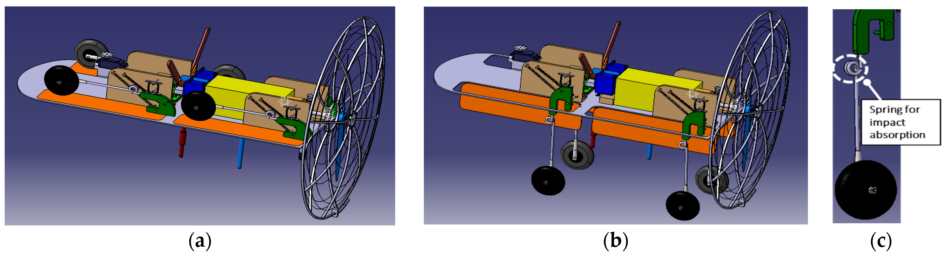
The landing gear system proposed in this work is conceived to give rise to the complete deployment of its arms on take-off and landing and to guarantee their full retraction during cruise and other flight phases.
Figure 2 shows an open view of the fuselage in these two moments. The landing gear is made of four arms intrinsically able to absorb the impact loads without any additional damping mechanism. A 90° rotation of the arms around the pivots shall be produced by the SMA actuation system. For lateral stability issues, the rotation plane of each couple of lateral arms has a 2.5° slope with respect to the vertical symmetry plane. Each arm is constituted by an aluminum alloy stick with a spring in order to absorb the impact energy.
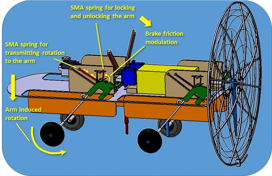
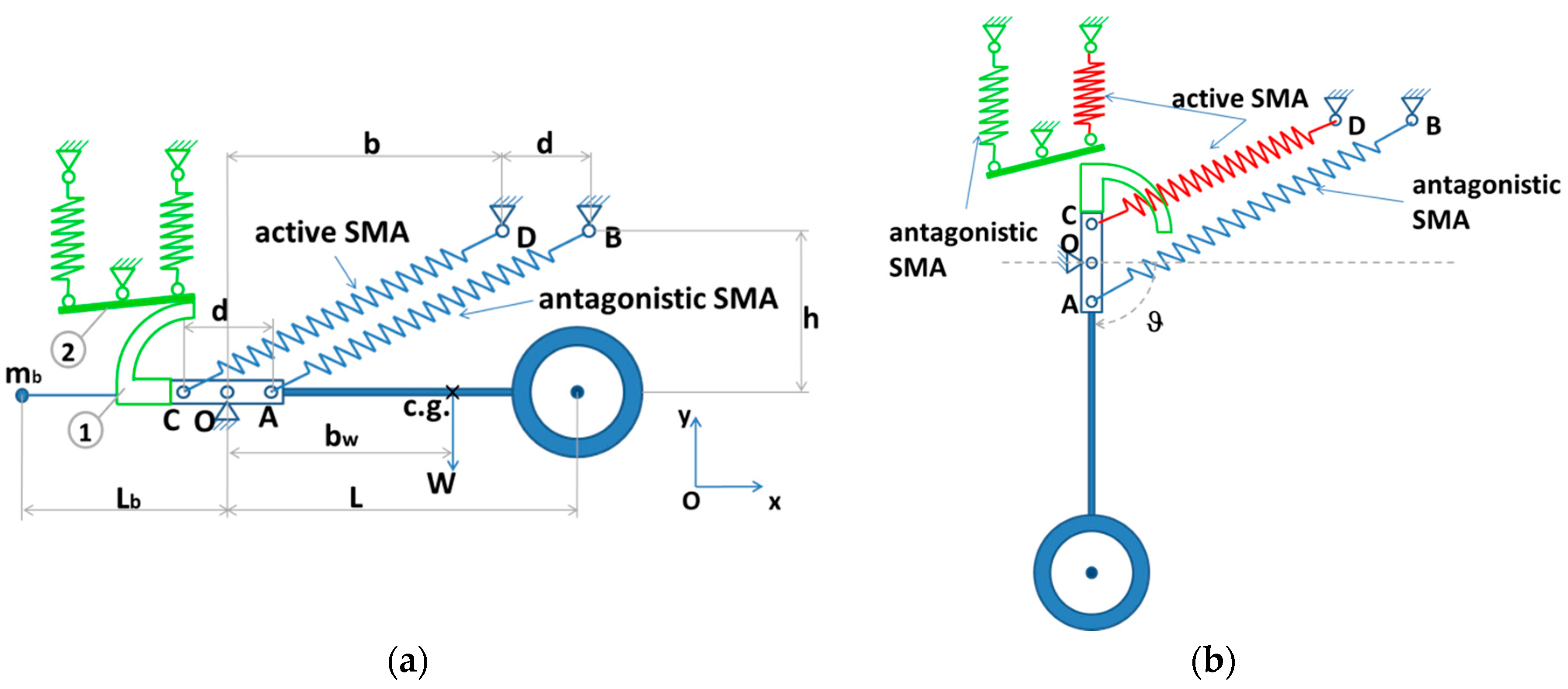
The landing gear herein proposed consists of two main subsystems, both based on SMA technology: the deployment-retraction and the blocking subsystems. The former is made in turn of two bias SMA springs whose super elastic behavior falls within the UAS temperature working range. They are pre-stressed around the arm pivot and reach equilibrium once the landing gear is retracted,
Figure 3a. The top spring heating shall cause the alloy changes its phase, with an increment of its rigidity; as a consequence, the equilibrium point shifts and a rotation ϑ is induced towards the deployment direction,
Figure 3b.
Points A and C, spaced by a distance d, represent the connections of the springs to the shaft O and are symmetric with respect to the shaft itself. The springs are parallel and connected to the fuselage body at the points B and D. The dimensions b and h define the positions of these points with respect to the shaft O in the adopted reference plane. The center of gravity (c.g.) of the arm-wheel system is at a distance bw from the pivot. A mass, mb, on the opposite side of the pivot, balances the weight of the arm-wheel system. It is possible to increase the internal stress of the antagonistic spring to achieve the same balance, but this would have led to an additional pre-strain, exceeding material stress limits.
The blocking subsystem (green sketch,
Figure 3) is introduced to guarantee increase stability to the retracted and the deployed configurations without significant oscillations. It is in turn made of two parts, one rigidly connected to the hub AC and the other one actuated by two further SMA antagonistic springs. These latter are also pre-stressed, so that the brake component (2, circled in the figure above) is pushed against the rotational component (1, circled in the figure above) to clutch it. The activation of the spring on the right,
Figure 3b, synchronous with the activation of the top spring of the deployment subsystem, unlocks the hub and allows opening the landing gear.
Once the working principle is described, in order to design the landing gear system, the following requirements are set:
Deployment rotation and response time: the SMA system must guarantee a rotation equal to or larger than 90° within 10 s. Due to SUAS mission requirements, above all altitude and air speed, a 10-s time is sufficient to guarantee the right landing procedure. More in detail, the reference UAV has a 350 m operative altitude and a 1 m/s descent rate. The idea is to open the landing gear at 100 m altitude, and after 10 s, to continue the descent for about 90 s with a fully deployed landing gear.
Arm retraction: the arm must be completely stowed within the fuselage within 150 s from take-off.
Weight: the total weight of the landing gear actuator system, including the hub and the clutches, must be less than 30 g. This is one of the most important strengths of the system. In fact, this kind of device weighs about 50 g for models up to 5 kg. More in detail at the present project stage, the low smart actuator weight allows the possibility of onboarding a pan & tilt camera, able to monitor woods/forests, in support of Civil Protection and State Park Rangers patrols during fire-detection missions, or monitoring the zone of disaster in support to emergency teams, and so on.
Power-energy supply: power absorption shall be lower than 4 W. Assuming a 10 s deployment time, this value corresponds to 0.01 Wh.
Room: the available volume is 7 cm × 10 cm × 5 cm.
3. Sizing the Shape Memory Alloys (SMA) Deployment Subsystem
The design process referred to the structural schemes, illustrated in
Figure 3. Parameter
d (distance between points A and C) was fixed after a compromise between two opposite necessities: maximizing the transmitted rotation (conversely proportional to
d) and avoiding interferences between the springs during the activation phase (directly proportional to
d).
Distances
h and
b are instead set after considerations about the necessity of avoiding overlaps and fitting the available room. Assuming two springs whose features are reported in
Table 2, these geometric values resulted:
d = 2 cm,
h = 6 cm and
b = 7 cm. More in detail, the parameter
d has been assumed equal to the distance between the spring connections to the gear arm (points A and C of
Figure 3a); this assures the parallelism of the two spring in fully retracted condition. Note that, for the retracted configuration, the two springs are in the closest relative position. When activated, they move away each other (as shown in
Figure 3b) avoiding any interference. The distance of the connections A and C has been chosen to guarantee a full conversion (more than 90° of rotation) of the spring linear displacement into rotation around the arm pivot O. The parameter
h, that is the vertical distance between point A and C and between B and D, was chosen as the maximum allowable for the internal space (fuselage height), thus preventing as much as possible any mechanical conflict between the two springs; finally the parameter
b was chosen to assure, in combination with already fixed
d and
h the necessary stretched length of the two springs.
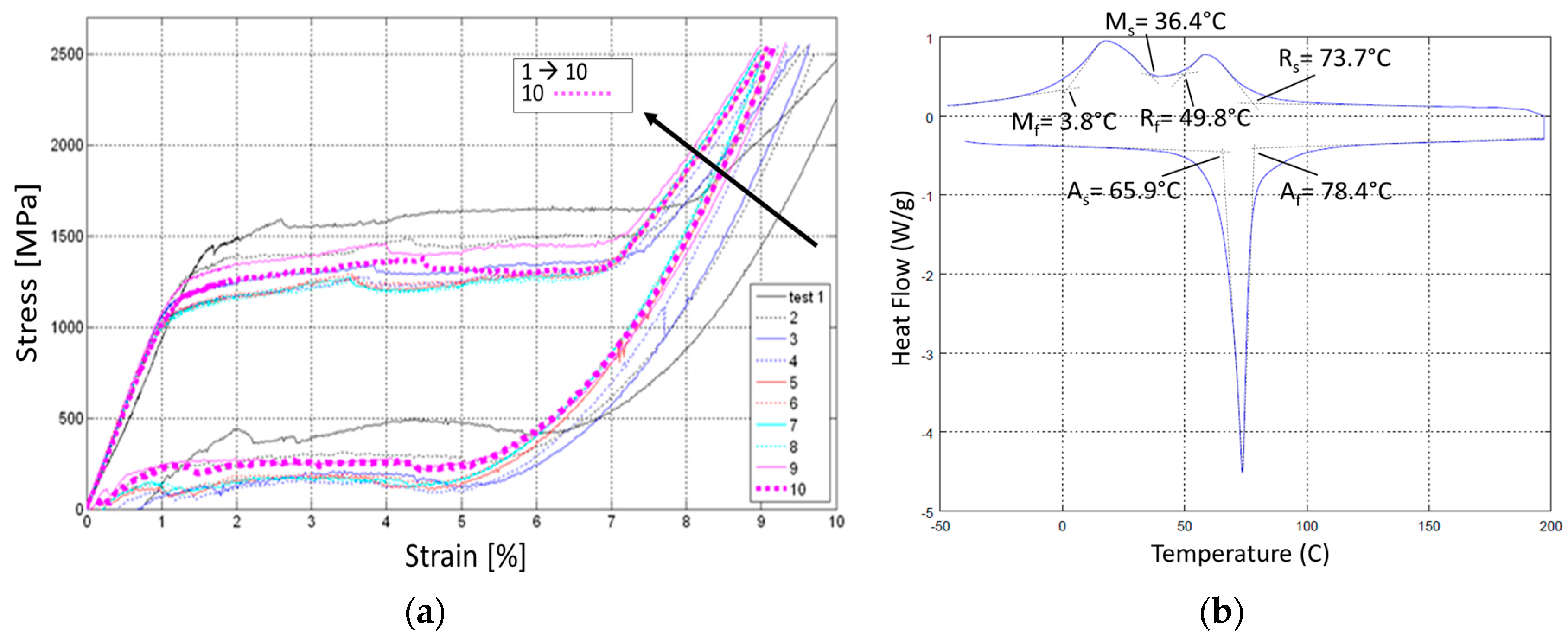
The material chosen for the springs, NiTiNol (Ni 49.8%), was experimentally characterized; the Austenite and Martensite Young moduli were determined through tensile tests (also aimed at stabilizing the material) and DSC measurements. Achieved results are illustrated in the graphs of
Figure 4. After seven cycles, the curve convergence (stabilization) was observed.
The analyses hereafter illustrated prove the correctness of that choice.
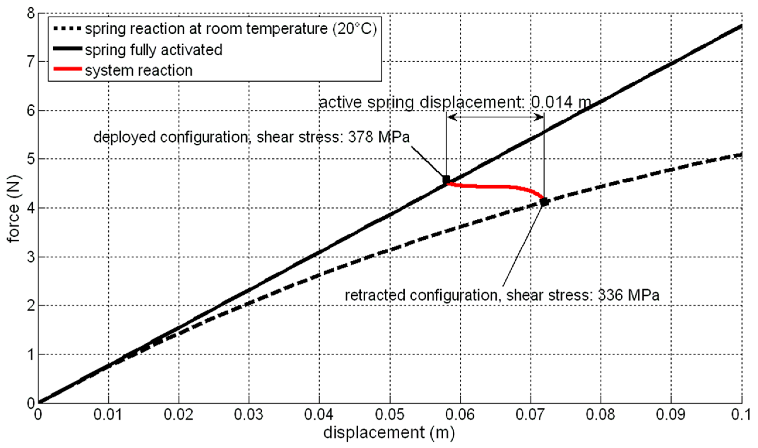
At first, the springs were experimentally characterized for having an estimate of the elastic reaction; in
Figure 5, the force, displacement curves at room temperature (20 °C) and for the complete activation (full austenite) condition, are plotted. The upper curve refers to the pure austenite condition; this curve is obtained by keeping a temperature higher than the minimum one necessary to have full austenite at a certain stress level; the lower curve, on the other hand, refers to a partial martensite concentration (see Ms and Mf values reported in
Table 2); as the load arises, since the temperature is kept constant, the transformation into martensite progresses. In practice, the higher the axial force, the higher the torque moment acting onto the wire cross section; this leads to larger tangential displacements of the external zones of the wires, where austenite transformation into martensite starts.
These springs are in martensite phase at room temperature, without applied load (see transformation temperatures reported in
Table 2).
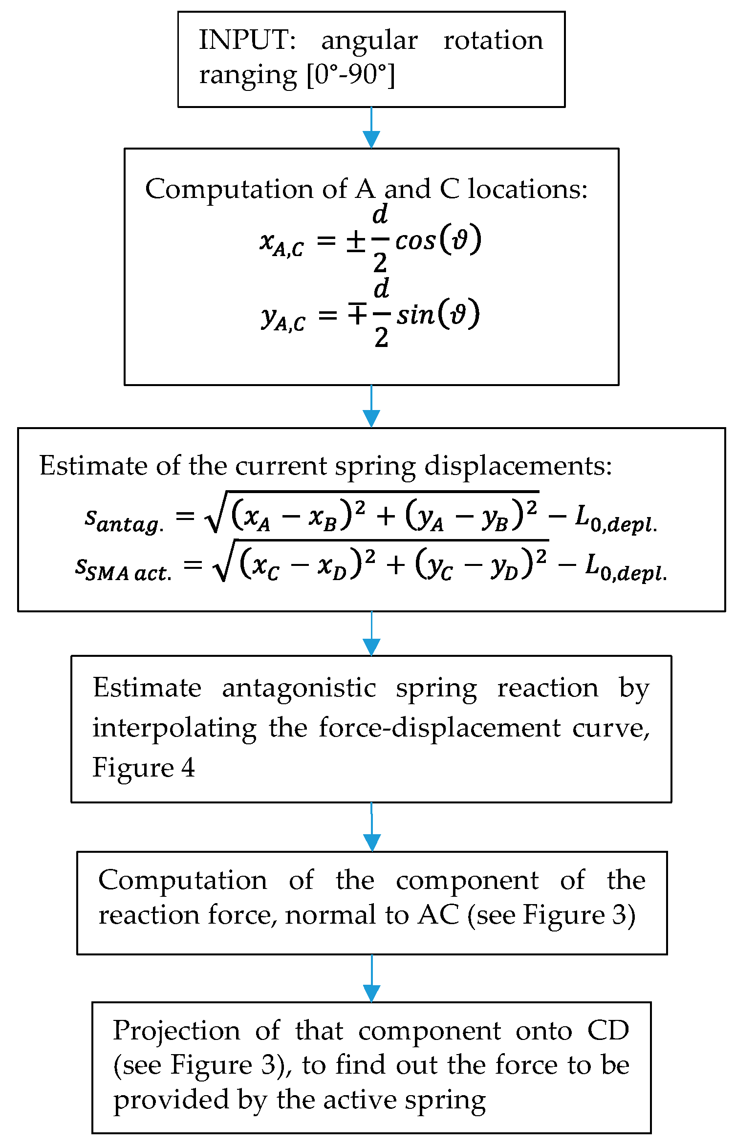
The approach illustrated in
Figure 6 is instead used to verify that the selected geometric parameters value effectively meet the original specifications.
Each angular rotation, ϑ, is, in fact, related to the spring length (i.e., the distances of A and C from B and D, respectively). For the bias spring AB it is thus possible to compute the elastic reaction at the point A. The force component normal to the segment AC is then projected onto the CD direction (active spring orientation) to evaluate the balance force the active spring must provide.
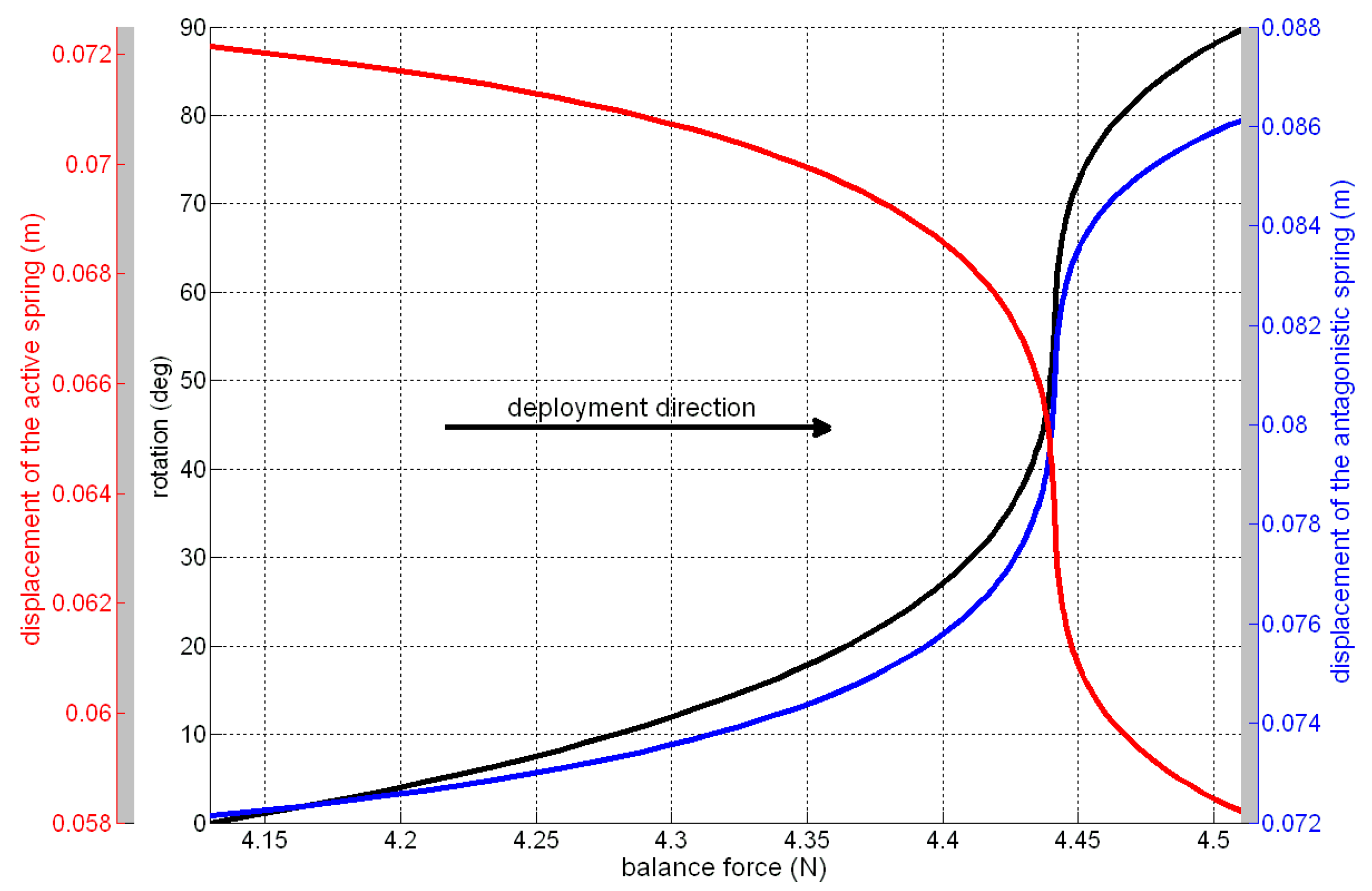
In
Figure 7, the rotation around the pivot, the displacement of the bias, and the active springs are plotted
vs. the balancing force. This latter curve plays a critical role for the design, representing the system rigidity as perceived by the SMA active spring, and can be used to graphically estimate the non-activated (arm retracted) and activated (arm deployed) equilibrium conditions.
The nonlinear behavior of the system is highlighted by the remarkable slope variation of the force-rotation and force-displacement curves, mainly due to the springs’ nonlinear force-displacement law,
Figure 6, and to the variation of the distances of the force application points from the pivot.
The system action, as perceived by the SMA active spring, intersects the non-activated (black dashed line) and the fully activated (black continuous line) force-displacement curves in two different points, corresponding to the retracted and fully deployed configurations,
Figure 7. A 16 mm displacement is required to the active spring, to achieve the desired deployment. The shear stress level,
τ, within the antagonistic spring is evaluated by [
20]:
being
F the force acting on the spring,
Ds and
dw the spring and the wire diameters. A maximum value of 378 MPa is found for the fully deployed configuration, well under the allowable limit of 450 MPa. Equation (1) comes from the torque equilibrium of the wire of the spring. This torque moment is the result of the axial force applied to the spring, which is transmitted at each cross section of the wire as rotation and thus as shear action. The relation between the applied axial load
F and the elongation produced is not linear during the load cycle; however the present study aims at comparing two well-established, extreme configurations: no activated (pure martensite) and fully activated (pure austenite and at such a temperature to assure the only austenite for the occurring stress level).
The balancing mass,
mb, was finally estimated by assuming a complete compensation of the arm-wheel weight momentum around the pivot,
MW.
Assuming a 10.0 g mass for the arm-wheel system and a 0.170 m length for the arm (c.g. at 0.127 m from the pivot), MW resulted equal to 0.025 Nm. A 31.8 g value for mb then results, Equation (2), having fixed its distance from the pivot, Lb, at 0.080 m.
4. Sizing the Locking Subsystem
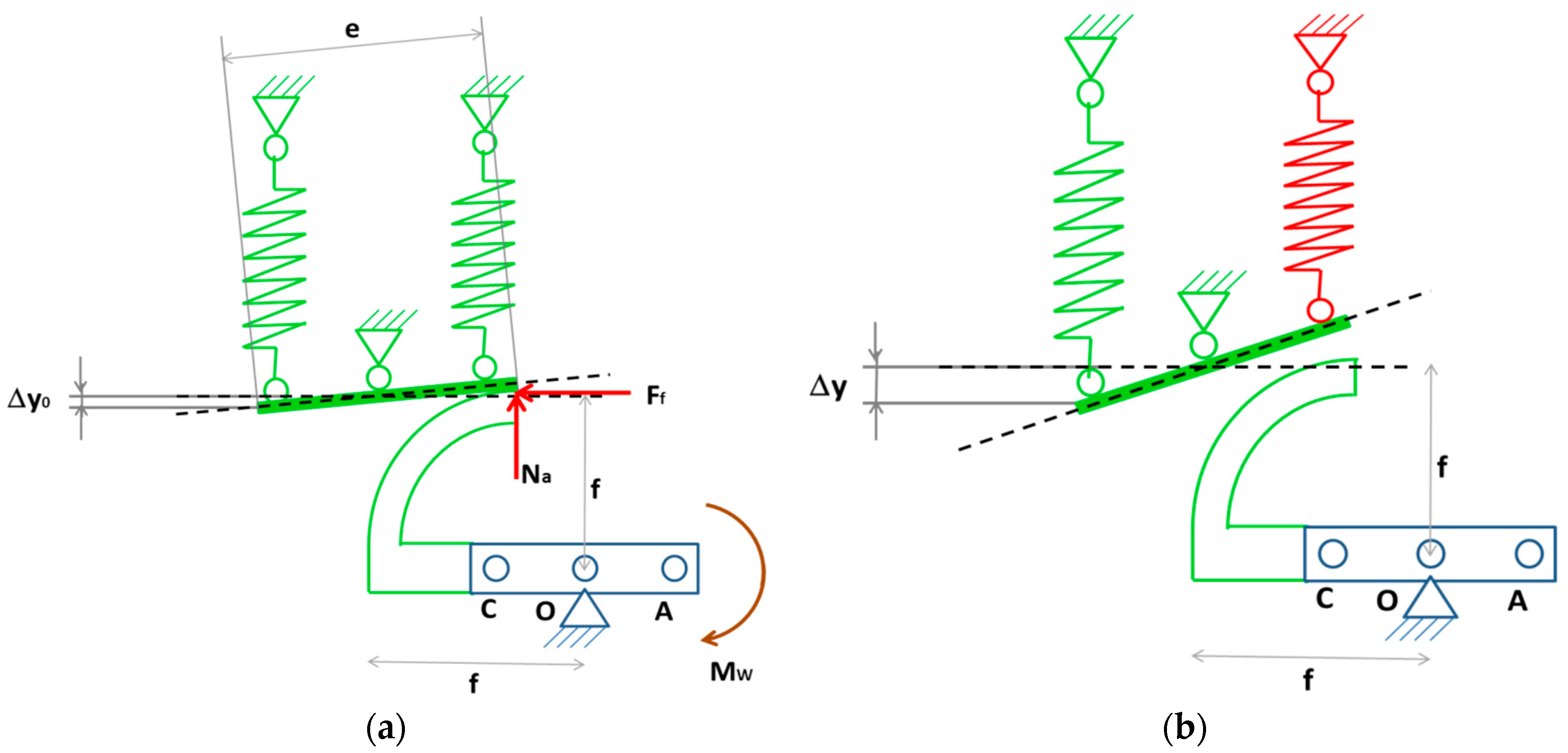
A detail of the structural scheme of the locking subsystem is illustrated in
Figure 8. The system releases the landing gear arm during the entire motion (deployment-retraction), while it keeps the arm blocked when fully retracted and fully deployed. The release occurs activating the small spring of the locking system, on the right (see
Figure 8b).
Landing gear rotation around O is avoided through the contact friction force
Ff, between two aluminum elements, namely: a circular slide connected to the gear arm and a friction element (runner), having a length e and connected to two passive springs,
Figure 7a. In the blocked condition, the springs undergo a displacement Δ
y0, forced by the initial slide layout. The activation of the right spring produces a further displacement Δ
y, generating a gap between the two elements and then allowing the arm rotation,
Figure 8b.
The first step to size the system components is to estimate of the friction force able to balance the downward weight moment around the pivot O. This equilibrium can be formalized as:
where the right and left sides express the friction and the arm-wheel weight momentum, respectively. The Equation (3) neglects, conservatively, the concentrated balancing mass,
mb, effects. If the slide has a 0.050 m radius,
f, Equation (3) gives a 0.49 N balancing friction. Considering a friction coefficient µ = 1.4, a 0.36 N normal action, N
a, resulted. The friction coefficient was assumed as average within the aluminum-aluminum contact component range reported in [
21]. It is worth noting that a normal force of 0.36 N is the minimum value necessary to assure a balancing couple and, thus the locking; it is possible to increase the stretching of the bias spring on the left; this will have the beneficial effect of increasing the friction and thus the lock performance.
For this case, two springs were used of the same material, external diameter and wire diameter of the ones used for the deployment subsystem; the only difference is the no loaded length, L0,lock., and the number of windings, 5.5 mm and 7 mm, respectively.
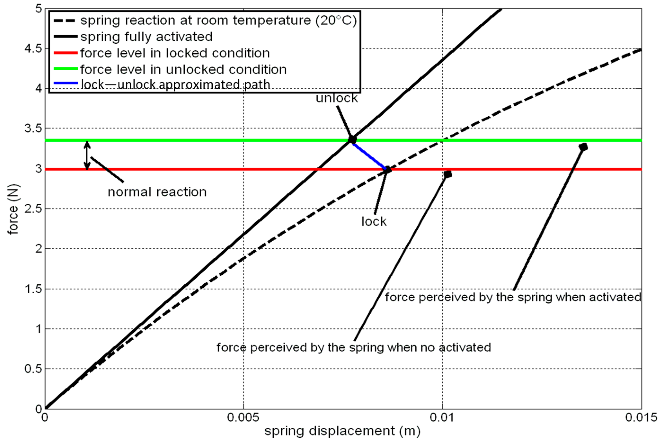
The active springs perceives two actions: the reaction due to the antagonistic spring and the normal action due to the contact. Since these forces have opposite sense, if the stretching of the active spring is low, it risks working in compression; however, the stretching cannot overcome a certain level, for the material shear stress limitation. Considering the above mentioned value of
L0,lock., an imposed stretching Δ
y0 of 10 mm would lead to an acceptable shear stress (206 MPa, computed through Equation (1)) and would generate the situation illustrated in
Figure 9.
In this figure, both the no activated (room temperature) and fully activated force-displacement curves were reported for the active spring (dashed and solid black lines, respectively). The spring is initially in equilibrium in lock condition. The corresponding point is identified by the intersection between the black dashed line and the red line, representing the force level acting onto the active spring, given by the antagonistic spring reaction minus the normal force, Na. The activation of the spring causes a sudden decrease of the contact normal force that goes rapidly to zero. The blue line just connects the initial locking point with the final unlocking point, but does not represent the real path of the transformation, being nonlinear because of the nature of the contact force. The force perceived by the active spring (green line) is at the end of the greater transformation. The difference between the green and the red curves is precisely the normal action (0.36 N).
5. Integration within the Unmanned Aerial System
After defining the static and dynamic behavior of the SMA based subsystems, the integration problem was dealt with [
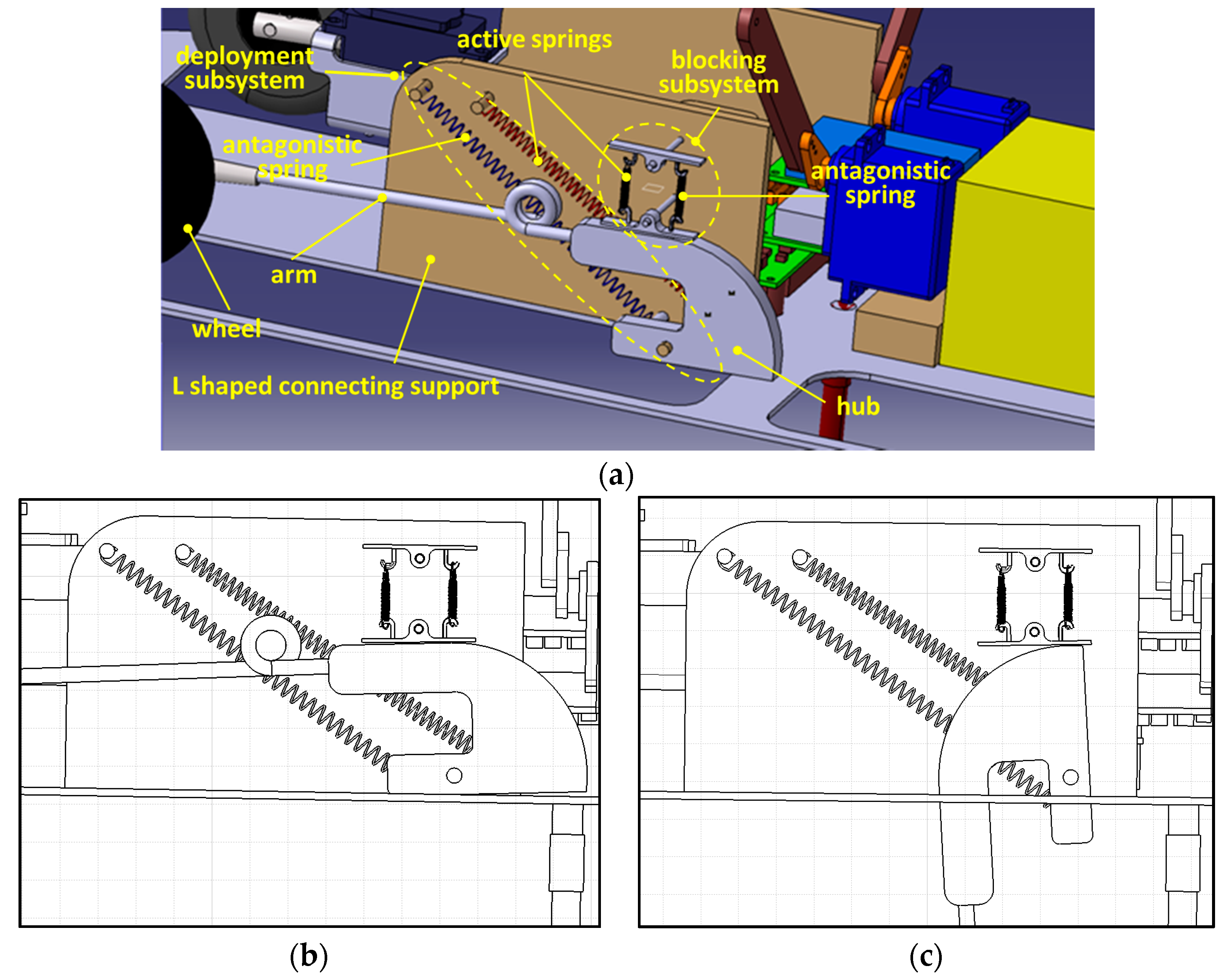
22]. After some preliminary tradeoff between requirements and design, we decided to place the four arms, integrated with the SMA springs within the available space (see the specifications); after hypothesizing a housing compatible with the retracted, deployed, and intermediate configurations, the dimensioning of the supports was addressed. The chosen solution had to guarantee a solid and robust connection with the inner supporting structure of the UAV and assure the gear deployment as from the conceptual design. Some computer-aided design, CAD, schemes are reported below, in order to highlight the integration aspects of the system.
As shown in
Figure 10a, “L” sized plate elements, namely “connecting supports” were used as link between the deployment system and the UAV supporting plate. According to the design outcomes, the hinges of the springs and the hubs were placed on the connection supports. The hubs were realized through flanges circularly shaped on one side for sliding onto the runner of the locking subsystem, and finally, the springs of the two subsystems were mounted in antagonistic configuration, in equilibrium in retracted attitude.
The main features of the SMA landing gear system are reported in
Table 3.
6. Functionality Tests
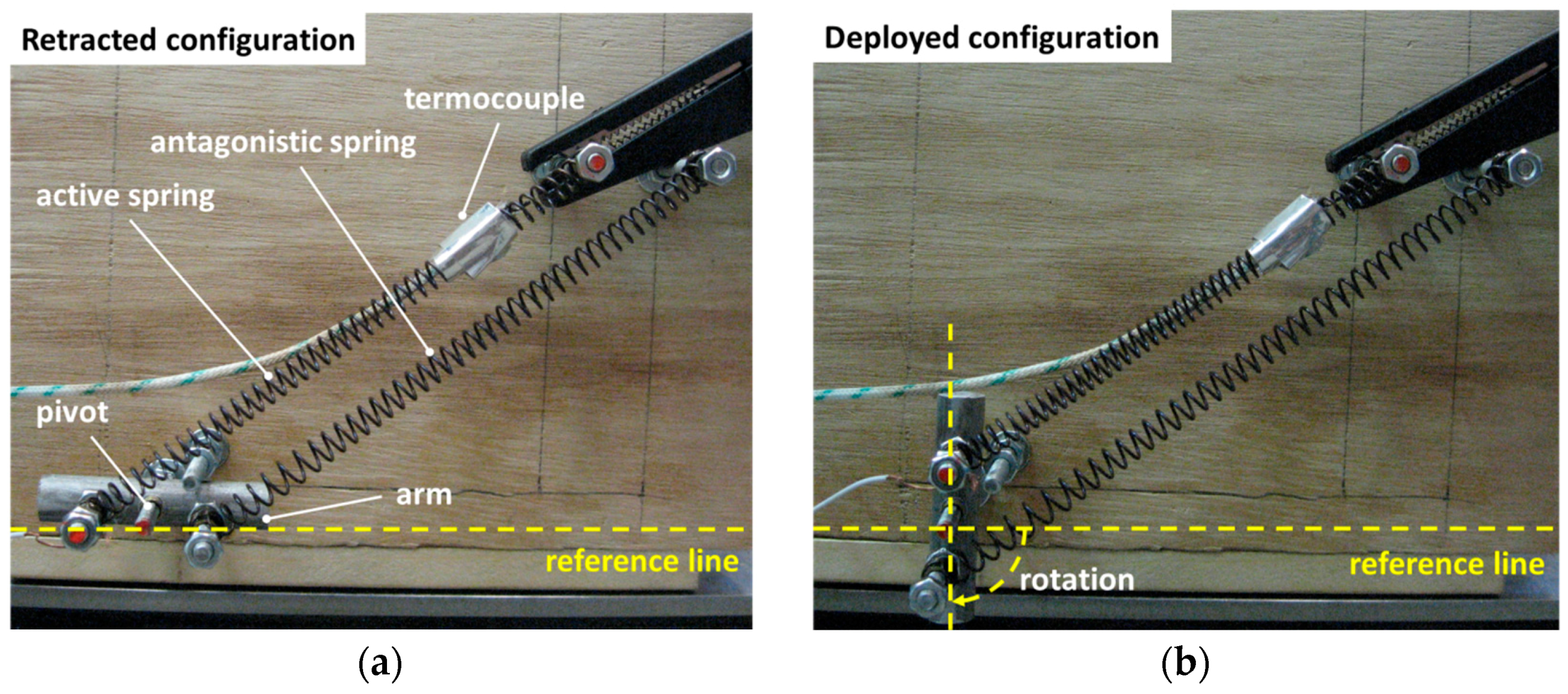
In order to verify design approach and assumptions, we realized a conceptual “test specimen” able to reproduce the structural scheme of the deployment subsystem. It consisted of a supporting structure on which holes were drilled at the pivot and at the spring anchoring hinges (points O, B and D, respectively). Shafts, integrated with bushes reducing the friction, were placed into the holes. Then, the shaft on point O was integrated with a drilled aluminum component, supporting the hinges A and C. A retainer shaft element was added as shown in
Figure 11a, to avoid undesired crossing of the horizontal position during the retraction. Two identic springs featured as specified in
Table 2 were mounted. The shafts C and D were connected to power supply terminals to heat the top spring and they were integrated with a thermocouple and an angular sensor (Linear Variable Displacement Transducer, LVDT).
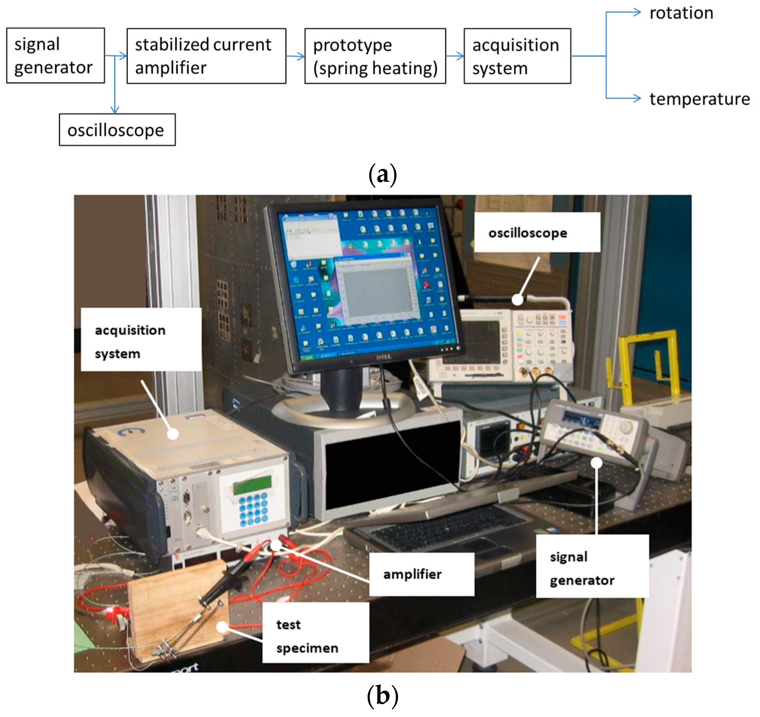
A dedicated experimental setup was assembled to execute the tests (see the scheme and a photograph in
Figure 12). The instrumentation reported below was used for this scope:
Acquisition system: IMC Cronos PL/8, Sampling rate 20 kHz;
Oscilloscope: Tektronix—TDS 3014B, Sampling rates to 5 GS/s;
Power supply: DELTA Elektronika ES 030-10: 0–30 V, 0–10 A;
Signal generator: Agilent 33220A, 14-bit, 50 MSa/s;
Temperature sensor: K thermocouple; measurement range: −200–1260 °C, sensitivity: 41 µV/°C;
Angular sensor: BOURNS-3590S-2-502L—POTENTIOMETER; measurement range: 0°–3600°, resolution: 1°.
Thanks to the signal generator instrument and using the function “generator”, a step signal was produced to drive the amplifier, this way supplying the prototype with an “on-off” current law.
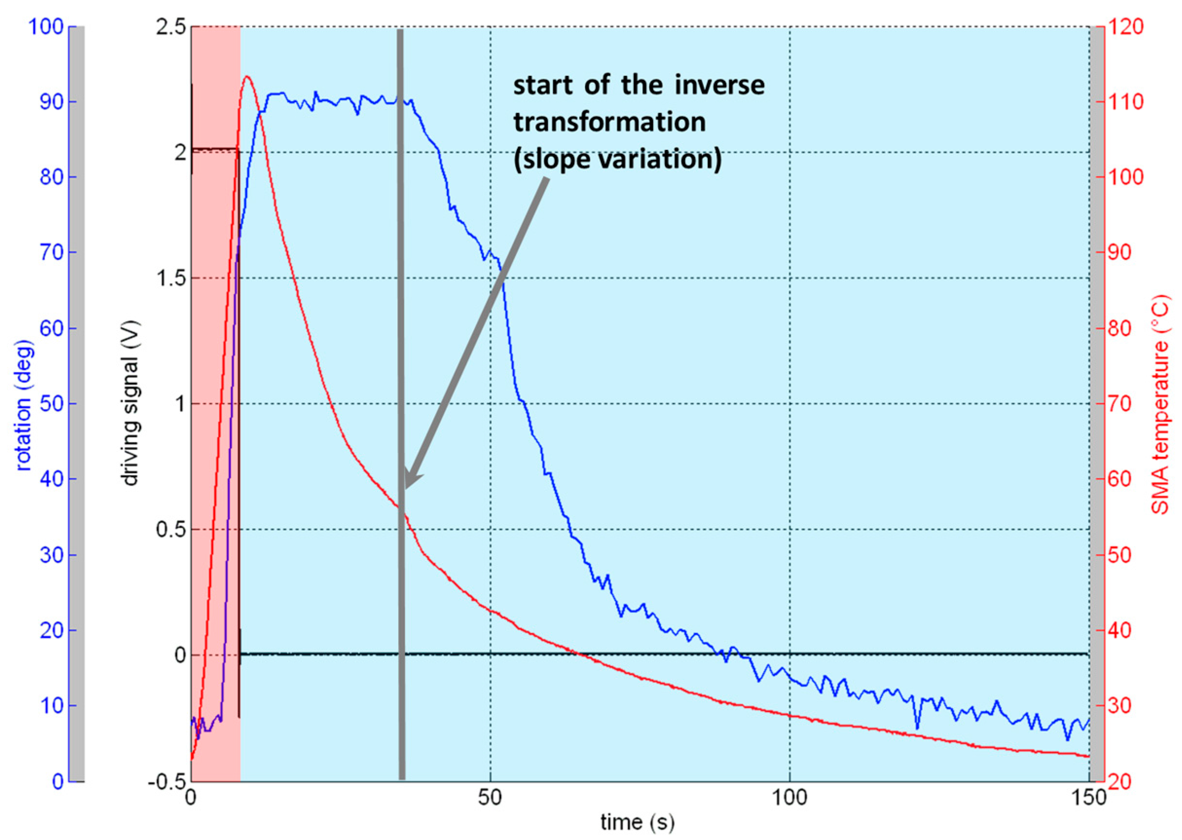
Figure 13 describes a single deployment-retraction cycle. The period of the cycle was set to 150 s, and split into two phases: the activation–deployment phase and the deactivation–retraction phase. The black line describes the logic-driving signal produced by the function generator, assuming a non-zero value in the first 8 s of the cycle. Within this time, the circuit is supplied with 0.5 V–2.3 A electrical signal. A sudden arise of the temperature was registered (red line). A maximum rotation of 90° was obtained for a temperature of 110 °C. At this point ends the deployment phase (red zone of the graph). It is important to note that, due to the thermal inertia of the spring material, after the power supplier shutdown the temperature continues to arise for about 1 s up to 113 °C. After this, the cooling starts (light blue zone of the graph), but the system remains in the fully actuated condition for 29 s until the inverse transformation starts, highlighted by the slope variation of the temperature line (see
Figure 13). The transformation starts at 56 °C and a time range of 113 s is needed to come back to the retracted condition and to arrive at room temperature.
Figure 13 shows that, due to the pre-load level, the temperature transformation value, from austenite to martensite, is reasonably higher than the value (Ms temperature) reported in
Figure 4.
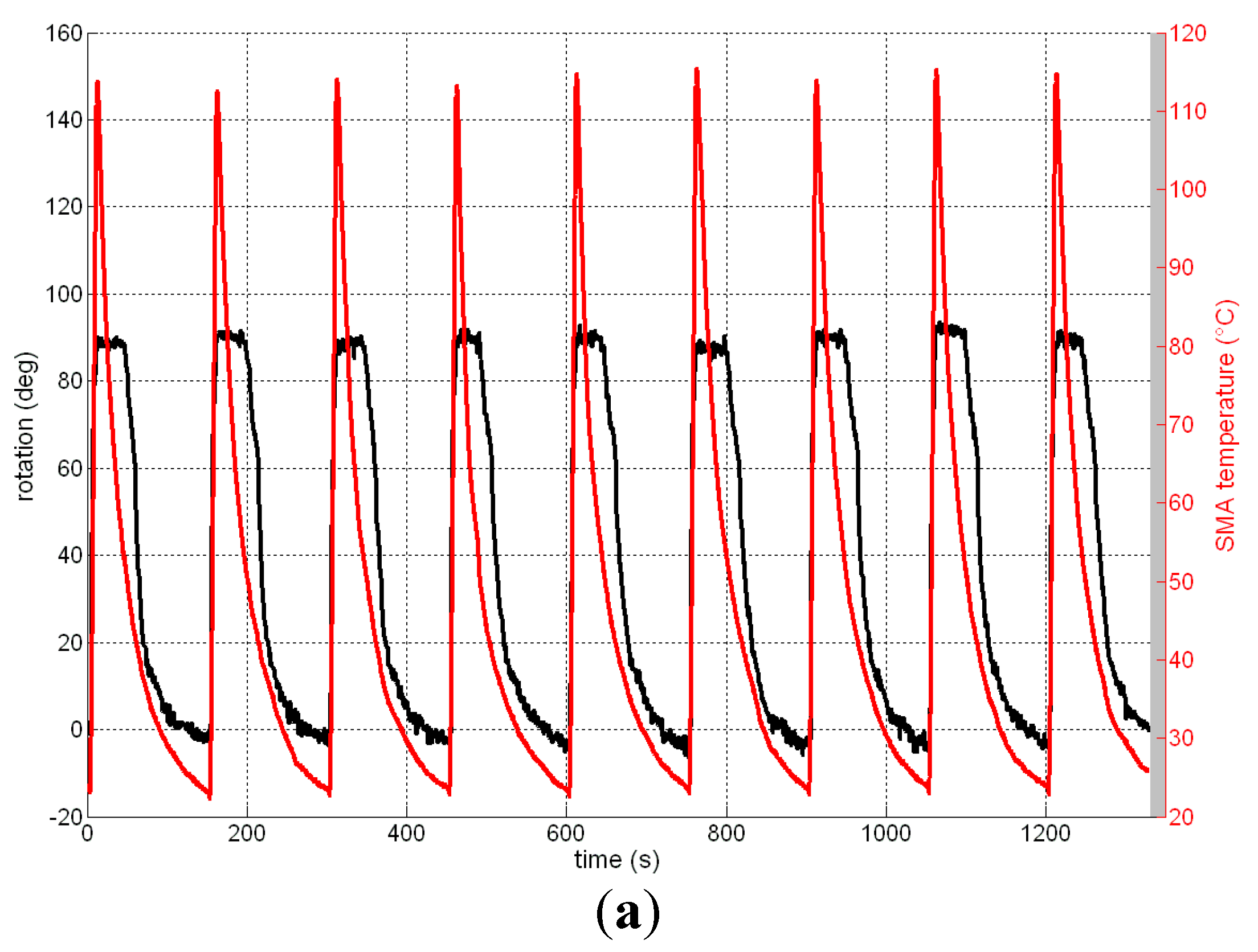
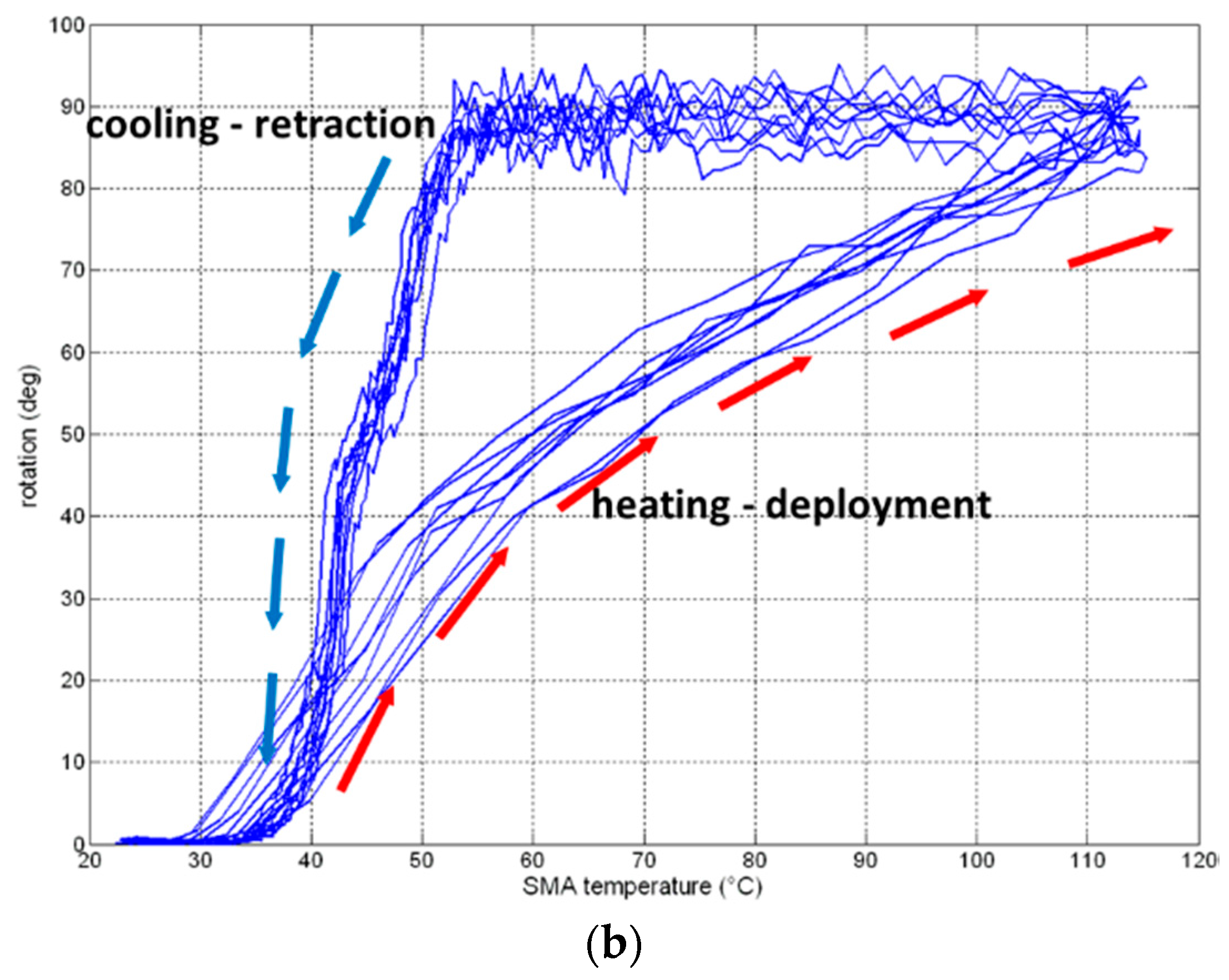
The above mentioned cycle was repeated different times to verify the system performance repeatability. In
Figure 14, on the left side, some rotation-temperature cycles are reported, giving evidence of the possibility of covering the required rotation of 90°. On the right side of the figure, rotation
vs. temperature cycles are reported to give an idea of the overlap of the cycles.
7. Comparison with a Conventional Actuation System
The design and development of landing gear encompasses several engineering disciplines such as structures, mechanical systems, aerodynamics, material science, and so on. The conventional landing gear design and development for aerospace vehicles is based on the availability of several critical components/systems such as forgings, machined parts, mechanisms, sheet metal parts, electrical systems, and a wide variety of materials such as aluminum alloys, steel, titanium, beryllium, and polymer composites. As the science of materials is progressing continuously, it is natural that the use of new materials will replace older designs with new ones, like ones with smart material spring as actuator.
Current small unmanned aerial systems and aero models, typically, use servomechanisms linked to retractable landing gear to provide leg activation/retraction.
A servomechanism consists of a large number of moving parts such as gears, bearings, shafts, motor coils, etc. The complexity of a servo requires a considerable percentage of the volume, power, and weight of the entire UAV. Moreover, the reliability of the system strongly depends on the number of components moving each other’s. One of the purposes of the design presented in this work was the global simplification of the actuation part, basically constituted by monolithic actuator components (active springs), whose action is modulated through identical springs (working in an antagonistic way).
A comparison was performed between a conventional servo actuator, used for this kind of application [
23], and the SMA based one.
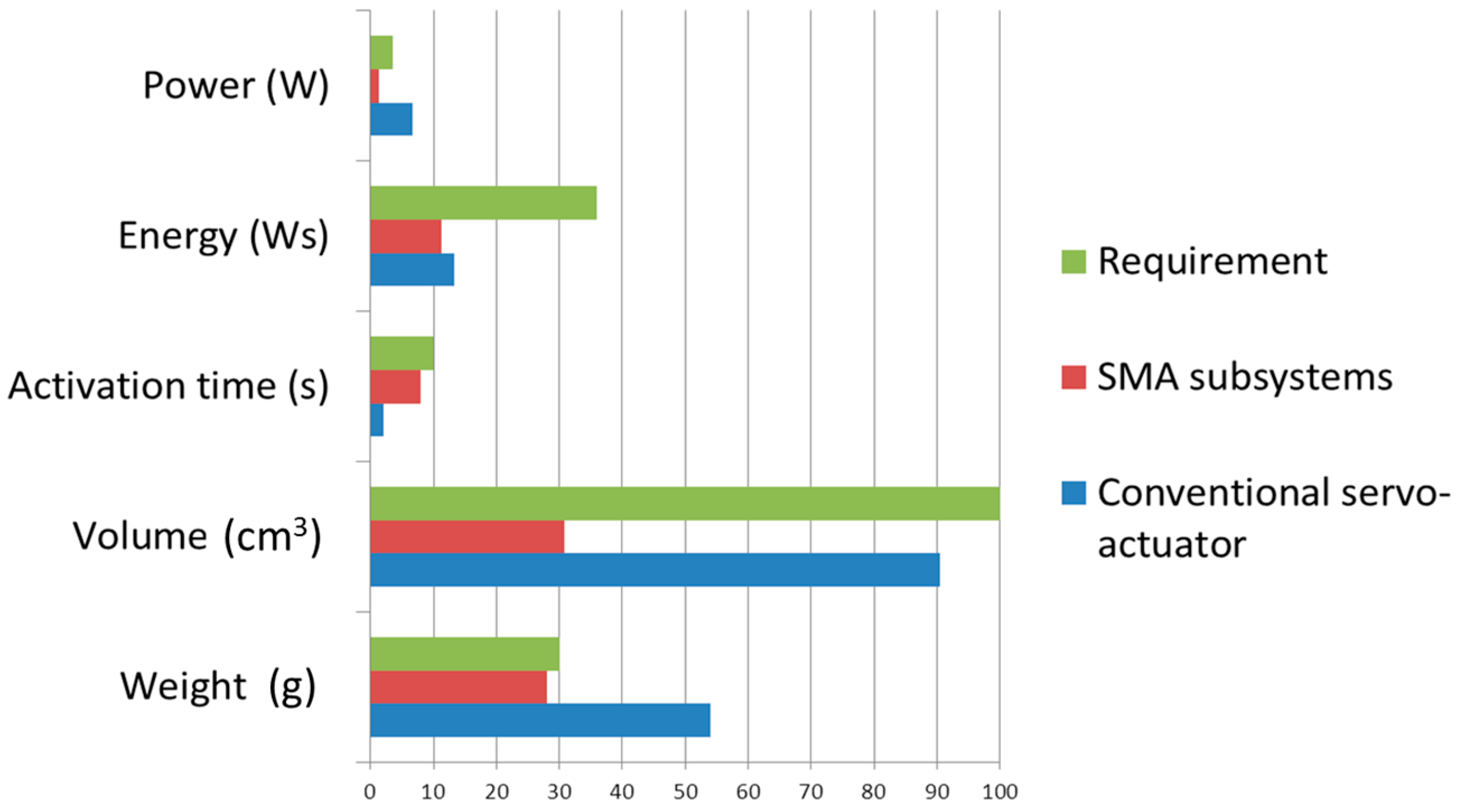
When designing for a particular application, several key parameters are specified, including output force, displacement, and frequency. Size and power constraints may also be specified. Based on these few parameters alone, it is desired to be able to look at the vast array of existing actuators and see which candidates match. It is important to realize the entire spread of possibilities and alternatives to meet the requirements of a given application. The weight, the housing volume, and the required power were taken into account and compared in
Figure 15 and in
Table 4.
Let us note that comparisons, based directly on design parameters, will be more useful in the design process. In performing the comparisons, one of the key objectives is to include size (either mass or volume), so the effects of scaling can be observed. It is well known that scaling can have a large effect on some actuation schemes. For the designer who works in several domains (e.g., micro and macro devices) this information is important.
8. Conclusions and Further Steps
In the paper at hand, the design of landing gear, based on the shape memory alloy technology, was presented. The system, conceived for a small unmanned aerial vehicle, is made of two subsystems, namely, the deployment and locking subsystem. The former one assures the deployment and the retraction of the arms, the latter one assures the maintenance of the fully deployed and retracted attitudes by locking the arm through a friction action.
Both the subsystems are actuated through SMA springs, whose retraction is assured by other identical springs, working in antagonistic way. In the deployment mechanism the springs are mounted around the arm pivot; the heating of one of them leads to an equilibrium shift, with a consequent induced rotation. The locking mechanism is constituted by a runner hinged around a pivot around which two other springs act. When the active spring is cool, the runner is in contact with the arm slider this way avoiding any rotation; when the spring is heated, the runner rotates and releases from the slider enabling its rotation.
After a critical overview of the requirements, issued in terms of deployment angle, activation/deactivation time, system installation, weight, and dynamic behavior, the system’s working principle was introduced, describing the main design parameters and their effect on the performance. Then two reference structural schemes were introduced, referring to the equilibrium conditions in the retracted and the deployed configurations.
The evolution of the system from the retracted towards the fully deployed attitude was described. For each rotation value within the operative range (0°–90°) the corresponding length of the springs was found out on the basis of geometric assumptions. Then, using the experimental force-displacement curve of the springs, the reaction force of the antagonistic spring was obtained; finally imposing the momentum equilibrium around the arm pivot, the balancing force to be provided by the active spring was found out. In this way, the relation between the displacement of the active spring and the balancing force was obtained. By crossing this curve respectively with the spring not-activated and fully activated curves, the retracted and fully deployed attitudes were identified in terms of displacement and forces required by the active spring.
Based on the information given by the modeling task, a conceptual test specimen was realized. The arm pivot and the hinges of the two springs were placed onto a supporting plate. The pivot was integrated with a beam-like element representing the spring connection hub. After that, the springs were mounted with the prescribed extension so that the hub remained in horizontal position.
The top spring was then supplied by an electrical signal coming from an amplifier, driven by a function generator, in this way different heating-cooling cycle were performed, relating the rotation of the hub to the temperature of the spring and to the supplied electrical signal. The ability of the system to perform the full deployment was tested, as well as the repeatability of the performance.
Finally, a comparison of the main performance of the system was performed assuming as reference a traditional servo-actuator used for this kind of application.
The work presented highlighted the possibility to realize a deployable landing gear based on SMA technology and oriented to UAVs. The selected NiTiNol material proved to activate and deactivate at room temperature (20 °C) for the applied pre-load (see working cycle of
Figure 13). The extension of the use to a different and wider range of temperatures (typical for an aeronautical product of this class) can be obtained by selecting a specific alloy, having activation temperatures under the prescribed loads higher than the maximum operational temperature.
This choice is possible within the wide range of alloys offering activation temperatures in the wide range of −200 to +100 °C. In the present work, however, attention was paid to the mechanical feasibility of the concept, leaving to future studies the application to specific cases and the release of executive designs.
Further steps will be carried out and further efforts will be spent on this topic. The conceptual design above illustrated will be further developed and optimized up to arrive at an executive drawing of the system. The resulting device will be installed on board the UAV. Tests, both static and dynamic, will be addressed with the scope of characterizing the behavior of the landing gear integrated within the UAV and to highlight and solve eventual problems due to the interaction with the other onboard systems. Then the flight tests will be performed, monitoring with dedicated sensors the behavior of the landing gear components during a typical mission.


