Review

A Study on the Design and Implementation Technologies of EVA at the China Space Station

1
Institute of Spacecraft System Engineering, Beijing 100094, China
2
Beijing Aerospace Control Center, Beijing 100094, China
3
Beijing Institute of Technology, Beijing 100081, China
*
Author to whom correspondence should be addressed.
Aerospace 2024, 11(4), 264; https://doi.org/10.3390/aerospace11040264
Submission received: 4 February 2024 / Revised: 8 March 2024 / Accepted: 11 March 2024 / Published: 28 March 2024
(This article belongs to the Special Issue Advanced Spacecraft/Satellite Technologies)

Abstract

:
Extravehicular activity (EVA) is a key point and a difficult point for manned spaceflight tasks, as well as an inevitable trend in the development of the manned spaceflight industry. Equipment maintenance, load installation, and extravehicular routing inspection via EVA on the track are necessary to guarantee the safety and reliability of the long-term in-orbit operation of the China Space Station. In this paper, a comprehensive analysis was conducted on the features of multiple tasks, diverse working modes, and strong systematic coupling during the EVA of the China Space Station (CSS). On this basis, the design, implementation technologies’ development, and in-orbit performance evaluation during EVA were expounded. In the space station system, an extravehicular reliability verification and evaluation system suitable for the requirement for EVA under the conditions of China’s multi-mission, multi-module combination, and repairable spacecraft was constructed. Finally, the in-orbit EVA implementation of the China Space Station since the launch of the core module to the present was summarized, and the subsequent application of the extravehicular technologies in manned lunar landing projects and optical modules was anticipated.

1. Introduction

The extravehicular activity (EVA) of astronauts is an important part of manned spaceflight technology as well as an indispensable key technology to support the operation of space stations and expand the application services of space stations [1]. As a large multi-module complex configuration spacecraft, astronauts in the space station are required to complete a series of extravehicular operation tasks to achieve long-term reliable, safe, and stable operation in orbit, such as assembly of large-scale components, replacement of expired components, maintenance of faulty components, installation of extravehicular loads, extravehicular routing inspection, etc. [2].
The basic support technologies for the EVA at the China Space Station (CSS) mainly include airlock modules, EVA support technologies, support technologies for extravehicular spacesuits, support technologies for communication and lighting, and so on [3]. The present EVA technologies of space stations focus on long-term missions and have more diverse working modes, longer extravehicular time, larger coverage, better participation, better coupling of subsystems, and other features compared to those in the early stages of technological breakthrough [4]. And manipulators, recyclable resources, extravehicular wireless communication, and other new technologies have also been introduced. The astronauts are always facing risks throughout the process of EVA, covering long-term extravehicular operations (nearly 6 to 7 h), passing the lock, and returning to the sealed module [5]. In this paper, we identified different levels of hazard sources and formulated a safety guarantee criterion for the EVA system. The research can support the successful completion of the assembly and construction of the space station and the subsequent long-term mission for decades and provide valuable test data and experience for the EVA of astronauts in the combination of multiple spacecrafts [6]. The research results (such as pressure relief/recovery systems, a driving system for opening module doors, and manipulators for assisting astronauts’ transfers and operations) can be directly used in subsequent module expansion, extravehicular maintenance tasks, and the extravehicular installation of scientific experimental equipment.
The paper was based on the design factors in technical schemes for the EVA of the China Space Station, and mission objectives, detailed technical scheme design, and main technical characteristics are introduced and analyzed, respectively. The implementation of the EVA technologies in 14 extravehicular missions on the China Space Station was summarized, and the future application direction of the technology was projected. The author expounded on the application of the system design and implementation technologies of the EVA of the China Space Station in the development of China’s manned space flight from four aspects, including the design of extracurricular systems, in-orbit applications, future technical requirements, and China’s advanced extravehicular technologies.

2. In-Orbit Applications of EVA in the Low-Earth Orbit

Utilizing the near-Earth orbit space station for scientific experiments is a crucial field of scientific research using space resources. The microgravity, extravehicular vacuum environment, and extreme temperature variations in space are unparalleled by any environment on Earth. Astronauts performing extravehicular activities can engage in space station assembly, construction, and maintenance tasks, as well as operate and repair payloads related to scientific research conducted outside the spacecraft [7].
The space station, Mir, was taken out of service in 2001 after in-orbit operation for 15 years. In its service period, 36 astronauts completed 80 extracurricular missions, which can be classified into the four types below.
(a)
Installation and removal of equipment from the space station (nearly 55%);
(b)
Inspection and repair of the space station (nearly 24%);
(c)
Scientific or technical experiments;
(d)
Testing of manned maneuvering units and new-type extracurricular spacesuits.
For the active International Space Station, astronauts can exit the module through the joint airlock, Quest, or the airlock, Zvezda. They can complete nearly 10 extracurricular missions every year, on average. The missions include the following types:
(a)
Build large, longer sections;
(b)
Solve emergencies;
(c)
Repair solar arrays;
(d)
Conduct EVA to release microsatellites;
(e)
Repair manipulators;
(f)
Repair the heat insulation layers of the spacecraft;
(g)
Install and maintain the scientific loads;
(h)
Test the drive device of new-type spacesuits.
China’s spacecraft, Shenzhou VII, was launched at 21:10 on 25 September 2008. On 27 September, the astronaut Zhai Zhigang completed China’s first in-orbit EVA from the airlock with the assistance of Liu Boming. During the flight test, the two astronauts completed the extravehicular missions according to the scheduled flight procedure, including the dressing/undressing of the new spacesuit (Feitian), relief/recovery of pressure in the orbital module, opening/closing of module doors, extravehicular autonomous transfer, and retrieval of extravehicular experimental loads. Figure 1 shows the overall structure of the airlock module of the Shenzhou VII spacecraft. Figure 2 is the image of the astronaut exiting the cabin taken by the external camera outside the airlock.

3. Extravehicular Missions of the China Space Station

China has achieved a significant breakthrough in the key technologies of passing airlock modules and partial extravehicular operation in the extravehicular mission via the in-orbit missions of the manned spacecraft, Shenzhou VII [8]. However, it should be noted that these missions are primarily focused on functional verification of extravehicular capabilities within a single aircraft and do not encompass missions involving the combination of space modules. China has yet to fully master all extravehicular transfer and operation technologies or develop a comprehensive and systematic design scheme for extravehicular systems. Astronauts have not yet conducted complex operations on the extravehicular equipment.
According to the mission planning of the Chinese Space Station, the extravehicular activities that the astronauts on the space station need to carry out can be divided into five categories. The specific tasks are as follows:
(a)
Assembly of a large structure for the space station;
(b)
Maintenance and repair of extravehicular equipment;
(c)
Astronaut-involved extravehicular scientific experiments;
(d)
Inspection conducted by astronauts on extravehicular conditions;
(e)
Verification of EVA technologies.
According to the mission requirements, the EVA technologies in the space station should engage support functions for passing the module door, extravehicular mobile operation functions, on-board support functions, communication and lighting functions for in-module and extravehicular activities, support functions for equipment to pass the module door, safety design, and test verification for EVA.

4. Systematic Schemes for EVA in the China Space Station

On the basis of inheriting the extravehicular experience of Shenzhou VII, the Chinese Space Station (see Figure 3 for configuration) has been combined with the mission requirements of the space station. The designers have carried out the system-level design for long-term and multiple extravehicular missions in terms of EVA system design capability, extravehicular mission planning, and EVA support.
(1)
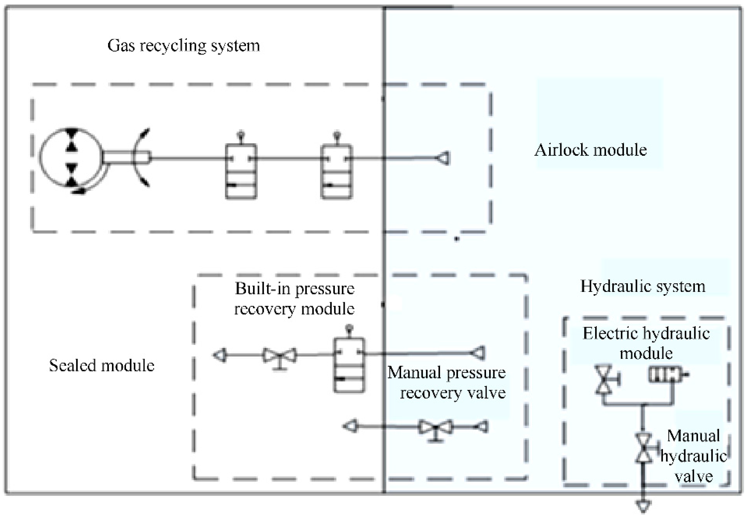
The overall design method of the extravehicular system based on the integrated design of the airlock module and the universal design of different tasks outside the module was proposed to achieve excellent coupling by integrating multiple modules, multiple tasks, diverse working modes, and multi-systems in the space station and to realize the first in-orbit application of gas recycling technology in the field of manned spaceflight in China.
(2)
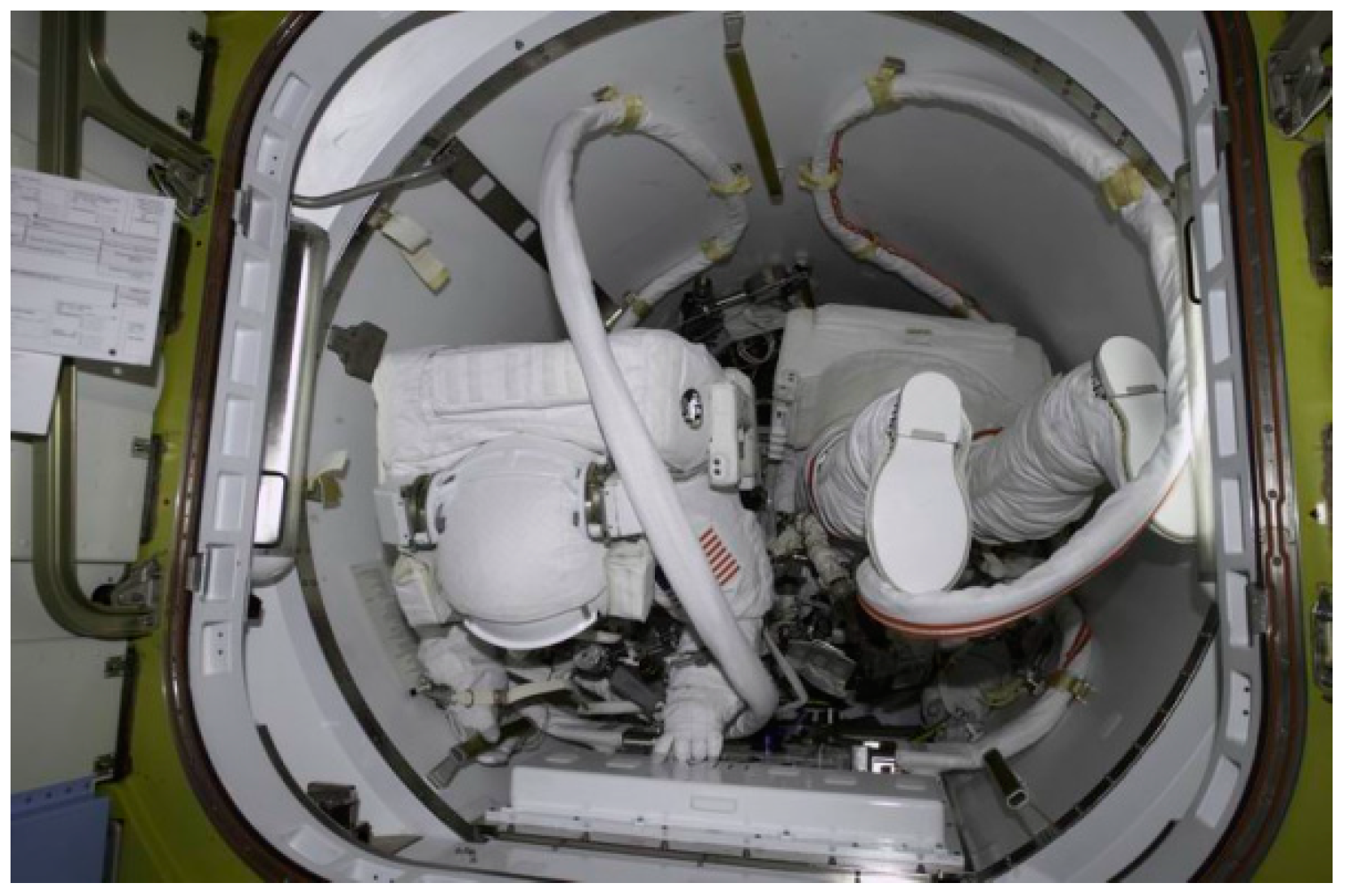
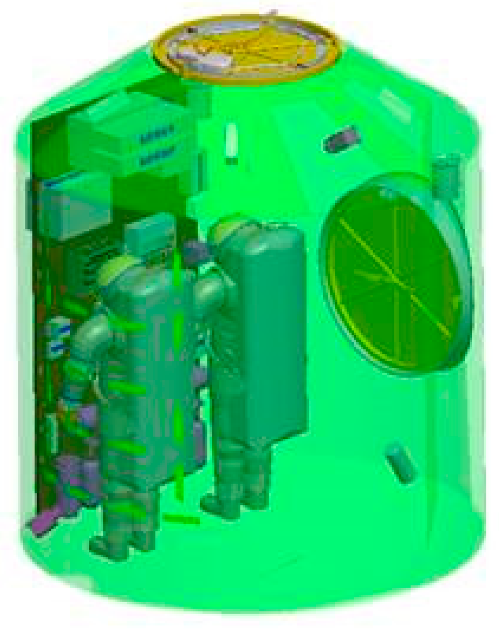
For the first time in China, a ground verification system for the whole process of extravehicular missions has been established, including system-level three-dimensional man-suit-module simulation verification, layout verification for passing the airlock under the compact space constraint in the spacecraft, safety verification of the whole process of extravehicular missions, low-pressure environment verification, operability verification under the microgravity environment, etc. It has solved a series of problems, such as spatial constraints, support constraints, the large difference between space and the Earth, and high safety requirements for astronauts on extravehicular missions.
(3)
A fast transfer method combining the transfer of astronauts by manipulators and the autonomous transfer of astronauts was proposed to solve the three major problems of large-scale transfer of astronauts across modules, fixing at working points, and transfer of maintenance equipment under the given time constraints of multi-module and multi-task extravehicular working points.
(4)
The load requirements of the auxiliary device applicable to the requirements of China’s extravehicular service interface were formulated to meet the load bearing requirements of the module body and auxiliary device during the astronaut’s transfer process, the load’s operation process, and the pressure relief/recovery process, as well as the operating force requirements of the operating equipment. It was ensured that the astronaut could operate the equipment properly by using the force exerted by the extravehicular spacesuit.

4.1. System Design of Airlock Modules

The airlock module serves as a transitional compartment for astronauts to move from the pressurized cabin environment to the vacuum of space [9]. The primary functions of the airlock module include providing space and assistive devices for two astronauts to don and doff their extravehicular suits, as well as depressurizing the vacuum to verify the astronauts’ readiness to open the airlock door and enter space. Currently, there are two active spacecraft that can support extravehicular missions. One is the China Space Station, developed by China. The other one is the International Space Station, which was developed by countries led by the USA. There are two airlock modules on the International Space Station. One is the joint airlock module, Quest, and it supports spacesuits from Russia and the USA (see Figure 4 and Figure 5 for configuration). The other one is the airlock, Zvezda, which only supports Russian spacesuits. The area of the airlock module, Quest, is about 4.25 m3 and can only allow two astronauts with spacesuits to pass through. And in the airlock module, the astronaut cannot dress or undress the spacesuit, and the equipment cannot pass through it.
The airlock modules in various spacecrafts supporting the EVA of astronauts are shown in Table 1. The space station uses dedicated airlock modules for a long time in orbit, hanging on the external body or carried in the lab module, but their position is located at the end of the sealed module. The volumes of the airlock module at the International Space Station (ISS), China Space Station, and SZ-7 are 4.5 m3, 10 m3, and 4.4 m3, respectively [10].
The Chinese Space Station is equipped with the following two airlock modules: the core module and the lab module. For extracurricular missions on the ISS, the astronaut can wear a Russian or American spacesuit for EVA. The pressure mechanisms for them are different (30 kPa for American extracurricular spacesuits and 40 kPa for Russian extracurricular spacesuits). The International Space Station can only support the extravehicular service of the US and Russian spacesuits. China Space Station applied one unified Chinese extracurricular spacesuit. Therefore, the two airlock modules in the China Space Station can support all the EVA of astronauts with various spacesuits to carry out the EVA and have the function of fault reconstruction.
During the EVA process, the onboard support equipment at every node in the module remains powered up. When the airlock module, Wentian, has extreme conditions that cannot be recovered, the astronaut can safely return to the sealed module through the node module of the core module. The node module of the core module measures 8 ft × 7 ft × 8 ft. It can provide a space of 7.4 m3 for astronauts. The airlock module of the lab module of Wentia measures 10 ft × 8 ft × 8 ft and can provide a space of 10 m3. The airlock module can allow astronauts to dress or undress extravehicular spacesuits and pass the airlock, and it can also allow standard-sized equipment to pass the airlock. The airlock module has a large space and can be used as a place for assembly, inspection, testing, storage, and dressing of extravehicular suits. The materials in the airlock module must meet the fire prevention requirements below 27% oxygen concentration and should be able to withstand the vacuum environment. The electronic products supporting the EVA task must work normally under vacuum conditions.
In this paper, we considered the spatial requirements for the dress/undressing of spacesuits (the external dimensions are 6.6 ft × 2 ft × 3.3 ft) and the passing of astronauts and standard-sized equipment (the external dimensions are 2 ft × 2.3 ft × 2 ft) through the airlock. The dynamic three-dimensional model was established for the data of the body envelope, transfer freedom of legs, knees, and ankles of the Chinese astronauts wearing the space suit, and the astronaut’s field of view (see Figure 6). The digital simulation was carried out with real operation driving data, and the space design and verification for the assembly, inspection, testing, storage, and dressing place of the extravehicular spacesuits were completed by using the method of extravehicular spacesuit verification in the real module of the space station.

4.1.1. Opening Force for the Door of the Airlock Module

The airlock module of the space station adopted the design of the driving device for door opening. The hand-pull door opening method of the Shenzhou VII astronaut under the pressure of a 2 kPa module was improved over the pressure relief driving method. When an astronaut opens the door, he or she can use a driving device to open the module door by 0.5 feet, reducing the cabin pressure from 2 kPa to less than 100 Pa in 10 s and the opening operation force from 500 N to less than 100 N. Figure 7 shows the door opening of the airlock module for astronauts in orbit.

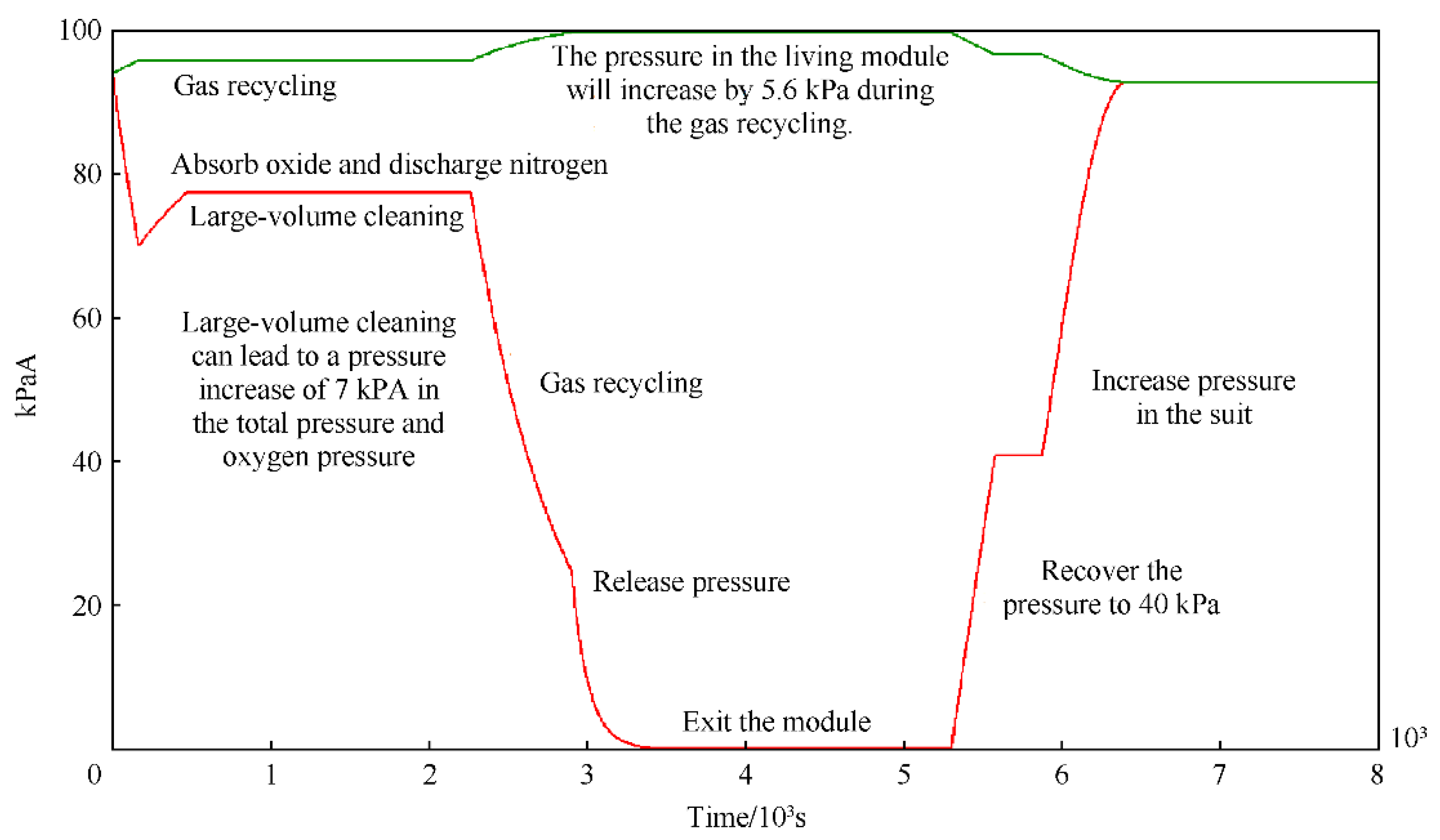
4.1.2. Pressure Relief/Recovery System

The relief/recovery function of the airlock can release or increase the pressure in the module to meet the dual-direction transition between pressurized conditions and vacuum conditions in the module. In this period, the airlock can support the astronaut in dressing or undressing spacesuits and protect their safety [11].
In order to solve the safety problem of the pressure-relief system and the pressure-recovery system in the sealed module, the space station has developed an independent method for the relief and recovery functions of pressure by designing the following two systems: the pressure relief system and the pressure recovery system. The composition of the pressure relief/recovery system of the airlock module is shown in Figure 8. Firstly, the volume of the airlock module was calculated by the fluid dynamics calculation software “Fluent”, and the time and rate of pressure relief in the airlock module were predicted (within 30 min, the pressure (94 kPa) in the airlock module was lowered to 2 kPa, where the astronaut could begin to open the module door). The vacuum tank was used to carry out the pressure relief test on the real module so as to realize the optimization of the index and verify the rationality of the design. Secondly, the oxygen concentration in the node module was controlled in advance before the astronaut passed the module in order to prevent the fire safety problem caused by the increase in oxygen concentration in the node module during the oxygen uptake and nitrogen removal of astronauts. The test results show that the oxygen concentration can be effectively reduced to 25% by using the pre-control method (the highest oxygen concentration in orbit as measured by the oxygen sensor). Thirdly, the astronauts will carry out multiple EVAs every year due to the long-term in-orbit operation of the space station. In order to save gas on the station and reduce the material loads in the cargo spacecraft, the pressure relief/recovery system in the space station is required to have the function of gas recycling. During pressure relief, the gas in the airlock module is pumped to the main module by means of atmospheric pressure transfer. During pressure recovery, the main module is used to realize the recycling of some gas in the airlock module, so as to save gas resources. The real in-orbit gas recycling rate is 73.4%, and about 124 kg of gas is saved per year.
Figure 9 shows the distribution of gas pressure in the airlock module with time during the first extravehicular mission of the Shenzhou XII crew. The pressure relief and recovery systems support the pressure relief of the airlock module from the normal module pressure to 2 kPa in 40 min during the astronaut’s passage. After the astronaut returns to the node module, the pressure in the module is recovered from the vacuum to the same pressure as the life control module within 30 min. The whole relief and recovery process is matched with the requirements of the pressure system of the extravehicular spacesuit. It is proven by the actual missions that the pressure relief/recovery system of the two airlock modules of the space station is qualified.

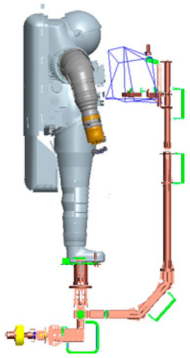
4.2. Extravehicular Transfer Technologies for Astronauts

The rapid transfer method combining manipulator transfer of astronauts and autonomous transfer of astronauts was adopted in extravehicular missions of the space station. It solves the following three major problems for missions at multiple working points across the module sections within fixed time in a single extravehicular mission: large-scale transfer of astronauts; fixing at the working point; and transfer of maintenance equipment. The system optimization design of astronauts’ extravehicular transfer is realized, and the astronaut with spacesuits can be returned to the airlock module at any position outside the module under the condition of failure.

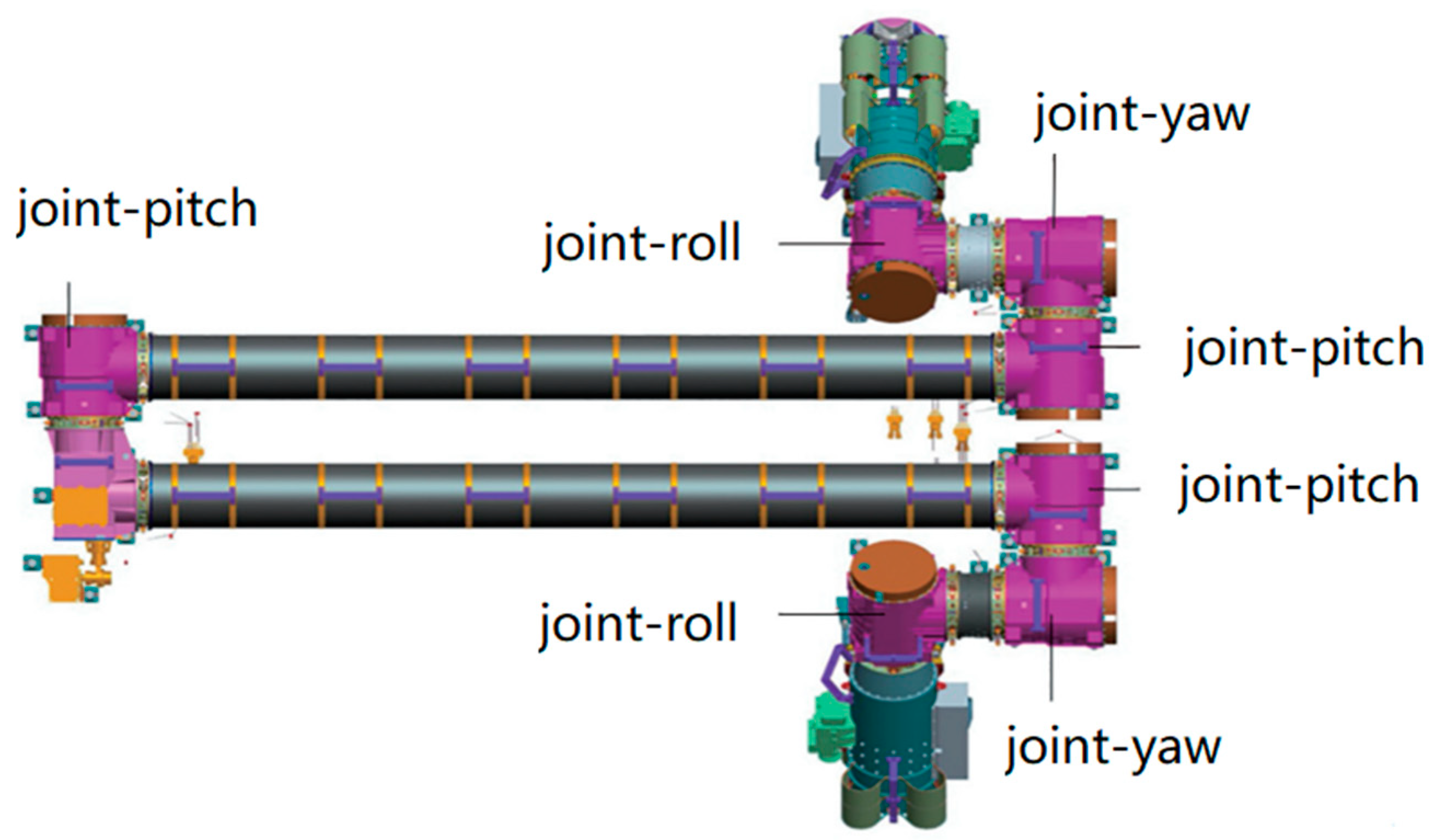
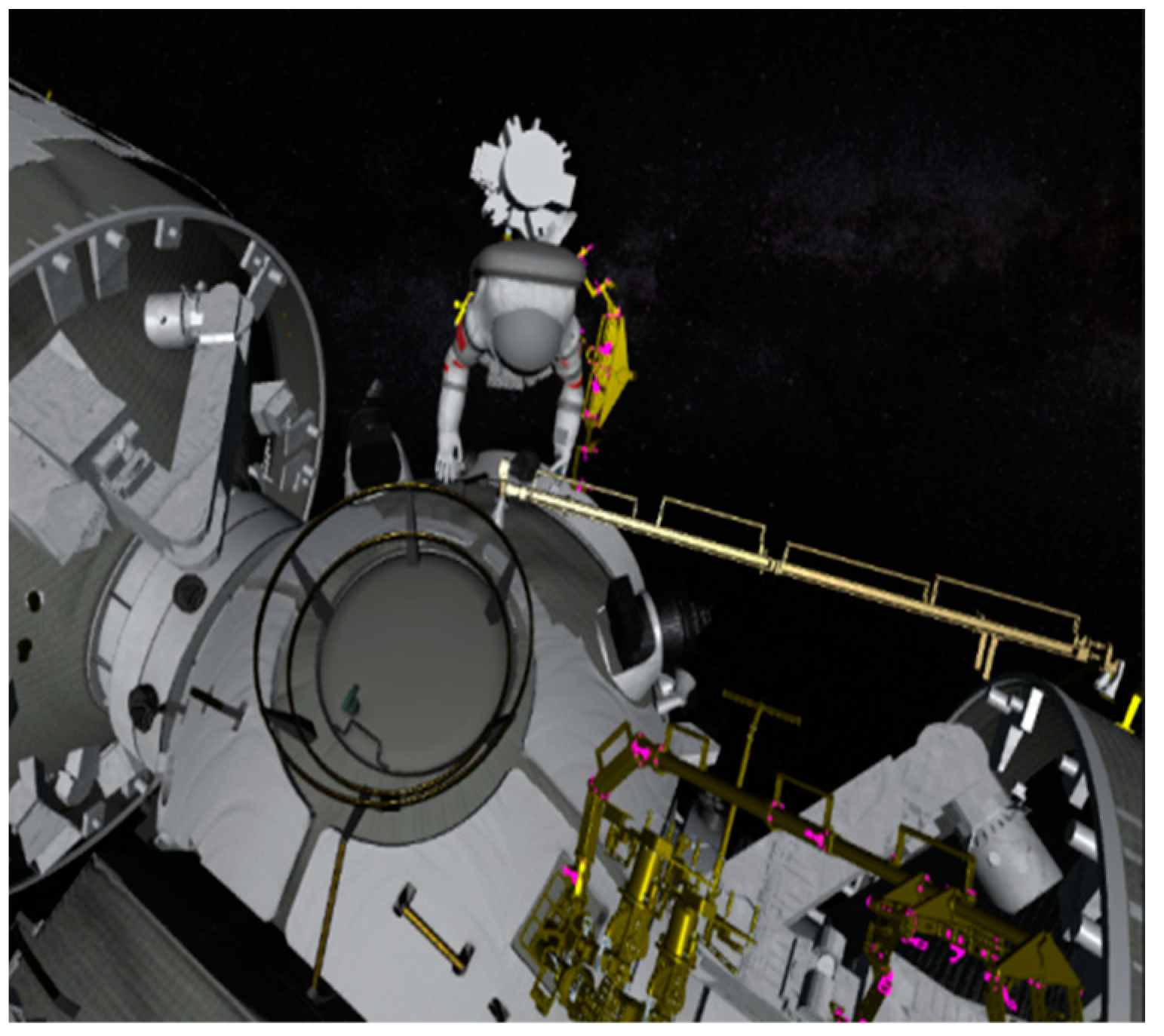
4.2.1. Manipulator-Supported Transfer and Operation

When astronauts work outside the module, they need to use the extravehicular foot stops to fix their feet so as to force the hand to operate the equipment. For all the extravehicular operation projects of the space station, the astronauts should be transported to the workplace by the manipulators, and the foot stops on the manipulators are used to fix the feet of the spacesuit. The astronauts use their hands to operate electric tools or their bare hands to carry out maintenance tasks at the workplace. This method has a wide range of activities and can reach the workplace quickly. At the same time, the manipulator can carry ORU (orbital replacement unit) and maintenance tools, which is convenient and efficient. The relationship between astronauts, manipulators, and related equipment is shown in Figure 10 and Figure 11.
According to the requirements for the extravehicular transfer mission of the Chinese astronauts, the manipulator system on the Chinese Space Station is a crawling dual-arm combination and cooperative system, combining a 7-degree-of-freedom large manipulator in the core module (referred to as a large manipulator) and a 7-degree-of-freedom small manipulator in the lab module (referred to as a small manipulator). Among them, the large manipulator of the core module has a large operating radius and strong load capacity, which can independently support astronauts to carry out operational tasks outside the module, Tianhe (see Figure 12 for details). The small manipulator of the lab module has high operating accuracy but a small operating radius and can independently support astronauts to carry out operational tasks outside the modules, Tianwen and Mengtian (see Figure 13 for details). When the space station completes the organization and construction of the core module, lab module I, and lab module II, the large manipulator and small manipulator can support the astronauts to carry out a wide range of transfer tasks (see Figure 14). The astronaut can successfully complete tasks related to the loading, operations, and unloading of the manipulators. Extracurricular missions, with the support of manipulators, can be continuous and feasible.

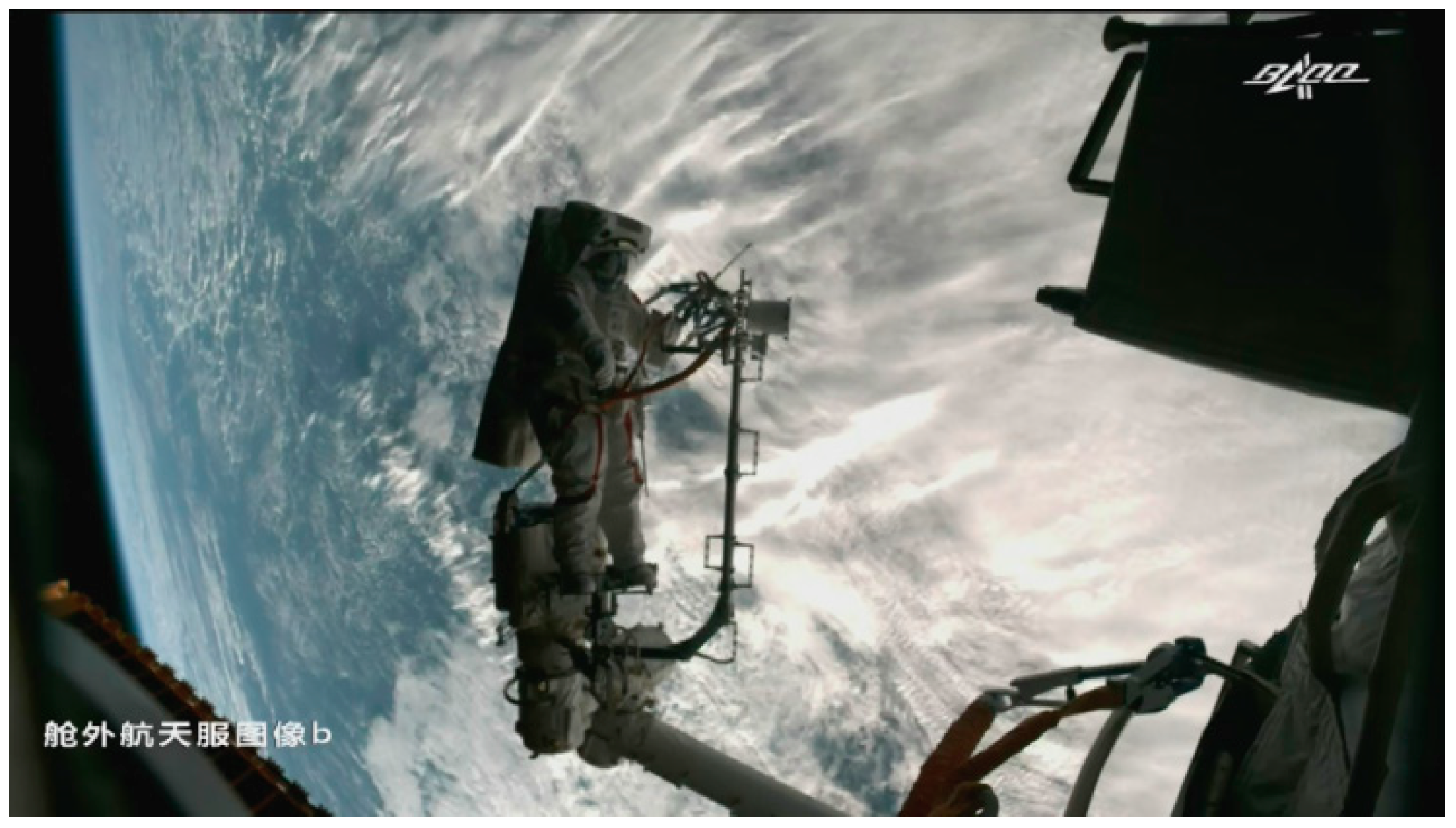
4.2.2. Autonomous Transfer and Operation

In order to ensure the safe completion of extravehicular autonomous transfer of astronauts, the extravehicular autonomous transfer path of the space station covers all operating points and manipulator adapters to ensure that all operating points outside the module can be reached and to ensure that astronauts can transfer to the airlock module when any failure occurs in the facility. The EVA handrails are set on the surface of the space station (see Figure 15), which makes it convenient for astronauts to move and provides position limitation when wearing spacesuits for extravehicular activities. And the handrails have a tether connection point, which can adapt to the use of the tether device hook. Figure 16 shows the autonomous transfer of astronauts outside the aircraft using handrails.
In order to solve the problem that the astronauts cannot transfer across the module due to the height difference of the outer diameter of each segment of the aircraft in the space station, the space station is arranged with a design so that astronauts can make bridges between the transfer paths of the astronauts among three modules to support the autonomous transfer and emergent return tasks (see Figure 17).

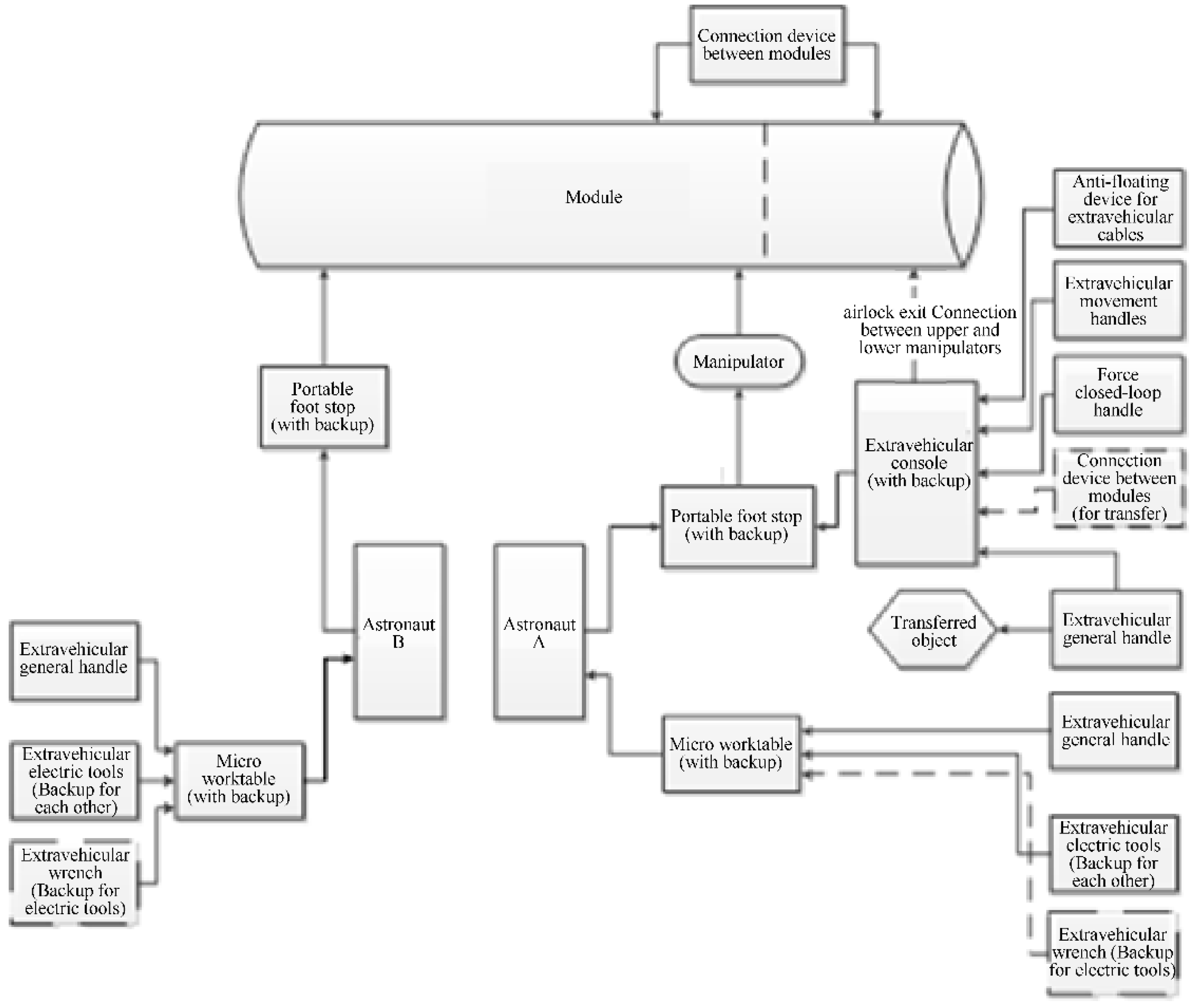
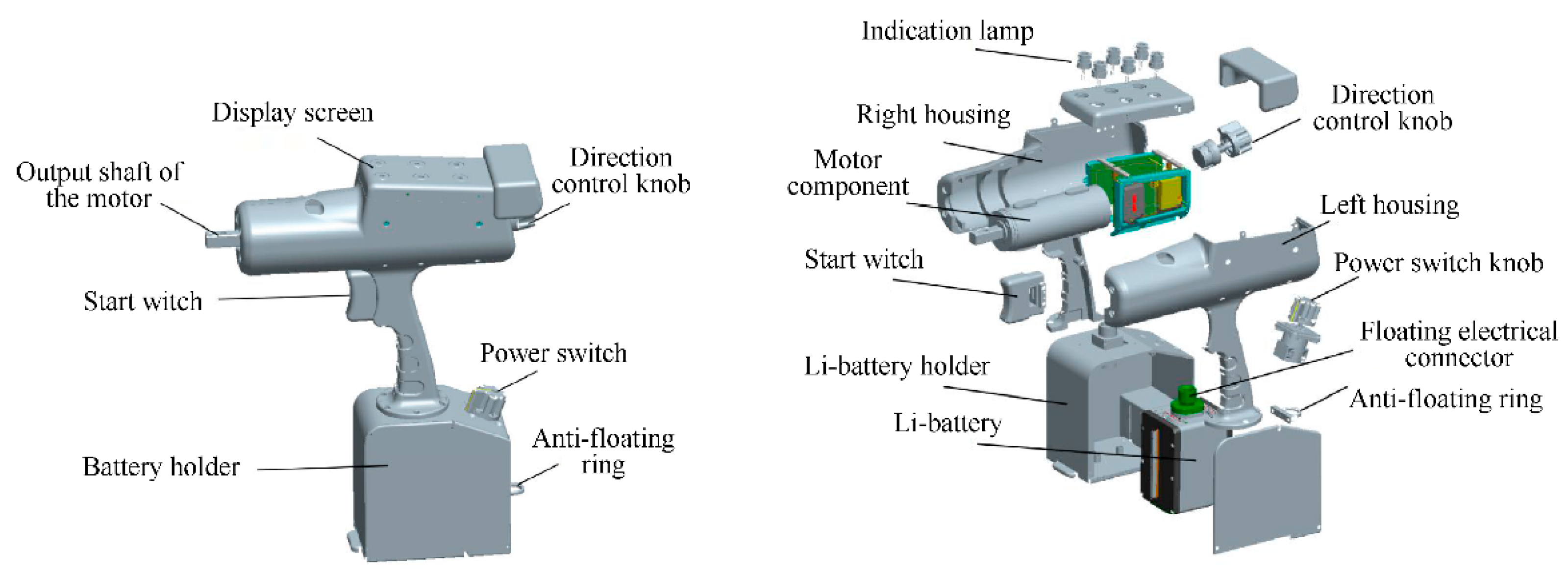
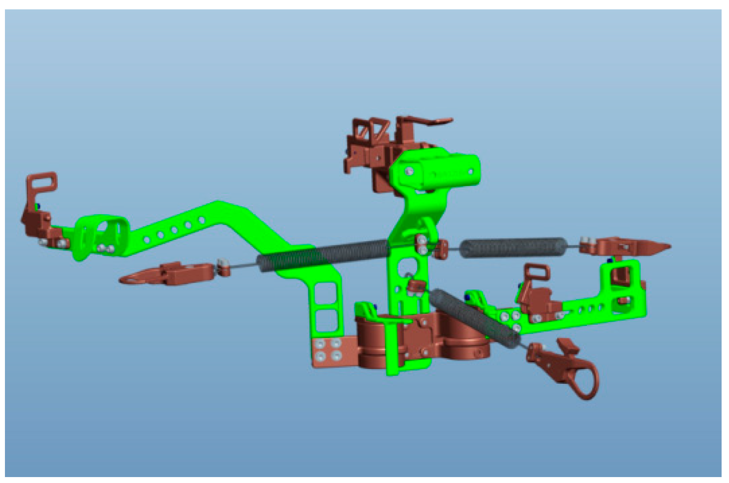
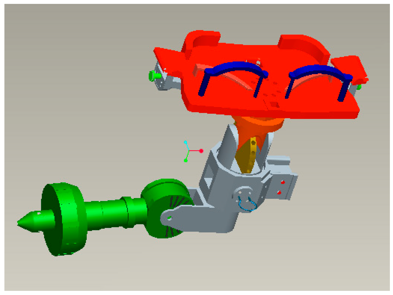
4.3. Design of Extravehicular General Facilities

The EVA in the space station is realized by a series of activities such as body transfer, material transfer, pose adjustment, body fixation, and operation. Due to the influence of microgravity and the limitation of vision and athletic ability of the extravehicular human service system in space, a simple human service system cannot complete any of the above activities, and they must be realized by using auxiliary facilities. Due to the complexity of the space station’s EVA, the use of support facilities directly affects the efficiency of EVA and the load of astronauts. Therefore, in the face of multi-tasking and complex EVA, the space station system has been designed with a set of systematic, efficient, and highly reliable general facilities.
The general facilities for the space station’s EVA fully consider the combined application of products and minimize the matching under the premise of satisfying reliable backup. The combined application relationship is shown in Figure 18. Among them, the extravehicular power tools are electromechanical products, and the rest are mechanical products.
Tools and devices that assist astronauts in performing extravehicular tasks on the space station are mainly long-term recycling, including extravehicular power tools, miniature workstations, portable joint foot stops, and extravehicular consoles. The electric tool is controlled by the motor and uses the battery as the energy source (see Figure 19). It can provide torque to fasten and disassemble screws, and operators can also set the torque, speed, and number of turns of rotation. It can facilitate the maintenance operations of astronauts and reduce the workload of astronauts’ maintenance operations.
The micro-workstation is installed in front of the astronaut extravehicular spacesuit (see Figure 20). It can be installed on the extravehicular spacesuit to fix the power tools and other gadgets so that the astronauts can carry the operating tools during EVA to perform the task.
The articulated foot stop is connected to the manipulator or the space station surface via the slot and is installed on different stations according to the task requirements (the external dimensions are 2 ft × 1.9 ft × 1.1 ft) (see Figure 21). When the astronaut is fixed to the foot stop for tasks, the foot stop can provide a rigid limit for the astronaut so that it can work stably.
The extravehicular console provides a space interface for the long-distance transmission equipment on the manipulator (the external dimensions are 5 ft × 1.5 ft × 1.1 ft) (see Figure 22). After the extravehicular console is mounted on the portable foot stop, it can rotate around the axis by ±90°. The astronaut can use the combination according to the actual situation.

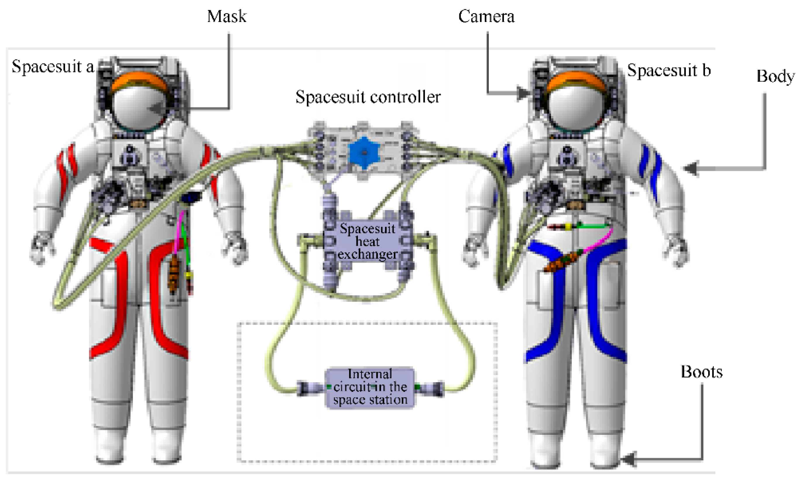
4.4. Support Technologies for Extravehicular Spacesuits

The extravehicular spacesuit applied by China’s space station is equipped with a system to independently support astronauts on extravehicular missions. The astronaut can communicate information with the space station and ground controllers via wireless systems during extravehicular missions. The respiratory system and the heat dissipation system can support the space station’s demand and meet requirements for the survival and work of astronauts during EVA. Resources for the extravehicular spacesuit were provided by the onboard equipment of the space station.
The extravehicular spacesuit system of the space station mainly includes an extravehicular spacesuit and extravehicular support equipment for the suit, as shown in Figure 23. Extravehicular spacesuits ensure the safety of astronauts who carry out missions outside the space station. Onboard equipment provides support by using thermal, electrical, and information systems for astronauts to pass through the airlock while wearing extravehicular spacesuits. The extravehicular spacesuit for astronauts to leave the module includes a mask and a camera in the suit. When astronauts perform extravehicular tasks, the spacesuit can provide support for pressure protection and thermal protection under extravehicular vacuum, high-low temperature alternating conditions, environmental control and life insurance, information management, voice communication, and camera support. The EVA support facilities can support the tasks of astronauts with the extravehicular spacesuit during the entry and exit of the airlock module, which is composed of the clothing console, the clothing heat exchanger, and the internal circuit of the space station.

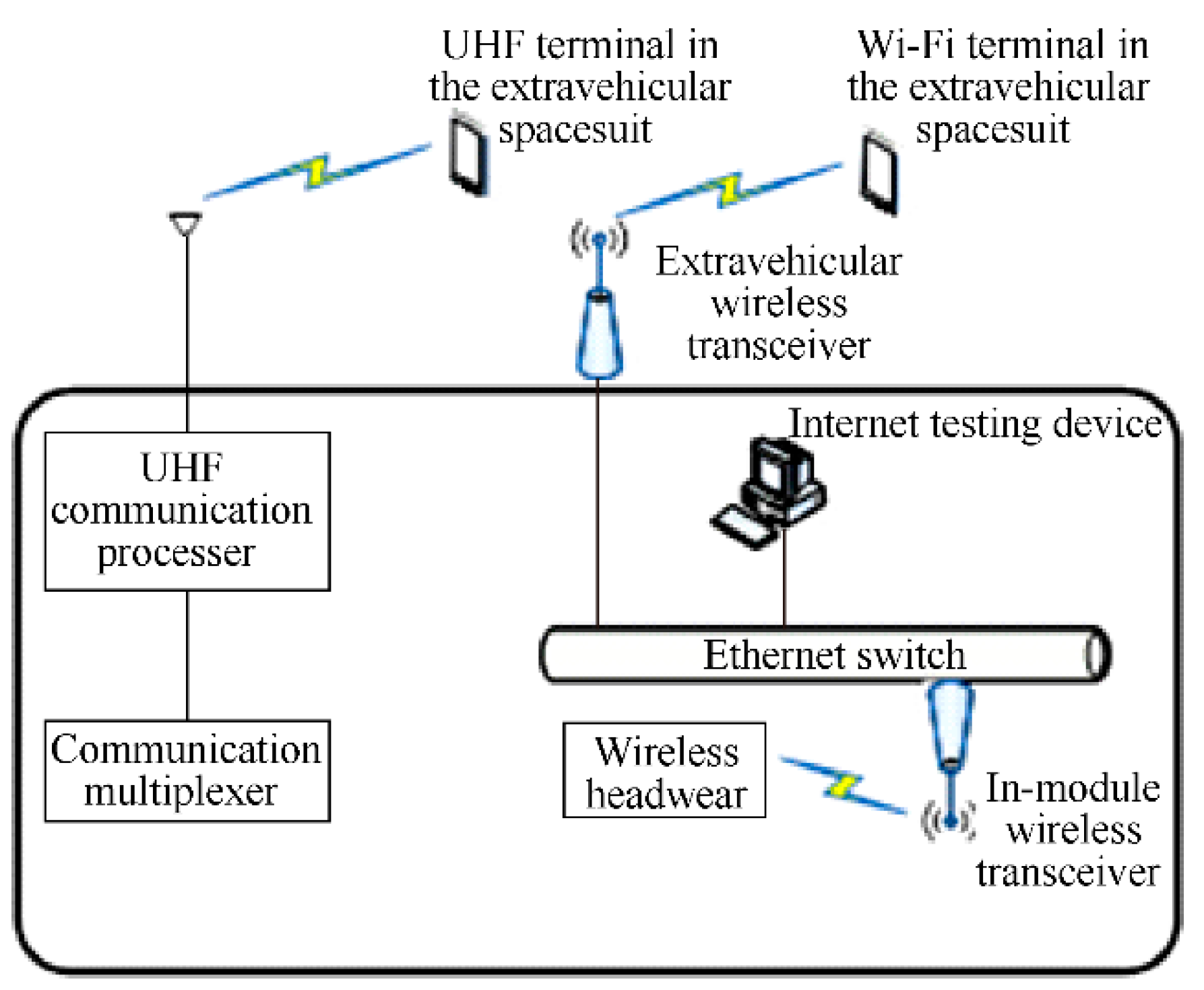
4.5. Support Technologies for Communication, Lighting, and Monitoring of EVA

4.5.1. Design of Communication Systems

The extravehicular communication system of the space station mainly includes wired communication, UHF wireless communication, and Wi-Fi wireless communication. The wired communication (umbilical wire) and UHF wireless communication can realize the transmission of two-way voice and physiological telemetry data among extravehicular astronauts, in-module astronauts, and ground units and have been verified by the flight mission of the manned spacecraft, Shenzhou VII.
Compared with the Shenzhou VII, the extravehicular missions on the space station have a larger information transmission range and a faster transfer speed for astronauts on the manipulator. Therefore, after opening the door, the astronauts disconnect the wired communication and use wireless communication throughout the extravehicular mission. The extravehicular communication connection relationship is shown in Figure 14. In order to ensure the multi-channel downlink of information transmission, the image of the extravehicular spacesuit’s camera is transmitted into the sealed module and the downlink control center. The space station adopts a wireless communication system based on Wi-Fi technology. Figure 24 shows the connection between the extravehicular space suit and onboard support equipment. The space station is equipped with three Wi-Fi antennas and three UHF antennas outside each of the three modules. By using simulation analysis, the effective communication area of the space station antenna can be determined by the signal coverage of the area where the extravehicular astronauts are located. The in-orbit measurement shows that the image and extravehicular spacesuit data are continuous during the astronaut’s extravehicular transfer. And the extravehicular signal ensures smooth communication during the astronaut’s transfer to the operation area.

4.5.2. Design of Camera Systems

The two airlock modules of the space station are equipped with real-time monitoring cameras to capture the process by which astronauts pass through the airlock. The extravehicular camera monitoring system is equipped to track the extravehicular activities of astronauts and provide monitoring means for the extravehicular operation objects. Figure 25 is a simulation of the external surveillance field of view and lighting effect; Figure 26 shows the actual results. Cameras to support astronauts on extravehicular missions include panoramic cameras for 360° adjustment and panoramic cameras for spot observation of critical equipment, as well as a 360° rotating cast light to supplement the camera’s illumination.

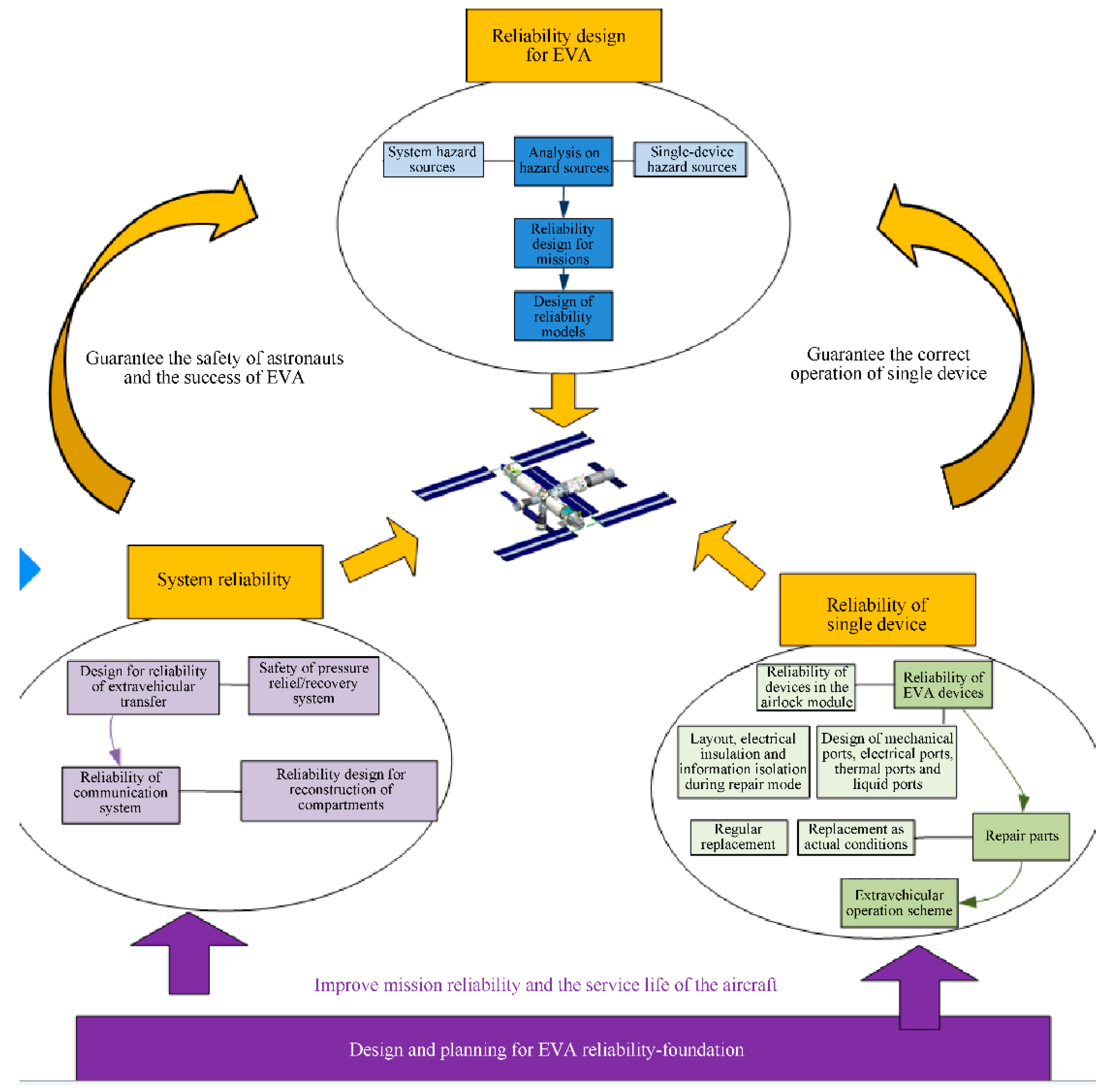
4.6. Design and Implementation of the Safety System for EVA

In the process of astronauts’ extravehicular missions, there will be some hidden dangers to the safety of astronauts and extravehicular spacesuits, such as the collision of micrometeoroids, the fire and pressure loss of the sealed module, and the failure of the pressure relief/recovery system. And the surface voltage of the aircraft can be higher than the safety voltage of the extravehicular spacesuit. In the space station system, an extravehicular reliability verification and evaluation system suitable for the requirement for EVA under the conditions of China’s multi-mission, multi-module combination, and repairable spacecraft was constructed. An evaluation solution was proposed to guarantee the EVA’s safety. The damage to extravehicular equipment in the long-term operation of the space station was quantified. When the in-orbit extracurricular repairable equipment is found to be faulty via ground telemetry and the equipment cannot be reset via the in-orbit fault handling plan, the ground office confirms the fault of the equipment, and the extracurricular task needs to be carried out. And the quantitative evaluation of the reliability of the spacecraft during the development stage and in-orbit operation was realized. It provides a basis for mission decision-making. From single machine design, module system design, and process emergency design, different levels of hazard sources were identified, and the reliability guarantee for the module system was formulated (see Figure 27).

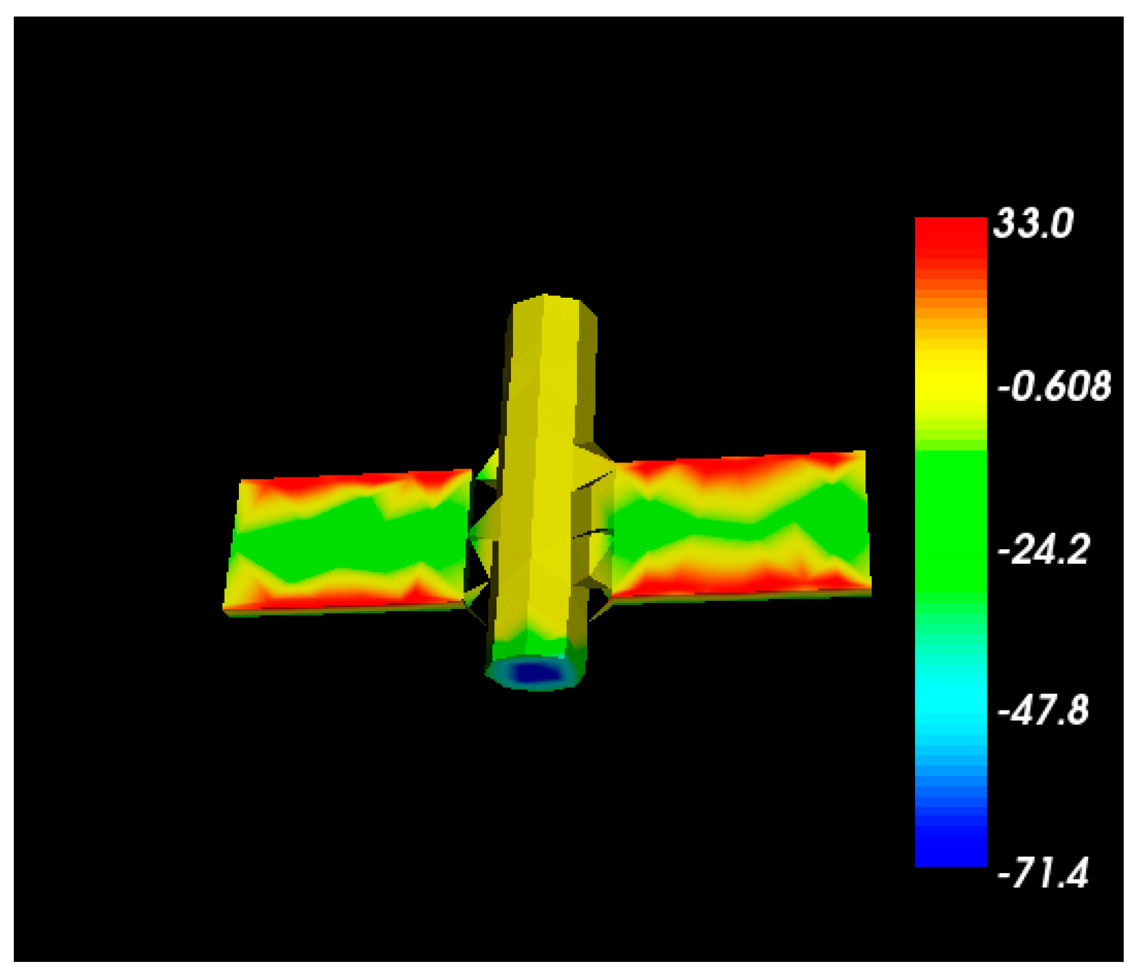
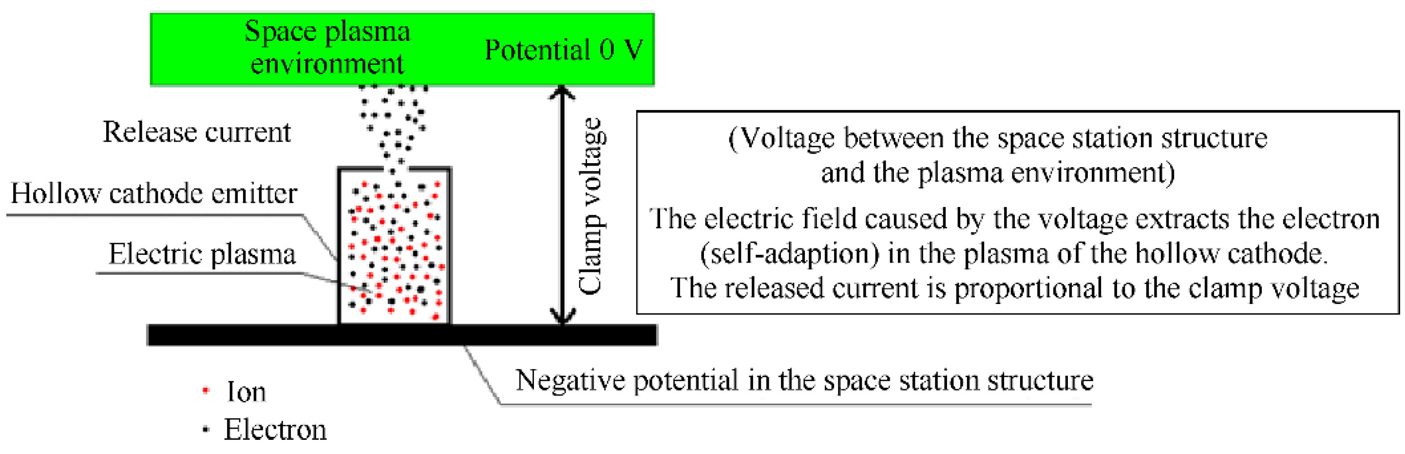
4.6.1. System Design for Active Potential Control in the EVA Space Environment

There is a potential difference between the in-orbit space station structure and the space plasma environment. In order to ensure the safety of astronauts’ EVA, the space station system adopts the protection strategy by using an active potential control system to fully ensure the safety of astronauts’ EVA [12]. In the simulation analysis of the core module of the space station (see Figure 28), the worst plasma environment density at 1012/m3 was adopted. The simulation analysis was carried out according to the given solar array structure and module structure of the core module, as well as the maximum operating voltage at 114 V of the solar array. The analysis results are shown in the figure below. According to the simulation analysis, the core module structure potential is −71.4 V.
The EVA working time of astronauts is generally 6 h, while the orbit period of the space station is 91 min [13]. There are many times of entering and leaving the Earth’s shadow. Related detection results show that there will be a very obvious fast-charging effect when the international space station is out of the shadow, and the structural potential can be as high as −80 V. Affected by the structural potential of the space station, a space station–astronaut–plasma circuit is formed to generate a discharge current.

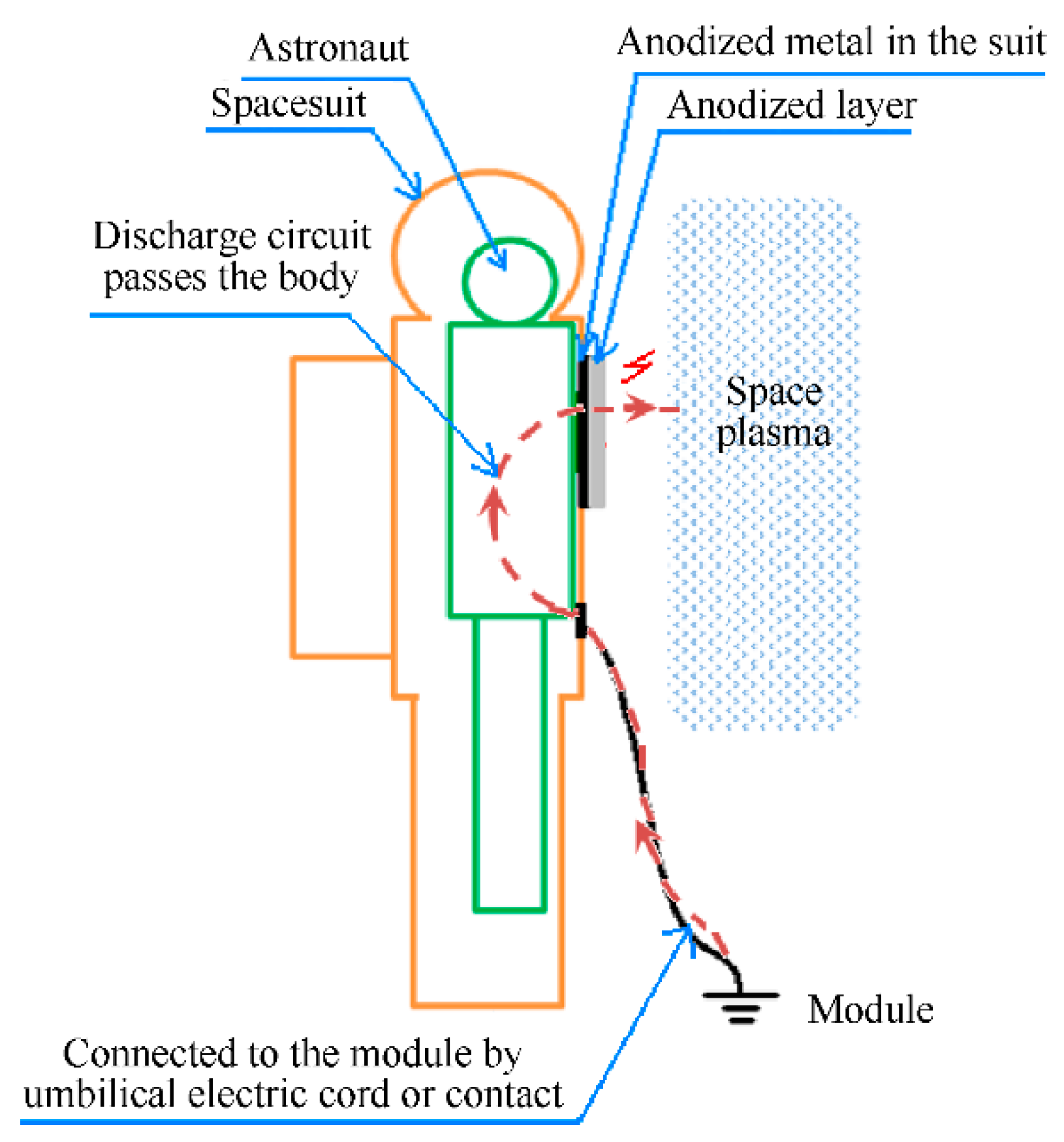
4.6.2. Discharge Circuit (Space Station–Astronaut–Spacesuit–Plasma Environment)

As shown by the analysis of the equipotential state of the circuit (space-spacesuits-astronaut), the anodic layer on the extravehicular suit makes it easy to cause discharges. When the following conditions are met at the same time, the discharge path of the circuit (space station–astronaut–spacesuit–plasma environment) will occur, as shown in Figure 29 [14].
(1)
There are exposed surface anodized metals on the surface of the spacesuit;
(2)
There is no insulation protection between surface-anodized metal and astronauts;
(3)
Astronauts are in contact with surface anodized metal and module structure at the same time (connected to the module by umbilical electric cord or contact);
(4)
The discharge threshold of the surface anodized metal is lower than the structure potential of the space station.

4.6.3. Active Potential Control System

The system controls the structural potential of the space station via a hollow cathode emitter. The hollow cathode emitter is mainly composed of a hollow cathode, a gas-path quick-plug assembly, a cathode gas-path assembly, and other components.
The hollow cathode emitter ionizes the internal xenon gas into the plasma. Under the action of the electric field between the space plasma environment and the space station structure, the electrons in the plasma inside the cathode are extracted to achieve the purpose of controlling the potential of the space station structure (potential of the space station structure relative to the space plasma environment), as shown in Figure 30. According to the measured data of the core module in orbit, the potential difference of the module before and after the active potential system is turned on is reduced from 70 V to about 15 V, which meets the design requirements of the extravehicular spacesuit system.

4.7. Verification Technologies for EVA on the Ground

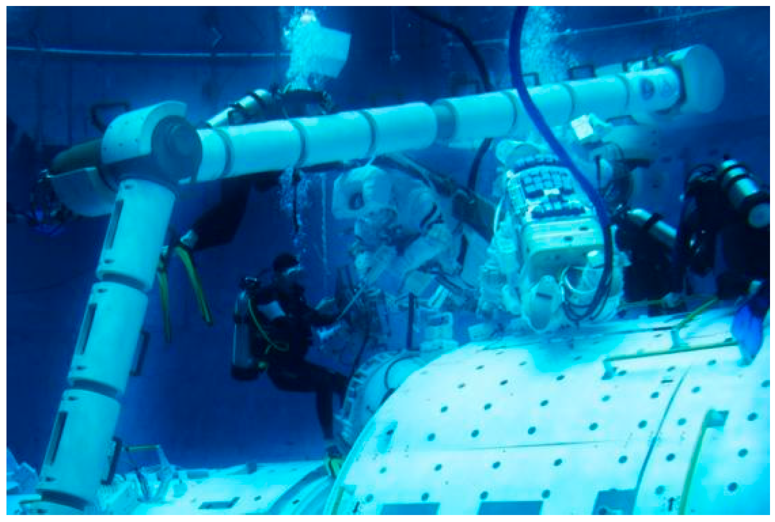
4.7.1. Simulation Verification under Microgravity

In the study of the microgravity environment of extracurricular missions, there are two means as follows: neutral buoyancy in channels and parabolic flight of large aircraft. Short-term tests can be carried out in the parabolic flight of large aircraft, while for long-term multi-task EVA verification, neutral buoyancy in tanks has the characteristics of realistic test results, easy construction of test scenarios, and low long-term use costs.
The underwater test module, underwater manipulators, and underwater load devices were put in the simulated weightless tanks to carry out typical verification for EVA. Figure 31 is a picture of the verification for the exit of astronauts from the airlock under water. The simulation was used to verify the extravehicular support capability of the space station platform related to the weightless environment, the platform maintenance and repair operation, and the operation of extravehicular load equipment (see Figure 32). Large mass objects were configured to verify the transfer control ability of the large mass object by using the air flotation platform.
In underwater verification, the buoyancy of water is balanced by a counterweight to achieve zero gravity. Materials heavier than the density of water, such as metal materials, can be used with plastic buoyancy blocks, and materials lighter than water, such as lead blocks, are used to balance the pressure.

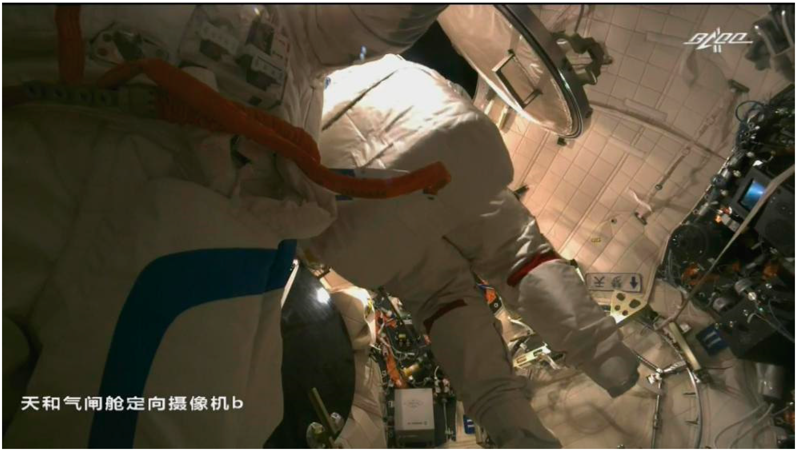
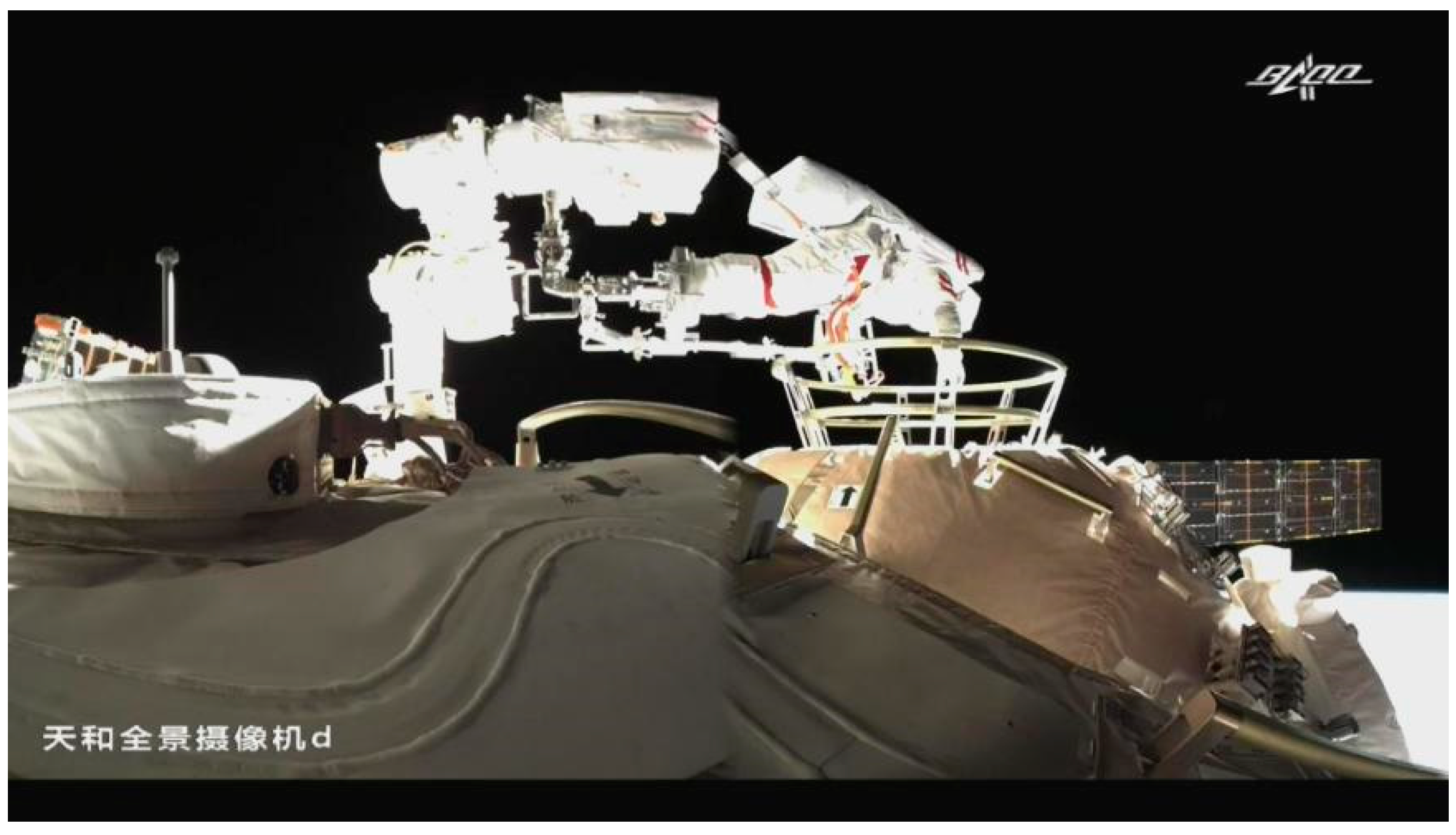
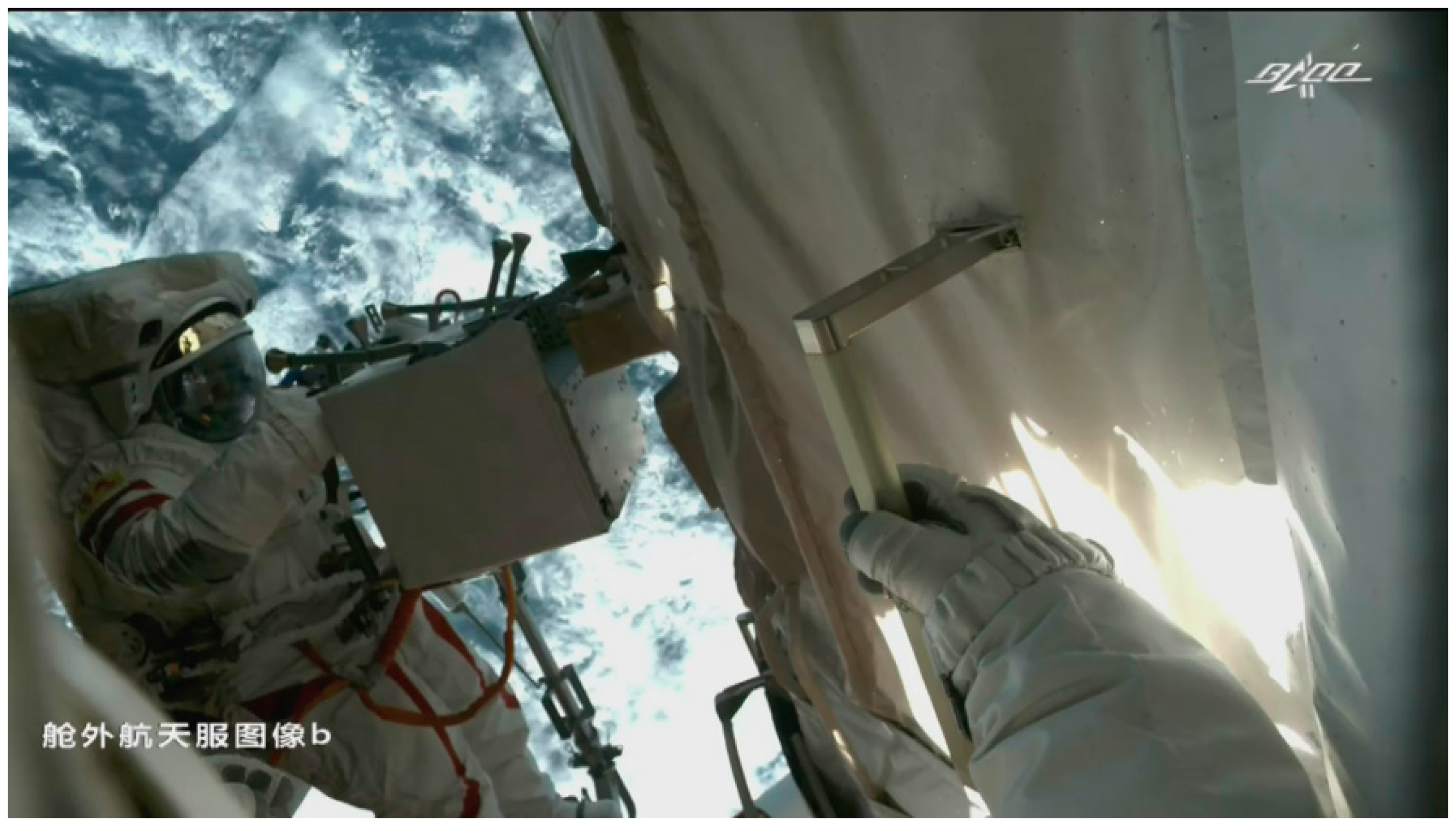
4.7.2. In-orbit Flight Verification

The in-orbit extravehicular installation tasks to expand the pumps were conducted by the Shenzhou crew and studied to verify the design compliance of items (see Figure 33 and Figure 34: the operation ability of the astronaut and the spacesuit; the mechanical installation, fastening, and removal of platforms in the space station when the fixing device is linked; the installation and removal of cables (plugs); and external marking (Chinese marking of products and connectors)).

4.7.3. Future Works

According to the current status of in-orbit missions and the requirements of subsequent missions, the development direction of EVA systems and technologies at the China Space Station mainly includes extravehicular supporting device automation technology and large-scale application technology for operating objects. The automation technology of supporting devices is mainly aimed at the current extravehicular mission process. A large amount of space operation time for astronauts is spent on the assembly of the foot limiter and the operation platform at the end of the manipulator, while less time is spent on the effective maintenance of extravehicular equipment. For the subsequent space station system, the developers should be devoted to the development of remote-controlled manipulator systems to complete the installation of supporting devices so that astronauts can load the manipulator after exiting the module. Thus, more extravehicular time and astronauts can be used for extravehicular maintenance operations. In addition, the safe maintenance and replacement of large equipment, such as extravehicular solar wings, is also a technical method that needs to be solved in the follow-up of extravehicular missions of the space station.

5. Features and In-Orbit Application Status of Main EVA Technologies

The configurations of extravehicular system design at the Chinese Space Station, Mir, ISS, and Shenzhou VII are listed in Table 2. By comparing the data, it is obvious that the functions of the China Space Station to support passing through the airlock, extravehicular transfer, and other tasks are comparable to the world-leading level.
The complex EVA technologies of the space station are the guarantee for the successful completion of the assembly and construction of the space station and long-term flight missions in the subsequent 15 years. It provides flight test data and accumulates valuable experience for astronauts to carry out extravehicular missions in a combination of multiple spacecrafts. The research results can be directly used in the subsequent module expansion of the space station, the extravehicular maintenance of the optical module, and the extravehicular installation of extravehicular scientific experimental equipment. The extravehicular missions of CSS have applied technical breakthroughs and led to the leap-type development of manned spaceflight technologies in China. China has become the third country to master EVA technologies in the world. It can create significant technical value and social benefits. China has fully mastered the EVA technologies of the space station via the EVA flight test.

6. Conclusions

In this paper, we introduced the overall general technologies and implementation technology design of the EVA system on the Chinese Space Station and compared the key parameters with similar foreign technologies. The execution of the first fourteen missions of the China Space Station in orbit shows that the design of the general technologies and implementation technologies of the space station are reasonable. It is beneficial to ensure the complete success of EVA on the space station and has engineering practical value. In the future, with the increasing demand for manned exploration missions, EVA technologies can be applied in more space technology fields.

Author Contributions

Conceptualization, F.A.; methodology, X.L. and Y.X.; software, X.L. and Y.X.; validation, X.L. and Y.X.; formal analysis, X.L. and Y.X.; investigation, X.L. and Y.X.; resources, X.L. and Y.X.; data curation, X.L. and Y.X.; writing—original draft preparation, X.L. and Y.X.; writing—review and editing, Y.T.; visualization, Y.T.; supervision, F.A.; project administration, F.A.; funding acquisition, F.A. All authors have read and agreed to the published version of the manuscript.

Funding

This research received no external funding.

Data Availability Statement

The raw data supporting the conclusions of this article will be made available by the authors on request.

Conflicts of Interest

The authors declare no conflicts of interest.

References

  1. Xiang, W.; Qiao, Z.; Wei, W. System characteristics and prospect of China Space Station. Spacecr. Eng. 2022, 31, 26–39. (In Chinese) [Google Scholar]
  2. Bainan, Z. Starting a new journey for China’s Manned Space Program. Aerosp. China 2021, 9–13. (In Chinese) [Google Scholar]
  3. Yang, H.Y. System design from space laboratory to China Space Station. Spacecr. Eng. 2022, 31, 7–14. (In Chinese) [Google Scholar]
  4. Fan, W.W.; Han, L.; Yang, F.; Wang, H.M. Review of Scientific Research and Application on ISS in 2018. Manned Spacefl. 2019, 25, 271–276. (In Chinese) [Google Scholar]
  5. Shayler, D.J. Walking in Space; China Astronautic Publishing House: Beijing, China, 2007. (In Chinese) [Google Scholar]
  6. Yang, H. Human Spacecraft Technology; Beijing Institute of Technology Press: Beijing, China, 2018. (In Chinese) [Google Scholar]
  7. Zhou, J. Chinese Space Station Project’s overall vision. Manned Spacefl. 2013, 19, 1–10. (In Chinese) [Google Scholar]
  8. Zhu, G. Development on Configuration Technology of China Manned Spacecraft. Spacecr. Eng. 2022, 31, 46–53. (In Chinese) [Google Scholar]
  9. Zhu, G.; Jia, S. The Ground Verification of Spacecraft EVA Functions. Manned Spacefl. 2009, 15, 48–53. (In Chinese) [Google Scholar]
  10. Zhi, S.; Bainan, Z. Research and Development by Shen Zhou-7. Manned Spacefl. 2009, 15, 16–21. (In Chinese) [Google Scholar]
  11. Dajian, H.; Peng, Y.; Shaowei, Y. Mobility management of LEO satellite communication networks. Chin. Space Sci. Technol. 2016, 36, 1–14. [Google Scholar]
  12. Ferguson, D.C.; Craven, P.D.; Minow, J.L. A theory for rapid charging events on the international space station. In Proceedings of the 1st AIAA Atmospheric and Space Environments Conference, San Antonio, TX, USA, 22–25 June 2009. [Google Scholar]
  13. NASA-HDBK-4006; Low Earth Orbit Spoeeeraft Charging Desip Handbook. National Aeronautics and Space Administration: Washington, DC, USA, 2007.
  14. Liang, X.F.; Zhou, D. Influences of surface charging on astronaut EVA and countermeasures. Spacecr. Acecraft Environ. Eng. 2014, 4, 2–31. (In Chinese) [Google Scholar]
Figure 1. Overall structure of the airlock module in Shenzhou VII.
Aerospace 11 00264 g001
Figure 2. An astronaut was exiting the module (taken by an external camera).
Aerospace 11 00264 g002
Figure 3. China Space Station.
Aerospace 11 00264 g003
Figure 4. Joint airlock module, Quest.
Aerospace 11 00264 g004
Figure 5. Internal structure in the joint airlock module, Quest.
Aerospace 11 00264 g005
Figure 6. Space simulation of the airlock module.
Aerospace 11 00264 g006
Figure 7. An astronaut was opening the module door by using the driving handle.
Aerospace 11 00264 g007
Figure 8. Composition of the pressure relief/recovery system in the airlock module.
Aerospace 11 00264 g008
Figure 9. Pressure curve in the module during the EVA process.
Aerospace 11 00264 g009
Figure 10. The compact configuration of the manipulator.
Aerospace 11 00264 g010
Figure 11. A manipulator was transporting an astronaut and related operation devices.
Aerospace 11 00264 g011
Figure 12. An astronaut was working with the help of a manipulator in the module, Tianhe.
Aerospace 11 00264 g012
Figure 13. An astronaut was working with the help of a manipulator in the module, Wentian.
Aerospace 11 00264 g013
Figure 14. An astronaut was working with the joint help of the manipulators.
Aerospace 11 00264 g014
Figure 15. Transfer handrail on the module’s surface.
Aerospace 11 00264 g015
Figure 16. An astronaut was autonomously moving by using handrails.
Aerospace 11 00264 g016
Figure 17. An astronaut was building a bridge between modules.
Aerospace 11 00264 g017
Figure 18. Combined application of general facilities in the space station.
Aerospace 11 00264 g018
Figure 19. Structure of extravehicular electric tools.
Aerospace 11 00264 g019
Figure 20. Extravehicular micro-workstation.
Aerospace 11 00264 g020
Figure 21. Articulated foot stop.
Aerospace 11 00264 g021
Figure 22. Extravehicular console.
Aerospace 11 00264 g022
Figure 23. Connection between extravehicular spacesuits and on-board support devices.
Aerospace 11 00264 g023
Figure 24. Connection between extravehicular spacesuits and on-board support devices.
Aerospace 11 00264 g024
Figure 25. Simulation of extravehicular monitoring view and lighting.
Aerospace 11 00264 g025
Figure 26. Scene of an in-orbit extravehicular monitoring view and lighting.
Aerospace 11 00264 g026
Figure 27. Design and plan for EVA safety.
Aerospace 11 00264 g027
Figure 28. Simulation of the surface potential of the core module.
Aerospace 11 00264 g028
Figure 29. Discharge circuit of the extravehicular spacesuits.
Aerospace 11 00264 g029
Figure 30. Discharge circuit of the extravehicular spacesuit.
Aerospace 11 00264 g030
Figure 31. Verification for the exit of astronauts from the airlock under water.
Aerospace 11 00264 g031
Figure 32. Verification of the operation of manipulators used by astronauts under water.
Aerospace 11 00264 g032
Figure 33. Before the installation of the expansion of the extravehicular pump package.
Aerospace 11 00264 g033
Figure 34. After the installation of the expansion of the extravehicular pump package.
Aerospace 11 00264 g034
Table 1. Airlock modules in different spacecrafts.
SpacecraftLocationShapeModule DoorsDedicated or Dual-Purpose
Sky LabModule in the transition moduleDual cylinders3Transition/airlock
SalyutModule in the transfer moduleSingle cylinder3Transfer/airlock
Middle module of the SpacecraftHanged outside the middle moduleSingle cylinder2Dedicated
ZvezdaModule in the transition moduleSingle cylinder2Dedicated
ISS “Quest”Hanged outside; a module in the moduleDual cylinders2Dedicated
ISS PrisHanged outsideSingle cylinder3Transition/airlock
Core module of CSSModule in the transition moduleSpherical6Transition/airlock
Lab module I of CSSModule in the transition moduleSingle cylinder2Airlock
Table 2. Configuration of EVA systems for CSS and other spacecrafts.
ItemMirISSShenzhou VIICSS
Astronauts allowed to pass the airlock2222
Gas relief/recoveryNil70%Nil73.4%
Extravehicular transfer supportDual-degree-of-freedom hanger7-degree-of-freedom manipulatorNil7-degree-of-freedommanipulator
Pressure mechanism40 kPa30 kPa40 kPa40 kPa
EVA modeAutonomousAutonomousUmbilicalAutonomous
EVA duration7 h + 1 h8 h30 min (real)8 h
Disclaimer/Publisher’s Note: The statements, opinions and data contained in all publications are solely those of the individual author(s) and contributor(s) and not of MDPI and/or the editor(s). MDPI and/or the editor(s) disclaim responsibility for any injury to people or property resulting from any ideas, methods, instructions or products referred to in the content.

