1. Introduction
Aiming at a more sustainable future for aviation, the 2021 Strategic Research and Innovation Agenda (SRIA) of the Clean Aviation Joint Undertaking (CAJU) of the European Union (EU) states that alternative aviation fuels are to be investigated from 2020 onwards [
1]. Of the many proposed fuels, non-drop-in liquid hydrogen (LH2) is currently considered as one of the most promising, as its combustion produces no CO
2 or CO emissions, and its use in fuel cells provides extremely high efficiency.
While having significant advantages like having one of the highest heating values of all fuels (about 2.8 times more energy per mass unit than hydrocarbons) and having water as the sole product of its combustion, LH2 has a low energy density (about 4 times less energy per volume unit than hydrocarbons) and has to be stored at a temperature of −253 °C [
2].
The use of LH2 as an aviation fuel has been investigated in only a limited number of projects. One of the main issues of LH2-powered aircraft realization is the conflicting requirements of the large cryogenic tank, as it has to minimize heat losses and have a high strength while also being lightweight and cost efficient. The increased complexity of the design process highlights the demand for a computational tool capable of performing multi-physics analyses of several tank concepts in order to perform trade-off studies, leading to the eventual selection of an optimal solution for each case.
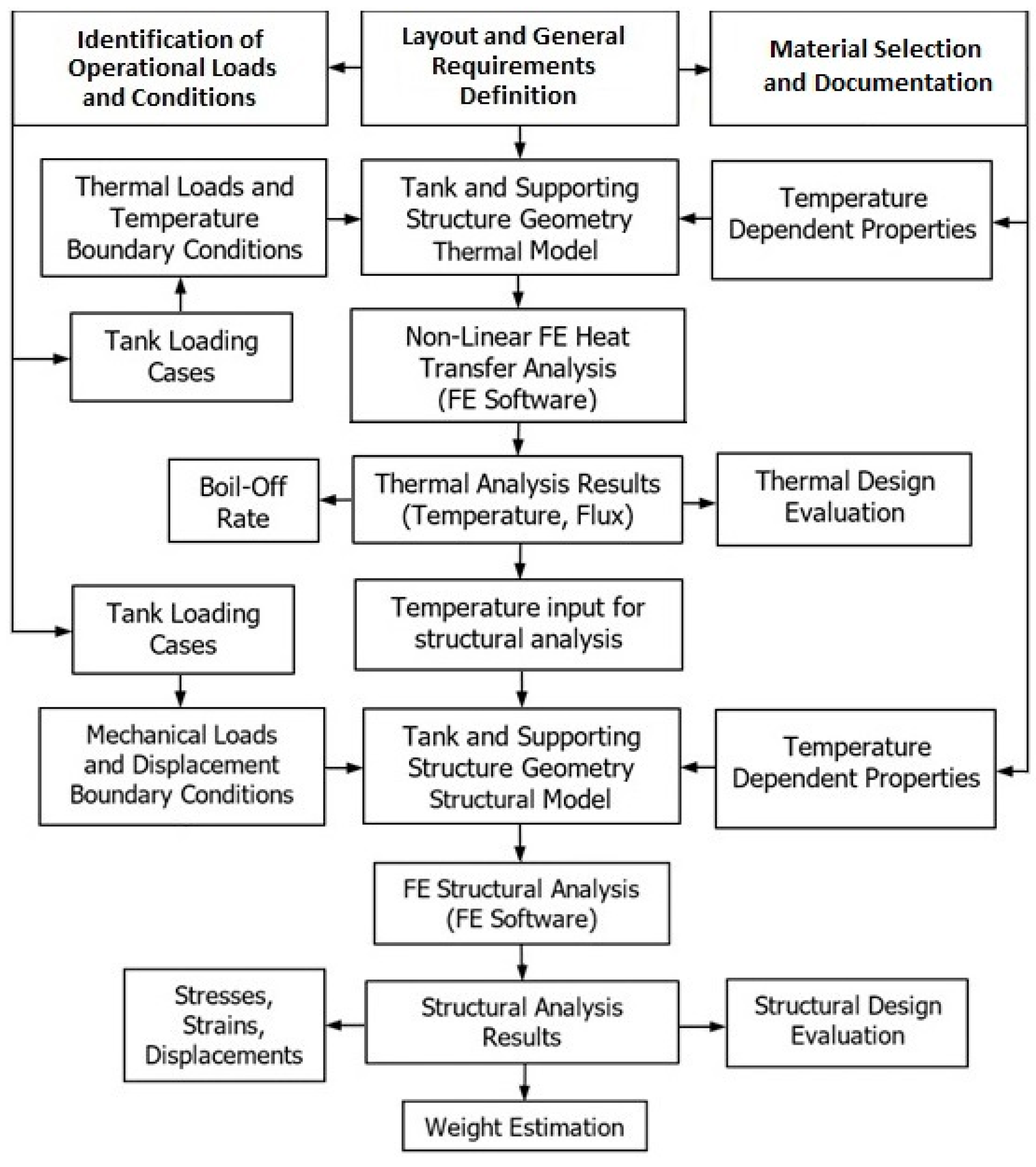
In this direction, the present work refers to the development of a parametric multi-physics finite element model, capable of investigating various design concepts. The developed model comprises a thermal part for the calculation of temperature distributions and heat flux and a structural part that uses the results of the thermal part as inputs and combines them with other mechanical loads in order to perform stress/strain analysis. As a fluid mechanics simulation module is not integrated yet, hydrogen is considered in two separate phases: LH2 and gas. LH2 is modeled as a temperature boundary condition and a hydrostatic pressure load, while gas is modeled as a separate constant pressure load. The simulation results are used to assess both the structural and thermal performance of the tank and its mass efficiency as a function of its design parameters, providing valuable inputs for the optimization process.
The model has a built-in geometry creation module that is capable of creating axisymmetric double-walled tanks, with the length, radius and shape of the domes being modifiable parameters. Cross-section data can also be altered, facilitating design revisions. Material properties are also introduced in a parametric manner, allowing the investigation of different materials. The digital model was developed using code written in the ANSYS parametric design language (APDL), and simulations were conducted in the ANSYS mechanical solver.
The capabilities of the model are demonstrated with the design of a cryogenic tank. The design process commences with the definition of the basic requirements, such as dimensions, capacity, and insulation efficiency. In the present work, a fuel cell-powered commuter aircraft was selected as a case study, with the requirements heavily influenced by the Embraer EMB 120 Brasilia, a typical aircraft of the class. This case study considered the selection of established and well-characterized materials, in an effort to showcase that LH2 aircraft can be developed sooner and with a relatively lower cost by utilizing existing materials and manufacturing methods. Aluminum alloy 2219-T8 was specifically selected for the structural parts of the tank, as this is a well-established material used since the 1960s for the construction of large-scale LH2 tanks of rockets, and its mechanical and thermal properties are well documented over a wide temperature range, including cryogenic temperatures. It has low hydrogen permeability and can also be welded without significant degradation of its properties, making it an extremely attractive material for the tank walls. Polyetheretherketone (PEEK), a high strength thermoplastic, was selected for the inter-tank supports, while light polyurethane (PU) foam was selected for the insulation.
A brief historical background Is provided in
Section 2. Structural concepts, materials, and the state of the art are presented in
Section 3, while an initial design methodology, as well as the general design parameters and requirements are described in
Section 4. The heat transfer and structural analysis processes are described in
Section 5 and
Section 6, respectively. The functions of the model are presented in
Section 7 with the analysis of the investigated tank concept, while conclusions and future work are presented in the final section.
2. Historical Background
The main contributing factor to the discovery of hydrogen as an element in the late 18th century was its flammability. It was immediately identified as a potential fuel and it was first used as such early in the 19th century [
3].
The liquefaction of hydrogen was achieved late in the 19th century [
4], yet due to handling issues related to the cryogenic temperatures, liquid hydrogen was not used as a fuel until 1955, when a United States Air Force (USAF) B-57B Canberra bomber was modified to carry a stainless steel LH2 tank on its wingtip that was feeding one of the two engines. The experiment was successful, with the aircraft flying for about 20 min with one engine running on LH2 [
5].
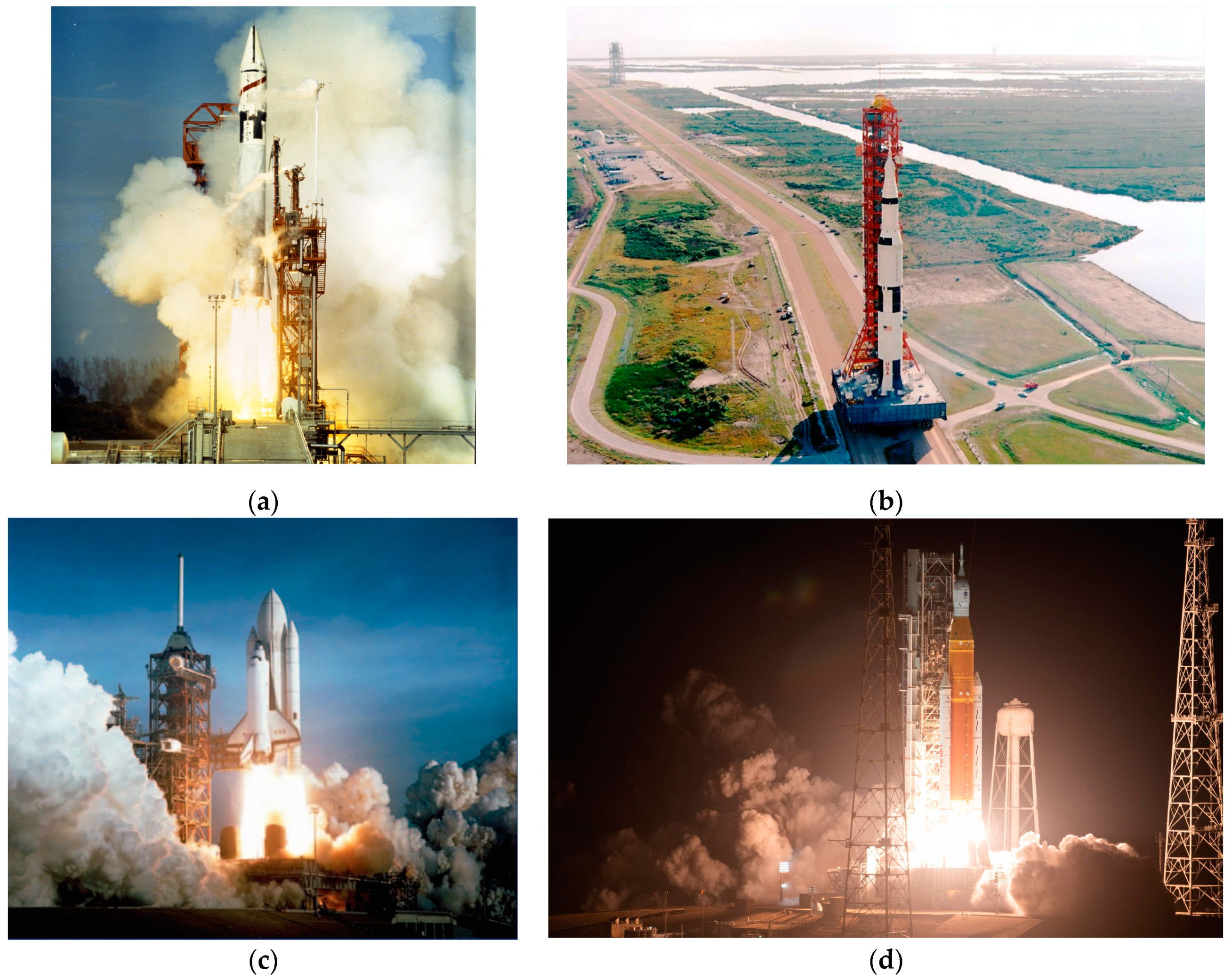
The 1960s saw the first large scale use of LH2 as a rocket fuel. The first successful use of LH2 as a rocket propellant was the Atlas-Centaur, with the Centaur cryogenic upper stage used on top of the Atlas booster, with the first successful flight on 27 November 1963 [
6], shown in
Figure 1a. Cryogenic upper stages were also considered for the Saturn family of rockets of the Apollo program, initially with the S-IV stage of the Saturn I using the same RL-10 engines as the Centaur [
6]. The RL-10 engines of the S-IV were later replaced by the J-2 engines resulting in the S-IVB upper stage, used as the second on the Saturn IB and as the third stage of the Saturn V rocket. The Saturn V, shown in
Figure 1b, had a cryogenic second stage as well, the S-II, and it was powered by five J-2 engines [
7]. The development of the Space Transportation System (STS), better known as the space shuttle, started before the end of the Apollo program, with the maiden flight on 12 April 1981, shown in
Figure 1c. The STS comprises three main components: the space shuttle orbiter where the crew is located, the two reusable solid rocket boosters (SRB) that provide the extra thrust needed for take-off, and the external tank (ET) where the liquid hydrogen and liquid oxygen propellants for the main engines are stored [
8]. The space shuttle program has laid the foundation for the development of the currently used launch vehicle for manned space exploration, the Space Launch System (SLS) of the Artemis program, shown in
Figure 1d. Many space shuttle components were redesigned and repurposed for the SLS including the solid rocket boosters, with a more powerful version using five segments of fuel instead of four, the RS-25 main engines, and the external tank, which was modified to serve as the core stage. The main redesign of the ET was the replacement of the liquid oxygen tank with a cylindrical one, with the liquid hydrogen tank remaining mostly unchanged. The second stage is the same as the Delta IV rocket, again using liquid hydrogen and liquid oxygen as propellants, and it is powered by a single RL-10 engine, the same as the Centaur [
9].
The first major step toward the adoption of LH2 as an aviation fuel was the Tupolev Tu-155 shown in
Figure 2. It is a highly modified version of the Tu-154B airliner, first flown in 1988. A large cryogenic tank was placed in the aft part of the cabin and one of the three engines was running only on LH2. The project was successful with over 100 flights completed before conversion to Liquefied Natural Gas (LNG), as it was easier to handle due to its higher storing temperature of −160 °C, its higher energy density (about 2.3 times more than liquid hydrogen), and mainly due to its significantly lower price and higher availability, especially in the Union of Soviet Socialist Republics (USSR) where the Tu-156, the planned production variant that was to be solely powered by LNG, was supposed to operate [
10].
In 2003, Airbus designed various types of LH2-powered passenger aircraft, ranging from business jets up to long-range airliners. The cryoplane project, as it was called, showed some promising results, with the expected maximum take-off weight (MTOW) of the LH2 aircraft being lower than that of the conventional production airliners [
11].
In 2008, the European Space Agency (ESA)-coordinated Long-Term Advanced Propulsion Concepts and Technologies (LAPCAT) program started the conceptual design of supersonic aircraft capable of flying from Brussels to Sydney in 2–4 h, meaning cruising Mach numbers of 4–8 [
12]. The Mach 8 concept resulted in the 600 ton, LH2-fueled LAPCAT-MR1. An air turborocket propulsion system was selected for the initial acceleration up to Mach 4, and for the final acceleration up to Mach 8 and the cruising stage, a dual-mode ramjet would take over [
13]. The follow-up LAPCAT II program refined the MR1 design and developed the MR2, with significant aerodynamic improvements, as well as the optimization of the propulsion system. The weight was reduced to 400 tons while LH2 remained as the selected fuel [
14].
In 2009, German company H2FLY successfully tested the Antares, the first manned aircraft to be solely hydrogen powered. In 2016, an electric Pipistrel Taurus G4 was modified. Power was provided by a DLR fuel cell with compressed hydrogen stored in tanks within the fuselage. The first flight was successful, with more flights taking place in the following years. Since 2019, the company has been working on a conversion project of a Dornier 328 40-passenger regional propeller-driven aircraft to run on hydrogen fuel cells [
15].
In 2012, Boeing produced the first aircraft to be powered solely by LH2, the Phantom Eye. It was a high altitude and long endurance drone that had two spherical LH2 tanks storing fuel for its two 2.3 L 150 hp (112 kW) internal combustion engines [
16].
Between 2019 and 2022, the EU-funded project ‘Unifier 19’ led by Pipistrel produced a conceptual design of a 19-passenger LH2 commuter aircraft powered by fuel cells. The design showcases various innovative design solutions like distributed electric propulsion, and the ultimate goal was to provide the framework for a zero-emission and silent mini-liner capable of operating from small regional airports with short runways [
17].
In 2020, Airbus launched the ZEROe initiative with the aim of introducing LH2 aircraft by 2035. Modified versions of airliners already in production are to enter service first, with other unconventional concepts like blended wing-body concepts considered for the future [
18].
3. State of the Art
3.1. Insulation Concepts
LH2 is stored at −253 °C while ambient air can reach temperatures exceeding 40 °C during the summer. The difference in temperature causes heat flow from the outside environment to the LH2 stored inside the tank. This heat flow causes hydrogen to boil, increasing the pressure. The excess gas is vented in order to avoid rupture. Therefore, the heat flow toward the liquid is directly translated to a loss rate called the boil-off rate (BoR). Therefore, in order to minimize losses to an acceptable rate, the tank should be adequately insulated. The three main insulation concepts are vacuum-insulated (known as Dewar type tanks), material-insulated, and non-insulated tanks [
19].
Dewar tanks have a double-wall design with a vacuum in between. They are the most thermally efficient type of tank, as heat can be transferred by radiation, while conduction is possible only through the supporting structure between the internal and the external walls that usually has the smallest possible cross section. As the main heat transfer mechanism is radiation, the walls have highly polished surfaces in order to reduce emissivity. Layers of reflective membranes (multi-layer insulation/MLI) between the two walls can further reduce the heat flux and thus the boil-off rate. Since there is a vacuum between the two walls, the structures of both walls must be reinforced, as the outer shell must withstand the atmospheric pressure loads, and the inner tank has to withstand a pressure differential increased by 1 atm. Maintaining the vacuum can also be difficult, especially for larger tanks, necessitating the use of vacuum pumps. Therefore, the main disadvantages of the Dewar concept are increased overall weight, complexity, and cost.
Material-insulated tanks are a much simpler concept as the tank is covered by layers of insulating materials with low thermal conductivity. As most insulating materials have poor mechanical properties and their properties rapidly degrade after exposure to humidity, solar radiation, etc., they are usually protected by an outer shell. The outer shell is often only used to protect the insulation, while in many cases, it can be a load bearing structure. Material-insulated tanks are usually inexpensive and lightweight, with their main disadvantage being their poor thermal insulation efficiency when compared to Dewar tanks, as the main heat transfer mechanism is conduction.
In cases like the propellant tanks of rockets, weight reduction is of utmost importance, while the filled tank is exposed to ambient conditions for only a few hours as rockets are filled on the launch pad shortly before take-off. If the operational time is short and weight reduction is critical, the tanks may not be insulated.
3.2. Structural Concepts
LH2 tanks usually have a large volume, and they are mainly cylindrical with spherical or elliptical domes in order to reduce pressure-induced stresses. The structural concept of a cryogenic tank greatly depends on the application. Stationary tanks are usually subjected to storage overpressure, the weight of the LH2, and hydrostatic pressure. For vehicle tanks, the previously mentioned loads are combined with inertia loads, as well as other structural loads depending on design and integration. The main structural concepts are the independent, the integrated, and the integral tanks [
19].
When a tank is placed in a specifically designed compartment of the vehicle and is mounted in a manner such that it only receives internal and inertial loads, it is identified as an independent tank. Such tanks do not interfere with the structure of the vehicle and only cause inertial loading. They are thermally isolated from the rest of the vehicle and do not cause any thermal gradients on the structural parts. Independent tanks may be handled like cargo, and they can usually be easily removed, facilitating maintenance. The main disadvantage of this concept is the increased weight.
As the majority of insulated tanks require an outer shell, either to maintain the vacuum or to protect the insulation, some designs use a structural part of the vehicle as the outer shell. This is the integrated tank concept, which has the advantage of weight reduction and increased volume efficiency. This concept, though, may have issues, as the inner cryogenic tank, which has a temperature of around −250 °C, is directly connected to the load bearing structure via the inner tank supporting structure. This means that the load bearing structure may be subjected to low temperatures and temperature gradients, with possible thermal fatigue effects due to expansion and contraction under different thermal loading conditions. An integrated tank has to be specifically designed for the vehicle it will be placed in.
For applications where weight reduction is critical and no outer shell is used, the cryogenic tank itself may become a structural part of the vehicle. This is a common design solution for rockets, where the tank structure is the core of the vehicle with other components mounted on it. Such tanks may also be insulated like the space shuttle external tank or the core stage of the SLS rocket of the Artemis program, where foam insulation is used.
3.3. Materials
For the construction of a cryogenic tank, several materials are considered for the structural parts and the insulation. For the inner tank, the most common materials used are metals. For lightweight applications, the main material is aluminum–copper alloy 2219, which has been used since the 1960s. During the late 1980s, aluminum–copper–lithium alloy 2195 was developed. It has a higher tensile strength and a lower density than 2219 and can also be welded. Aluminum 2219 was the main material for the construction of the space shuttle external tank until 1998 when it was replaced by aluminum 2195. The new material selection significantly decreased the overall weight of the external tank, with the 2219 tank having an empty weight of 66,000 lbs (30,000 kg) and the new 2195 tank having an empty weight of 58,500 lbs (26,500 kg) [
20]. Although 2195 has better properties and a significant weight reduction potential, it was not selected for the core stage of the SLS rocket due to its high cost, with friction stir welded (FSW) aluminum 2219 being selected instead. Type 304, 310, and 316 austenitic stainless steel alloys are another preferred material for cryogenic tanks due to their high strength, weldability, resistance to hydrogen embrittlement, and low cost. Fiber-reinforced polymers are also investigated as candidate materials for the inner cryogenic shells, but the difference in the thermal expansion coefficients of the matrix and fiber materials cause significant stresses, especially under cryogenic conditions [
19]. Carbon fibers have a negative coefficient of thermal expansion (CTE), while most polymers have a relatively high and positive CTE. As the fibers expand, the polymer that contracts experiences severe tensile stresses that can generate cracks, which result in leaks and even structural failure. Polymers also have significantly higher hydrogen permeability when compared to metals. The long-term behavior of composites under LH2 conditions is currently under investigation, although progress is slow due to the high complexity and cost of LH2 tests.
The outer shell is generally not subjected to cryogenic temperatures and generally does not come in contact with hydrogen as much as the inner shell. If the outer shell is load bearing, materials with high strength and specific properties are preferred. Metals like aluminum and steel alloys are a common option. Since there is no exposure to cryogenic temperatures, composites may also be selected, as the temperature difference is not high enough for the different CTEs to cause an issue. Carbon fiber composites offer high specific properties, but with a cost penalty. Glass fiber composites can be a less expensive alternative at the cost of lower mechanical properties. Matrix materials can be thermoplastic or thermoset polymers.
The inner tank-supporting structure materials should have a combination of high strength and low thermal conductivity. Various materials may be considered. Metals are a common option, offering high strength. Their high thermal conductivity may be countered by selecting supports with small cross-section area and large equivalent length, increasing their thermal resistance. High-strength polymers are also common. PEEK is a thermoplastic polymer with high strength, but it has a high cost. High-density polyethylene (HDPE) is a less expensive alternative but with a lower strength. Thermoset polymers like bakelite are also viable. Ceramics may also be used due to their high strength, but their high weight renders them less suitable for vehicle applications. As the inner tank-supporting structure experiences high temperature gradients, with cryogenic temperatures on the one side and near ambient conditions on the other, composites are not usually preferred due to the CTE mismatch. A summary of the structural materials and their advantages and disadvantages is presented in
Table 1.
Several insulation materials like polymers, ceramics, and aerogels may be used. Polymer foams are inexpensive, easily applicable and have extremely low densities. Most foams, though, have poor mechanical properties that degrade after exposure to humidity and solar radiation and, therefore, a protective outer shell should be placed in order to protect them for outdoor and long-term applications. Ceramics are heavy and have higher conductivity, but they have superior mechanical properties. In some cases, ceramic insulation is capable of bearing loads, eliminating the need for an inner tank-supporting structure. Perlite powder is also a common insulator for cryogenic applications, although it has high weight and as a powder it can settle down under dynamic loads, rendering it suitable only for stationary applications. Aerogels are highly porous materials with extremely low thermal conductivity. Their mechanical properties are extremely poor, meaning they should be protected by an outer shell. Aerogels are generally expensive, and their properties are not well documented yet, but they show significant potential for future applications. A summary of the insulation materials and their advantages and disadvantages is presented in
Table 2.
3.4. Computational Tools
Finite element methods are usually employed for the analysis of complex structures. Several digital solvers exist offering structural, thermal, and fluid mechanics simulation capabilities. During the late 2010s, finite element analyses of LH2 tanks for aircraft applications became more extensive as LH2 aircraft designs started progressing beyond the conceptual stage. Following the LAPCAT II program, the design and structural analysis of composite LH2 tanks was conducted under the EU-funded Cryogenic Hypersonic Advanced Tank Technologies (CHATT) project. Finite element simulations of the tank provided valuable information regarding the structural and damage tolerance behavior of the four-sphere composite tank [
21]. The simulation results were later validated under pressure and thermal loading conditions [
22].
In the same time period, there were also LH2 tank integration studies, with the development of finite element simulations of tanks within fuselage sections. A study conducted by Gomez and Smith [
23] introduced two aluminum LH2 tanks in the fuselage of the MRT7-3 ‘Meridian’ concept aircraft, one forward and one aft. The developed finite element models of the tanks and fuselage sections contained structural details such as stringers and frames and were capable of estimating boil-off rates and stresses and displacements of the structures under different loading conditions such as pressure, thermal, and flights loads.
The early 2020s saw the development of computational tools capable of investigating and comparing different design concepts and geometries, as interest around independent-type tanks increased to their ability to be introduced into different aircraft. Mantzaroudis and Theotokoglou [
24] developed a model capable of conducting the structural and thermal analysis of independent-type foam-insulated double-walled LH2 tanks and drawing conclusions regarding several key performance indicators such as gravimetric index and boil-off rate. The simulations consider temperature-dependent material properties and thermal and pressure loading conditions, although without the inclusion of structural details such as stringers and supports.
The present work describes the development of a computational tool that combines the parametric design approach with the inclusion of structural details such as frames and supporting structures, while also including a preliminary fluid mechanics module that can simulate the behavior of LH2 under acceleration loads. The simulated loading cases are expanded by including aircraft-induced acceleration loads, a critical load case for certification under the Federal Aviation Administration (FAA) 14 CFR or the EASA CS regulations.
5. Heat Transfer Analysis Methodology
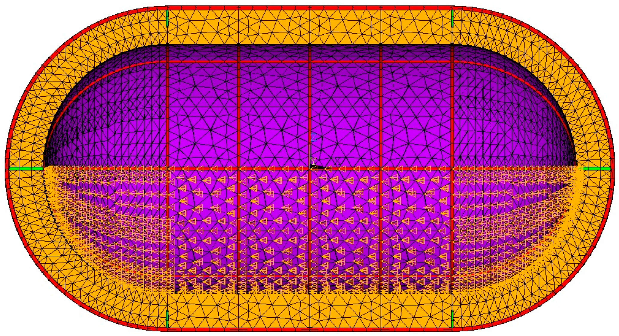
The non-linear heat transfer finite element analysis is the first module of the numerical model. The tank geometry is created by a parametric code, with design parameters such as diameter, length, insulation thickness, etc. being variables. The model supports any axisymmetric shape for the tank, yet in this case, a traditional pressure vessel geometry of a cylinder with two spherical domes will be modeled. The tank geometry is subsequently meshed with elements with temperature degrees of freedom. The tank walls are meshed using the triangular options of four-node thermal thin shell elements. Inner and outer wall areas are grouped separately, allowing meshing with different section types. The supporting structure beams are meshed with two-node thermal link elements. The beams are meshed by selecting specific lines of the geometry in a parametric manner. The inner tank-supporting structure tubes and rings made of PEEK are also meshed with thermal link elements. The cross-section area is a required input for these elements, and it has to be the same as the cross-section area of the beams used. The thermal mesh is presented in
Figure 4.
The insulation is meshed with tetrahedral options of 20-node coupled field higher-order solid elements, with displacement and temperature degrees of freedom activated, that are part of both structural and thermal analysis modules, as seen in
Figure 5. Using the same elements for both modules allows the analysis to be conducted in systems with smaller memory capacity, at the expense of longer required time for the analysis process to conclude. A selection was made for 20-node solid elements instead of 8-node ones in order to increase the number of nodes for a more accurate through-the-thickness temperature distribution within the insulation, without increasing the number of elements.
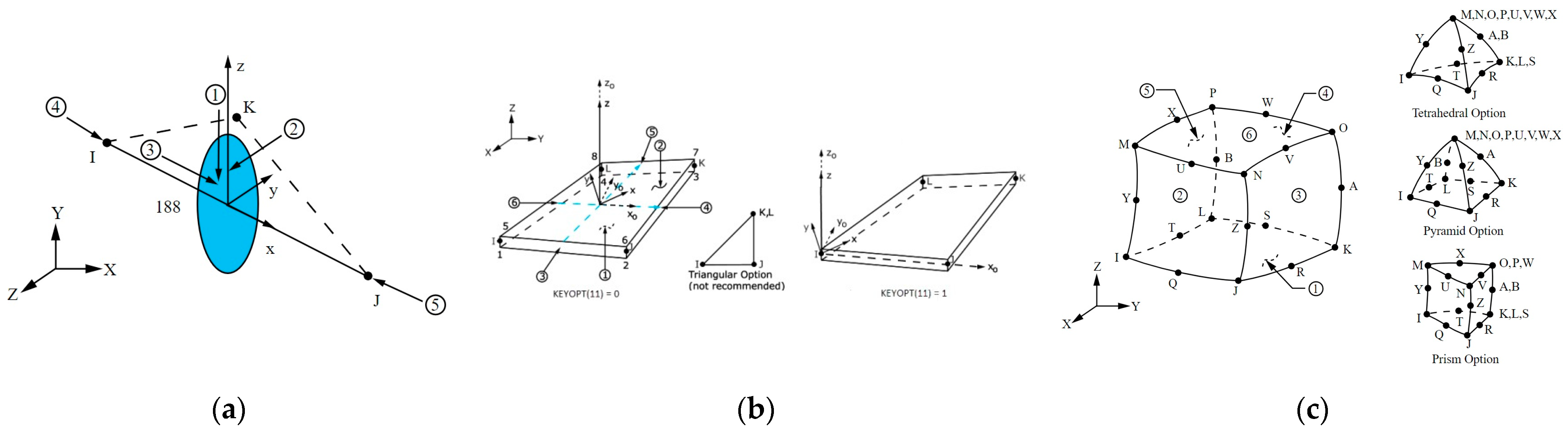
All the elements used by the heat transfer analysis module are presented in
Figure 6.
The surface of the inner tank shell that is in contact with the LH2 is assumed to have the same temperature as the liquid. Therefore, all nodes belonging to elements of the inner tank shell below the surface of the liquid are selected and assigned the boiling temperature of hydrogen for each internal pressure load case as a boundary condition, as shown in
Figure 7. The worst thermal load case is LH2 at atmospheric pressure, with a boiling temperature of 20 K.
The outer shell surface is in contact with air inside the aircraft. The main heat transfer mechanism is natural convection, as a flow is induced by buoyancy forces due to temperature differences within the volume of the fluid. The flow in a free convection boundary layer depends on the relative magnitude of buoyancy and viscous forces and it is characterized by the dimensionless Grashof number (Gr), calculated as per Equation (3):
where:
g is gravitational acceleration
β is the CTE of the bulk fluid
is the temperature of the surface
is the temperature of the bulk fluid
is the kinematic viscosity of the bulk fluid
is the characteristic length of the surface
The dimensionless Rayleigh number (Ra) gives the ratio of buoyancy forces and thermal and momentum diffusivities. It is the product of the Grashof number and the Prandtl number (Pr), calculated as per Equation (4):
Convection phenomena are correlated by the dimensionless Nusselt number. The convection coefficient is a function of the Nusselt number (Nu), calculated as per Equation (5):
where k is the thermal conductivity of the bulk fluid.
The Nusselt number can be calculated as a function of the Rayleigh and Prandtl numbers via simple empirical correlations for a variety of known geometries [
33]. The outer tank surface can be divided into two sections: the central cylinder and the two spherical domes. Nusselt number correlations are available for both geometries. For the horizontal cylinder, the Nusselt number is calculated as per Equation (6):
The Nusselt number for the sphere is calculated as per Equation (7):
For both geometries the characteristic length is the diameter. The convection coefficient is temperature dependent; therefore, it should be calculated for a certain number of surface temperatures. Air properties at the average temperature should be used when calculating the dimensionless numbers and the convection coefficients for more accurate results. Convection loads are applied on the elements of the outer tank cylinder and domes as seen in
Figure 8, using the bulk fluid (ambient air) temperature of 300 K and the parametrically calculated temperature-dependent convection coefficients as inputs.
With loads and boundary conditions defined, the non-linear heat transfer analysis is conducted. It may take several iterations for the analysis to converge, as the temperature-dependent properties are redefined for each iteration according to the previously calculated temperature. The convergence tolerance criterion is set at 0.5%, meaning the analysis is concluded when an iteration produces results with a maximum divergence in temperature and heat flux values of 0.5% or less when compared to the previous iteration. A mesh convergence study should also be conducted, examining different finite element sizes, with each iteration decreasing the element size, with the mesh assumed converged only when producing results within a 2% margin of the previous mesh. The results of the heat transfer analysis are stored in a separate results file for further use in the structural model. The heat flow toward the LH2 can be calculated by the model as a reaction, and subsequently, the BoR can be calculated. The obtained temperature distributions and heat flow results can be used in order to assess the thermal design of the tank and the efficiency of the insulation.
6. Structural Analysis Methodology
The geometry created for the heat transfer analysis is meshed with elements having structural degrees of freedom. The inner and outer tank shell are meshed using triangular options of 4-node structural thin shell elements with bending and membrane stiffness. As is the case with the thermal elements, inner and outer shell elements are grouped separately, allowing meshing with different section types of different thickness. For each specific structural shell element, the section type and section properties are the exact same as those used for the thermal mesh. The beams are meshed by selecting specific lines, as was the case in the thermal mesh. The 2-node beam elements are used, with structural degrees of freedom. The beam elements require the geometry and specific dimensions of the considered cross-section, as well as its orientation, in order to calculate bending stresses. The coupled field solid elements generated for the heat transfer analysis are retained and used for the structural analysis. The structural mesh is presented in
Figure 9.
All the elements used by the structural analysis module are presented in
Figure 10.
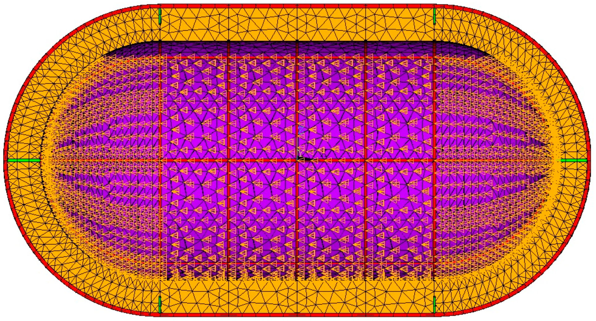
Mounting points on the outer shell surface are selected and given 0 structural degrees of freedom. The mounting points are parametrically selected, and the preferred locations are the intersections between stiffening beams, shown in
Figure 11, as the beams are more capable of bearing concentrated loads.
Acceleration values along all three axes are the first structural load inputs. Triaxial acceleration is subsequently applied to all structural elements. The density of each material is used as an input for all structural elements; therefore, their mass and inertia load under acceleration can be calculated.
Pressure is the major structural load for independent tanks, and it consists of two parts: storage overpressure and hydrostatic pressure. Storage overpressure is a design parameter and model input. However, hydrostatic pressure has to be separately calculated and applied to each element. An array with the numbers of the inner tank shell elements is first created. Each element is individually examined using a loop code. The coordinates of the element centroid are used to calculate the distance between the element and the surface of the LH2, for each specific filling case and acceleration scenario, as the surface is shifting, always remaining vertical to the total acceleration vector. The hydrostatic pressure is calculated as per Equation (8):
where:
g is the total acceleration
ρ is the density of the fluid
is the distance between the element centroid and the surface of the fluid
The hydrostatic pressure is then added to the storage overpressure and, subsequently, the combined pressure is applied to the element. If an element is above the surface, only the storage overpressure is applied. An example of a hydrostatic pressure load case is presented in
Figure 12. The hydrostatic pressure is also used to model the inertial load of the LH2, which is combined with the inertial loads of the rest of the structure. The model is limited to static loads; therefore, no dynamic sloshing loads are considered, as this would require a separate computational fluid mechanics module.
The temperature distribution is loaded from the results file of the heat transfer analysis and is used as an input for the structural analysis. The structural and thermal meshes are identical; therefore, temperature values are available for all nodes, without any processing of the temperature distribution required. A reference temperature is defined for thermal strain calculations, and the temperature distribution is used in order to define the temperature-dependent mechanical properties.
The linear structural analysis is subsequently conducted, as the mechanical properties are not dependent on the structural degrees of freedom, since small displacements are expected and the materials are assumed to have linear elastic behavior. As was the case with the heat transfer analysis, a mesh convergence study is conducted. The resulting stresses, strains, and displacements are used in order to assess the structural design, and potential design revisions can be facilitated.
7. Analysis of the Investigated Tank Concept
The design process starts with the thermal design of the tank, which will result in the definition of the required insulation thickness for the target BoR of 18% per day. The outer tank diameter is set at the maximum value of 2.2 m, as this will result in the minimum overall length. The inner tank capacity should also remain constant at 7 m
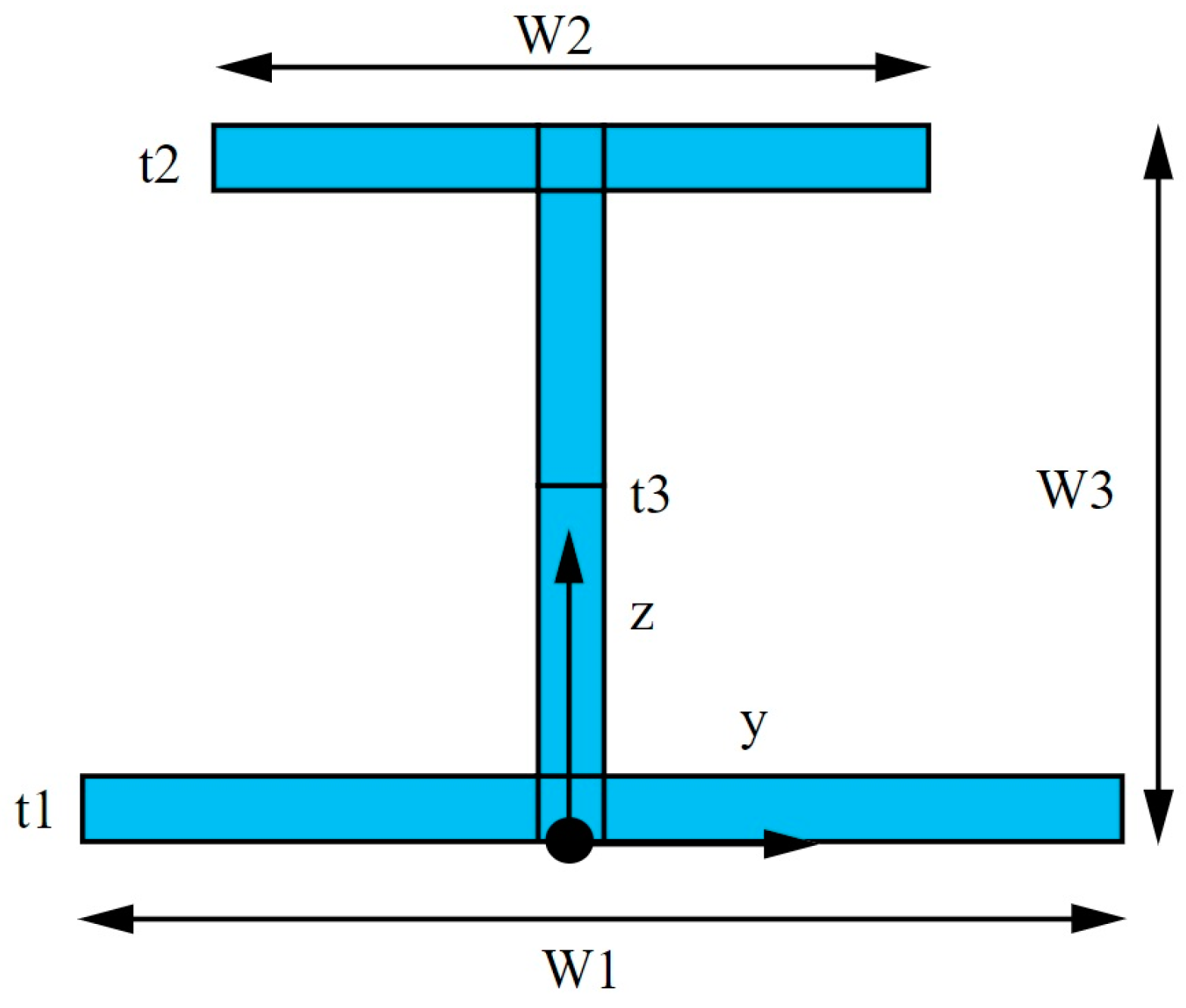
3, as this corresponds to the required amount of fuel. The inner tank-supporting structure is sized in a conservative manner by selecting a hollow circular cross-section with an outer diameter of 5 cm and a thickness of 2.5 mm made out of PEEK. The tank is supported axially by two continuous PEEK tubes and radially by a staggered arrangement of PEEK tubes on a PEEK ring with an I cross-section, with the geometry explained in
Figure 13. The overall depth of the rings is 20 mm, the width of the flanges is the same as the tube diameter at 50 mm, and all elements have a thickness of 2.5 mm.
The sizing of the aluminum components is not taken into consideration during this early design stage as even moderate changes in thickness will have a negligible impact on thermal performance due to the significantly higher thermal conductivity of aluminum when compared to PEEK or PU32.
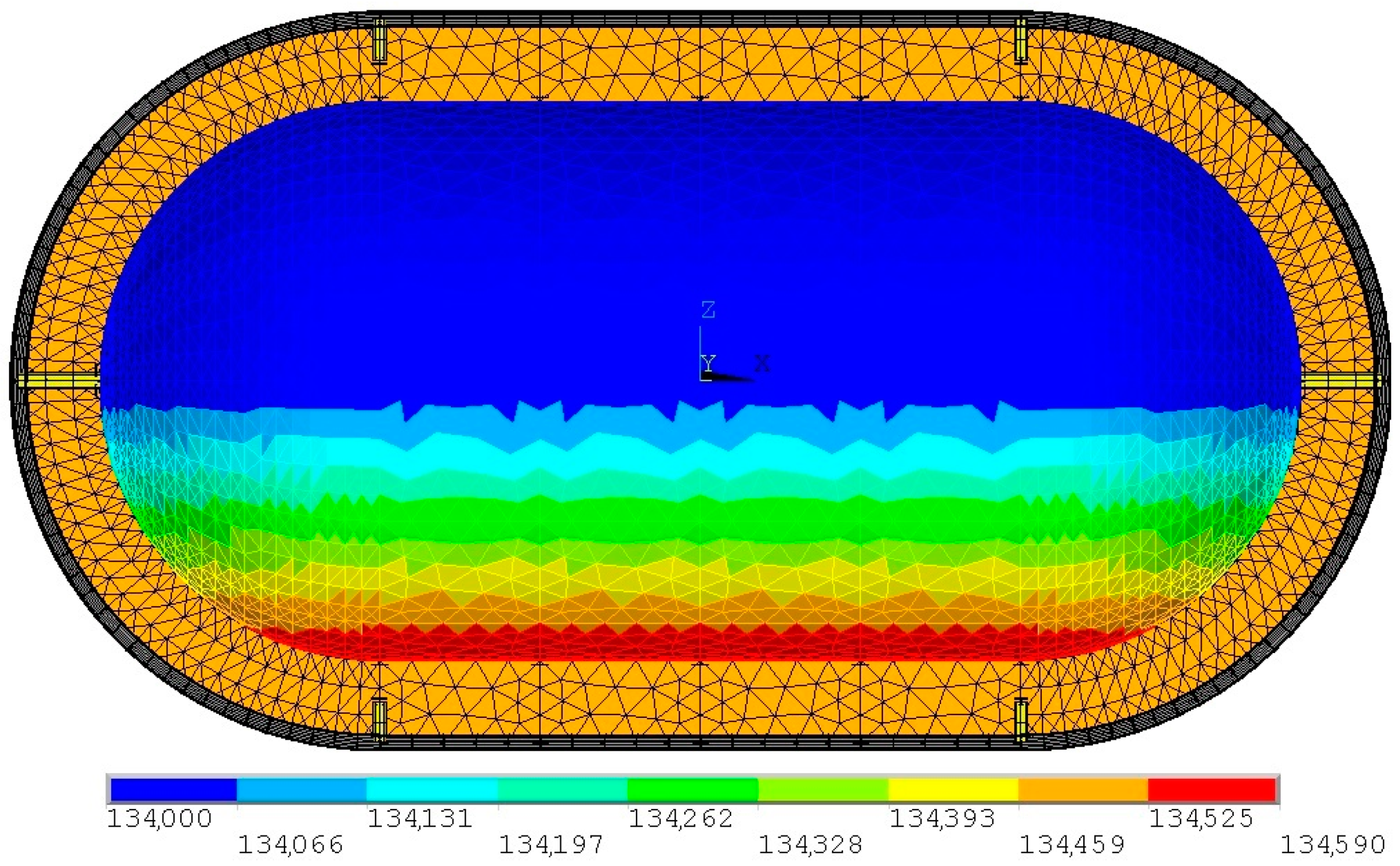
Thermal analysis is performed for a fully filled tank at 95% of its volume capacity, as shown in
Figure 14, for different insulation thicknesses. With the outer tank diameter and internal volume constant, the overall length is a function of the insulation thickness. Tanks with different insulation thicknesses are presented in
Figure 15.
Heat flow, total length, total outer surface area, total volume, and insulation mass results are compared for the different investigated thicknesses in
Table 11. The boil-off rate is a direct function of the heat flow and is calculated as per Equation (9):
where:
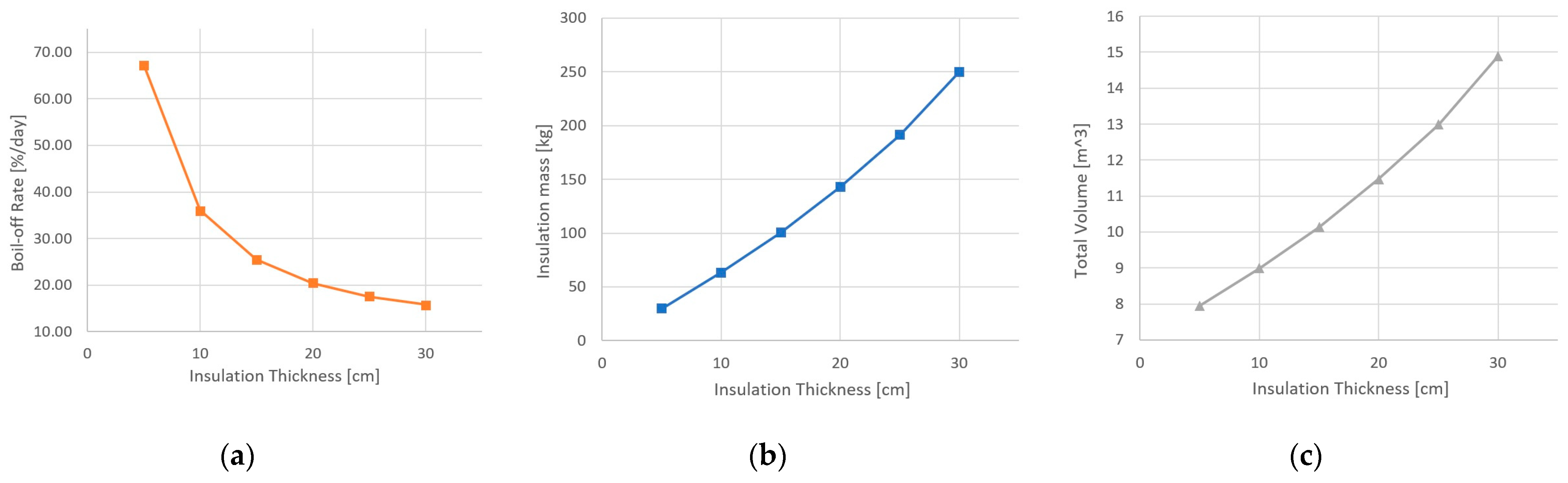
While increasing the insulation thickness is supposed to reduce the heat flow, it also increases the outer surface area, as the tank should be lengthened in order to retain the required volume, while compensating for the reduction in diameter. The increased outer surface area consequently increases the heat flow. Therefore, excessively increasing the insulation thickness for a fixed outer diameter and capacity does not significantly improve the thermal performance while only increasing the overall length and weight. Plots of the boil-off rate and insulation mass results from the insulation thickness trade-off study are presented in
Figure 16.
The boil-off rate requirement is met by a 25 cm or thicker layer of PU32 insulation. As a further increase in insulation thickness will significantly increase the overall length and weight of the tank without any considerable boil-off rate reduction, the trade-off study is concluded, and a 25 cm-thick insulation layer is selected.
With the insulation thickness selection finalized, inner and outer tank dimensions can be defined next. A summary of the dimensions is provided in
Table 12:
Both tanks are cylindrical with spherical domes. The domes are concentric, and as a result, both tanks have a 1.95 m long cylindrical section.
The next stage of the design process is the sizing of the inner tank and its stiffening structure. A stiffening structure comprising rings and longitudinal beams is considered in order to reduce stress concentrations resulting from the inertial loads and the shape of the supporting PEEK tubes.
Rings and beams will share the same I cross-section. An overall depth of 30 mm, width of 50 mm defined by the diameter of the supporting PEEK tubes, and a thickness of 3 mm for elements are selected. Overall, five evenly spaced rings will reinforce the cylinder that experiences higher stresses, and six evenly placed longitudinal beams will reinforce the whole inner tank structure.
The thickness of the inner tank wall sections is initially defined by an analytical calculation for thin-walled pressure vessels considering pressure as the only load and not accounting for any stiffening structure. Equations (10) and (11) define the required thickness for a cylindrical and a spherical pressure vessel, respectively.
where:
The tank should be sized for a MEOP of 2.08 bar differential pressure. According to ANSI/AIAA S-080A-2018 [
30], for a proof pressure of 3.12 bar, stresses should not exceed the yield strength of the Al 2219 welds divided by the stress safety factor (143 MPa). Furthermore, for a burst pressure of 4.16 bar, stresses should not exceed the ultimate strength of the Al 2219 welds divided by the stress safety factor (252 MPa). Although the material strength increases at cryogenic temperatures, the room temperature strength values are considered. The theoretical required thicknesses of the cylinder and the domes for each pressure scenario are summarized in
Table 13.
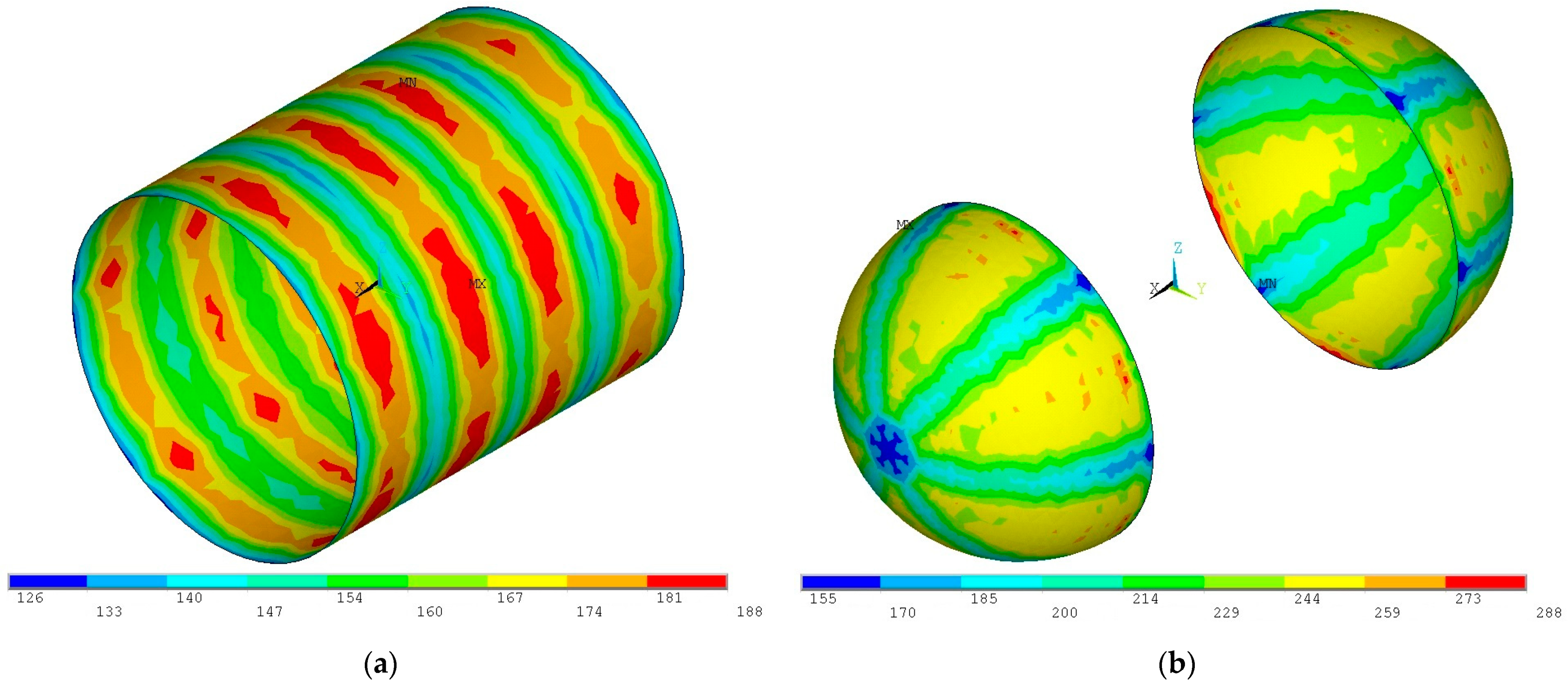
A thermomechanical analysis is conducted initially considering a cylindrical section of 12-gauge (2.05 mm) aluminum 2219 sheet and two spherical sections of 18-gauge (1.02 mm) aluminum 2219 sheet with the tank subjected to the combined thermal, proof pressure, and inertial loads. The resulting von Mises stress distributions are presented in
Figure 17.
As seen in
Figure 14, the von Mises stresses on all sections of the inner tank exceed the maximum allowed of 143 MPa, as the inner tank wall was sized only for pressure, without considering the other loads. An iterative process is conducted where gradually thicker sheets are examined until the von Mises stresses are reduced to the acceptable value, below 143 MPa.
After several iterations, it has been concluded that the thinnest available aluminum sheets capable of safely bearing the loads are 8 gauge (3.26 mm) for the cylindrical part and 9 gauge (2.91 mm) for the domes, with the von Mises stress distributions presented in
Figure 18.
For the same load case, the inner tank-stiffening structure experiences a maximum stress value of 130 MPa, with the von Mises stress distribution presented in
Figure 19.
With the inner tank sized for a proof pressure differential of 3.12 bar under maximum combined loads, structural analysis is conducted for the burst pressure load of 4.16 bar. As seen in
Figure 20, von Mises stresses on the inner tank wall and its stiffening structure do not exceed the maximum allowable stress for burst of 252 MPa; therefore, the inner tank conforms to the ANSI/AIAA S-080A-2018 standard [
30].
With the inner tank sizing process finished, the outer tank sizing process begins. The outer tank is sized with the same stress safety factor of 1.4 as the inner tank, leading to a maximum allowed stress of 143 MPa as no plastic deformation should be present, with the combined proof pressure, acceleration, and thermal loads applied. The outer tank is stiffened by three evenly spaced rings with an I cross-section. An overall depth of 50 mm, a width of 75 mm, and a thickness of 5 mm for elements are selected. The outer tank-supporting structure also includes six evenly placed longitudinal beams with an I cross-section with an overall depth of 50 mm, a width of 50 mm, and a thickness of 5 mm for elements. After an iterative process, a 14-gauge (1.63 mm) aluminum 2219 sheet is selected for the outer tank shell. Von Mises stress distributions for the combined loads are presented in
Figure 21.
The inner tank supporting structure will be sized next. An initial analysis is performed with the supporting structure that was defined during the insulation sizing. The stress safety factor is again 1.4, resulting in a maximum allowable stress of 69 MPa. The resulting stresses are presented in
Figure 22.
Stresses on the axial supporting tubes are within the limit, yet the radial supports experience low stresses. Therefore, the radial supports are reduced in size, with the I cross-section ring width of the flanges reduced to 40 mm and the thickness of the elements reduced to 2 mm, while retaining the 20 mm depth. The diameter of the axial tubes is reduced to 40 mm, while their thickness is reduced to 1 mm. Since the von Mises stresses on the axial supports is close to the limit value, the axial supporting tube thickness is increased to 3 mm in order to compensate for the overall reduction in stiffness of the radial supports. Von Mises stress distributions on the new supporting structure are presented in
Figure 23.
With all the structural elements sized, a final simulation is conducted with the combined proof pressure loads in order to examine the insulation and identify any potential failures in the PU32 foam that could lead to excess boil-off. As seen in
Figure 24, insulation stresses are lower than the tensile strength; therefore, there is no risk of insulation damage. As insulation is not a structural element, a minor flaw will most likely not lead to a catastrophic failure, as the increased boil-off gas can be safely vented through a safety valve.
The final design iteration leads to a heat flow of 419.1 W, which translates to a BoR of 17.48% per day, slightly reduced due to the reduction in the size of the radial supporting structure cross-section. The mesh for both thermal and structural analyses converged for an element size of 10 cm. With von Mises stresses on all structural elements for the combined loads within the limits of the regulations and with the insulation system achieving an acceptable BoR, the design process of the tank can be concluded, and the finalized tank design is presented in
Figure 25.
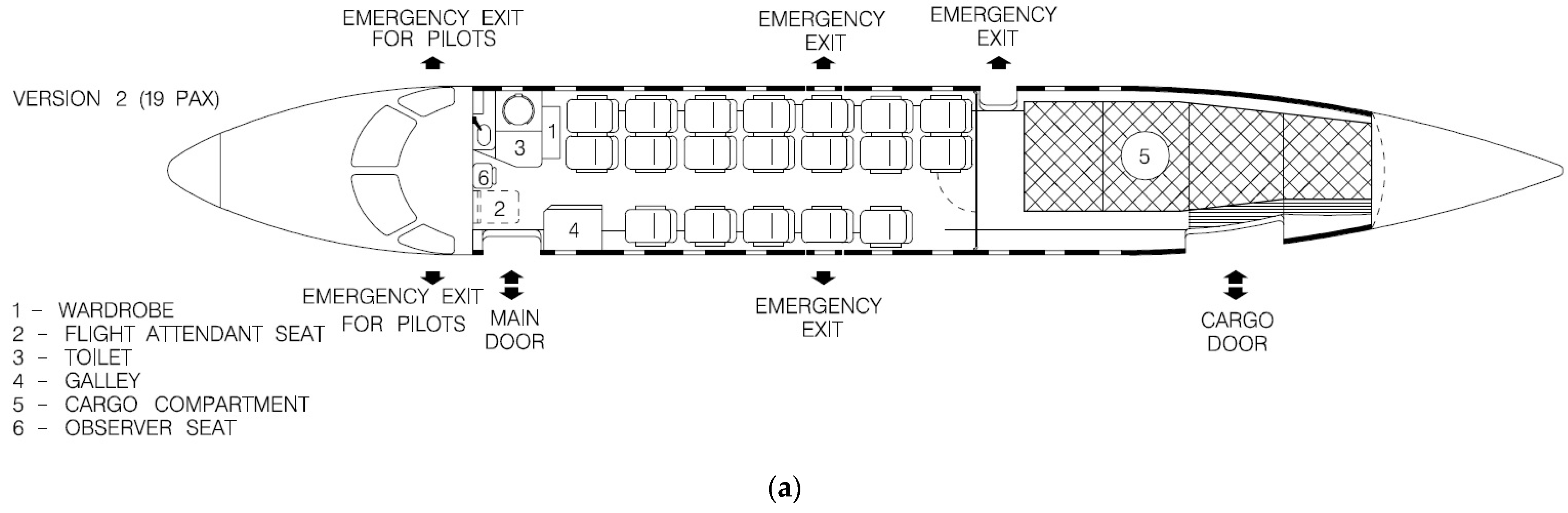
The investigated tank concept has been designed for easy integration to commuter aircraft, with the EMB-120 used as a guideline. A conceptual EMB-120 retrofitting study has been performed, placing the LH2 tank in the cargo bay of the 19-seat combined cargo-passenger version, seen in
Figure 26a. The majority of the cargo bay space is occupied by the tank, although it still leaves space in the aft for baggage. As there is no need for access to the cargo bay from the cabin, the rear cabin door has been deleted, and in its place, two additional seats have been fitted, increasing the capacity to 21 passengers. The cargo bay windows and emergency exit have also been deleted, as they are no longer needed with the tank occupying this space, contributing to a potential decrease in weight. The tank has been placed as close to the main wings as possible in order to decrease the effect of the constantly reducing fuel mass on the trim of the aircraft, although this effect is less severe with LH2 due to its low density. The 21-passenger concept is presented in
Figure 26b.
8. Conclusions and Future Work
An FSW aluminum 2219 LH2 tank has been designed with the assistance of a parametric and multi-physics finite element simulation. The finalized tank has a capacity of 465 kg of LH2, enough for a hydrogen fuel cell-powered commuter passenger aircraft equivalent to the Embraer EMB-120 Brasilia. The overall mass of the tank is 674 kg, excluding piping and peripheral equipment. The cross-sections and masses of each component are described in
Table A1. An indicator of the mass efficiency of a tank is the gravimetric index, calculated by dividing the mass of the stored fluid by the combined mass of the fluid and the tank. With the combined LH2 and tank mass at 1139 kg, the gravimetric index is 0.41. The combined mass of LH2 and the tank is less than half of the replaced 2600 kg of fossil fuel. Even when considering the additional mass of piping and valves, there is a significant MTOW reduction for a hydrogen fuel cell aircraft when compared to a conventional one. The weight reduction is estimated around 1 ton, accounting for about 8% of the 12-ton MTOW of the EMB-120. The designed tank indicates that LH2 is a viable aviation fuel for the future and that aluminum 2219 is a serious candidate material for the construction of aviation cryogenic tanks.
The design process was significantly aided by the developed parametric finite element model as design aspects could be easily altered and evaluated. The sizing of each component could be effectively conducted, and an optimal solution could be found after a number of iterations, while also understanding the effect that each component has on the overall performance of the tank, as it was evident that increasing the insulation thickness for a tank with set capacity and outer diameter beyond a certain extent has a minimal effect on the BoR. The simulation also allowed a better understanding of the effects of certain loads, as was the case with the inner tank, where the thickness had to be significantly increased despite being reinforced with longitudinal beams and rings due to the severity of the thermal contraction loads. Beyond component sizing, the model can also predict the behavior of the tank under different operational loading conditions and produce results that could be used for other studies, like the integration into the aircraft and fatigue life predictions.
The current version of the model is capable of applying static and quasi-static loads. Future versions will also include transient loading cases such as filling. The temperature boundary conditions on the inner tank will also be replaced with loads derived from the boiling curve of hydrogen in order to better simulate heat convection and provide more accurate results, especially for the transient loads. The structural module will also be improved with the addition of interface elements capable of simulating connections and welds, in order to improve the accuracy of the results. The geometry of the model will also be updated in order to include several peripheral equipment units that could affect the performance, like piping and endcaps. The next versions of the model will also include a third fluid mechanics module, in order to simulate dynamic phenomena like sloshing, caused by the movement of LH2 inside the tank during maneuvers. The aim of these additions and improvements is to create a digital twin of the tank, being as close to an actual built tank as possible.
Experimental data under combined mechanical and cryogenic conditions of LH2 tanks are rare or even non-existent. In order to assure that the predicted behavior by the tank FE model agrees with the behavior of the actual tank under the specified loading conditions, the results of the model have to be compared to results from experimental campaigns. The validation of the modeling techniques under realistic loading conditions is planned to be conducted in the near future by exploring the experimental data that will be derived in the EU-funded project fLHYing tank [
44]. In the frame of fLHYing tank, an independent-type liquid hydrogen tank will be manufactured and flight tested in a hybrid-electric VTOL unmanned cargo aircraft. The thermo–fluid–structural digital twin of the system which is currently under development using the modeling techniques described in the present work will be validated by comparing the simulation results to the experimental data obtained during the flight testing campaign.


