Article

The Study of Selected Aspects of the Suborbital Vehicle Return Flight Trajectory

by
Agnieszka Kwiek
,
Marcin Figat
and
Tomasz Goetzendorf-Grabowski
*
Institute of Aeronautics and Applied Mechanics, Warsaw University of Technology, Nowowiejska 24, 00-665 Warsaw, Poland
*
Author to whom correspondence should be addressed.
Aerospace 2023, 10(5), 489; https://doi.org/10.3390/aerospace10050489
Submission received: 11 April 2023 / Revised: 15 May 2023 / Accepted: 18 May 2023 / Published: 22 May 2023
(This article belongs to the Section Aeronautics)

Abstract

:
The article presents the results of preliminary studies of the parameters of the return flight trajectory of a rocket plane for suborbital tourist flights into space. The rocket plane is designed as a tailless vehicle and has an unconventional arrangement of control surfaces: elevons and side plates that can rotate. The main aim of the research presented in this paper is to investigate the dynamic stability of the rocket plane and the response to control in the return suborbital flight. The secondary objective is to study the behavior of the rocket plane with respect to the initial state of the return flight. The key parameters taken into account in this study are the Mach number and G-load. Moreover, a study of the trim condition, dynamic stability and response to control of a rocket plane in the low part of the stratosphere is presented. The tests were carried out using a numerical simulation of the flight of a rocket plane. Dynamic stability was determined on the basis of time history analysis, and the results were compared with the results obtained by solving the eigenvalues problem. The results revealed that the rocket plane should be equipped with a Stability Augmentation System to improve short period damping at supersonic speeds at moderate altitudes. It can also be concluded that the maximum load G and Ma do not occur at the same height of flight. In terms of the effectiveness of the control surfaces, they start working at an altitude of 55 km. Due to the speed regime, the obtained results can be useful in the design of such objects as rocket planes, highly maneuverable and supersonic aircraft.

1. Introduction

At the beginning of the era of space exploration, space flights were the domain of big national space agencies. However, in the past couple of years the private sector became an important player and significantly contributed to space technology development. Moreover, a new branch of space exploration was established—space tourist flights. Two types of such kind of activities can be distinguished: orbital and suborbital flights. The first type of flights was initiated by Dennis Tito, who was the first space tourist; he visited the International Space Station in 2001. The next important milestones were the Inspiration4 mission [1], which was the first fully private space mission, and Axiom Mission 1, [2] which was the first fully private mission to the International Space Station. Currently, the first private mission that would include extravehicular activity (EVA) is planned—Polaris Dawn Mission [3]. However, this kind of space flights is extremely expensive and only a small group of people can afford such a flight. The second type of space tourist flights is suborbital flights. This idea was boosted by the Ansari X Prize Competition [4]. The idea of suborbital commercial flights consists in flying above the boundary of the Earth’s atmosphere and outer space. A vehicle is moving on the ballistic trajectory, which means it is not put into an orbit—the vehicle speed is significantly lower than the orbital speed. Such a mission requires less propellant, which implies that the vehicle can be lighter. In addition, the initial reentry speed is relatively low, which gives an opportunity to design a vehicle without a heavy thermal shield. This significantly reduces the ticket price, which is strongly associated with the mass of the vehicle. However, the zero-g condition lasts only a few minutes, which gives a limited weightless experience with respect to the few days duration of the orbital flight. A general overview about the launch and recovery of a manned vehicle for suborbital flights is presented in [5]. Currently, one company (Blue Origin, owned by Jeff Bezos) offers commercial suborbital space flights using a capsule launched on a rocket (New Shepard reusable suborbital rocket system) [6]. Another example of a design type that can be used in suborbital flights is a single-stage rocket plane, which can take-off and land like a regular aircraft—this kind of design used to be considered by XCOR Aerospace Company. Another approach involves using a carrier aircraft that lifts a rocket plane; then, a rocket plane performs flight on a ballistic trajectory and lands like a regular aircraft. This kind of design was developed by the Swiss Space Systems, Virgin Galactic [7], and Scaled Composites [8]. The latter company won the Ansari X-Prize competition with the SpaceShipOne rocket plane and WhiteKnightOne carrier aircraft. Following the rules of the competition, two manned flights above 100 km within 2 weeks were performed. On-board the rocket plane, only the pilot was present, while passengers were replaced by a weight ballast.
If flights are going to be available for a person with average health, then keeping the G-loads at an appropriate level is a challenge that needs to be addressed. According to Federal Aviation Administration (FAA), recommendations for suborbital tourist flights, the G-load in the Z axis cannot exceed 3 g [9]. Typically, in space missions, astronauts are exposed to bigger G-loads than listed in FAA recommendations. For example, an average G-load during re-entry for the Mercury spaceship was about 8.9 g, Gemini 5.7 g, and Apollo 5.9 g [10], while during a seat ejection, a pilot is exposed to 12–14 g [11].
There is more than one definition of the outer space boundary, but the one that is recognized by the FAA is assumed at 100 km above the sea level, also know as the Karman line. In this paper, any reference to the boundary of outer space refers to the mentioned 100 km. The suborbital flights are not limited to space tourist flights; another possible application is to use it to launch a satellite. Study into using a suborbital rocket plane to launch additional stage with a payload into an orbit is presented in [12].
Regarding the control of a vehicle that can fly above the stratosphere, two types of vehicles can be distinguished. The first group includes re-usable rockets such as Falcon 9 or New Shepherd that can perform vertical take-off and landing. A typical concept of control assumes the use of rocket motors and aerodynamic control surfaces. An example of a re-usable rocket which uses a retro-propulsion and aerodynamic control surfaces to control and trim the rocket’s first stages is considered in [13]. Charbonnier’s paper shows the aerodynamics outcomes of different aerodynamic control surfaces designs (deployable interstage segments, grid fins, and planar fins); the planar fins resulted in the lowest drag and highest lift. The computations were conducted for the altitude up to 60 km; however, results of trim computations were not shown.
In the case of the Falcon 9 rocket, both aerodynamics control surfaces and thrust vectoring control are used. Thrust vectoring control simulation results are presented in [14], while grid fins are deployed during the powered descent. The concept of the grid fins (lattice fins) is also used in missiles as control surfaces and as stabilization devices in a launch abort vehicle [15]. One of the advantages of grid fins is the possibility of lift generation at high angles of attack and a wide range of Mach numbers [16,17].
The rocket planes belong to the second group of vehicles that can fly above the stratosphere. In terms of the rocket plane take off, it can be performed as a regular take-off (Lynx), release from a mother carrier (X-15, Space Ship One), launch as a payload on rocket (X-37B), or vertical take-off with rocket boosters (Space Shuttle). The idea of using a carrier (aircraft) to lift a vehicle above the thickest part of the atmosphere can be also applied to rockets. A concept of using a rocket launched from an aircraft as a low-cost small satellites delivery system is considered in [18]. Regardless of the take-off technique, all those rocket planes perform a horizontal landing.
In the case of rocket planes, a vehicle attitude can be controlled by main engine(s) thrust vectoring, correction motors, or aerodynamic control surfaces. The first two solutions can work even in environment with a very low density or can help to reduce the size of the control surfaces and/or improve maneuverability of the aircraft [19], while the aerodynamic control can only be applicable when the air density and/or speed are sufficient to generate a required force. The effect of elevator deflection on the Space Shuttle’s longitudinal characteristics is presented in [20], but the results of trim or control surface effectiveness as a function of speed and altitude are not presented. The results of a leeward flaps and windward flaps for a lifting body reusable re-entry vehicle are presented in [21], but the use of those control surfaces was assumed only for landing condition (Ma < 0.3). The Space Ship One and Space Ship Two vehicles use a feathering configuration to ensure a proper rocket plane attitude but no aerodynamic results are available for this concept.
The rocket plane considered in this study is going to fly through the zone where the air density is very low and only correction rocket motors can control the vehicle altitudes. However, the vehicle is also equipped with control surfaces that, due to the low air density, are not going to be effective at very high altitudes. In the case of the reentry of vehicles from orbit, the initial speed is high, which means that the aerodynamic forces are going to be higher in comparison to suborbital return flight. The main aim is to investigate the rocket plane dynamic stability and response to control for a return suborbital flight of the rocket plane with an unconventional setup of control surfaces. This study is needed so that, in the future, the problem of trajectory optimization can be correctly defined. The secondary goal is to investigate the rocket plane behavior with respect to an initial condition of the return flight, as well as to study the rocket plane’s trim condition, dynamic stability, and response to control, in the low part of the stratosphere. In general, the planning of the suborbital vehicle trajectory must take into account factors such as vehicle surface temperature, structural loads limits, aerodynamics characteristics, and control. Moreover, in the case of the manned flight, the aspect of the human tolerance of G-loads must be considered. To solve the problem of trajectory design, an optimal control [22] can be implemented, but this is out of the scope of this paper.

2. Concept of Vehicle for Suborbital Flights

Inspired by the Ansari X Prize competition and in response to a market demand for suborbital tourist vehicles, work on a concept of a Modular Airplane System (MAS) [23,24] has been initiated. The project is carried out by the research team from Warsaw University of Technology. The following project requirements were defined at the beginning of the design process: a two-stage system that includes a carrier and rocket plane and can take off and land on a regular airport. Each vehicle is going be designed as a tailless aircraft, when the aircraft flies as a single system; then, the rocket plane works as an empennage of the whole system. The rocket plane design assumes a leading edge extension (LEX) the shape of which is an outcome of the optimization process (Figure 1). The reason for using the LEX is to utilize the vortex lift phenomenon [25,26] that causes the generation of a strong vortex structure, which increases the aerodynamics forces that are going to be essential for the aerodynamic braking of the vehicle. Moreover, the critical angle of attack is higher than for a configuration without a LEX.

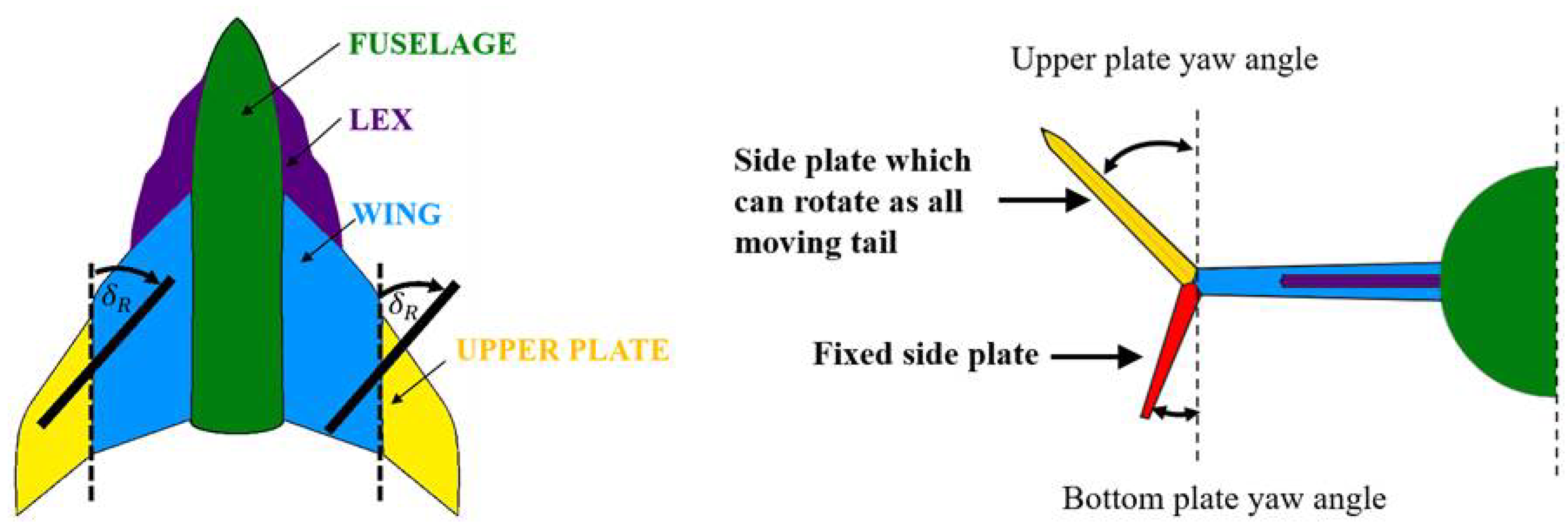
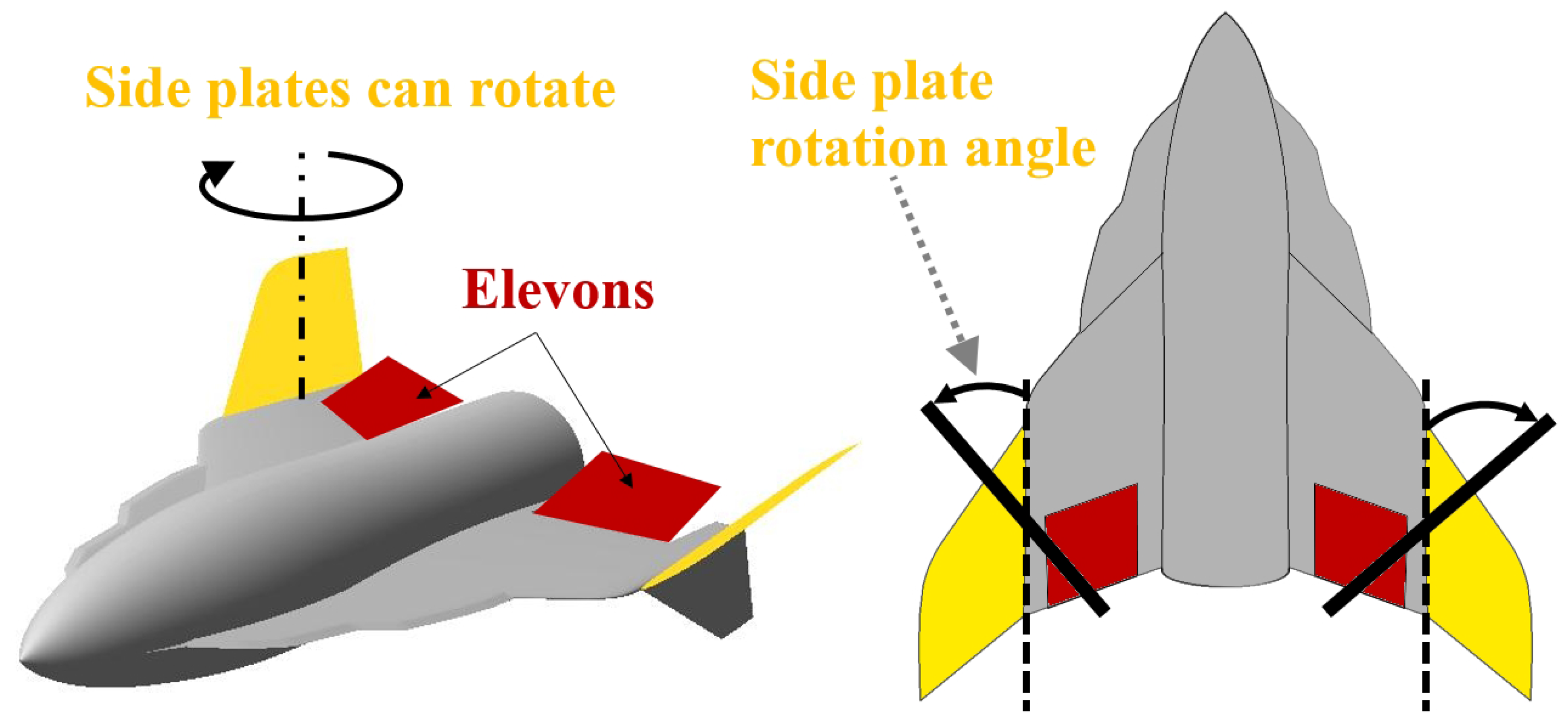
2.1. Rocket Plane Longitudinal Control

The second unusual solution that distinguishes the rocket plane from other designs is a control surfaces arrangement; the rocket plane is equipped with elevons and side plates on the wingtips which can rotate (Figure 2).
The side plates can control motion in two channels: the pitch motion when they are deflected in a symmetrical way or a yaw motion when they are deflected in an asymmetrical way [27]. This concept of control allows for flight on low and high angles of attack, as well as in a wide range of Mach numbers [28]. In addition to the aerodynamic control surfaces, the rocket plane is equipped with a set of rocket maneuvers engines that are going to be responsible for the vehicle control when the control surfaces are ineffective.

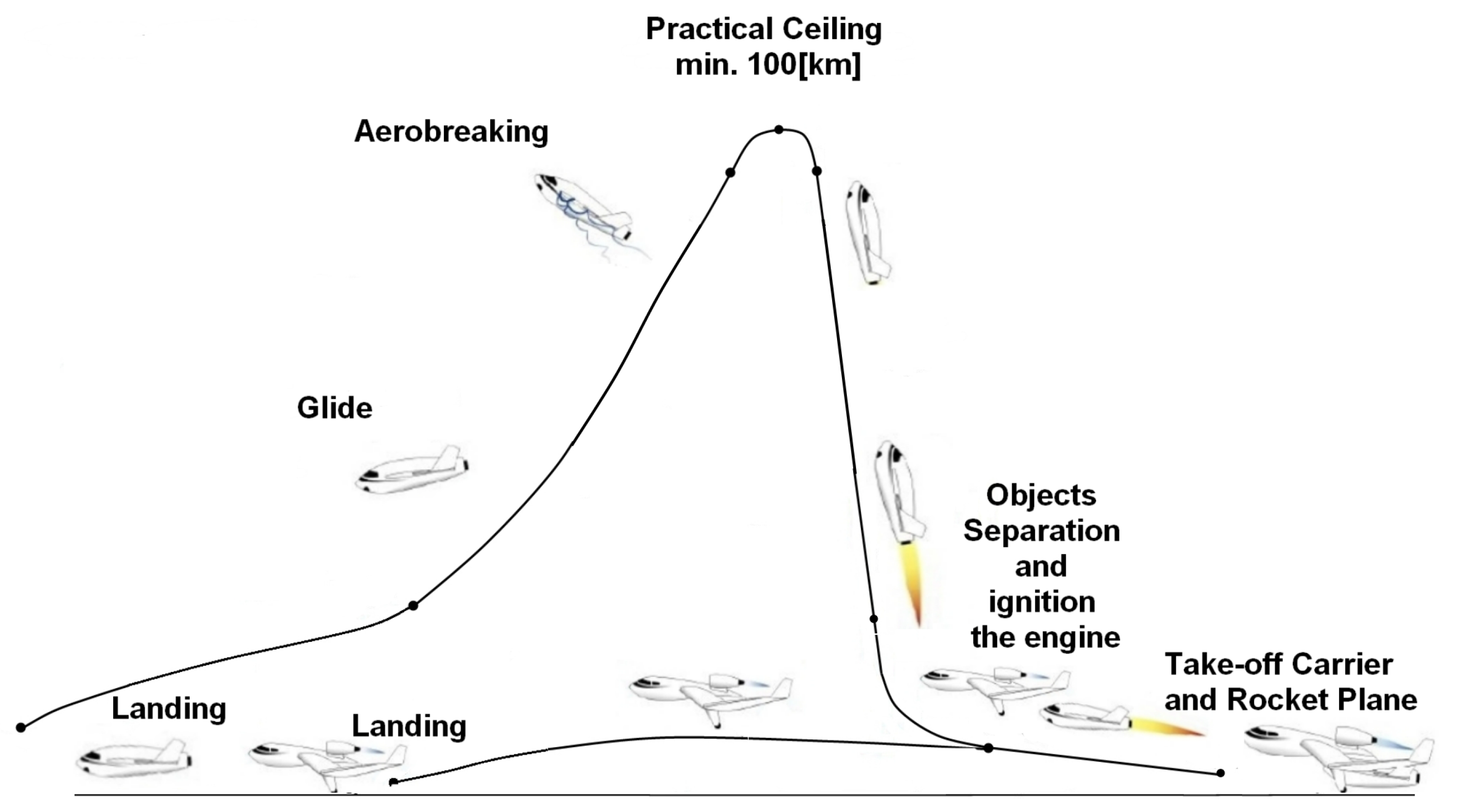
2.2. Mission Profile

The Modular Airplane System mission profile (Figure 3) assumes the following phases: horizontal take-off, climb, vehicles separation, mother plane return flight, rocket plane engine ignitions, rocket plane climb, engine shutdown, ballistic flight, rocket plane return flight, and horizontal landing. The rocket plane flight apogee is above the Karman line.
Due to the forces increment associated with the LEX, the rocket plane sink rate can be reduced which helps with the vehicle braking. Due to a small initial speed, the problem with the excessive heat of the sharp leading edge should not occur. Moreover, the LEX increases the stall angle of attack and allows flight in post-stall conditions.
Due to the application for manned flights, the problem of G-loads must be addressed for the presented concept. Two phases are going to be critical. First, the highest value of G-loads are expected after the rocket plane separates from the carrier. The impact of the separation speed on the maximum G-loads was investigated in [29]. It was concluded that the FAA requirements are possible to be met for this phase. The second critical point occurs during the return flight when the rocket plane needs to transit from a flight at the high angles of attack to low angles of attack. To ensure a safe flight regarding high angles of attack, both elevons and side plates need to be deflected; then, during the transition process, the side plates go back to a neutral (not deflected) position. The rocket plane behavior for such a transition at subsonic speed was investigated using numerical simulations and flight tests of scaled model [29]. The preliminary results showed that the FAA recommendations regarding G-loads are met. Moreover, G-loads also affect requirements regarding the stiffness of the vehicle’s structure. Keeping the G-loads on a low level helps reduce the weight of the structure, which ultimately helps with reducing the cost of the flight.

2.3. Rocket Plane Geometrical Parameters

The rocket plane’s geometrical data are presented in Table 1. All results presented in this paper were obtained for this reference data. It was assumed that the rocket plane’s moment of inertia is not affected by the control surfaces deflection. In addition, any change of the rocket mass due to use of the maneuvers rocket motors, at the beginning of the re-entry flight, was neglected as well.

3. Problem Definition

For the return flight, from the rocket plane control point of view, the following phases can be distinguished: flight at very high altitudes where the air density and/or airspeed are too low to use aerodynamic control surfaces: the only possible way of control are rocket motors. The second phase is when both aerodynamic control surfaces and rocket motors work together. Those two phases are out of the scope of this paper. The next phase is when only the aerodynamic control surfaces are used for the rocket plane control. The rocket plane flies at high angles of attack and with supersonic speed; therefore, both elevons and side plates are engage in the pitch control. The last phase is flight at low altitudes when elevons are sufficient to ensure the rocket plane pitch control. The main research question is how the rocket plane responds to control, and how the initial rocket plane orientation and speed affect the flight parameters. In this study, the most important parameters are Mach number and G-load. According to the project assumptions the rocket plane is not going to be equipped with a heavy thermal shield; therefore, keeping the Mach number on the lowest possible level is essential. In addition, as it was mentioned earlier due to the manned application, the FAA recommendations regarding the G-loads must be met.
The research includes a few types of calculations and simulations. The first set of calculations is going to be related to altitudes which are relatively low for a rocket plane but higher than a typical aircraft flight level. The goal of these calculations is to establish the range of altitudes and speeds (supersonic regime) in which the rocket plane can achieve the trim condition. Then, simulations of the rocket plane response to impulse elevator deflection are going to be performed to investigate the maximum G-load. In addition, for altitudes where the rocket plane can be in trim condition the dynamic stability is going be analyzed. The next set of simulations is going to consider the flight on altitudes where flight in a trim condition is not possible. A different initial speed and vehicles attitudes are going to be considered. This part of the study is going to help address the impact of the initial flight condition (after passing the apogee) on the return flight parameters.

4. Numerical Model

The presented study required the adoption of a number of assumptions regarding mathematical models. The simulation model [30] used for analyses was modified to allow simulations of higher layers of atmosphere. The aerodynamic characteristics were obtained within numerical [31] and experimental investigations [32]. In addition, some extra assumptions had to be considered regarding the control surfaces, which differ compared to the classical layout.

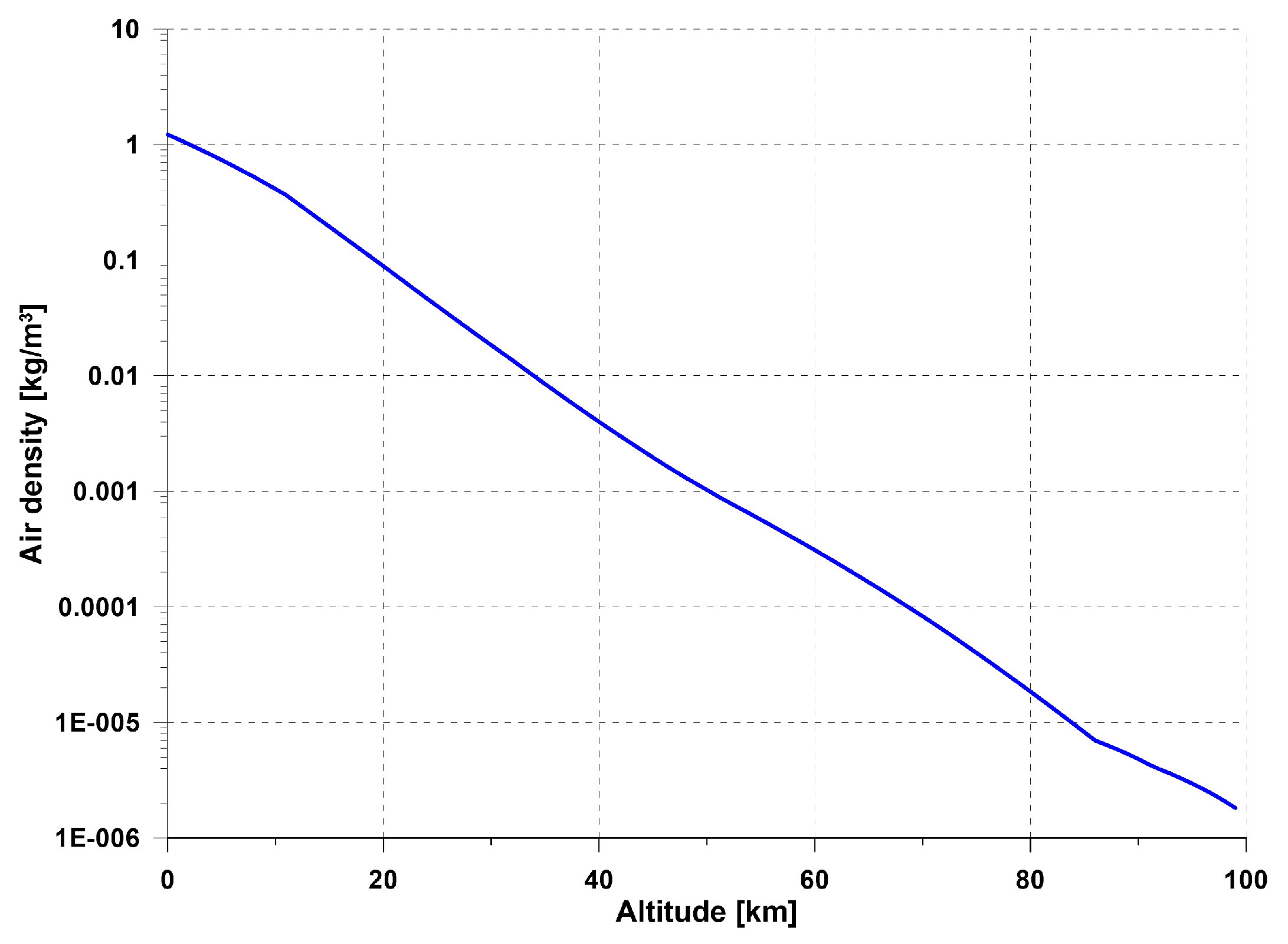
4.1. Model of Atmosphere
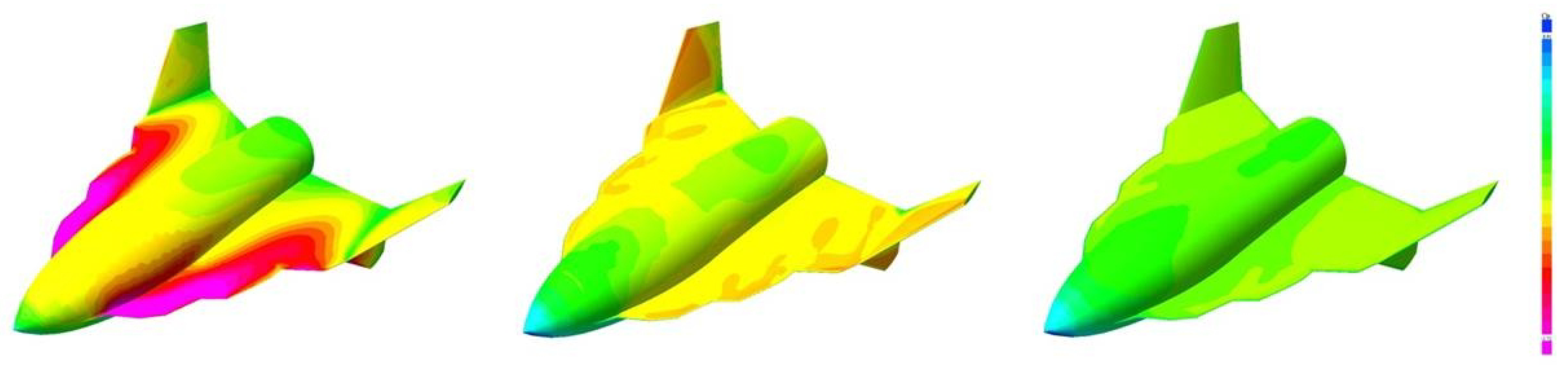
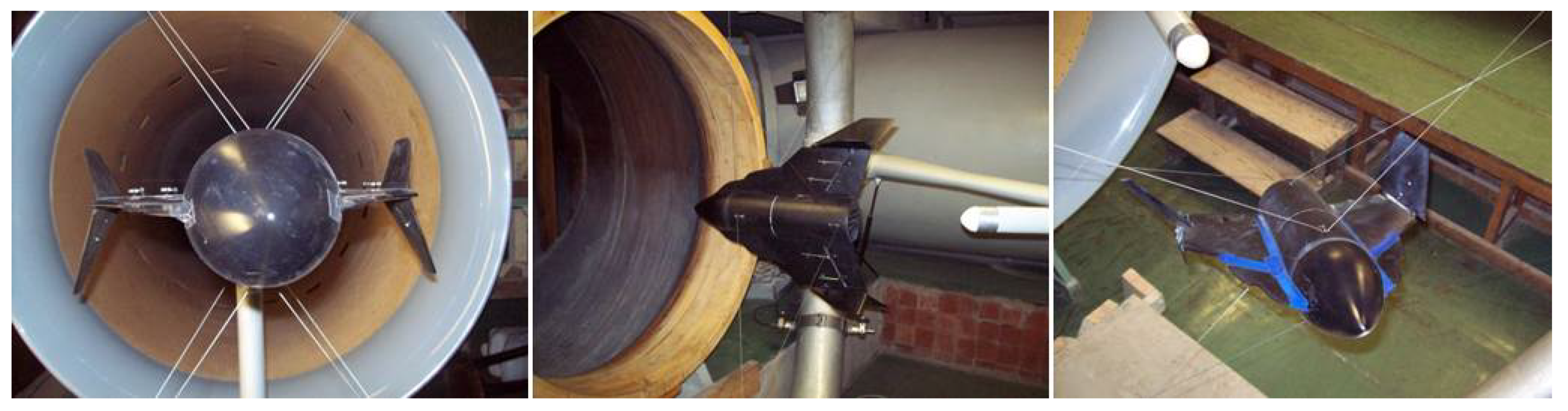
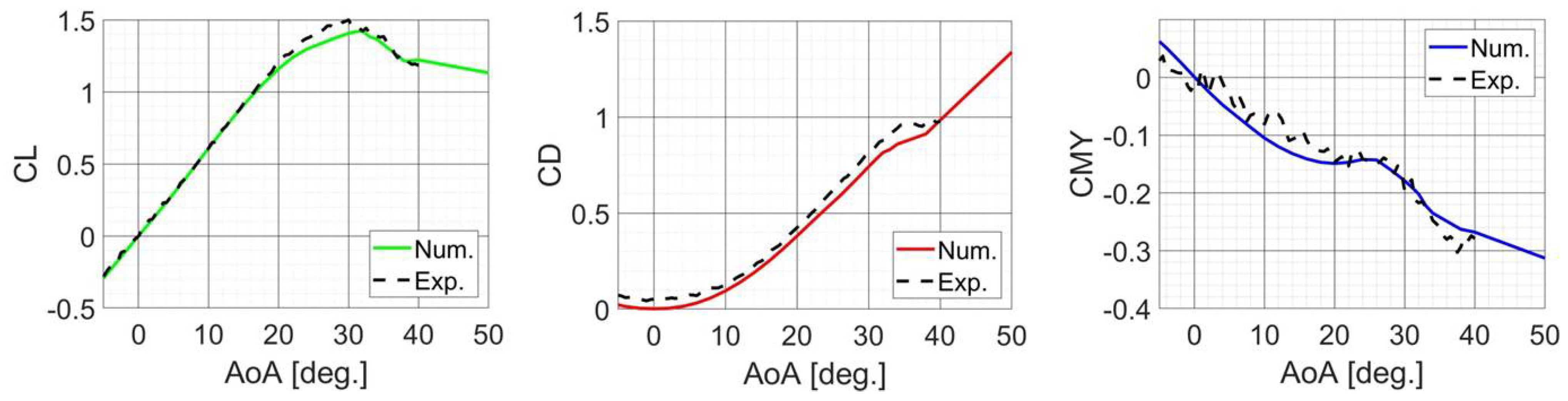
The International Standard Atmosphere model, as well as U.S. Standard Atmosphere [33], includes altitudes up to 86 km. The model embedded in SDSA (Simulation and Dynamic Stability Analysis, ver. 2020, rev. 1004) software [30,34] originally was limited to higher stratosphere. Simulations conducted in this paper required much higher levels, so the model was extended. Air density, which for higher levels is drastically smaller, is crucial. The change in air density as a function of altitude presented in Figure 4 shows that air density at the highest level is about a million times less than air density at sea level. During all simulations, the atmospheric condition was assumed as calm (no turbulence).

4.2. Aerodynamics

The aerodynamic forces and moments coefficients required to perform analysis of the rocket plane stability and flight simulations were computed with use of the CFD (Computing Fluid Dynamics) software. The subsonic results were then experimentally verified by the wind tunnel tests. To perform these CFD analyses, the MGAERO (ver. 3.4) [35] software was used, which is a commercial software that uses the Euler code with multigrid acceleration in the computation of the aerodynamic coefficients of arbitrary configuration [36]. Such software allows us to obtain aerodynamic characteristics for supersonic speed in a fairly effective computation time; however, due to the inviscid flow, the vortex breakdown is not modeled.
The rocket plane CFD model consists of 36,968 on body panels and seven levels of multigrid, which results in 2,930,856 off-body panels. The deflection of the side plates and elevons were modeled by a rotation of control surfaces in the numerical model according to an appropriate axis [31]. An example pressure distribution for the model without deflected elevons and side plates is presented in Figure 5.
As mentioned, selected CFD results were verified in the wind tunnel test. The experimental tests campaign was conducted in the Warsaw University of Technology aerodynamics laboratory (Faculty of Power and Aeronautical Engineering). A closed-circuit subsonic wind tunnel with a 1.16m diameter open measure test section was used. The dedicated model of the rocket plane was built in 1:15 scale. The model was equipped with the control surfaces that were deflected during the tests. The model was attached in the wind tunnel using wires which passed through muffs in the fuselage (Figure 6). The wind tunnel is equipped with the Witoszyński type balance [37] with a digital data acquisition system.
During the tests, data such as lift, drag, and pitching moment coefficients were collected at a free stream velocity of 40 m/s, corresponding to the Reynolds number of about Re = 0.7 × 10 6 (calculated based on the MAC of the wing). The measurements were taken in an aerodynamic coordinate system for the reference point, which was located at 21% of the wing MAC, the assumed center of gravity position of the rocket plane. All characteristics were measured for the range of angles of attack from −5° to +40° [32]. Experimental investigations for higher AoA and/or higher Mach numbers were not possible due to facility limitations.
The results of the wind tunnel tests were compared with the results of numerical calculations (Figure 7). The lift force coefficient reveals a good accordance with numerical results obtained for the almost the whole range of AoA. It is worth noticing that experiment revealed a higher value of the lift coefficient at the critical AoA then the CFD analysis. The experimental drag coefficient reveals a good accordance with computational results but only for the medium AoA. The reason for the worse accordance of small values of AoA is the omission of friction drag in numerical computations. Therefore, the aerodynamic drag characteristics that were then used for numerical simulation tests were modified in the range of small AoA values to obtain a reasonable value of minimum drag.

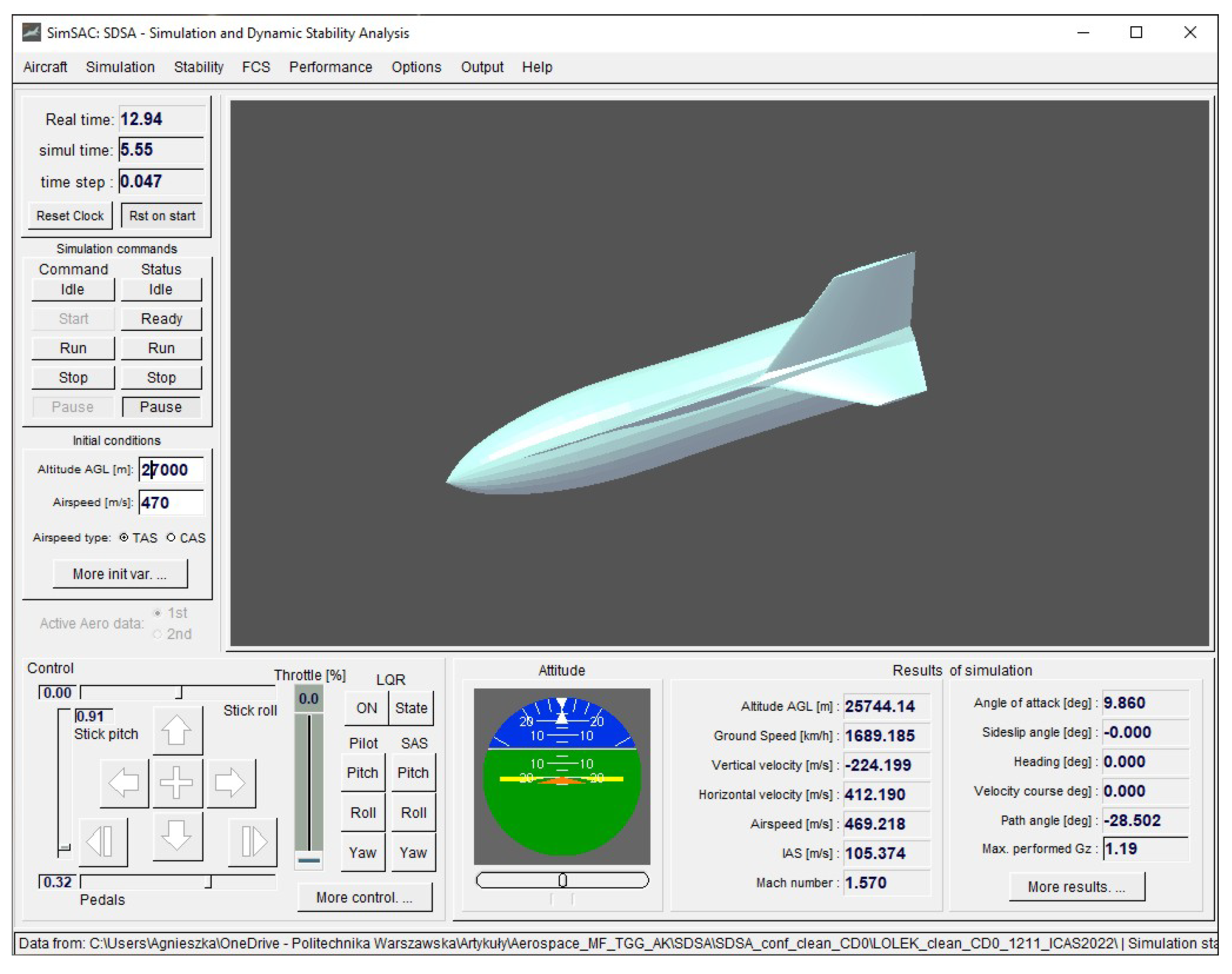
4.3. Flight Simulations

Simulation calculations were performed using the SDSA [30,34] software, in which a full non-linear 6DoF model of the aircraft motion was implemented (Figure 8). The flight parameters can be recorded for further postprocessing. The input consists of aerodynamic and control characteristics (all components), and geometry and inertia data.
The SDSA 6DoF simulation allows the analysis of the response to control with the unit step function or impulse function. Because the software assumes one control surface (device) per axis (one for pitch control, one for yaw control, and one for roll control); therefore, to account for the effects of both the elevons and side plate, the elevator characteristics are the equivalent of the sum of both of the controls characteristics and simulated by one deflection angle. For example, the deflection of the elevator by −10° means that both the elevons and side plates are deflected by −10°. The simulation in the SDSA can be performed for initial condition which does not correspond to the trim condition and state parameters such as angle of attack or path angle can be set up by the user. Those functionalities were used to perform simulations presented in this paper.
The SDSA software was used in other projects where the software outcomes were compared with data recorded in a flight campaign [38], as well as for case of aircraft designed in the flying wing configuration [39]. A good consistency of results was obtained.

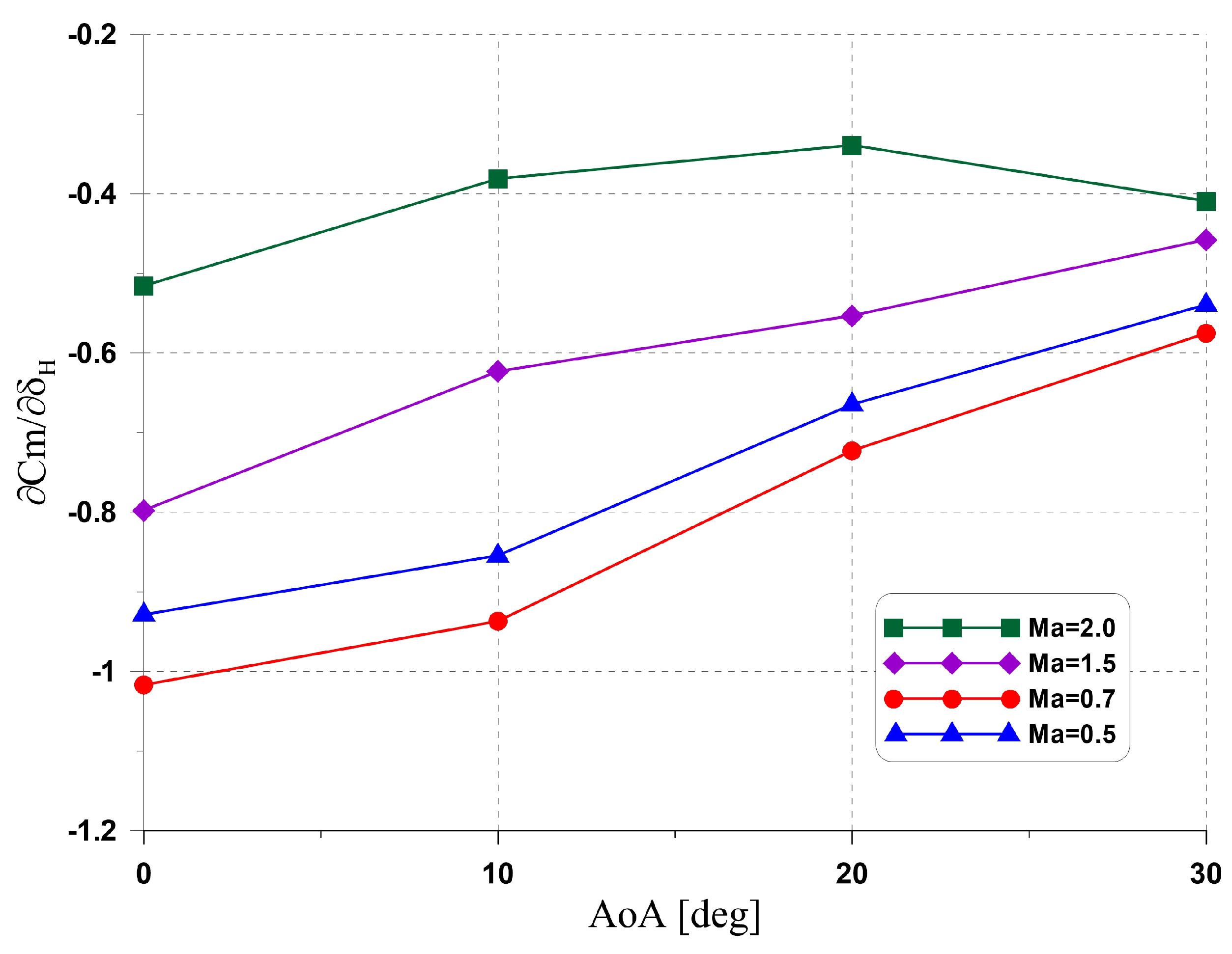
4.4. Control Derivatives

The rocket plane is equipped with side plates and elevons. In all simulations presented in this paper, it was assumed that both side plates and elevons are deflected simultaneously by the same angle. The derivative of the pitching moment in respect to angle of attack for selected Mach numbers is presented in Figure 9. For low AoA, the reduction between subsonic and supersonic speed is more severe than for high AoA. During the simulation, the change of the pitching moment and lift coefficient due to the elevator deflection were taken into account while the impact of the drag force was neglected.

5. Results

This section presents results obtained by the SDSA software for different scenarios, including how the change of the rocket plane initial orientation affected the trajectory. In particular, the effect of the initial speed on the maximum flight parameters and the rocket plane response to control, as well as results for case when the rocket plane travels with supersonic speed and the air density is sufficient to obtain the trim condition, are presented.

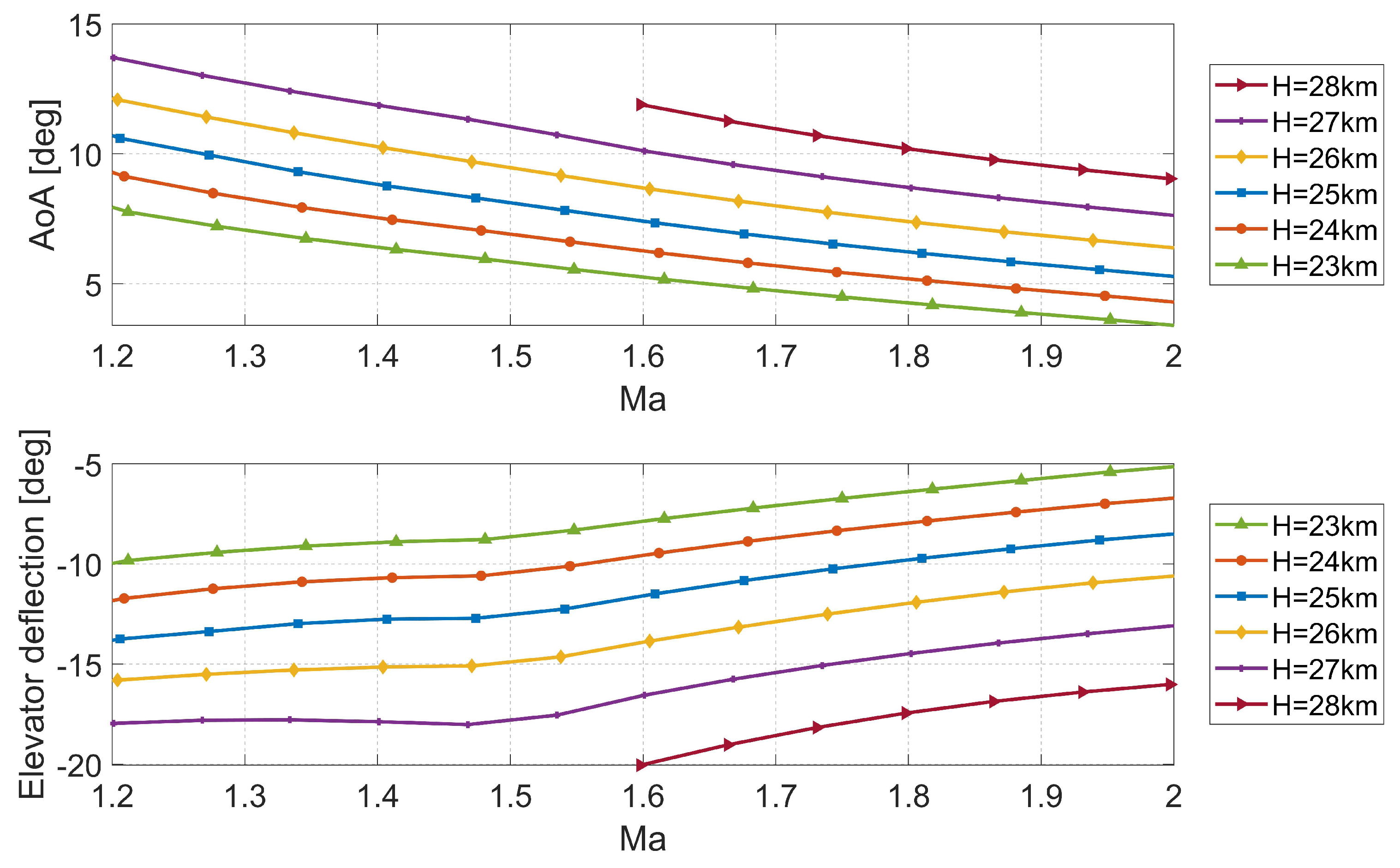
5.1. Results for Trimmed Flight

The results of trim calculations for the supersonic speed regime for the altitude between 23 to 28 km are presented in Figure 10. The results were calculated using SDSA software which solved the problem of equilibrium of forces and moments. The maximum elevator deflection (simultaneous deflection of elevons and side plates) is equal to −20° (both elevons and side plate are deflected by −20°. Obtaining the trim condition within considered Ma range, for altitude equal or higher than 29 km would require bigger elevator deflection than it can be obtained. The elevons are deflected up while the trailing edge of each side plate is rotated inward; therefore, the deflection is limited due to a possible crash of control surfaces.
The simulation results of rocket plane response to control are presented in Figure 11 (plot on the left). The simulations were performed by the SDSA software under the assumption that at time equal to zero the rocket plane is in trim condition for a selected speed (initial Ma) then after 1 s, the elevator was deflected by 10°, as presented in Figure 11 (plot on the right). During the simulation, the maximum value of the G-load in z direction, caused by the elevator deflection was recorded. This impulse function represents a brutal control case.

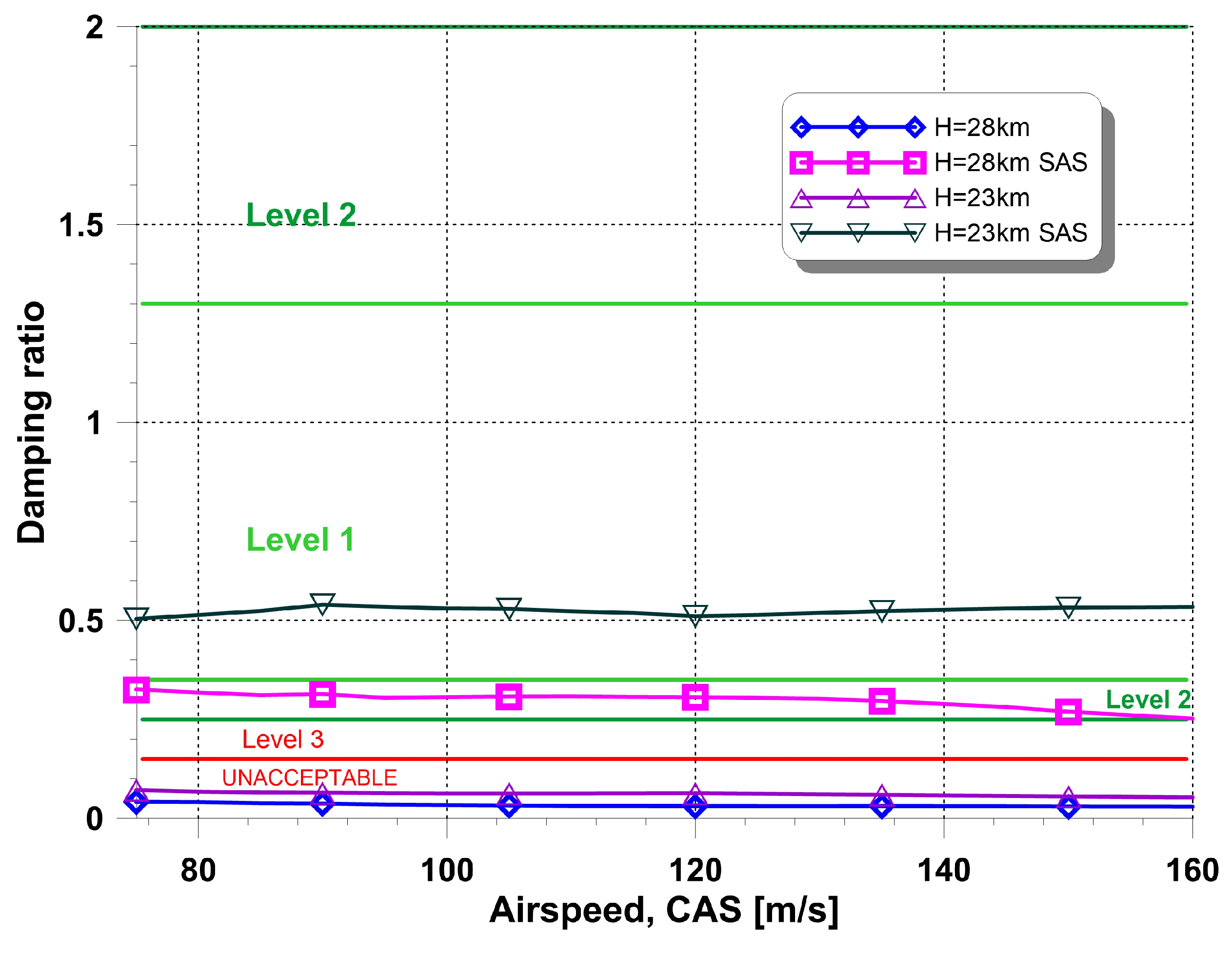
5.2. Dynamic Stability

The next step in any aircraft design is the stability analysis. For such an unconventional layout, this step is particularly important [40]. Dynamic stability analysis was carried out for longitudinal modes. A typical approach based on small perturbations was used, using the SDSA [34] package for calculations. The first mode to be analyzed is the so-called Short Period oscillations, for which they are required to be strongly damped over the entire airspeed and altitude range. Figure 12 presents the results of analysis performed for fixed control surfaces and with the Stability Augmentation System (SAS) against the background of MIL [41] criterion. It shows that for both heights of flight oscillations are damped, however, not strongly enough without SAS, which was expected for tailless configuration.
The second analyzed mode, Phugoid, is not so critical and usually it is enough if it is not too unstable. The results obtained within the numerical analysis show that Phugoid is well damped (Figure 13).
An additional effect was shown by the simulation results (using the non-linear model [30]). Both the frequency and the damping obtained from the eigenvalue analysis strongly differ from the results of the non-linear model (simulation—Figure 14). This is due to the fact that with a long period of oscillation, the requirements of small disturbances are not met. The differences are presented in Table 2.

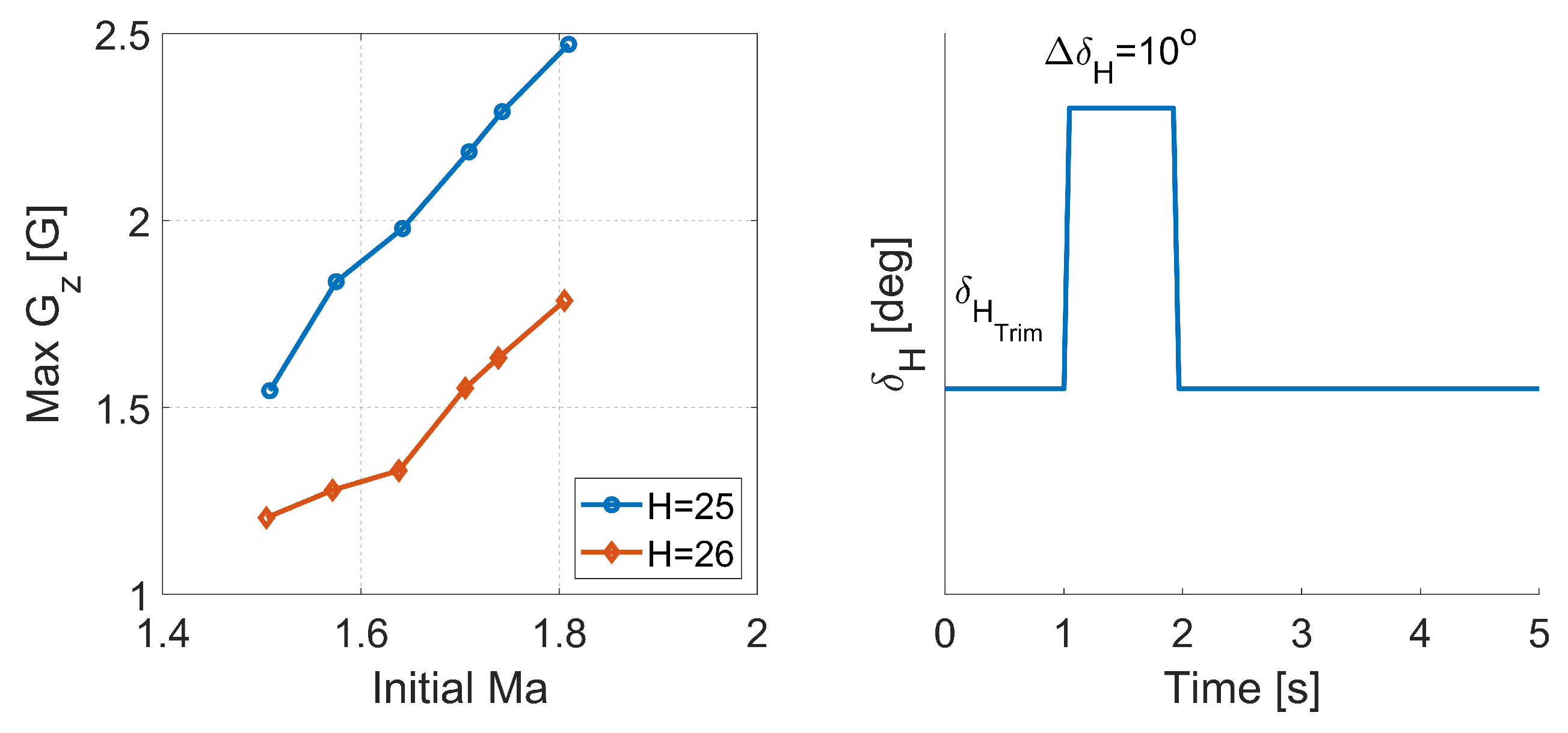
5.3. Results of Flights Simulations

The first set of simulations was performed under the assumption that the rocket plane is in free fall from 80 km with different initial condition (speed, AoA, pitch angle); for all simulations, the elevator was fixed and deflected by −20°. A typical shape of the Ma and G-load profile is presented in Figure 15. For each simulation, the maximum of the Ma and G-loads were recorded; then, the impact of selected initial conditions on those parameters was plotted.
Figure 16 shows the impact of the initial Mach number on the maximum flight parameters. Higher initial speed results in higher maximum Mach number; on the other hand, higher speed is associated with greater forces which help to reduce maximum G-load.
In the next step, the focus was on the analysis of the impact of the initial AoA and pitch angle on the maximum flight parameters (Ma, G-load). The simulation results are summarized in Figure 17 and Figure 18. The effect on the Mach number is negligible, while a minor effect on the G-load can be observed, regardless of the considered altitude (80 km or 60 km). Taking into account the FAA recommendation, the effect on G-load is not satisfactory.
Next, the aircraft response to the elevator deflection for high altitudes was investigated. All simulations started at an altitude equal to 80 km and with initial speed which corresponded to Ma = 2.0 then at selected altitudes the impulse elevator deflection was applied. The results are presented in Figure 19 and Figure 20. For the purpose of the comparison, the time of the simulation was altered; the time when the elevator was deflected was shifted to zero. The noticeable impact of the elevator deflection on the angle of attack occurs for altitude around 55 km. In all simulations, the G-load change due to the elevator deflection, which was so small that there was no risk that the FAA recommendations is going to be exceeded. More results regarding the elevator deflection can be found in [42].
The oscillations that were induced have no effect on the maximum G-load; therefore, to investigate a possibility of its reduction, simulations of step elevator deflection were performed. The results of maximum G-load recorded before and after the step deflection are presented in Figure 21 (graph on the left), while an example of the G-load distribution for the response to a step control is shown in graph on the right.

6. Conclusions

In this paper, the rocket plane for suborbital manned flights was considered. The study focused on numerical analyses and simulations related to the return flight. The first results of equilibrium conditions and dynamic stability analysis were presented. Then, the response of the rocket plane to the control was investigated. Next, the outcomes of the flight simulations for altitudes where obtaining the trim is not possible were inspected. Based on the presented results the following conclusions can be drawn:
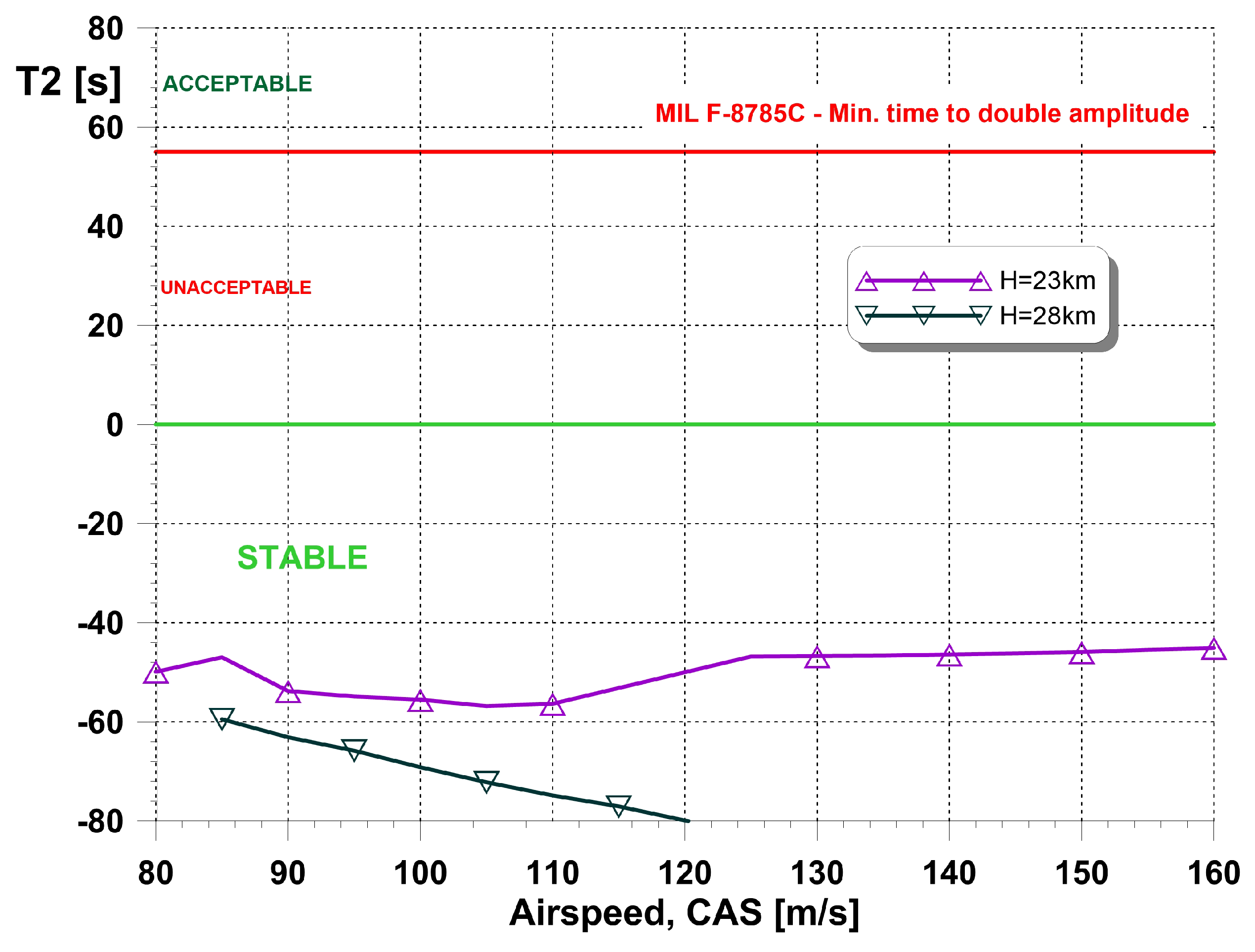
  • For altitudes between 23 to 28 km and a supersonic speed regime, the short period damping is insufficient and application of the Stability Augmentation System (SAS) is recommended. A proper selection of gain resulted in shifting the damping to the Level 1 (according to MIL specification).
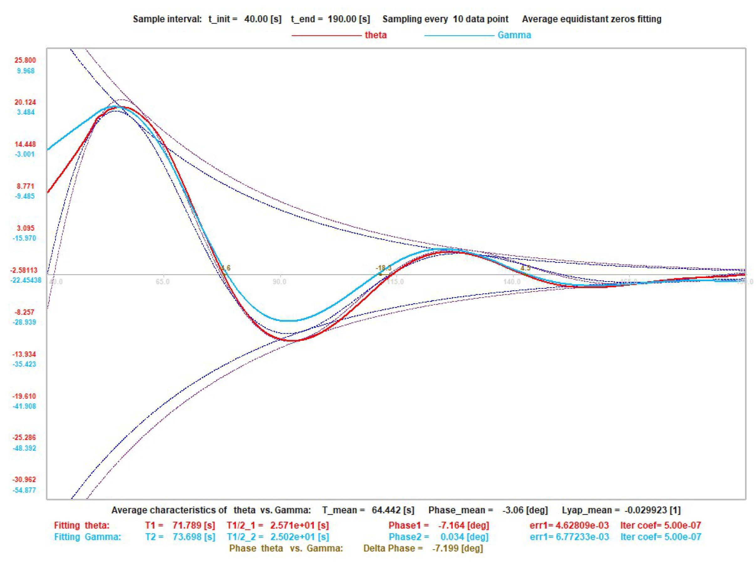
  • In the case of a vehicle which glides at supersonic speed, the phugoid motion parameters should be investigated with the use of flight simulation, rather than solving the eigenvalue problem. This is associated with the change in atmosphere parameters vs. altitude, which significantly affect the oscillation characteristics. In the presented case, the difference in the period value is almost five times.
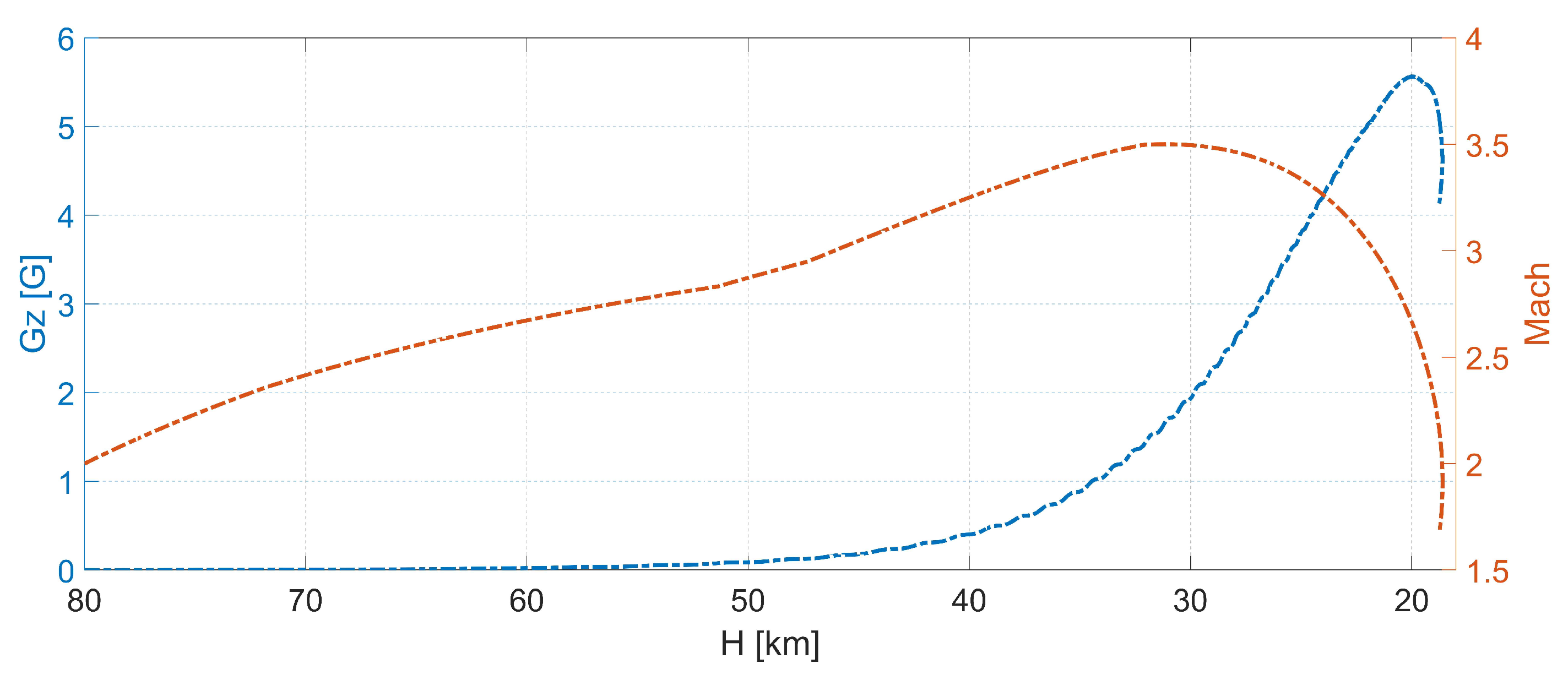
  • The maximum Mach number and maximum G-load occur at different altitudes. The highest values of the Ma were noticed at between 30–35 km, while the highest values of G-load were recorded around 20 km.
  • In the case of the rocket plane response to control for very high altitudes and supersonic speed, the impact of the impulse deflection of the elevator on angle of attack starts to be visible around 55 km. The deflection increases the oscillations amplitude, but the oscillations are damped for all considered altitudes.
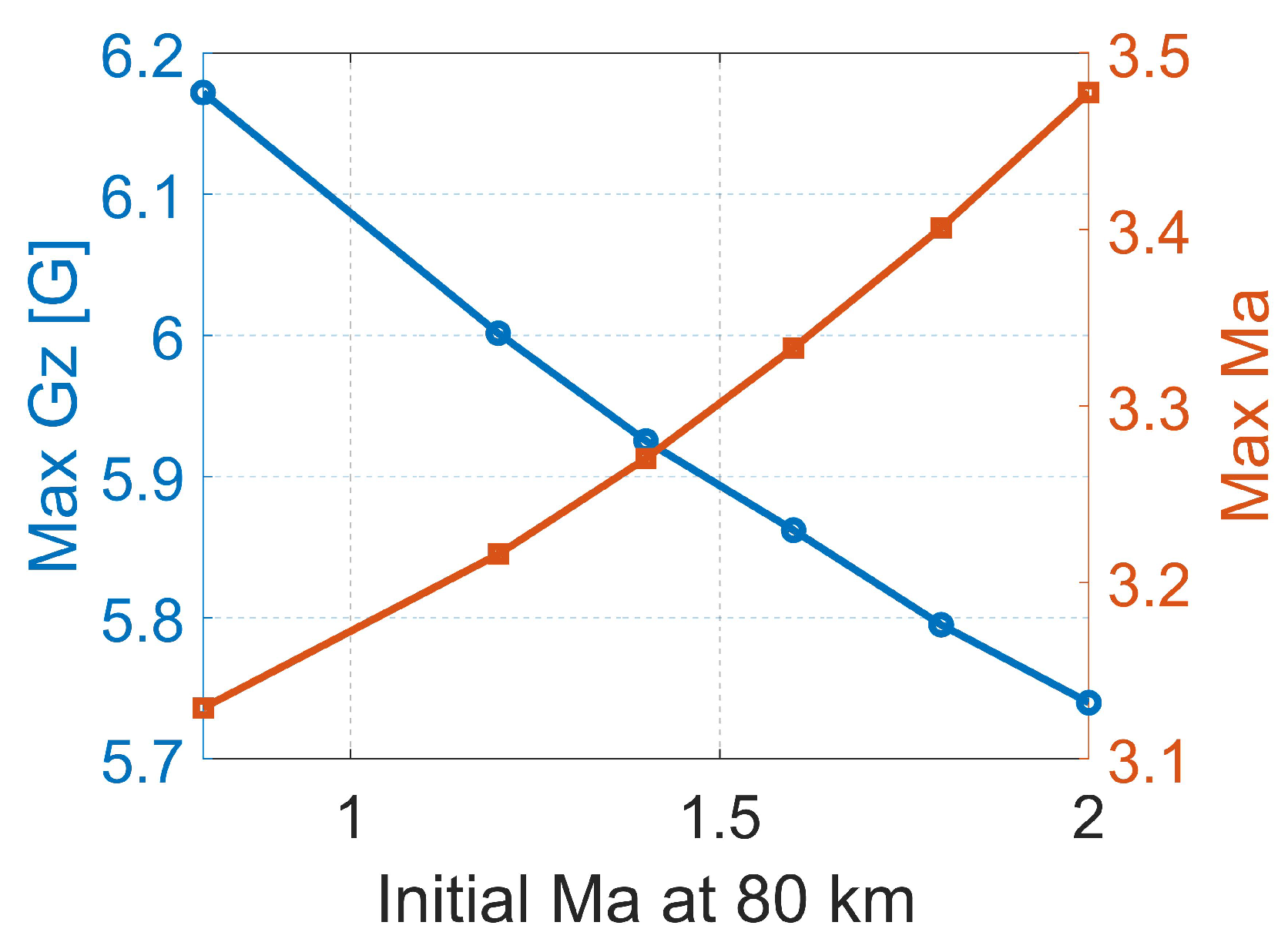
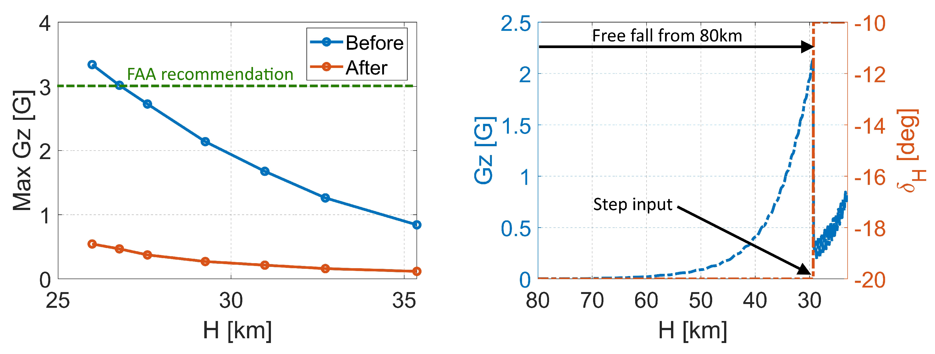
  • The initial speed and orientation of the rocket plane have negligible effect on the maximum Mach number and minor impact on G-loads. To reduce the G-load, the angle of attack must be reduced at low altitudes below approximately 27 km.

7. Further Work

In the future, it is planned to perform a simulation with a more sophisticated rocket aircraft control model and taking into account asymmetric flight conditions. The implementation of both rocket motors and aerodynamic control surfaces is necessary to design the trajectory that satisfies the control and stability constraints, as well as G-load recommendation.

Author Contributions

Conceptualization, A.K., M.F.; methodology, A.K., M.F., T.G.-G.; software, T.G.-G.; resources, A.K.; investigation, A.K., M.F., T.G.-G.; writing—original draft preparation, A.K., M.F., T.G.-G.; writing—review and editing, A.K., M.F., T.G.-G.; supervision, T.G.-G. All authors have read and agreed to the published version of the manuscript.

Funding

This research received no external funding.

Institutional Review Board Statement

Not applicable.

Informed Consent Statement

Not applicable.

Conflicts of Interest

The authors declare no conflict of interest.

References

  1. Inspiration4. 2023. Available online: https://inspiration4.com/mission (accessed on 2 April 2023).
  2. Axiom Space. 2023. Available online: https://www.axiomspace.com/ax1 (accessed on 2 April 2023).
  3. Polaris. 2023. Available online: https://polarisprogram.com/dawn/ (accessed on 2 April 2023).
  4. Ansari Prize. 2023. Available online: https://www.xprize.org/prizes/ansari (accessed on 24 March 2023).
  5. Sarigul-Klijn, M.; Sarigul-Klijn, N. Flight Mechanics of Manned Sub-Orbital Reusable Launch Vehicles with Recommendations for Launch and Recovery. In Proceedings of the 41st Aerospace Sciences Meeting and Exhibit, Reno, NV, USA, 6–9 January 2003; American Institute of Aeronautics and Astronautics: Reston, VA, USA, 2003. [Google Scholar] [CrossRef]
  6. Blue Origin. 2023. Available online: https://www.blueorigin.com/new-shepard/fly/ (accessed on 24 March 2023).
  7. Virgin Galactic Spaceflight. 2023. Available online: https://www.virgingalactic.com/#horizontal-scroll. (accessed on 24 March 2023).
  8. Scaled Composites. 2023. Available online: https://www.scaled.com/portfolio/spaceshipone/ (accessed on 24 March 2023).
  9. Antuñano, M.J.; Baisden, D.L.; Davis, J.; Hastings, J.D.; Jennings, R.; Jones, D.; Jordan, J.L.; Mohler, S.R.; Ruehle, C.; Salazar, G.J.; et al. Guidance for MedicalScreening of CommercialAerospace Passengers; Techreport DOT/FAA/AM-06/1; FAA, Office of Aerospace Medicine: Washington, DC, USA, 2006.
  10. Davis, J.R.; Johnson, R.; Stepanek, J.; Fogarty, J.A. Fundamentals of Aerospace Medicine, 4th ed.; Wolters Kluwer Health Adis (ESP): Philadelphia, PA, USA, 2011. [Google Scholar]
  11. Clément, G. Fundamentals of Space Medicine; Springer: New York, NY, USA, 2011. [Google Scholar] [CrossRef]
  12. Wang, K.; Zhang, B. Multiobjective trajectory optimization for a suborbital spaceplane using Directed Search Domain approach. Aerosp. Sci. Technol. 2018, 77, 713–724. [Google Scholar] [CrossRef]
  13. Charbonnier, D.; Vos, J.; Marwege, A.; Hantz, C. Computational fluid dynamics investigations of aerodynamic control surfaces of a vertical landing configuration. CEAS Space J. 2022, 14, 517–532. [Google Scholar] [CrossRef]
  14. Jenie, Y.I.; Suarjaya, W.W.H.; Poetro, R.E. Falcon 9 Rocket Launch Modeling and Simulation with Thrust Vectoring Control and Scheduling. In Proceedings of the 2019 IEEE 6th Asian Conference on Defence Technology (ACDT), Bali, Indonesia, 13–15 November 2019. [Google Scholar] [CrossRef]
  15. Pruzan, D.; Mendenhall, M.; Rose, W.; Schuster, D. Grid Fin Stabilization of the Orion Launch Abort Vehicle. In Proceedings of the 29th AIAA Applied Aerodynamics Conference, Honolulu, Hawaii, USA, 27–30 June 2011; American Institute of Aeronautics and Astronautics: Reston, VA, USA, 2011. [Google Scholar] [CrossRef]
  16. Tripathi, M.; Sucheendran, M.M.; Misra, A. Experimental analysis of cell pattern on grid fin aerodynamics in subsonic flow. Proc. Inst. Mech. Eng. Part G J. Aerosp. Eng. 2019, 234, 537–562. [Google Scholar] [CrossRef]
  17. Schülein, E.; Guyot, D. Novel High-Performance Grid Fins for Missile Control at High Speeds:Preliminary Numerical and Experimental Investigations. In Proceedings of the Meeting Proceedings RTO-MP-AVT-135, Neuilly-sur-Seine, France, 15–18 May 2006. [Google Scholar]
  18. Olejnik, A.; Kiszkowiak, Ł.; Zalewski, P.; Dziubiński, A. Low-Cost Satellite Launch System—Aerodynamic Feasibility Study. Aerospace 2022, 9, 284. [Google Scholar] [CrossRef]
  19. Sahbon, N.; Jacewicz, M.; Lichota, P.; Strzelecka, K. Path-Following Control for Thrust-Vectored Hypersonic Aircraft. Energies 2023, 16, 2501. [Google Scholar] [CrossRef]
  20. Chyu, W.J.; Cavin, R.K.; Erickson, L.L. Static and Dynamic Stability Analysis of the Space Shuttle Vehicle-Orbiter; NASA Technical Paper TP 1179; NASA Langley: Hampton, VA, USA, 1978.
  21. Aprovitola, A.; Luspa, L.; Pezzella, G.; Viviani, A. Optimal design of a next generation high-lift reusable re-entry vehicle. In Proceedings of the 32th Congress of the International Council of the Aeronautical Sciences, ICAS 2021, Shanghai, China, 6–10 September 2021. [Google Scholar]
  22. Bae, S.; Shin, H.S.; Savvaris, A.; Vaios, L.; Tsourdos, A. Multi-objective suborbit/orbit trajectory optimisation for spaceplanes. Acta Astronaut. 2020, 170, 431–442. [Google Scholar] [CrossRef]
  23. Figat, M.; Galiński, C.; Kwiek, A. Modular Aeroplane System. A Concept and Initial Investigation. In Proceedings of the 28th Congress of the International Council of the Aeronautical Sciences, ICAS, Brisbane, Australia, 23–28 September 2012. [Google Scholar]
  24. Galiński, C.; Goetzendorf-Grabowski, T.; Mieszalski, D.; Stefanek, L. A concept of two-staged spaceplane for suborbital tourism. Trans. Inst. Aviat. 2007, 191, 33–42. [Google Scholar]
  25. Lamar, J.E. The Use and Characteristics of Vortical Flows Near a Generating Aerodynamic Surface: A Perspective. Prog. Aerosp. Sci. 1998, 34, 167–217. [Google Scholar] [CrossRef]
  26. Polhamus, E.C. A Concept of the Vortex Lift of Sharp-Edge Delta Wings Based on a Leading-Edge-Suction Analogy; NASA Technical Note NASA-TN-D-3767; NASA Langley: Hampton, VA, USA, 1966.
  27. Kwiek, A.; Figat, M. An investigation into directional characteristics of the rocket plane in a tailless configuration. CEAS Space J. 2022, 1–14. [Google Scholar] [CrossRef]
  28. Kwiek, A. Study on Control and Stability of the Rocket Plane to Space Tourism. In Proceedings of the 29th Congress of the International Council of the Aeronautical Sciences, ICAS, St. Petersburg, Russia, 7–12 September 2014. [Google Scholar]
  29. Kwiek, A.; Galinski, C.; Bogdański, K.; Hajduk, J.; Tarnowski, A. Results of simulation and scaled flight tests performed on a rocket-plane at high angles of attack. Aircr. Eng. Aerosp. Technol. 2021, 93, 1445–1459. [Google Scholar] [CrossRef]
  30. Goetzendorf-Grabowski, T.; Mieszalski, D.; Marcinkiewicz, E. Stability analysis using SDSA tool. Prog. Aerosp. Sci. 2011, 47, 636–646. [Google Scholar] [CrossRef]
  31. MGAERO. A Cartesian Multigrid Euler Code for flow Around Arbitrary Configurations—User’s Manual Version 3.1.4; Analytical Methods, Inc.: Redmond, WA, USA, 2001. [Google Scholar]
  32. Kwiek, A.; Figat, M. LEX and wing tip plates’ interaction on the Rocket Plane in tailless configuration. Aeronaut. J. 2016, 120, 255–270. [Google Scholar] [CrossRef]
  33. Techreport NOAA-S/T 76-1562; U.S. Standard Atmosphere. National Oceanic and Atmospheric Administration: Washington, DC, USA, 1976.
  34. SDSA—Simulation and Dynamic Stability Analysis Application, Warsaw University of Technology, Poland. 2020. Available online: https://www.meil.pw.edu.pl/add/ADD/Teaching/Software/SDSA (accessed on 1 May 2021).
  35. Analytical Methods, Inc. MGAERO—Cartesian Grid Euler Method. 2018. Available online: https://www.amiaerollc.com/Software.html (accessed on 1 May 2021).
  36. Mavriplis, D.J. Three-dimensional unstructured multigrid for the Euler equations. AIAA J. 1992, 30, 1753–1761. [Google Scholar] [CrossRef]
  37. Witoszyński, C. Travaux de L’Institut Aerodynamique de Varsovie; WUT: Warsaw, Poland, 1932; Volume V, (In Polish and French). [Google Scholar]
  38. Goetzendorf-Grabowski, T.; Marcinkiewicz, E.; Galiński, C. Comparison of traditionally calculated stabilitycharacteristics with flight test data of PW-6U sailplane. In Proceedings of the 4th CEAS Air & Space Conference, Linköping, Sweden, 16–19 September 2013; pp. 536–543. [Google Scholar]
  39. Mieloszyk, J.; Tarnowski, A.; Tomaszewski, A.; Goetzendorf-Grabowski, T. Validation of flight dynamic stability optimization constraints with flight tests. Aerosp. Sci. Technol. 2020, 106, 106193. [Google Scholar] [CrossRef]
  40. Goetzendorf-Grabowski, T. Flight dynamics of unconventional configurations. Prog. Aerosp. Sci. 2023, 137, 100885. [Google Scholar] [CrossRef]
  41. MIL-F-8785C—Military Specification Flying Qualities of Piloted Airplanes. 1980. Available online: http://everyspec.com/MIL-SPECS/MIL-SPECS-MIL-F/MIL-F-8785C_5295/ (accessed on 10 April 2023).
  42. Kwiek, A.; Figat, M.; Goetzendorf-Grabowski, T. Preliminary Study on a Design of a Return Flight Trajectory of a Suborbital Vehicle. In Proceedings of the 33rd Congress of the International Council of the Aeronautical Sciences, ICAS, Stockholm, Sweden, 4–9 September 2022. [Google Scholar]
Figure 1. Layout of the rocket plane geometry.
Aerospace 10 00489 g001
Figure 2. Concept of the rocket plane control.
Aerospace 10 00489 g002
Figure 3. Sketch of Modular Airplane System mission profile [23].
Aerospace 10 00489 g003
Figure 4. Air density model for altitude according to the ISA model.
Aerospace 10 00489 g004
Figure 5. Example of Cp distribution for the rocket plane for selected Mach Numbers: Ma = 0.5 (on the left), Ma = 1.2 (in the middle) and Ma = 2.0 (on the right) and Angle of Attack AoA = 20 deg. (without control surfaces deflection).
Aerospace 10 00489 g005
Figure 6. Models of the rocket plane during the wind tunnel campaign (at right: the model with deflected side plates).
Aerospace 10 00489 g006
Figure 7. Comparison of numerical results with the experimental data.
Aerospace 10 00489 g007
Figure 8. SDSA simulation window.
Aerospace 10 00489 g008
Figure 9. Example of derivative of the pitching moment with respect to elevator (sum of the elevons and side plates) deflection. Comparison of the derivatives of selected subsonic and supersonic Mach numbers.
Aerospace 10 00489 g009
Figure 10. Results of SDSA trim computation for the supersonic speed range and altitude range of 23 to 28 km. The black solid line represents the maximum possible deflection of the elevator.
Aerospace 10 00489 g010
Figure 11. Influence of Ma on maximum G-load in case of impulse elevator deflection by 10°.
Aerospace 10 00489 g011
Figure 12. Short Period damping ratio against background of MIL-F-8785C specification [41].
Aerospace 10 00489 g012
Figure 13. Phugoid time to double against background of MIL-F-8785C specification [41].
Aerospace 10 00489 g013
Figure 14. Phugoid simulation (pitch angle θ and path angle γ ) [34].
Aerospace 10 00489 g014
Figure 15. A typical profile of Mach number and G-load recorded by SDSA when simulating the rocket plane free fall with fixed elevator deflection.
Aerospace 10 00489 g015
Figure 16. Impact of the initial speed on maximum Mach number and maximum G-load [42].
Aerospace 10 00489 g016
Figure 17. Effect of initial AoA on maximum G-load and maximum Mach number. The simulations started with Ma = 2.0 at 80 km and 60 km.
Aerospace 10 00489 g017
Figure 18. Effect of initial pitch angle on maximum G-load and maximum Mach number. The simulations started with Ma = 2.0 at 80 km and 60 km.
Aerospace 10 00489 g018
Figure 19. Rocket plane response to control. All simulations begun at 80 km and Ma = 2.0; then, the elevator deflection was commanded on a different altitude between 50–65 km.
Aerospace 10 00489 g019
Figure 20. Rocket plane response to control. All simulations begun at 80 km and Ma = 2.0; then, the elevator deflection was commanded on a different altitude between 40–50 km.
Aerospace 10 00489 g020
Figure 21. The effect of a step elevator deflection on the G-load reduction (on the left), an example of a G-load change as a result of the step elevator deflection (on the right).
Aerospace 10 00489 g021
Table 1. The rocket plane’s reference values.
ParameterValueUnit
Mass2342kg
Mean Aerodynamic Chord (MAC)3.848m
Wing area (S)18.84m2
Moment of Inertia (Iy)6245kg m2
Table 2. Phugoid characteristics (H = 23,000 m, V 0 = 370 m/s).
ParameterEigenvaluesNonlinear Model
Period [s]35072
Time to half [s]5025
Disclaimer/Publisher’s Note: The statements, opinions and data contained in all publications are solely those of the individual author(s) and contributor(s) and not of MDPI and/or the editor(s). MDPI and/or the editor(s) disclaim responsibility for any injury to people or property resulting from any ideas, methods, instructions or products referred to in the content.

