1. Introduction
Designing any new complex product requires numerous working hours and expensive experimental tests. A good example is a civil tiltrotor wing design project, where the development cost represents a significant part of the final product cost.
Tiltrotor is a hybrid aeronautical system due to its capability to take off and land like a helicopter and, by means of configuration changes in flight, acts like a turboprop aircraft with a considerably higher cruise speed than a helicopter.
The present paper is focused on structural scalability studies applied to the next-generation civil tiltrotor—technology demonstrator (NGCTR-TD) wingbox.
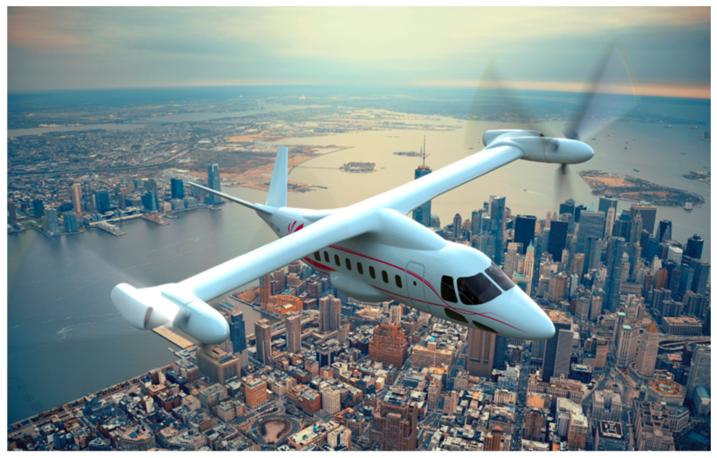
Figure 1 is a rendered view of the NGCTR-TD. The purpose of this study is to assess if the wingbox of the technology demonstrator is up-scalable to a larger class of tiltrotor. The scope of the NGCTR-TD Wing research project (T-WING project under H2020 Clean Sky 2 [
1,
2,
3]) is to design, manufacture, and qualify a new high lift, low drag optimized wing capable of improving downwash impingement in helicopter mode and of increasing the total fuel capacity of the NGCTR-TD under development by Leonardo Helicopters Division (LHD).
From a general point of view, the tiltrotor configuration is considered a step beyond the state of the art in terms of performance, design, architecture, and product supportability. This was recently confirmed by the US Government Accountability Office, which identified a tiltrotor vehicle as a vehicle for the future long-range assault aircraft (FLRAA) [
4]. The methodology developed in this paper allows a quick scale-up and preliminary validation of the tiltrotor wing structure starting from the Technology Demonstrator (TD) data. This approach is more efficient than the standard approach based on main component redesign once the main vehicle characteristics change (e.g., weight, chord, wingspan, etc.). The need to have such a tool is justified for tiltrotors as the configuration is relatively new for the aeronautical industry and its market. In the future years, down-scaled (i.e., aerial urban mobility vehicles) and up-scaled (i.e., civil and military) tiltrotors with respect to NGCTR-TD will be developed by the main airframers. The market prospects predict an increasing demand for disc-rotor technologies in the civil field [
5]: business flights, air medical, search and rescue applications, and others.
In NextGen, tiltrotor is expected to have a wider range of capabilities than today and support varying levels of total system performance. In terms of flight operational performance, a wider range of capabilities regarding cruise speed, cruise altitudes, climb and descent rates, noise, and emissions will exist. A key aspect of NGCTR is providing environmental protection that allows sustained aviation growth.
The tiltrotor wing is one of the most critical airframe subsystems of the entire aircraft due to several requirements, often contrasting each other, to be fulfilled [
6]. As a first step, the wing structure shall be sized in such a way as to avoid the typical aeroelastic instability that characterizes the tiltrotor, namely whirl flutter. Wing bending and torsional stiffness have a fundamental role in pitch-whirl stability; therefore, there is often a need to properly tailor the composite structure to meet the requirements while maintaining the structural weight to a minimum. Another specific concern of tiltrotors is the airframe mode placement: those modes involve significant movement of the hub center in the rotor disc plane directions (usually caused by local deformation of the rotor and nacelle supporting structure) and shall have their frequency outside of prescribed bands to avoid forced response oscillations. In addition, the lowest elastic airframe mode shall have a frequency not lower than a prescribed value to avoid coupling with aeromechanical modes. Finally, the wingbox architecture shall be capable of hosting fuel bladders, hydraulic systems, electrical systems, flight sensor routing, and interconnecting drive shafts by respecting redundancy and segregation requirements. Therefore, it is important to study and develop the wing in an integrated way by using low-fidelity models (in the early design stages) and high-fidelity models (in the more advanced stages) and methodologies. Most of these methodologies can also recur to optimization routines for replicating the wingbox structural design of the technological demonstrator model in the full-size scaled version by means of sizing a well-prescribed structural layout with an exact scaled-up external geometry.
Optimizing topologically a structure has proven to be an efficient tool in minimizing weight for several engineering fields, and its interest has exponentially grown in the past few years with the recent progress in aeronautical applications such as unmanned aerial systems (UAS) [
7,
8,
9].
The TD wingbox is characterized by a three-spar concept that guarantees proper segregation among the various systems hosted by the wing. The aft spar has a curved shape to maximize the available internal space for fuel, thus matching the aircraft’s range requirement. The wing design must be compatible with requirements concerning strength, stiffness, and structure weight and, at the same time, the need to have a highly integrated production concept. The wing must also meet certain crashworthiness requirements provided by LHD. A particularly critical need, the subject of the optimization study presented in this work, concerns the protection of any cabin occupants from equipment externally mounted (including the wing) in a crash situation. To alleviate the inertia loads due to the whole wing mounted on the fuselage, a frangible wing section has been incorporated to fail well before the full inertial load level is achieved. Nonetheless, the wing frangible section has to be strong enough to withstand nominal and off-nominal flight and ground load conditions. This means that after the wing’s outboard portion has broken, the cabin needs only to withstand the weight of the remaining portion of the wing, thus reducing the risk of fuselage crushing and serious consequences for passengers. All these stiffness requirements collide with the need to have a wing structure as light as possible to guarantee more payload or a longer range for the up-scaled future tiltrotor. All these requirements made the NGCTR-TD wing design very challenging. These challenging aspects highlighted the need to develop and use quick and easy-to-implement tools that employed methods, with a certain degree of fidelity and whose results allowed to gain confidence and paved the way for subsequent stages of design refinement. The intuition was to entrust the structural up-scaling to a multi-objective optimization (MOO) process, based on genetic algorithms (GA). Based on stochastic global search methods, GAs provide several potential solutions to a given problem and, through the utilization of probabilistic transition rules, simulate the mechanism of natural biological evolution by applying the principle of survival of the fittest to produce better and improved approximations to a solution. At each generation, a replacement set of individuals is created by selecting individuals according to their level of fitness in the problem domain and coupling them together using operators borrowed from natural genetics. This process leads to the evolution of populations of individuals that are better suited to their environment than their “parents”, just as in natural adaptation. The average performance of individuals in a population is expected to increase, and the process terminates when some criteria are satisfied, e.g., a certain number of generations, a mean deviation in the population, or when a particular point in the search space is encountered [
10].
The purpose of the current work is not only to achieve the stiffness objectives with the minimum structural weight of the wing but also to compare the goodness of the results obtained with those of other tiltrotor manufacturers in a real-world scenario. In this regard, a summary of the tiltrotor data is collected below. In general, unlike fixed-wing aircraft, there is insufficient data available on tiltrotor wing designs to establish a statistical database for wing weight prediction. Detailed preliminary research on the weights of the wings of existing tiltrotors or in the design or prototyping phase was carried out, considering references [
11,
12,
13,
14,
15,
16,
17,
18,
19,
20,
21,
22].
Table 1 summarizes the results of this state-of-the-art research, such as: the maximum take-off weight of the tiltrotor
W0, the structural weight of the wing
Ww, and the ratio between the two weights
Ww/
W0. It can be seen how the ratio between the two weights is kept almost constant among the tiltrotors considered. This value is included in a range from 6.1% to 7.3%.
The present work is divided as follows: (i) after an introductive part, a first section presents the TD wingbox and the scaling objectives; (ii) a second part introduces the scaling objectives and constraints; (iii–iv) the third and fourth parts introduce methodologies, tools, and the mathematical architecture of the proposed optimization scheme; (v) the fifth part is to be considered a demonstrative appendix on the instability due to buckling and how it is treated by the optimization tool; and (vi) finally, in the sixth part, results and lessons learned are provided.
2. Scalability Objectives: From Basic T-Wing Configuration to the Up-Scaled Wing Layout
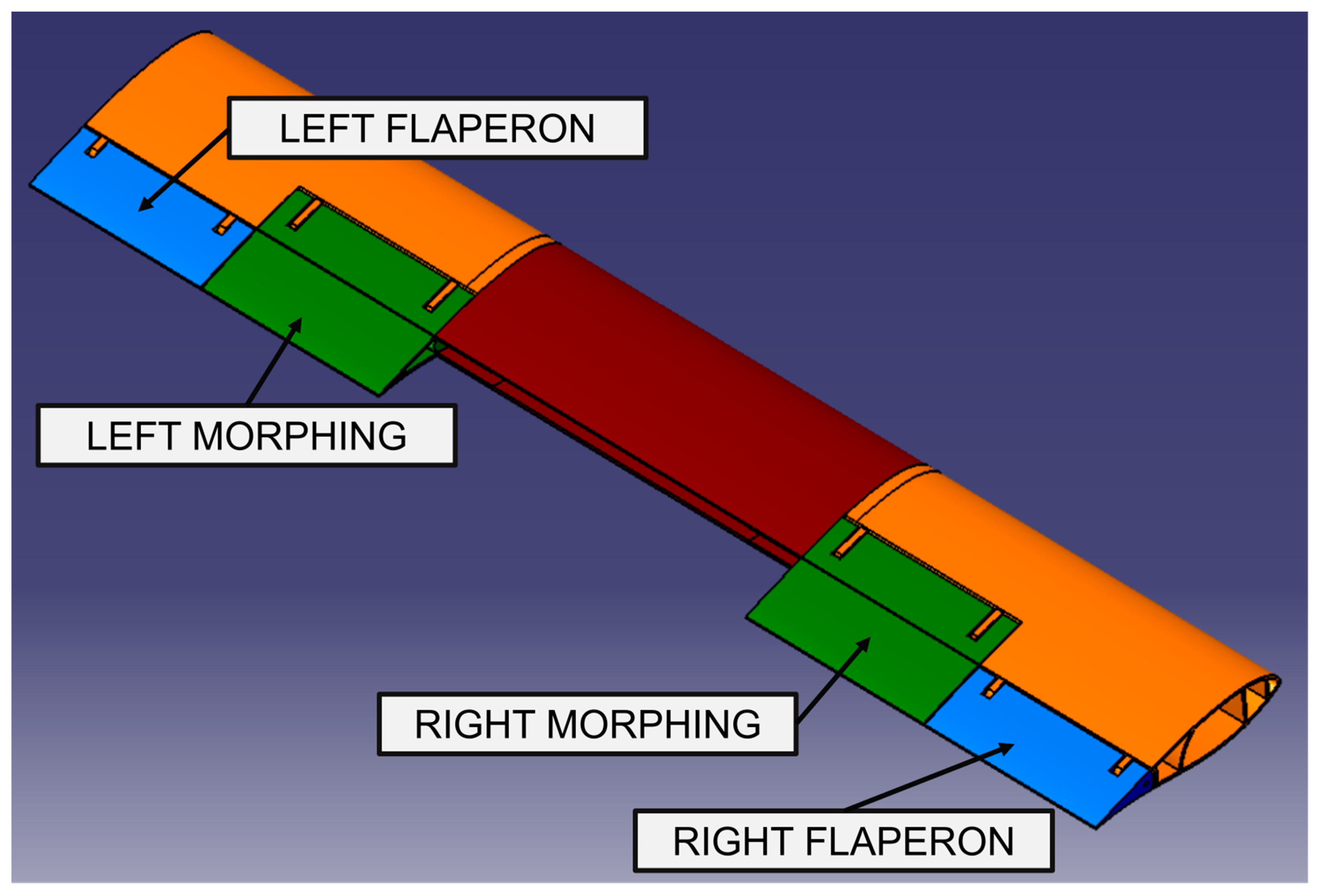
The wing design is very peculiar to tiltrotor aircraft. It features characteristics and constraints that are very different from conventional fixed-wing aircraft, and therefore it presents specific challenges. A key goal was to reduce the complexity of the wing by making it straight with no dihedral or sweep, thus providing easier assembly of the interconnecting shaft and eliminating the need for a mid-wing gearbox. In the TD wing, named T-Wing, downwash impingement is improved by the design of two movable surfaces: an outboard flaperon (blue in
Figure 2), about 28% of the total chord and about 32% of the semi-wingspan, which rotates downwards by 70° and upwards by 30°, and a morphing surface (green in
Figure 2), about 45% of the total chord and about 32% of the semi-wingspan, which can rotate upwards by 5° and downwards by 80° in helicopter mode to reduce the wing area beneath the proprotors. T-Wing is a multi-cell carbon composite torque box. The composite spars, front and middle, are located at 7% and 19.1% chord, respectively. A third curved spar (rear) is located at 45.8% chord.
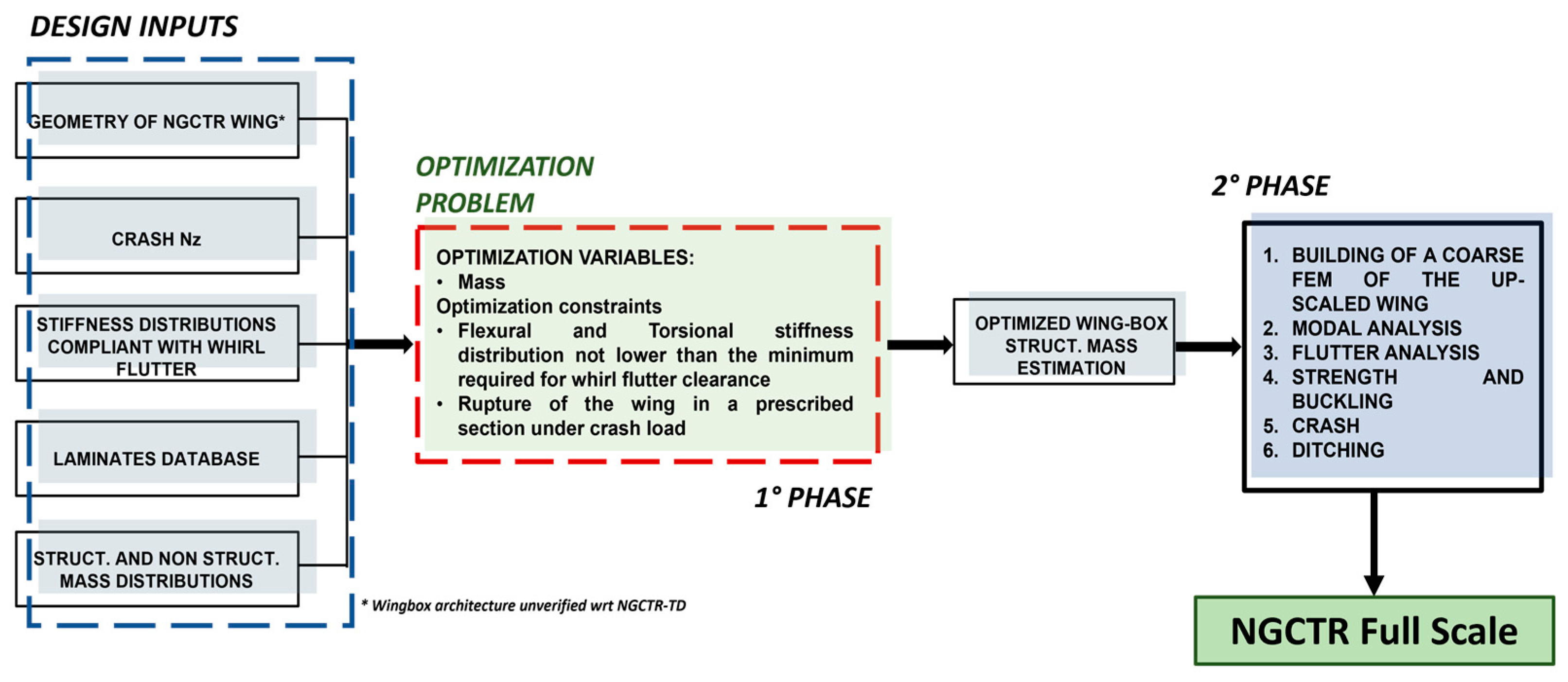
The scalability process is aimed at investigating the feasibility of adopting, for the up-scaled wing, the same structural criteria and technologies used for TD wingbox design. This activity has the aim of obtaining the best structural compromise, with an acceptable weight penalty, through the comparison of different composite materials (mechanical properties) and layups. The work shown in this paper is the 1st phase of the scalability process assessment, as shown in the dashed rectangle in
Figure 3. This 1st phase relies on quick tools based on engineering formulas to allow finding optimized solutions with minimum computational effort. At this step, the preliminary optimization problem is addressed: to identify the optimal solution that minimizes the structural weight and simultaneously satisfies stiffness requirements coming from whirl flutter clearance and crashworthiness. The crashworthiness requirement is imposed as a constraint, i.e., it is imposed as the failure of the structure around the frangible section, while maintaining a minimum margin of safety (MoS) elsewhere in the wing, under the vertical load factor experienced during such a crash event. The simplified choice of the optimization constraint of having a low MoS in the so-called frangible section and a higher MoS in the other locations was based on the preliminary information coming from linear static crash analyses [
23,
24]. Certainly, this is a low-fidelity approach that is meant to be the starting point of the subsequent phase of analysis, which will rely on higher-fidelity models and tools. The plan is to build, in the 2nd phase of the scalability studies, a global finite element model starting from the optimized sizing, which will be used to assess strength, buckling, flutter, crash, and ditching.
3. Multi-Objective Optimization Tool—Multicella and Methods
An in-house optimization environment named Multicella, originally aimed at performing preliminary calculations on composite wingbox structures for strength and buckling analysis purposes, has been implemented with a Multi-Objective GA optimization process.
Multicella is a MATLAB™ (ver. R2017b, MathWorks, Natick, MA, USA) code whose core solver is based on engineering formulas for thin-walled structures [
25]. As a result of the optimization tool, it was possible to preliminarily size the skins, spars, and stringers of the NGCTR-TD pre-defined wingbox architecture for minimum structural mass. These sizing results were used to build a first (global) wing FE model that was used at the preliminary design review (PDR) level, which—in turn—was then used to build a detailed FEM at the critical design review (CDR) level.
MOO finds optimal tradeoffs between competing objective functions. MOO involves minimizing or maximizing multiple objective functions subjected to a set of constraints. MOO is widely used in many fields, such as engineering (construction design, chemical process, manufacturing, engine design…), finance (risk return in portfolio management), and economics (consumer demand supply study, monetary policy, production possibilities frontier…). For the T-Wingbox structure, Multicella was used as the solver to allow the calculation of the different up-scaled wingbox architecture objectives to be optimized, thus feeding the MOO part of the analysis. More in detail, MOO output is a Pareto front, constituted by design points of non-dominated optimal solutions whose fitness was calculated by Multicella. On the Pareto front, a solution is a wingbox with its overall structural mass (to be minimized) and the MoS (with respect to strength, buckling, whirl flutter stiffness, and crash, to be maximized). This work is mainly focused on whirl flutter and crash problems; furthermore, par. 5 shows a brief demonstration of the Buckling Multicella solver. Some results are provided to correlate numerical aspects of the optimization with theoretical and engineering aspects.
The MO optimization phase is based on a GA due to its capabilities to explore a huge space constituted by a lot of design variables with numerous local maxima and minima. The Multicella solver receives the following as inputs: the wing planform, the airfoil shape, the shear, bending, torque, and tension loads along the wingspan, and a material database (density, elastic, and shear moduli of the lamina material, the composite stacking sequences for skin and stringers, the material strength allowable, and the critical buckling load). The tool is able to calculate, for a multiple-cell wingbox section, the following: internal normal and shear stresses and their corresponding MoS, buckling MoS, torsional and flexural stiffness (beam segments), and structural mass.
Regarding materials, for optimization purposes, five different materials were considered. In more detail, MAT01 and MAT05 are composite materials of the fabric type. MAT03 and MAT04 are unidirectional tape laminates, whereas MAT02 is a unidirectional tape plus impregnated woven fabric. The mechanical properties of each material used in the study are contained in
Table 2.
Concerning the material data, if the material is orthotropic (e.g., CFRP laminate), the properties are inputted to Multicella as laminate equivalent engineering properties (preliminary calculated by means of the classical lamination theory—once lamina level properties and lamination sequence are known, by using a dedicated spreadsheet named laminate.xls and introduced in the optimization input database).
The optimization was performed in two steps in order to better identify the most relevant contributions to the up-scaled wing mass.
Whirl flutter is a dynamic aeroelastic instability that may occur in a flexibly mounted engine and propeller system. The elastic modes of the system are coupled by the gyroscopic effects of the turning rotor disk, resulting in complex mode shapes of the mechanical system. The propeller vibration causes a change in the propeller blades’ angle of attack that will result in the generation of unsteady aerodynamic forces. Due to that, the vibrations could become unstable for aeroelastic mode interactions and could result in engine, nacelle, or whole wing failures [
26,
27,
28]. Therefore, the wing structure must have a stiffness distribution in order to avoid the onset of the whirl flutter phenomenon: the whirl flutter requirement is implemented in the optimization tool as a constraint on the wing stiffness values (flexural and torsional) as a result of a parametric whirl flutter analysis.
To define the crashworthiness requirement for the NGCTR wing, the first step was to identify the desired frangible section.
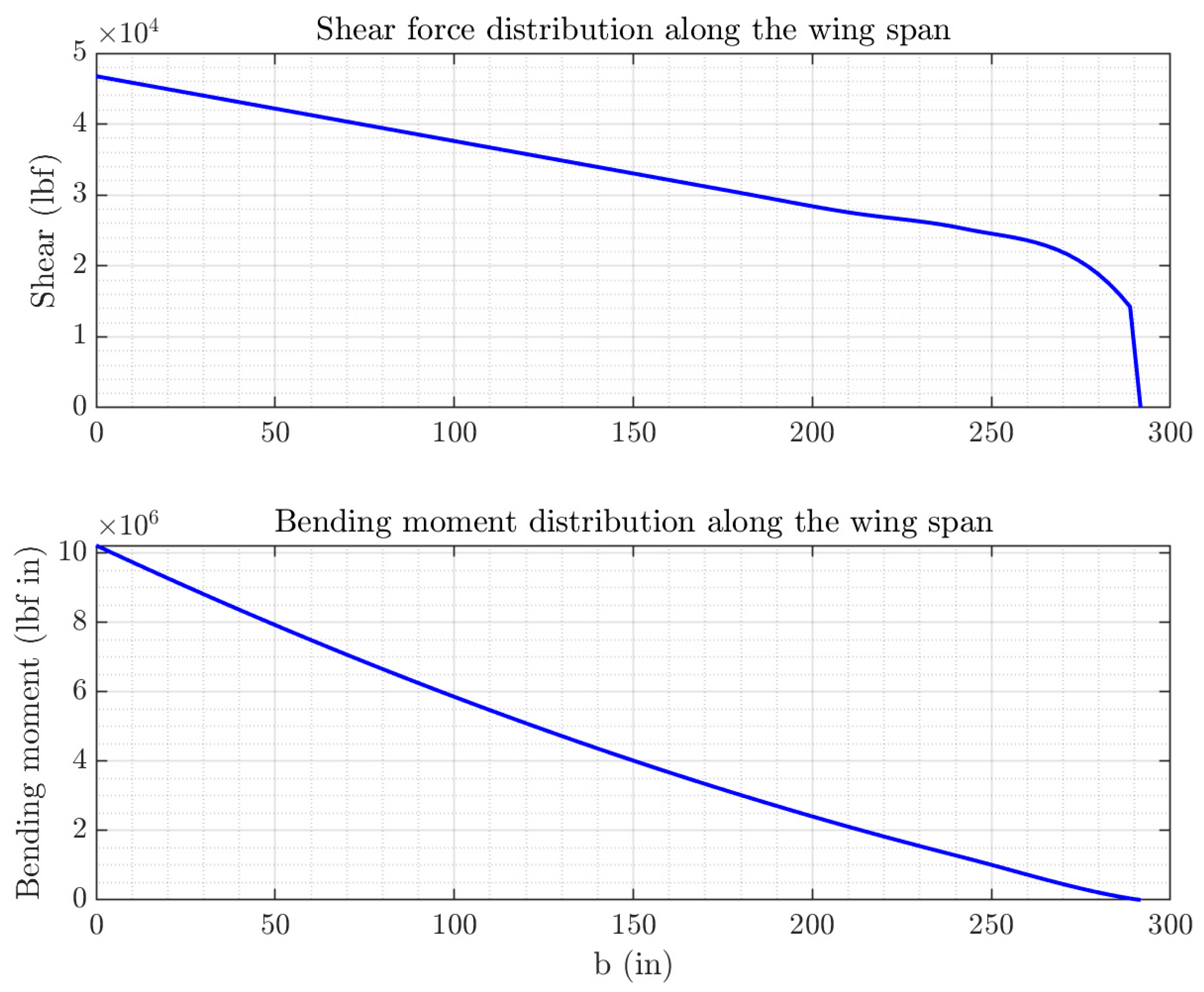
A MATLAB® tool has been developed that, starting from the distribution of the masses, calculates the load acting along the wing during the crash load condition factor (nz = 5 high-level design requirement) by integrating the inertia forces and providing the shear and bending moment diagrams.
For the calculation of the inertia forces on the wing, the mass of the entire structure is considered (wingbox, movable surfaces, fuel, and systems). The MATLAB
® function outputs forces and moments (
Fx,
Fy,
Fz,
Mx,
My, and
Mz). Starting with the mass distributions of the LHD’s FEM dynamic model, the distributions of shear force and bending moment along the wingspan are obtained, as shown in
Figure 4.
The crashworthiness requirements are implemented in the optimization process to have the minimum, near-to-zero, MoS at the wing frangible section and a low, positive MoS elsewhere in the wing. This constraint ensures that, for given design loads, the material offers minimum strength in the frangible section.
In order to also consider the stiffness requirements, a penalty (minus 1) on the MoS is added for solutions that do not respect the torsional stiffness requirements.
The results of the optimization are Pareto fronts showing the wingbox solutions compatible with these optimization constraints.
4. Mathematical Architecture of Multicella Tool
In the following, the mathematical architecture of the proposed process and the presented optimization scheme have been clarified.
In the case of several objective functions to be simultaneously optimized, optimization solvers find the optimal tradeoffs between the competing objective functions.
The wingbox structure can be considered a compound engineering system whose design has many objectives to be minimized or maximized, and this leads to a MOO problem. MOO Multicella, based on a GA and written in MATLAB® language, has been used to optimize the wingbox structure. This robust and efficient tool provides a set of optimal solutions for a MOO problem since the final decision is always a trade-off.
Optimization objectives are the wing structural mass (to be minimized) and the strength and buckling MoS (to be maximized). Additionally, the points on the Pareto front are labeled with the wingbox torsional stiffness and the wingbox first bending normal mode (calculated off-line, at the end of the optimization phase) to restrict feasible solutions to comply with other design requirements. As optimization variables, the thicknesses and areas of the different structural parts (wingbox panels and stringers) of the wingbox are chosen.
The following input data are needed by the program:
Semi-wing plan form;
aerofoil shape;
caps chord-wise length (that multiplied by thickness gives their areas);
load beam characteristics (shear, tension, bending, and torque, i.e., Fx, Fy, Fz, Mx, My, and Mz at each section where the stress has to be evaluated) at representative buttock lines of the wing span;
material database that is used for structural elements in the section (caps and panels modeling spars and skins). The database is composed of:
density, elastic, and shear moduli of the lamina material;
the composite stacking sequences for skin and stringers;
the composite material strength characteristics (tensile, compressive, and shear allowables) and buckling loads.
wing buttock lines at which the output has to be calculated.
The optimization tool is able to calculate, for a multiple-cell wingbox section, the following quantities:
Internal normal and shear stresses and corresponding MoS;
buckling MoS;
torsional and flexural stiffness;
total and span-wise structural mass estimation, with also a subdivision among the structural components (skin, spar, stringer, and webs).
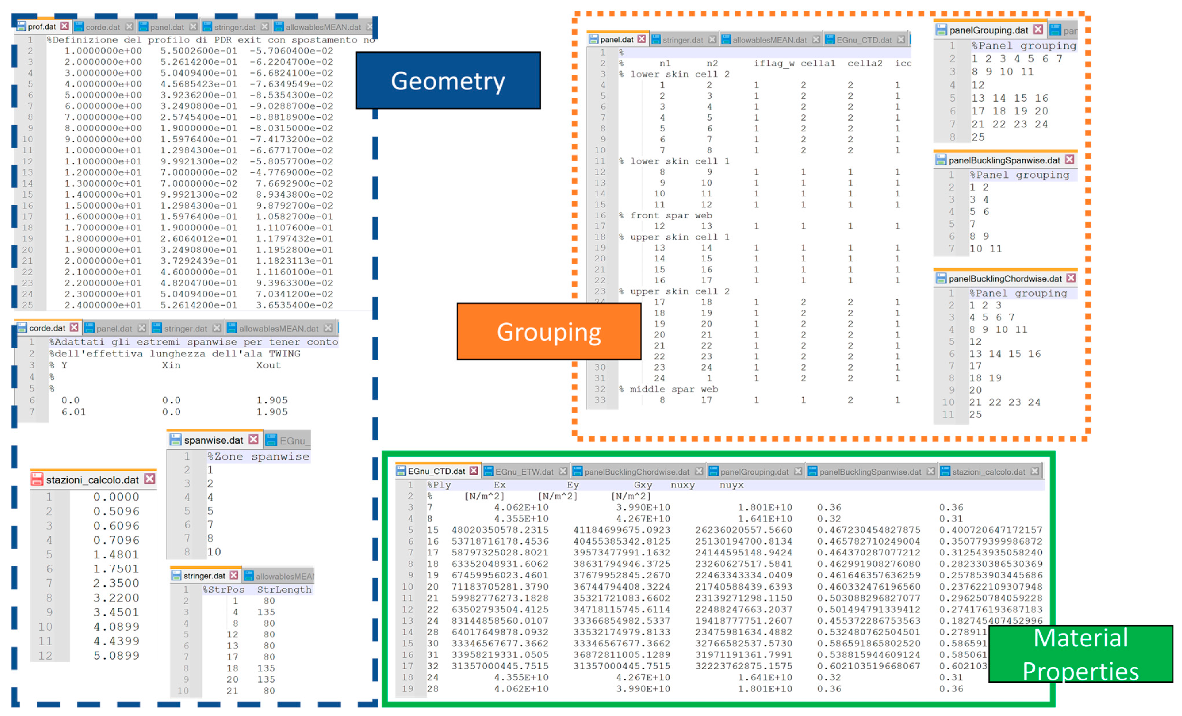
Figure 5 shows an overview of the input files containing parameters implemented in Multicella for a generic case study in order to provide a reference and setting support for all parameters used.
Multi-Objective Optimization Tool Technical Description
Figure 6 illustrates the block diagram of the Multicella code operational flow and the architecture of the optimization tool, whose description is extensively discussed below. The structural analysis and optimization process can be divided into different phases. At each step, a dedicated set of files is used. The various phases can be summarized as follows:
Wingbox geometry is expressed through a series of input files. These files are captured by the main MATLAB® code before the optimization of skin thickness and cap areas is started.
The input files defining wing geometry are:
It contains information on the geometry of the wing profile in terms of normalized point coordinates with respect to the chord, in a suitable reference system. The origin of the reference system is placed on the leading edge. The x-axis is along the wing cross-section chord and directed from the leading edge to the trailing edge; the vertical z-axis is directed upwards.
It identifies the connections between the points of prof.dat making up the profile; in such a manner, the front spar, the middle spar, the rear spar, the lower skin, and the upper skin of the section are defined.
This file contains the variation of the chord along the wingspan (y-axis), starting from the root and moving towards the tip of the wing.
This file indicates the points of prof.dat where the stringers are positioned and their corresponding lengths.
The second step consists of dividing the wing into structural groups whose thicknesses will be optimized.
The files containing the grouping information are divided into grouping for strength analysis and grouping for buckling analysis.
This file contains the sections along the wingspan where the tension and shear stresses will be calculated. This file subdivides skin and stringers spanwise. Generally, ribs and other “discontinuities” because of movable surfaces define the spanwise segmentation.
Each line of this file corresponds to a group of panels contained in panel.dat that define a part of the skin whose thickness is intended to be optimized as a whole.
It contains the identification of the sections (along the wing) and defines the segments for the buckling analysis.
- 2.
Grouping for buckling analysis:
For wing skin supported by stiffeners, the buckling can be considered to arise in panels delimited by the stringers and the ribs of the wingbox; two files provide the panels to be analyzed for buckling purposes, respectively along the chord and the wingspan:
- ○
panelBucklingChordwise.dat is similar to panelGrouping.dat. It groups panels contained in panel.dat to identify panels for buckling analysis;
- ○
panelBucklingSpanwise.dat basically identifies the wing sections where ribs are present.
This file contains the homogenized values of the mechanical properties (elastic modulus along both directions, shear modulus, and Poisson’s ratio) for several laminates that can be used for wing panels and caps (different thicknesses and different fiber orientations and layups). Lamina mechanical properties can be introduced for various temperature conditions.
It consists of an array containing, for various wing stations, the six beam load components Fx, Fy, Fz, Mx, My, and Mz (forces and moments with respect to the three axes of the cross-section: x-axis from the leading to the trailing edge, y-axis spanwise from root to tip, and z-axis upwards). This file is generated from the load conditions provided by LHD (shear, bending, torsion, etc.).
Buckling is the failure of a structural element when a portion of the element moves normally to the direction of the primary load application. The deformation alters the mechanism by which loads are transmitted. It is the combined loading of compression and shear stress components that forces the buckle to occur. When the skin is not thick, the buckling stress of the skin may be comparable to the yield stress of the material.
Calling “q” the angle obtained from the composition of compression and shear loads, two extreme cases emerge:
- ▪
q = 0 when a compressive force alone is applied to the panel;
- ▪
q = 90° when a shear force alone is applied to the panel;
- ▪
0 < q < 90° for combined load conditions.
For a fixed q angle, the compression and shear forces are defined by a certain gain between them. The buckling limit loads are calculated offline for the laminates that will be used in the optimization process and are thus stored in a MATLAB®® file:
- ○
BucklingPreProWing.mat. This file is a 5D multidimensional matrix. It contains buckling loads for:
the two dimensions of the panels tested at Buckling in the optimization process (derived from panelBucklingChordwise.dat and panelBucklingSpanwise.dat files);
the angle q: from 0° to 90°with a step of 1° deg;
the lay-ups database used for panels (expressed as the number of plies of laminates database);
the load conditions are cold temperature dry (CTD) or elevated temperature wet (ETW).
For each panel under investigation, the critical buckling load is calculated by means of the Rayleigh–Ritz method based on the plate’s potential energy, as reported in §6.
5. Up-Scaled Wing Multi-Objective Optimization and Results
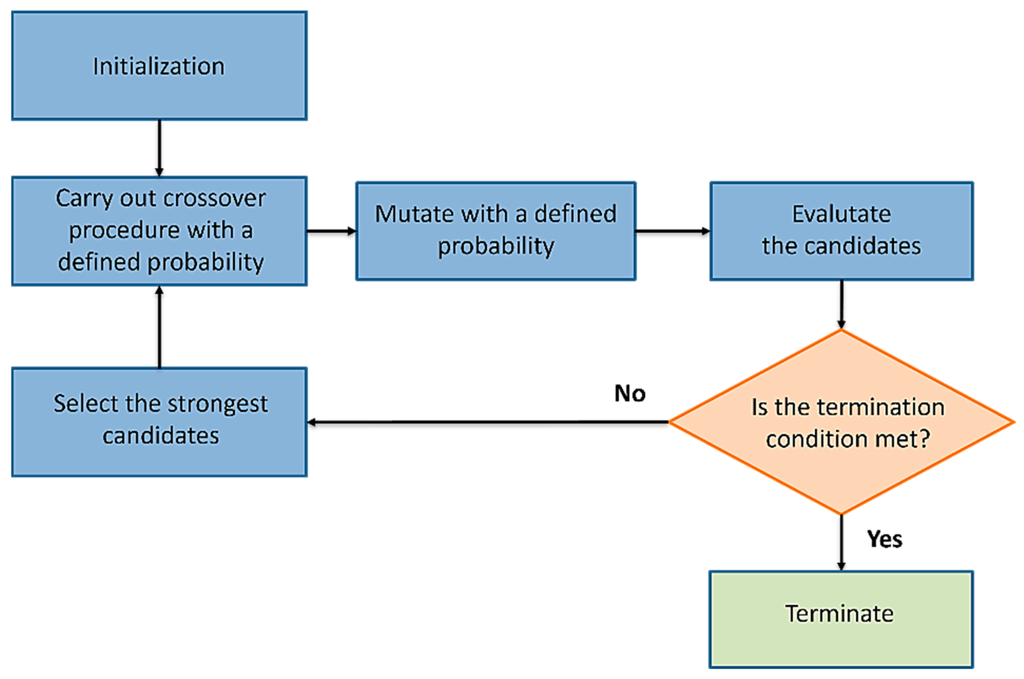
The GA has the significant advantage of searching a population of points in parallel, not a single point, making the optimization process very fast. The T-Wing preliminary design and the structural scalability process are MOO problems; thus, there is not one single solution but a family of Pareto-optimal solutions. The GA is potentially useful for identifying these alternative solutions simultaneously; however, the choice of an ultimate better solution is left to the user. The general form of GAs is presented in
Figure 7.
The first step of the GA is initialization [
29]. This generates, often randomly, a population from which new generations are formed. At this point, it needs to define the terminating condition too, so that the algorithm stops running once an acceptable solution is found [
30]. The second step is the crossover. Crossover is one of the genetic operators used in producing new candidates using the features of the existing ones. The crossover procedure consists of three parts. The first one selects two parents from the population. Then the crossover points are selected. The selection of crossover points is performed randomly, so that the distribution from which the points are drawn is uniform [
31,
32]. Once the points are defined, two offsprings are generated by interchanging the values between the two parents. In the GA crossover, the operator spreads the advantageous characteristics of the members around the population. Focusing on the third step in the GA, mutation is the operator that causes totally new characteristics to appear in the members of the population. In many cases, the mutations, of course, result in offspring that are worse than the other members, but sometimes the result has such characteristics that make it better. Firstly, the mutation operation selects a member from the population to be mutated and a point of mutation. Then, the values at the point of mutation are replaced by another value that is picked randomly from the set of all possible values. After the population is manipulated using the genetic operators, the fitness of each of the new offspring is evaluated. For this one, it needs to have a fitness function to be evaluated. In the selection, the weakest individuals in the population are eliminated. The fit offsprings survive to the next generation.
The present section is devoted to the assessment of the scalability of the NGCTR-TD composite wingbox up to the larger class “NGCTR” (MTOW = 30,865 lb) by considering the most relevant requirements that had a big impact on the TD wing sizing, namely whirl flutter and crashworthiness requirements.
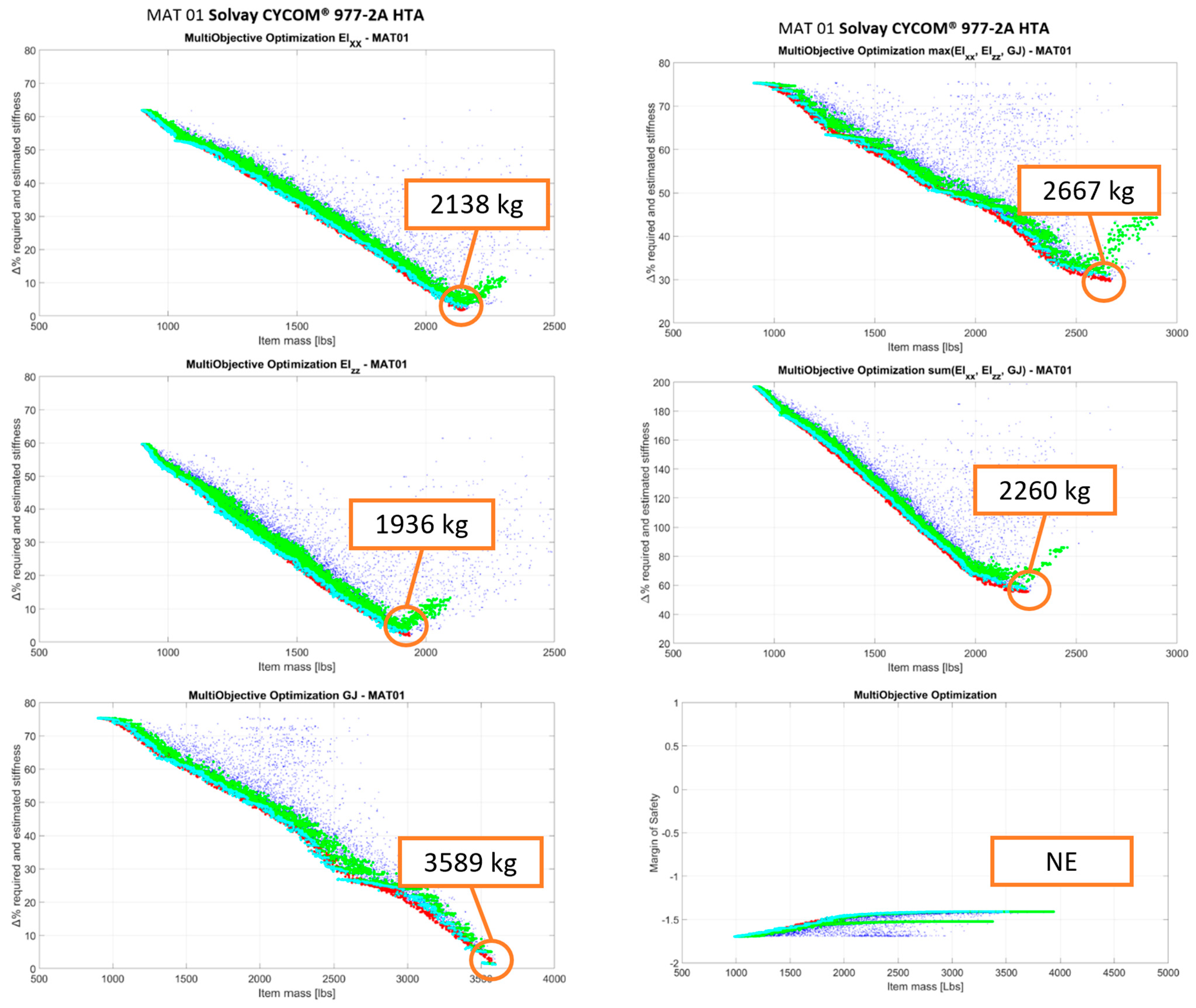
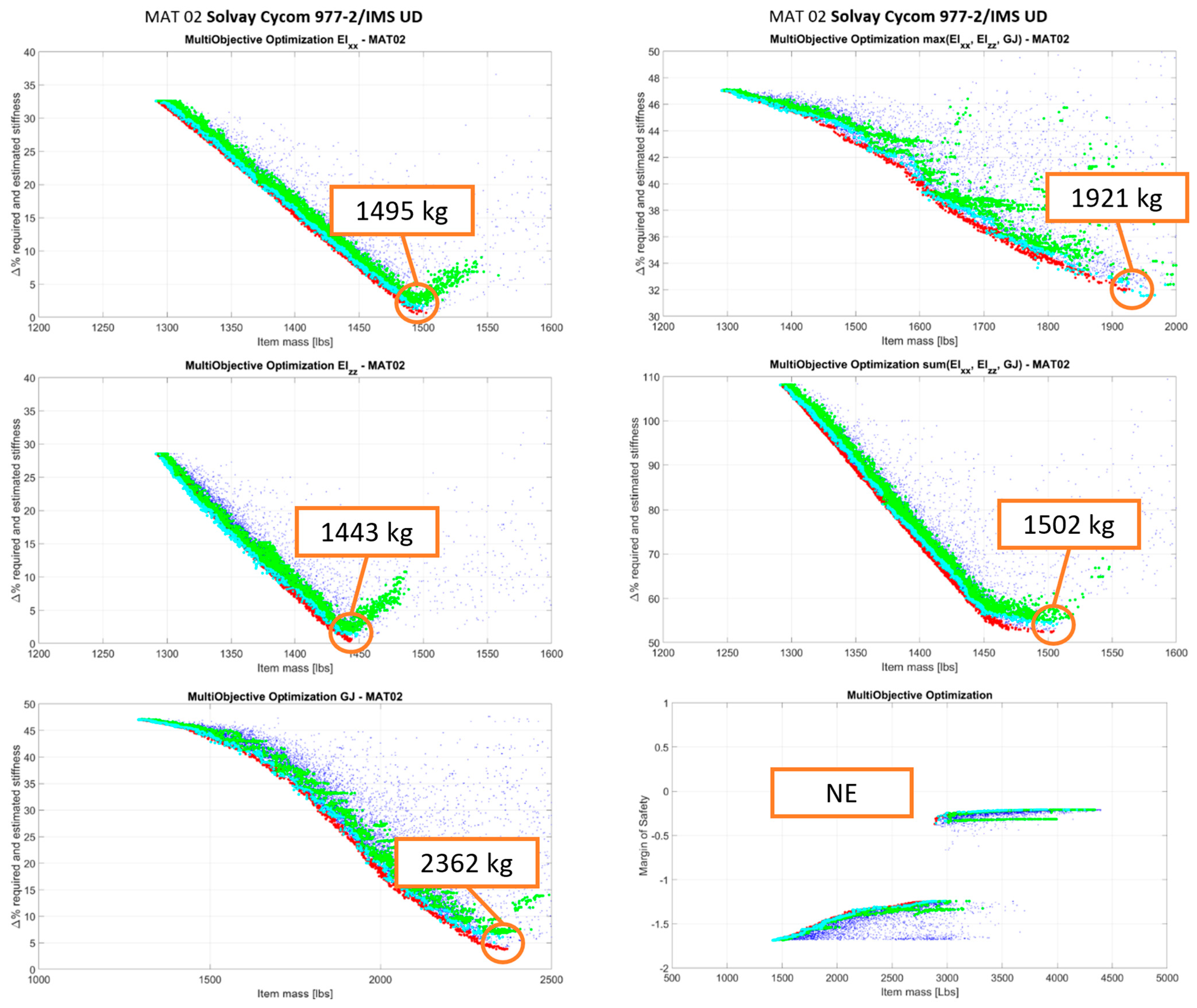
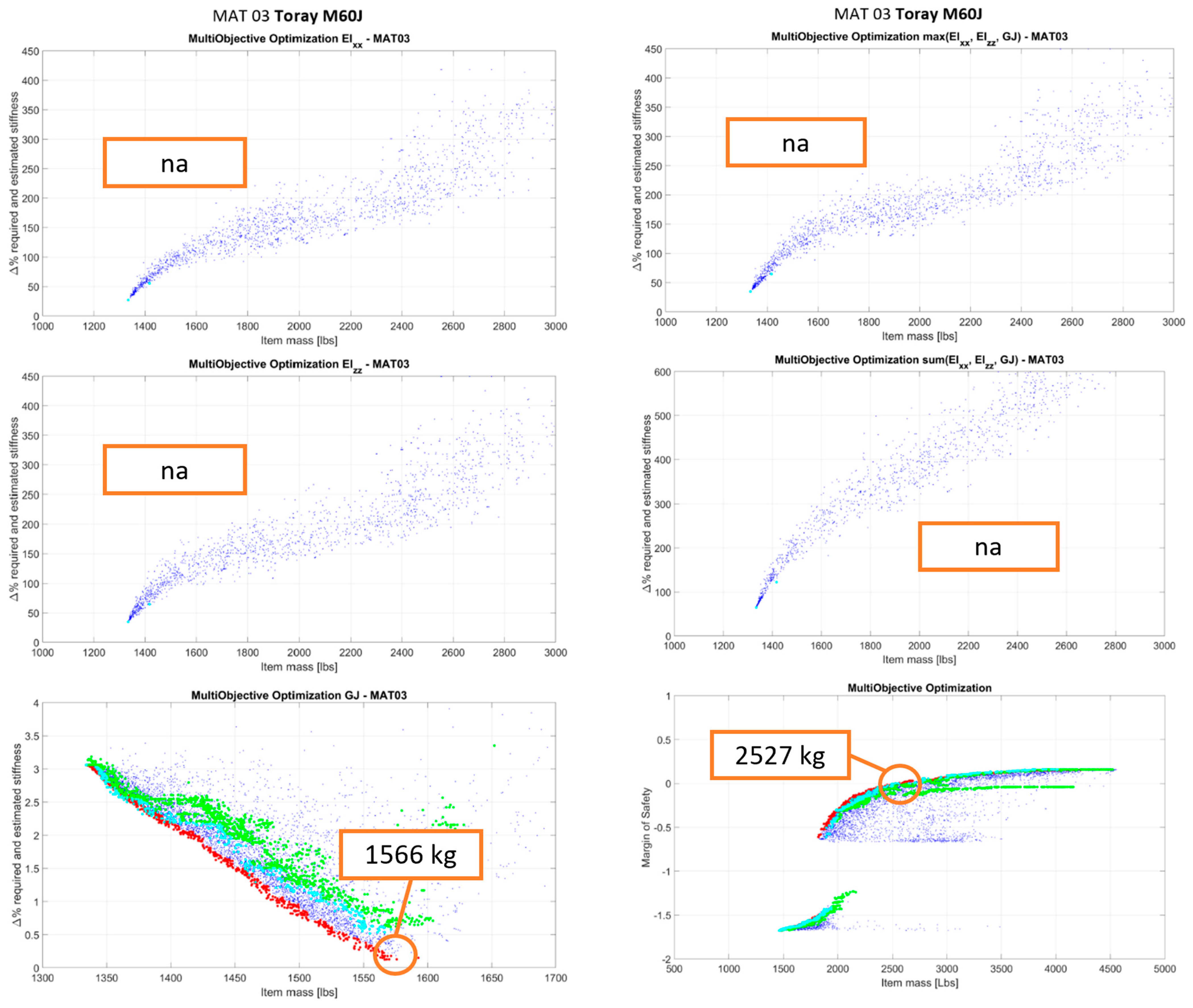
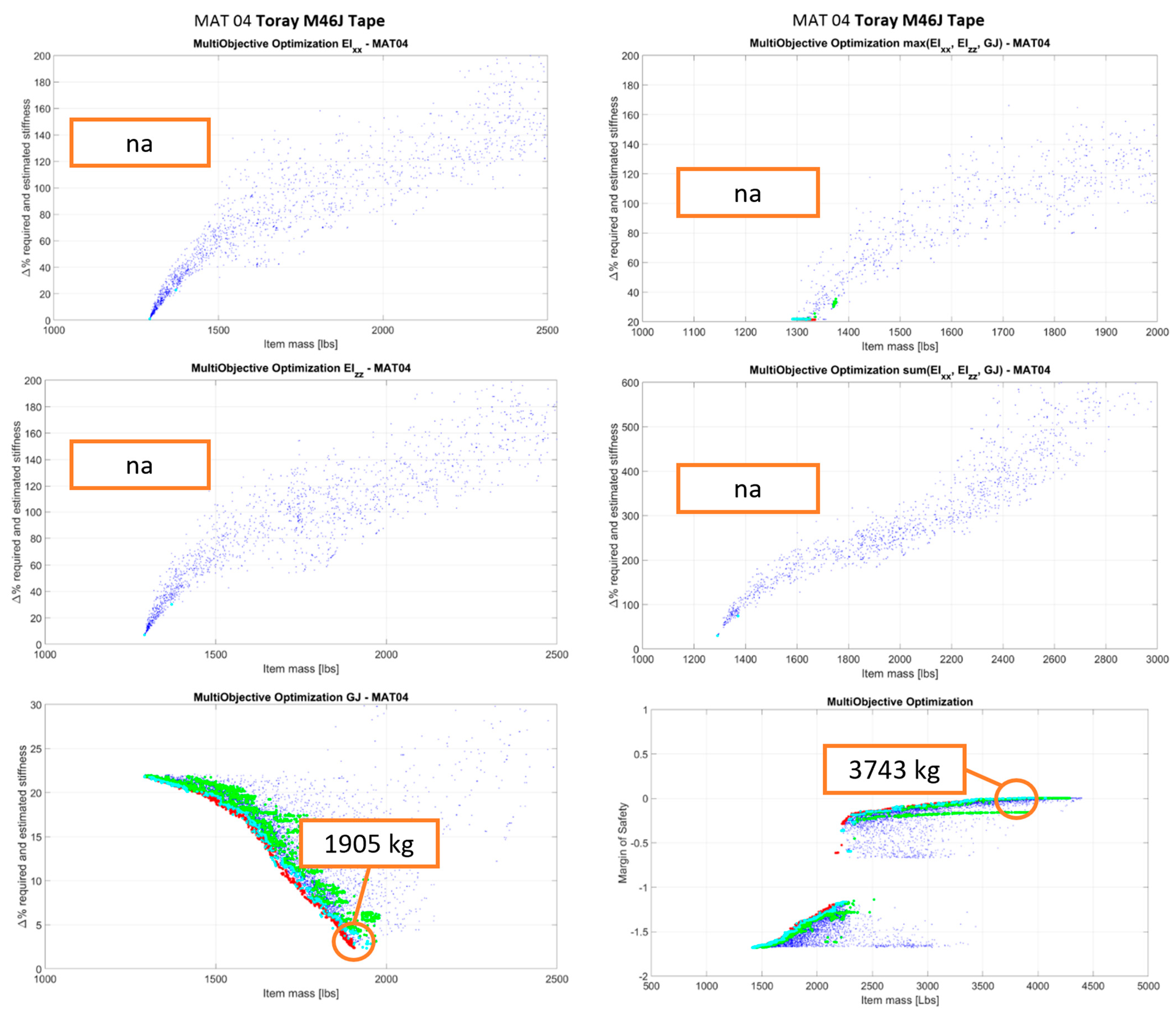
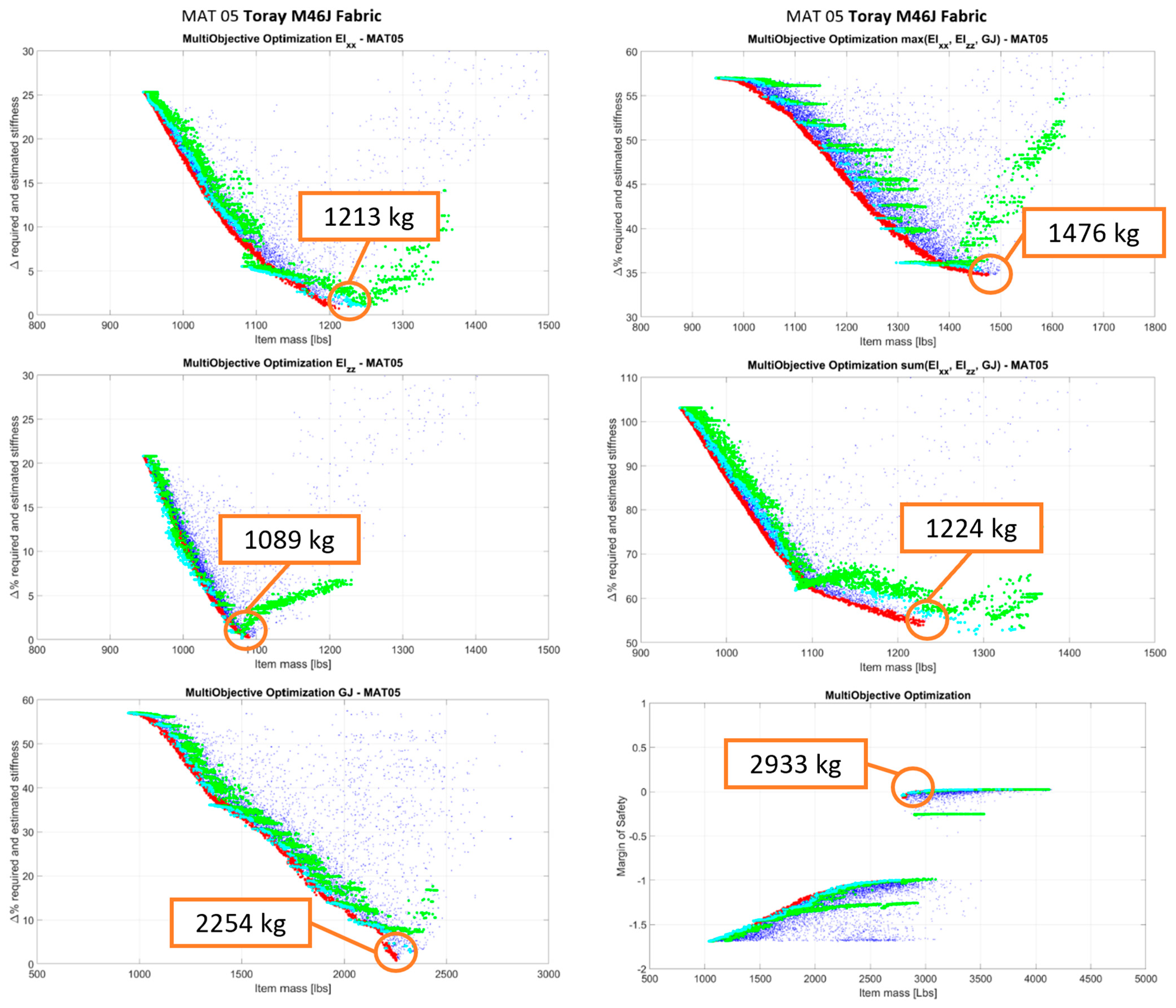
The results are provided as Pareto fronts. Pareto front is a set of points that verifies the property that each one of these points is not dominated by another one (no point exists that has better properties on all the optimization objectives).
On the Pareto fronts depicted in
Figure 8,
Figure 9,
Figure 10,
Figure 11 and
Figure 12, the blue points represent all the points analyzed by the optimization algorithm under the assumption of composite layups, with continuous thickness variability. The red points are definitely Pareto points. The green points are derived from the red points and represent feasible optimization solutions (solutions compliant with layups with discrete thicknesses). The cyan points are a subset of the green points (best among them). For each material, optimizations have been performed with respect to:
- ○
Flexural stiffness ΔEIxx [%];
- ○
fore and aft stiffness ΔEIzz [%];
- ○
torsional stiffness ΔGJ [%];
- ○
the maximum of (ΔEIxx [%], ΔEIzz [%], ΔGJ [%]);
- ○
the sum of (ΔEIxx [%], ΔEIzz [%], ΔGJ [%]);
- ○
ΔGJ [%] and crashworthiness.
The performed MOO was aimed at minimizing the structure weight and at minimizing the absolute differences between the structural stiffness of the solution under consideration and the corresponding required stiffness to comply with whirl flutter and frangible section requirements. For a given solution, for
Figure 8,
Figure 9,
Figure 10,
Figure 11 and
Figure 12, the y-axis reports values representing the minimum of the absolute stiffness differences along the wingspan.
The crash optimization was performed by taking into consideration the crashworthiness constraint and verifying that the solutions fulfill the stiffness requirement as well. As said before, the constraint of the crash optimization problem is that under crash loads, the wing fails around the frangible section, while maintaining a minimum MoS elsewhere in the wing. In this case, on the y-axis, a safety margin is reported that represents the minimum difference between the solution MoS and the one required along the wingspan. It is possible to note that the Pareto fronts of the crash optimization generally present two clouds/branches of data (an upper branch and a lower branch) due to the penalty applied to solutions that do not fulfill the whirl flutter requirement (the lower branch is composed of the ensemble of points that do not respect the whirl flutter requirements). The Pareto fronts reported in this paper are those related to the optimization of the up-scaled wing with respect to both stiffness and crashworthiness requirements. The optimization process, with the same crash and whirl flutter requirements, was also repeated for the tech demonstrator’s T-Wingbox: graphs relating to this analysis are not shown, but only the final weight of the selected optimal solution is reported in order to allow, in paragraph 6, a comparison between geometric scaling and weights.
In
Table 3, a summary of the optimized results is reported in terms of the structural mass of the up-scaled wingbox. The crash data have to be read as “wing optimized with respect to whirl flutter stiffness requirement plus crash”. Where the value reported is “na”, it means that there is room for optimization below the laminate minimum thickness and the minimum laminate thicknesses of the considered database satisfy the requirement under consideration. Where a value equal to “NE” for crash is reported, it means that an optimized solution that is compliant with both whirl flutter and crash cannot be found for that particular material and the layups of the composite database.
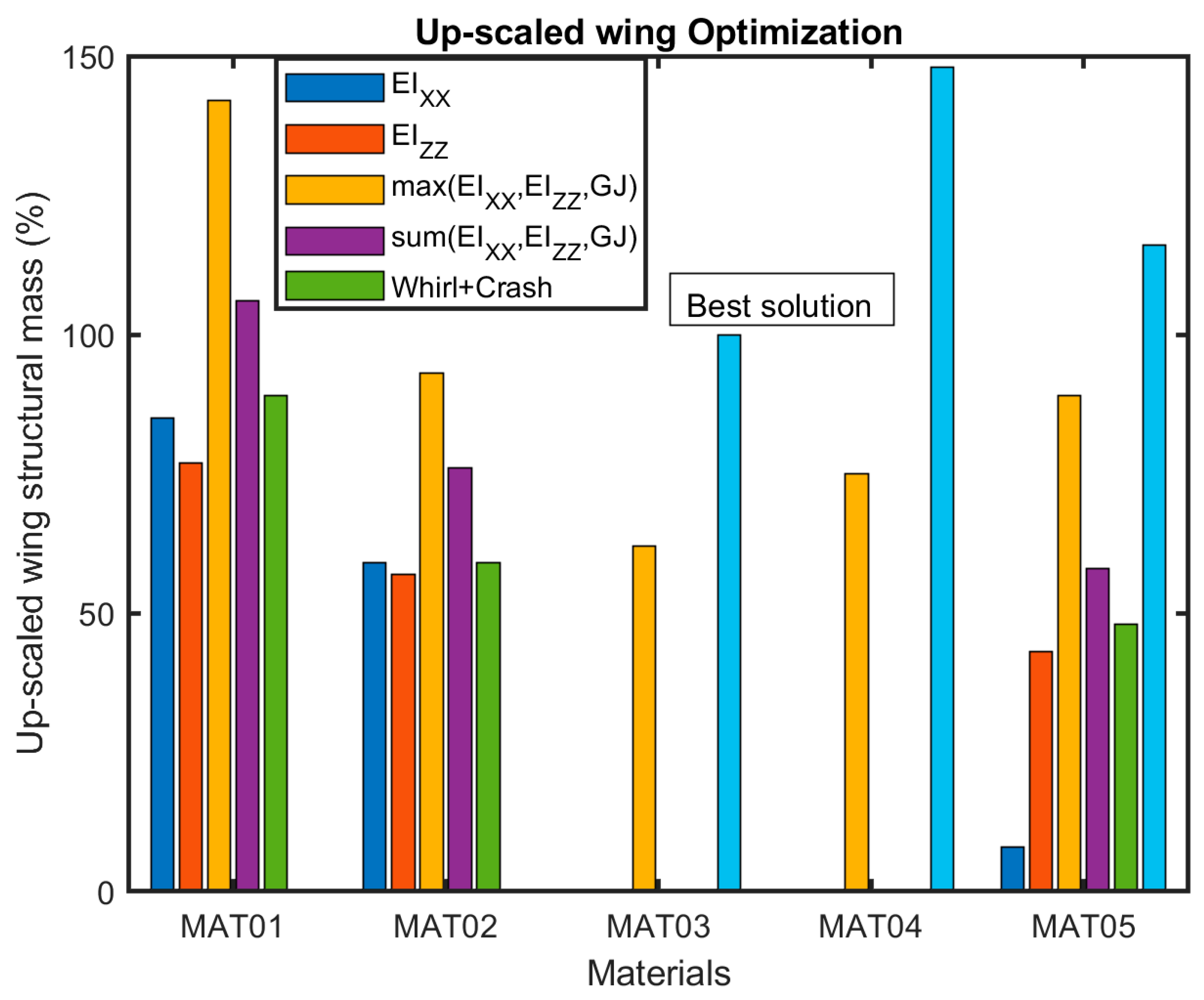
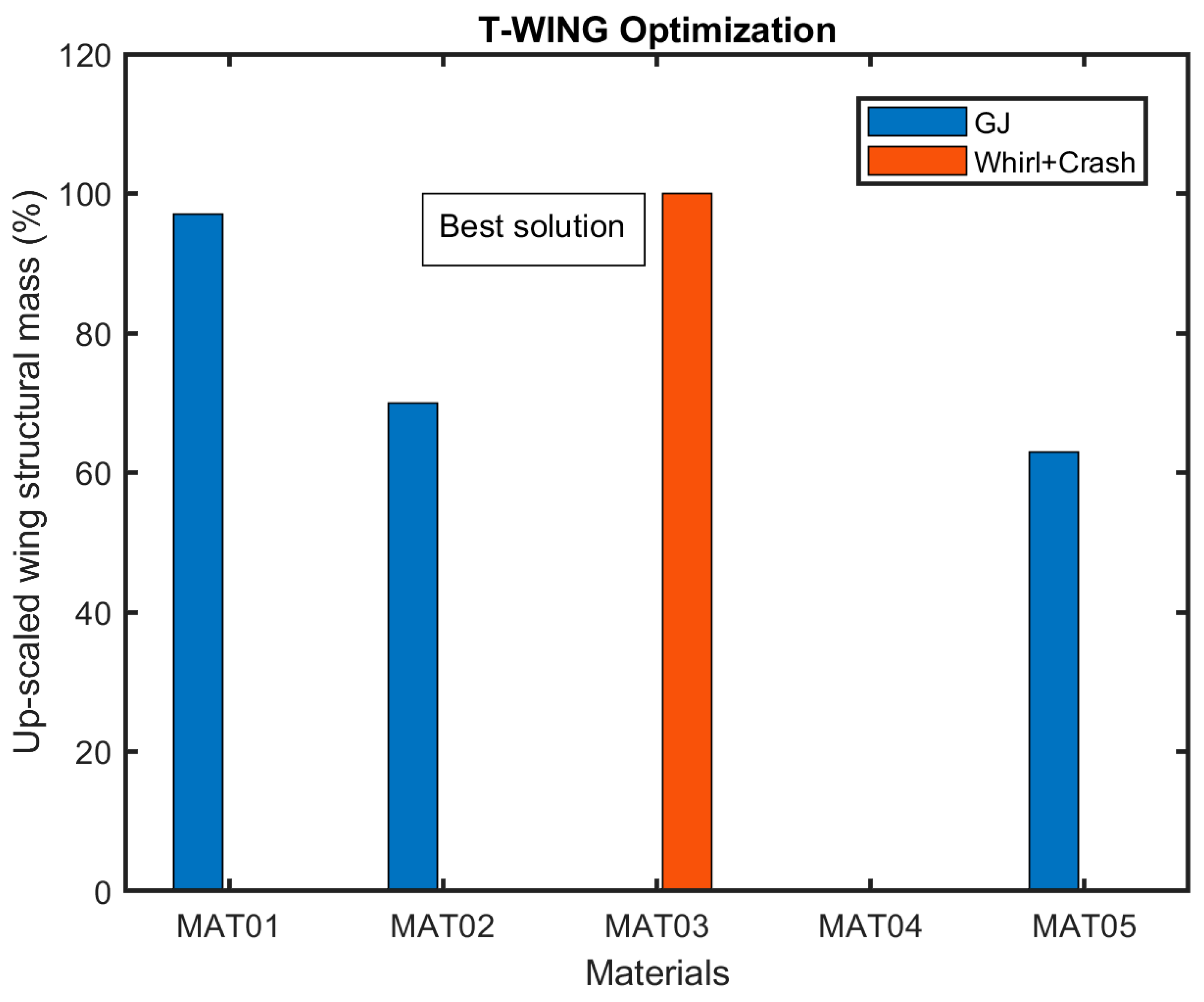
In the histogram of
Figure 13, the up-scaled optimized wing mass is reported with respect to each optimization performed. Red, blue, grey, yellow, and dark blue bars are the optimized solutions with respect to each stiffness (grey is with respect to torsional stiffness, the most demanding one). The green bar is the optimized solution with respect to whirl flutter (torsional stiffness) and crash. The following considerations can be drawn for the upscaled wing:
- ○
Optimization using the max or sum norm does not allow to obtain a solution with the minimum possible weight (suboptimal results obtained) due to the trade-off of the optimizer to reduce contemporarily all the stiffness differences concerning the targets.
- ○
By optimizing the wing concerning whirl flutter, the leading stiffness is the torsional stiffness (grey color in the histogram); this is fully in accordance with respect to the NGCTR-TD wing design heritage.
- ○
Crashworthiness requirements have a non-negligible impact on the weight; this is also in accordance with the T-Wing design heritage. This is due to the large masses at the wing tip, which cause high loads to develop on the wing under the crash vertical load factor. MAT01 and MAT02 are not able to fulfill both whirl flutter and crashworthiness requirements.
- ○
The maximum weight saving that fulfills both whirl flutter and crashworthiness is reached with MAT 03 Toray M60J; the other materials have solutions that are heavier with respect to MAT 03.
The results are reported in percentage terms in
Figure 14 to better appreciate the difference between each solution with respect to the optimal one.
Below is the information on the geometry of the wingbox of the upscaled wing derived from the optimization study, leaving some fundamental considerations for the final paragraph. The up-scaled wing has a chord of 96.7 inches (2456 mm) and is divided into two half wings, linked by an upper splice fitting, each one has a span of 289.8 inches (7360 mm). The NGCTR wing has two movable surfaces: an outboard flaperon, about 28% (27.1 inches—687.6 mm) of total chord and 83.98 inches (2113 mm) span, and a morphing surface, about 45% (43.5 inches—1105 mm) of total chord and 86.26 inches (2191 mm) span. The airfoil of the NGCTR Wing is the same as the T-Wing airfoil, as well as the percentage of wingspan and chord occupied by the moveable surfaces and the number of ribs along the wing. The first rib is located 30.9 inches from the wing–fuselage attachment. The tip rib is positioned at 258.3 inches from the wing–fuselage attachment. Rib spacing is listed in
Table 4. The number of wingbox stringers considered to be the best choice based on the present study is equal to 9.
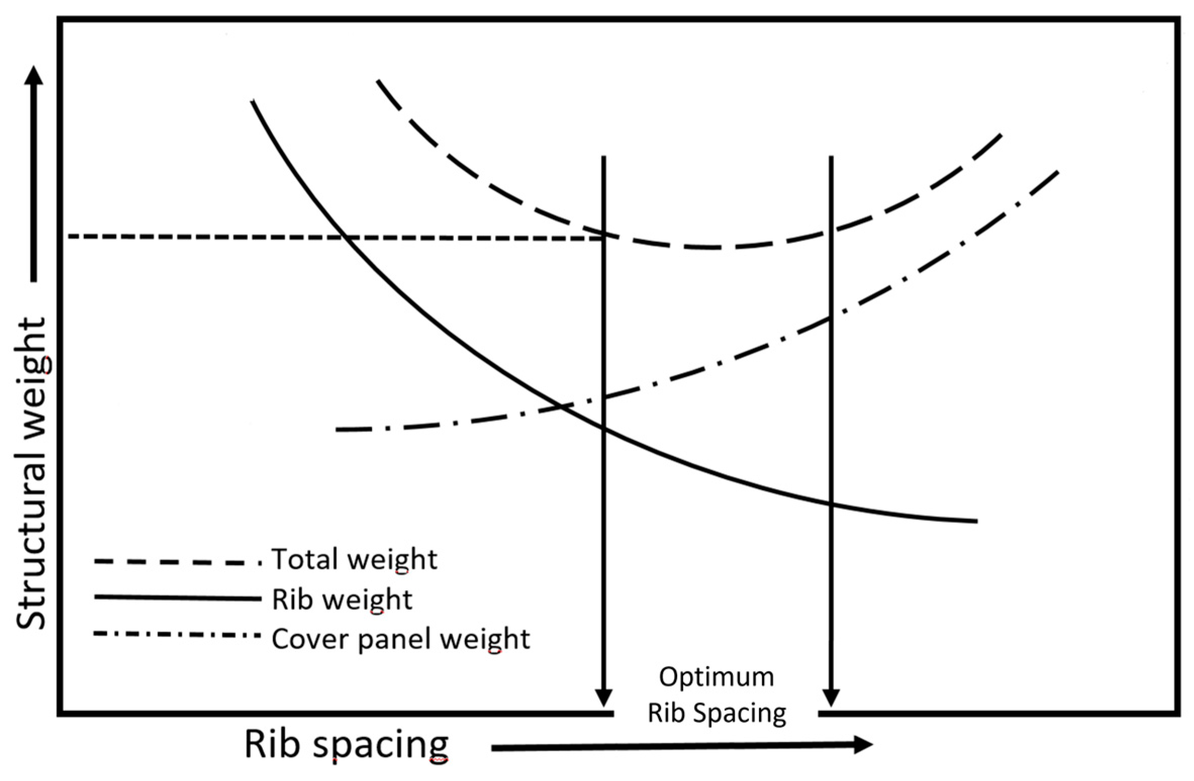
A final consideration concerns the ribs of the wingbox. Ribs are used to hold the cover panel in a contour shape and to limit the length of skin-stringer panels to an efficient column compressive strength. Ribs are likely to be located at each morphing and flap hinge. The rib spacing is determined by panel-size considerations, to which reference should be made. Some adjustments in the rib spacing may be desirable to get the hinge rib locations to coincide with the rib stations. With a view on preliminary structural optimization, since the weight of the ribs is a significant amount of the total wingbox structure, it is important to include the ribs in the overall optimization consideration of the structure. This is illustrated in
Figure 15 [
33], where the relative weight of the ribs and cover panels refers to the spanwise. For this graph, all design criteria (mostly concerning buckling) for covers and ribs are satisfied. It is advantageous to select a larger rib spacing. Once the primary wing structure has been defined, based on a set of load conditions, stress analysis and optimization are started to define the distribution of the thickness of the covers along the wingspan. About the wing covers, the wing bending loads that cause compression at the upper surface of the wing are generally higher than those causing compression at the lower surface. This requires that the stiffening elements along the upper surface be more efficient and also more closely spaced than those on the lower surface.
The torsional moments are primarily resisted by the skin and the front and rear spars. The air loads act on the wing panels, which transmit them to the ribs. The latter transfer them as shear loads to the main spar structures, distributing the load in proportion to the stiffnesses of the webs. The use of multi-spar allows a reduction in rib stresses and better support for the spanwise bending material. Furthermore, by considering a generic panel (a × b dimensions), as the panel aspect ratio (a/b) increases due to the increase in spar number in the cross-section, the critical buckling load of the covers gets higher. Hence, the covers can be designed with less thickness, resulting in mass savings [
34,
35,
36]. Additionally, the thickness of the ribs cannot go below a certain limit due to manufacturing constraints.
Among the various optimization process inputs, there is also the rib spacing defined based on preliminary calculation runs in such a way as to remain within the range for which the overall weight of the wing structure does not increase (“optimum rib spacing” interval in
Figure 15). The rib spacing is contained in
Table 4 in terms of wingspan percentage.
6. Buckling Optimization Analysis Results
The Rayleigh–Ritz method, based on the plate’s potential energy, has been implemented in the optimization process to determine the critical buckling load [
34,
37,
38].
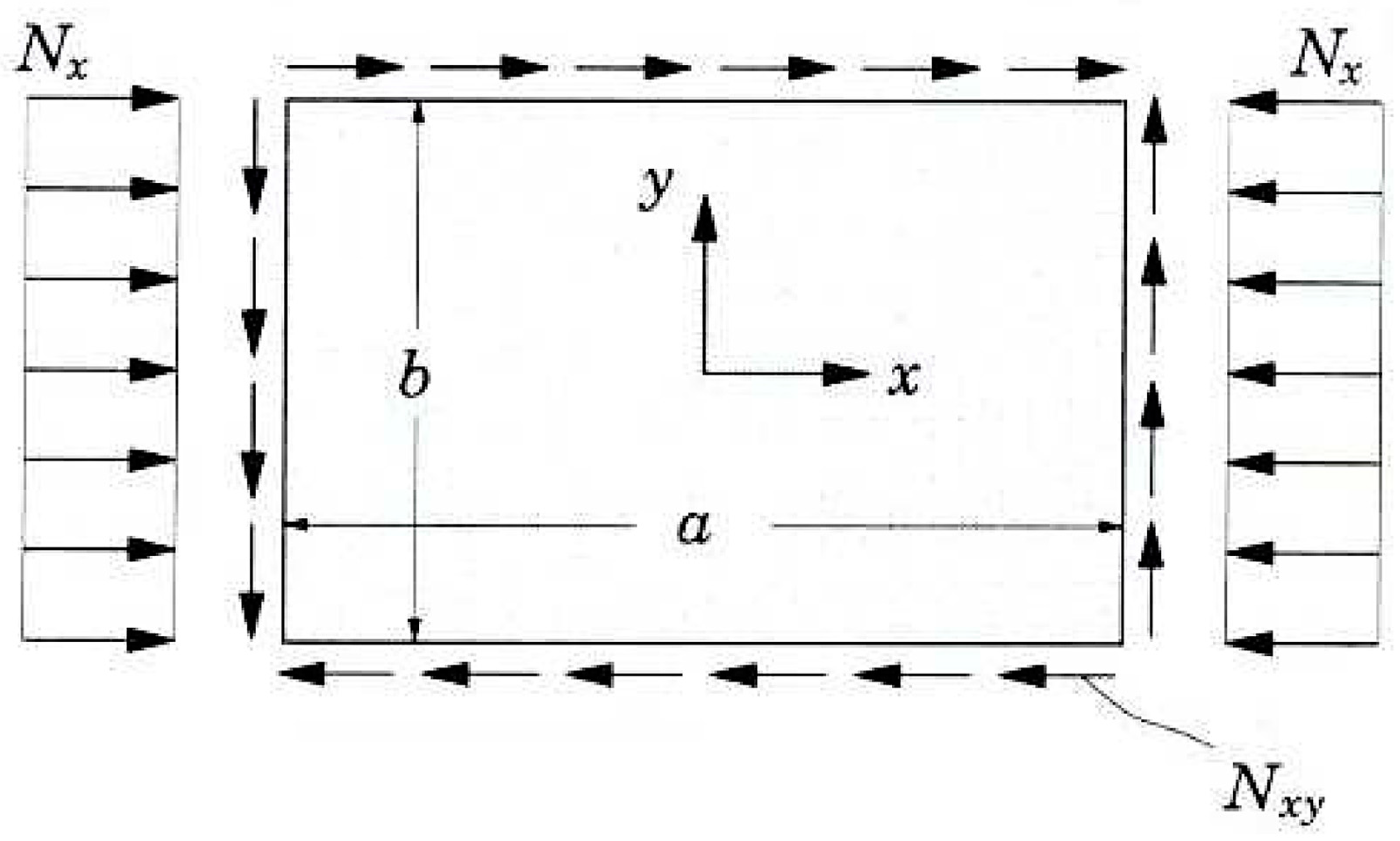
By considering a generic panel (a × b dimensions) of
Figure 16, this allows the introduction of the buckling of simply supported orthotropic plates under combined loads [
39,
40,
41]. The generic plate is simultaneously loaded with an
Nx uniaxial compressive load and an
Nxy shear load in the plane.
For the plate subjected to combined loads, we assumed the only applied loads were a uniaxial compression load in the x direction and an in-plane shear load. Introducing the constant,
μ:
For simply supported plates subjected to in-plane shear load, the boundary conditions have the following expressions:
where
ωmn,
xmn, and
ymn are the series coefficients, and
m and
n are positive integers. We now split the total potential energy functional for the Rayleigh–Ritz method into three parts (bending, shear, and external forces):
where
where
m ±
p and
n ±
q are odd numbers.
Substituting the Fourier approximations for
ω,
ϕx, and
ϕy gives:
Equilibrium of total potential energy requires that
δΠ = 0, thus:
m,
n,
p, and
q in Equations (8)–(10) are positive integers and run from 1 to ∞.
I10 is valid for
m ±
p,
n ±
q odd numbers; otherwise, zero. Equations (8)–(10) can be expressed in matrix form:
A simplified version of Equation (11) is given by:
Equation (12) is implemented in the optimization tool. To find the critical buckling load N, Multicella solves det[M X J] = 0. The accuracy of the result depends on the number of xmn, ymn and ωmn terms.
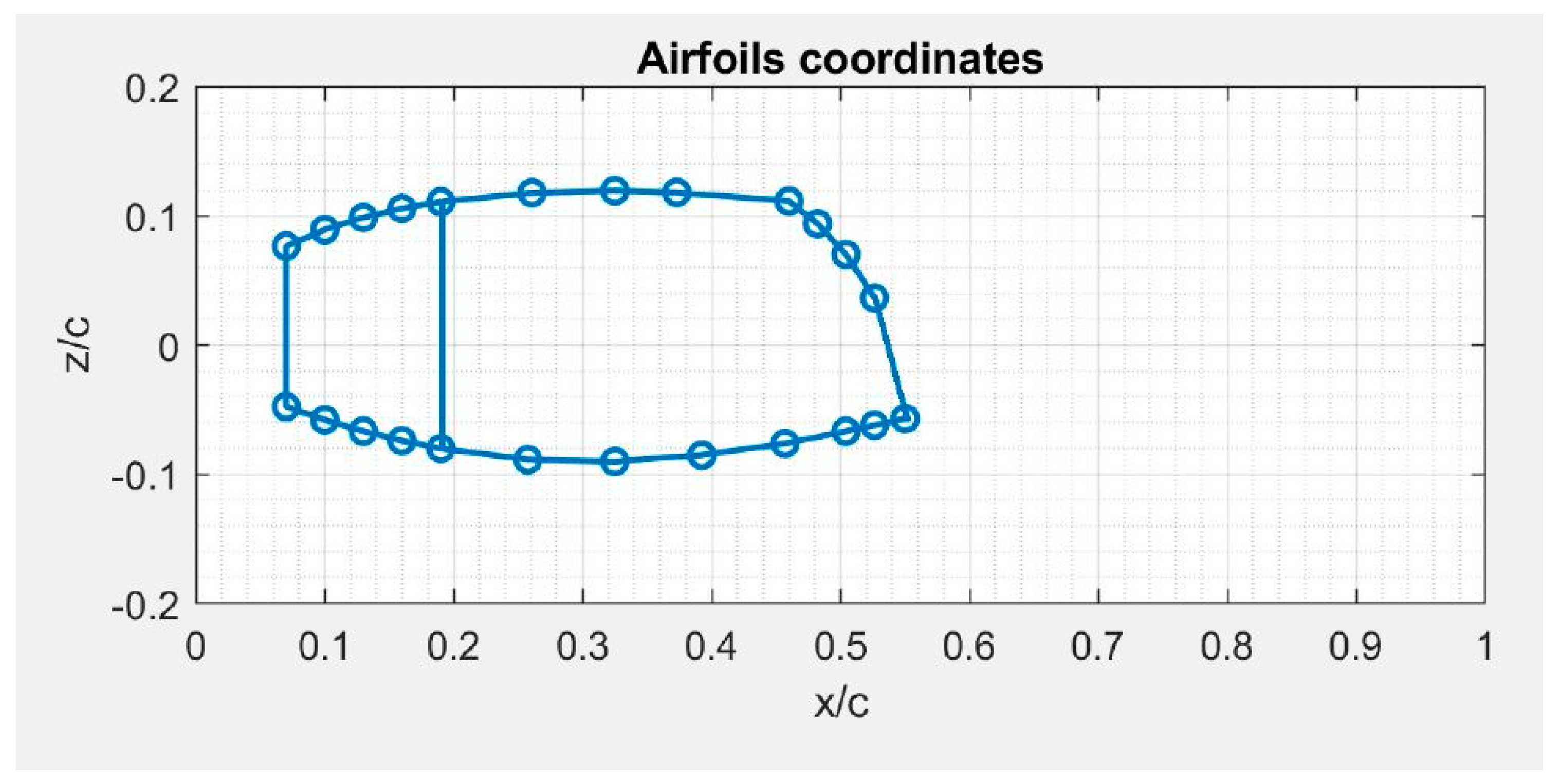
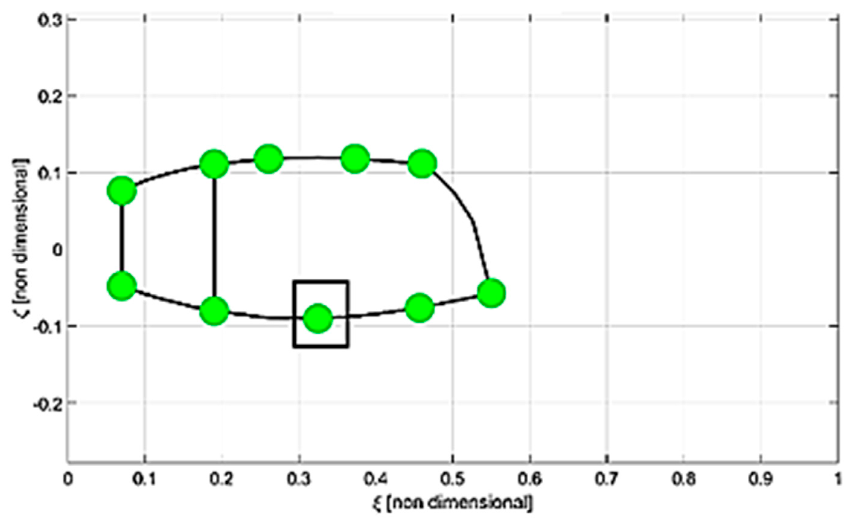
Figure 17 shows the airfoil of the wingbox as descripted by circle markers/coordinates. These points, opportunely grouped, represent the plates along the chord, i.e., in the plane of the airfoil, the thickness of which has been optimized for the buckling analysis.
Starting from an initial structural reference of the wingbox in terms of stiffness (M.S.) and structural weight, using the same materials and the same loads, the following examples of scalability with respect to buckling were carried out:
A. Geometric scalability: 30% chord increment.
B. Change in the dimensions of the panels subjected to buckling load: this is equivalent to inserting a stringer along the airfoil (as shown in
Figure 18).
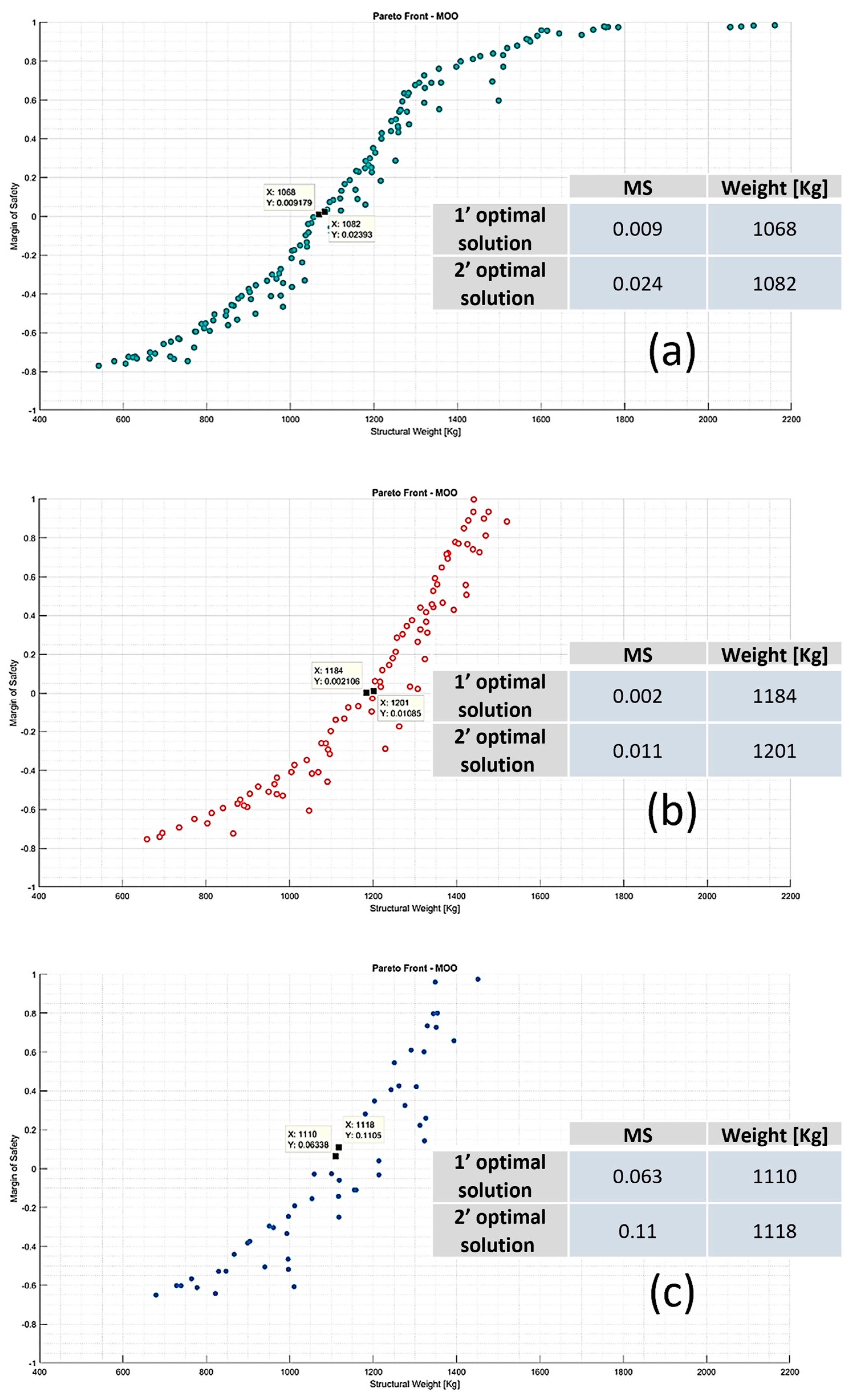
The Pareto fronts for the cases examined are shown in
Figure 19. In particular,
Figure 19a above relates to the reference starting wingbox, while
Figure 19b in the middle and
Figure 19c below relate to the cases of raising the string and inserting a stringer, respectively.
For each Pareto front, the two best optimal solutions in terms of MS and wing structural weights were considered.
In the first case, by increasing the chord length by 30%, the following are observed:
Since a linear increase in total weight does not correspond to an increase in the chord, it can be concluded that the optimization tool decreases the thicknesses of the panels as the stiffness increases.
In the second case, with a string increase of 30% and the insertion of an additional stringer, the following are observed:
a weight increase in the wing of about 4% compared to the reference wingbox.
a 6.5% decrease in the weight of the scaled wing with extra stringer, compared to the only up-scaled wing.
Therefore, the stiffening offered by the additional stringer is such that the optimization tool provides thicknesses to the structure, which overall is lightened.
7. Conclusions
In the present paper, a preliminary structural scalability assessment related to the wingbox of a tiltrotor was executed. Starting from the baseline wingbox, it was geometrically scaled up to a larger class of tiltrotor by preserving its structural concept (multi-spar configuration with an aft curved spar). Five different materials were considered in the analysis that solved a multi-objective optimization problem with respect to whirl flutter stiffness and crash requirements. The results show that the best solution (minimum-weight solution) was accomplished with high-modulus CFRP material. The geometrical scale factor that was used to upscale from the TD wing to the up-scaled version is equal to 1.289, whereas the ratio between the structural weight of the two best solutions (TD wing/up-scaled wing) resulted in 1.338, which is a value exceeding about 3.6% with respect to the geometrical scale factor (
Table 5).
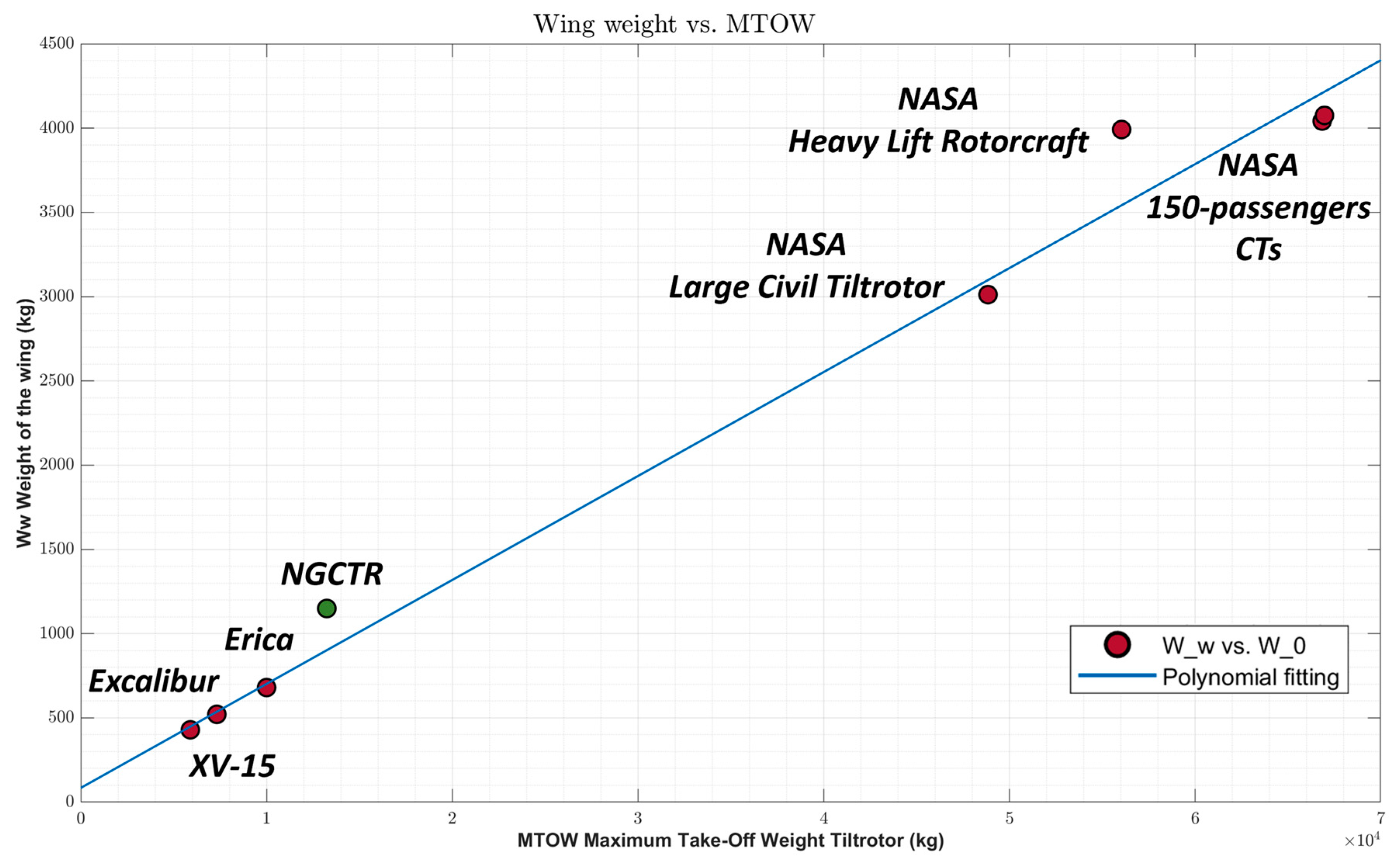
Figure 20 shows that the ratio between the structural weight of the wing and the design MTOW of the NGCTR is around 8.19%, which is higher than the average value referred to for other tiltrotors taken from the literature.
None of the existing tiltrotors was certified civil, and unfortunately, the wing weight data of certified tiltrotors are not accessible. Despite the high percentage of the up-scaled optimized wing with respect to NGCTR MTOW—which is over the trend—and based on the mature experience within the TD wing, it is deemed that a great margin of optimization can be achieved by using more refined tools (e.g., high-fidelity FEA) in the subsequent design phases of an up-scaled wing.

 ,
, 


