1. Introduction
Natural flyers have been our source of inspiration in man-made aircraft design since the successful flight of the Wright Flyer, which is heavier than air and marks the beginning of practically powered airplanes with sustained and controllable flight. In recent years, birds, bats, and insects have been investigated extensively because of the advent of micro air vehicles (MAVs) in military and civilian applications [
1,
2,
3,
4,
5]. In contrast to conventional airplanes, these MAVs usually operate at a low Reynolds number regime of 10
5 or lower, which presents a number of challenging aerodynamic problems such as massive laminar flow separation and laminar-to-turbulent transition [
6,
7,
8]. However, for natural flyers which operate in the same Reynolds number as MAVs, their aerodynamic performances seem to be superior to these man-made MAVs [
6,
9]. Therefore, it is urgent to understand the outstanding aerodynamic performance to provide useful insights in developing a more efficient and more stable MAV design.
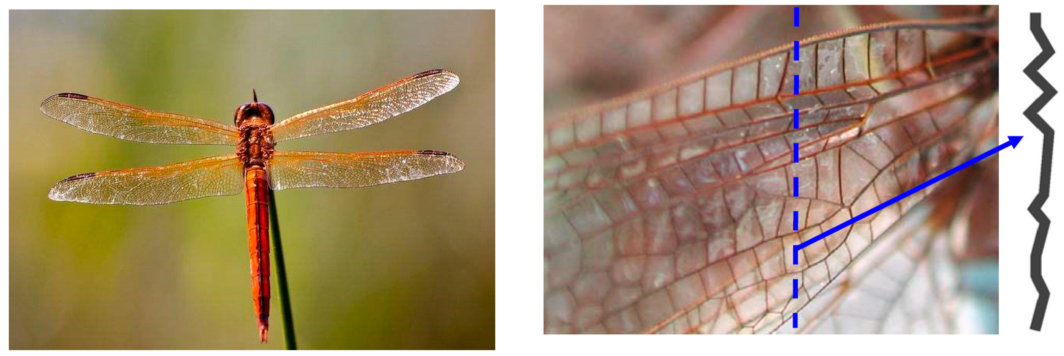
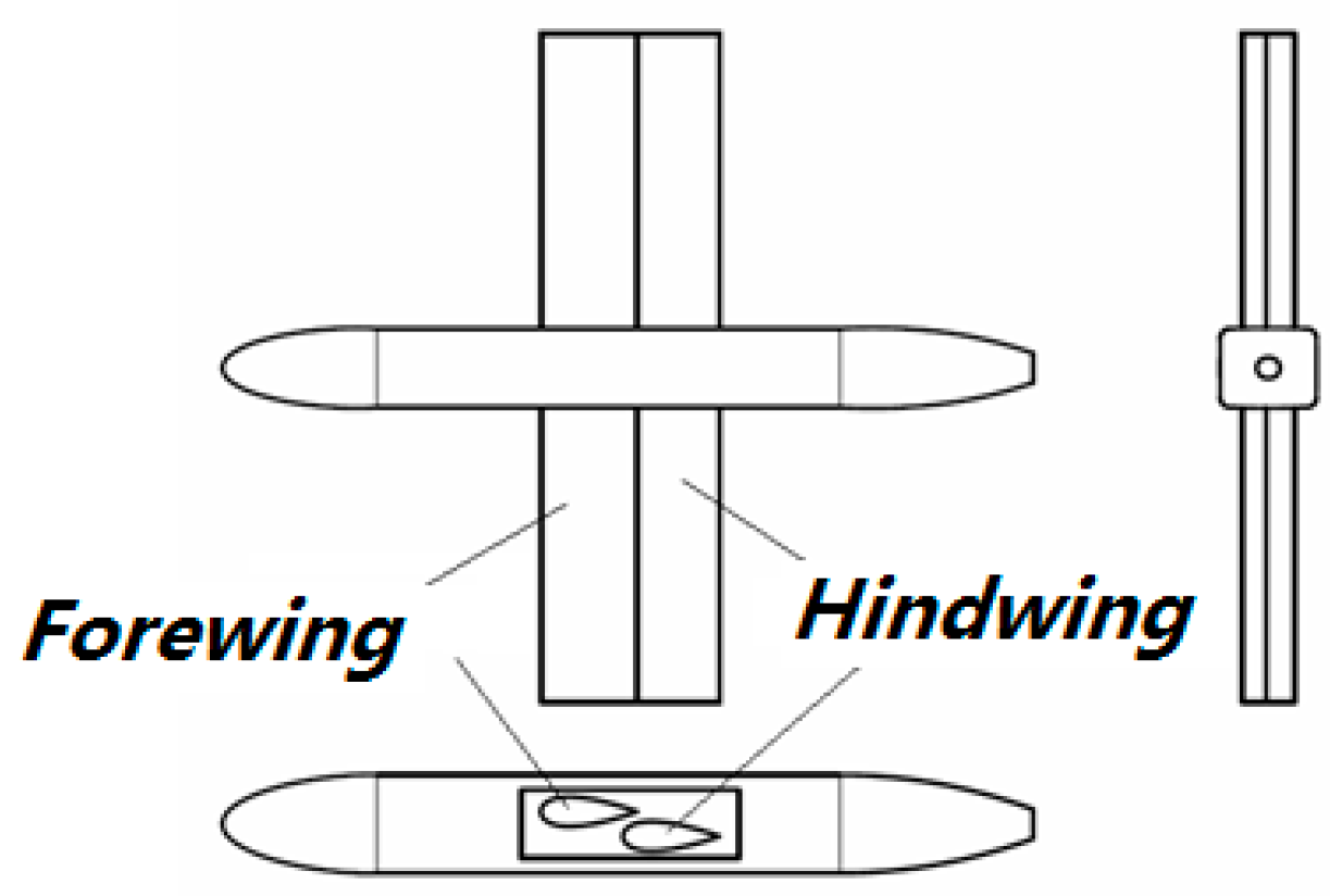
Dragonflies (see
Figure 1) have excellent flying capacity. They are one of the fastest and most maneuverable flying insects, so it is an important imitation object in MAV design [
9,
10]. The tandem configuration and wing corrugation are two distinct features of dragonflies compared to traditional man-made aircraft [
9]. So in this paper, the possibility of using tandem wing and corrugation on new concept MAVs to improve their aerodynamic performance compared to traditional aircraft is checked both experimentally and computationally.
For man-made flight vehicles, they generally have one pair of symmetrical wings. However, for natural flyers, some of them have two pairs of wings, such as dragonflies, butterflies, or bees, and their flight dynamics are greatly influenced by the wing—wing interactions. Two pairs of wings could produce a variety of aerodynamic improvements such as increased lift and thrust, and gust resistance. However, the unsteady flow interactions between two closely situated wings is far more complicated than conventional single wing [
9]. Recently, tandem wing has been extensively studied using experimental [
11,
12,
13,
14] and numerical [
15,
16,
17,
18,
19,
20,
21,
22,
23] methods in order to understand the superior flight performance of the tandem configuration. Borering et al. [
15,
16,
17] and Rival et al. [
18] investigated the phase angle and spacing effect on tandem wings numerically. Lian et al. [
9] investigated various phase angles of forewings and hindwings, and the aerodynamic characteristics of tandem wings under gusty conditions and compared them with isolated wings. They demonstrated that the gust resistance characteristics of flapping wings in different configurations. Generally, all of these results indicate that tandem configurations could have better aerodynamic performance with appropriate arrangements.
Dragonfly wings are typical 2-dimensional composite materials in micro-scale (see
Figure 1). The special vein-membrane structure makes the surface of the wing corrugated, while man-made airplanes always have a smooth wing surface. Various investigations demonstrate that these corrugated structures improve structural performance [
9,
24,
25,
26], however, there is not an agreement about the aerodynamic effect of the corrugation. Some results conclude that the corrugation can increase lift [
27], aerodynamic efficiency (defined as the ration of lift to drag) [
28,
29], or decrease drag [
30], however, other explorations indicate that the corrugation has no aerodynamic effect and could be replaced directly by a smooth plate [
31,
32,
33].
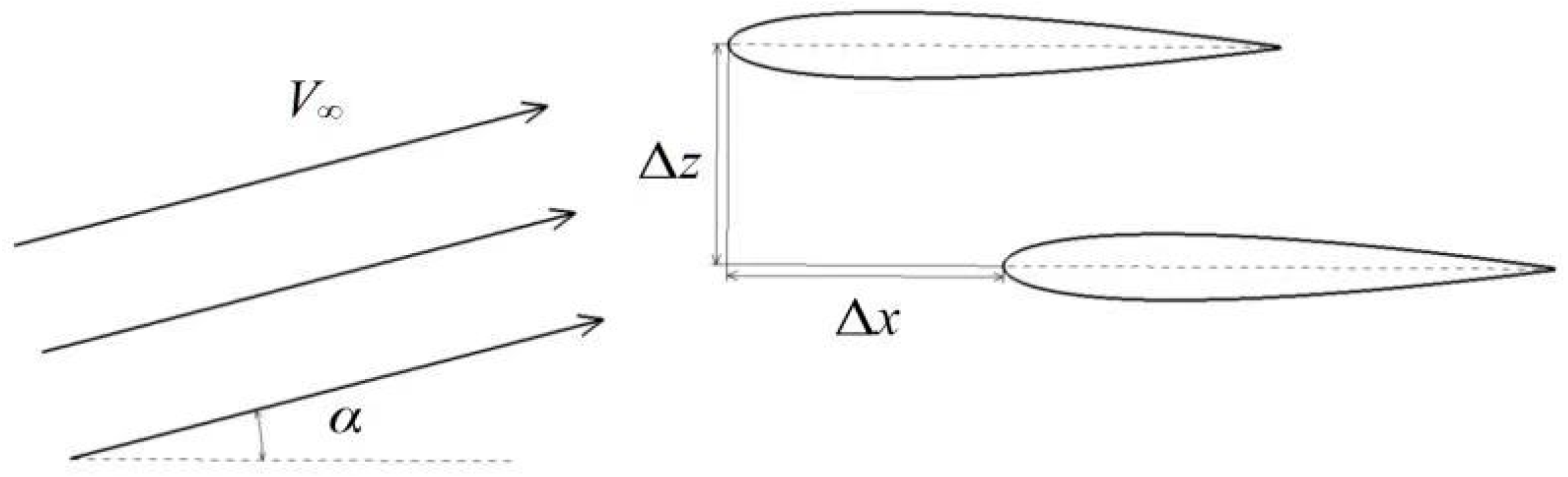
The purpose of this paper was to investigate the possibility of tandem configurations (see
Figure 2 for details) for MAV design, to explain the lift enhancement of the new concept quantitatively, and then to try to ascertain the effect of airfoil thickness and, the decalage of the hindwing on the overall aerodynamic characteristics. In addition, the effect of the surface corrugation has been simulated numerically, considering that the surface of the flexible wing usually could not be as smooth as a rigid wing structure because of the airproof and rigid requirements for inflatable structures. As a preliminary design for MAVs, a fixed wing rather than a flapping configuration has been considered to reduce the unsteady flow complexity caused by the flapping motion of the wings.
2. Experimental Apparatus and Procedure
In order to demonstrate the effectiveness of tandem wing configurations, seven different kinds of flat wings have been manufactured and tested at a freestream velocity of 20 m/s with a chord-based Reynolds number of approximately 1.2 × 10
5.
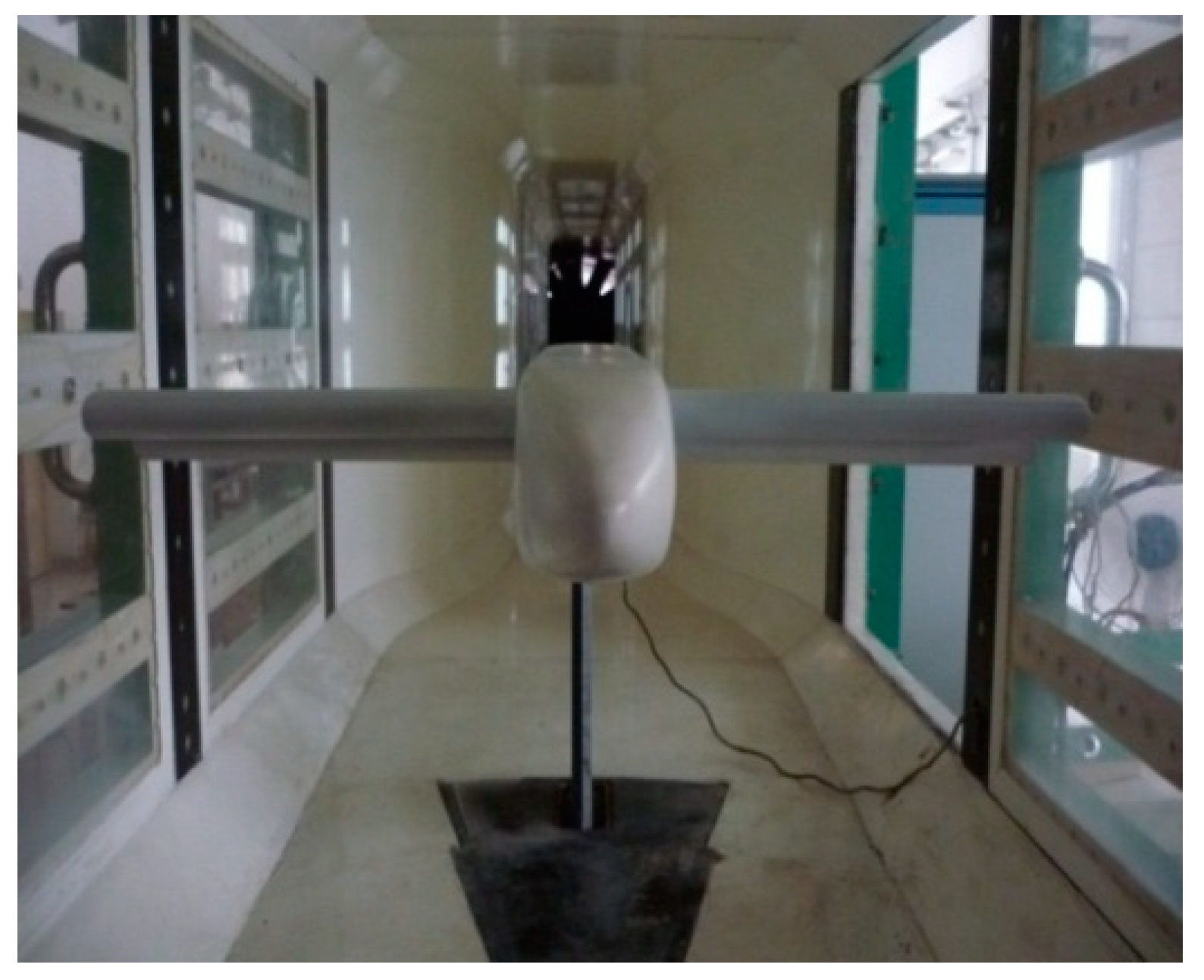
Figure 3 shows an experimental model fixed in the wind tunnel.
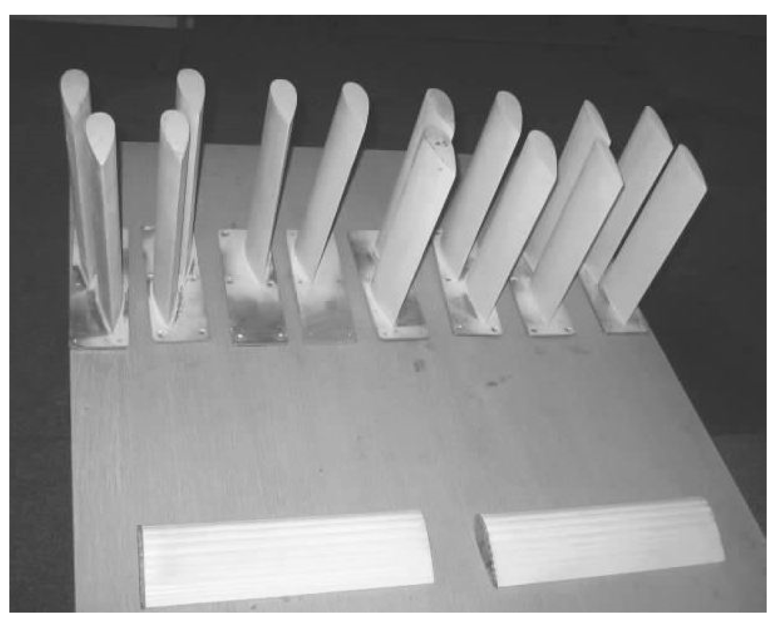
Figure 4 illustrates some of the experimental wings. All of the models for tandem wing configurations were conducted in the low turbulence wind tunnel (LTWT) located in the Northwestern Polytechnical University (NPU) in Xi’an, China. This wind tunnel is an open circuit low speed, low turbulence wind tunnel with a working section that is 1200 mm wide, 1050 mm high, and approximately 2800 mm long [
13,
21]. The maximum turbulence intensity of the wind tunnel is 0.02%, and the available flow speed range of the LTWT is about 5–25m/s [
13,
21]. The testing range of the angle of attack is from −4° to 16° at an interval of 2°. When mounted in the working section, the maximum blockage ratio of the full model to the wind tunnel is less than 4.0% for the airspeed considered in this work [
13,
21].
For all the models, a six-component strain gauge balance has been used for force measurement. The measuring ranges for aerodynamic lift and drag are 196 N and 68.6 N respectively, with an accuracy of 0.6% [
11,
19]. To weaken the strut interference in the wind tunnel, the model has been rear-sting supported in the wind tunnel.
A three-view drawing of the model studied is presented in
Figure 5. As can be seen in the figure, the same airframe has been used for all the experimental models. From
Figure 5, it is shown that all the wings are attached in an end rectangular plate, then the plate is fixed rightly in the rectangular groove of the airframe by four bolts in the four corners. There are two main airfoils for these wings, which are thick airfoil NACA0030 and thin airfoil NACA0015. Based on these two profiles, seven different kinds of wings are built, including (1) a single wing configuration with a thin airfoil, (2) a double wing configuration with a thin airfoil, (3) a single wing configuration with a thick airfoil, (4) a double wing configuration with a thick airfoil, (5) a single wing configuration with a wavy airfoil based on NACA0030, (6) a double wing configuration with a wavy airfoil based on NACA0030, and (7) a double wavy wing configuration with 2°decalage of hindwing about its quarter chord. As can be seen from
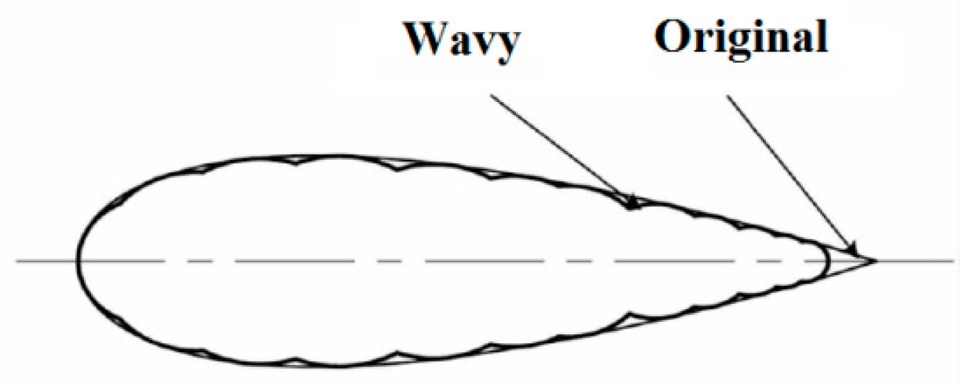
Figure 6, a wavy airfoil is composed of 22 arcs which are internally tangent to airfoil NACA0030. Detailed information could be found in Hua’s experimental studies [
13]. For all the tandem wing configurations, the hindwing is fixed 0.09 m posterior chordwisely and 0.025 m lower vertically compared to the forewing.
For all the experimental models, the projected area of its flat wings is selected as the reference area. Because the chord length is 100 mm, the semi-span is 295 mm, so the reference area for the lift coefficient and drag coefficient for single wing configurations is 0.059 m2, while it is 0.118 m2 for tandem wing configurations. The wind tunnel experiments were carried out at a Mach number of 0.0575 at an angle of attack up to 16°, while the free stream velocity is 20 m/s, and the pressure and temperature of free stream are 95.19 KPa and 300.65 K, respectively.
3. Computational Method Setup
Due to the limitations of wind tunnel experiments in providing a detailed flow field, computational simulations have been conducted for the seven configurations mentioned above. In addition, to demonstrate the high efficiency of lift increase in hindwing decalage, a double wavy wing configuration with decalage of 4° was simulated numerically. It should be noted that the decalage angle is defined as the angle of the hindwing chord line compared to the forewing chord line.
3.1. Geometric Models and Computational Grids
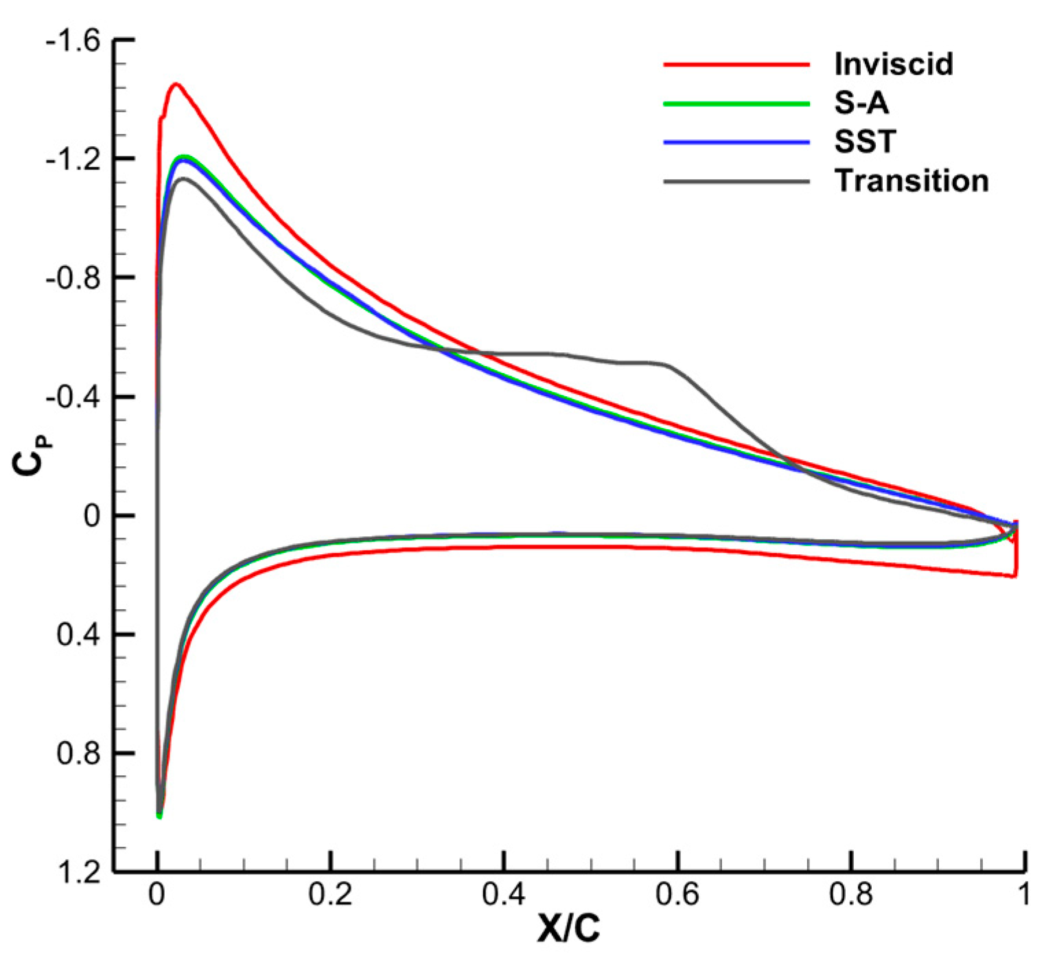
In order to validate the accuracy and reliability of the numerical tools employed in this study, a comparison of SD7003 airfoil surface pressure distribution at angle of attack 4° and Re 6 × 10
4 was made between our in-house codes and the method in [
34], as shown in
Figure 7. It can be seen from the figure that the two lines almost overlap with each other.
Table 1 shows the detailed comparison of lift and drag between different turbulence models. Considering the small difference between the S—A and reference values, it was concluded that the Spalart—Allmaras (S—A) one-equation turbulence model would be adopted in computational calculations of this paper to simulate the flow field in low Reynolds numbers.
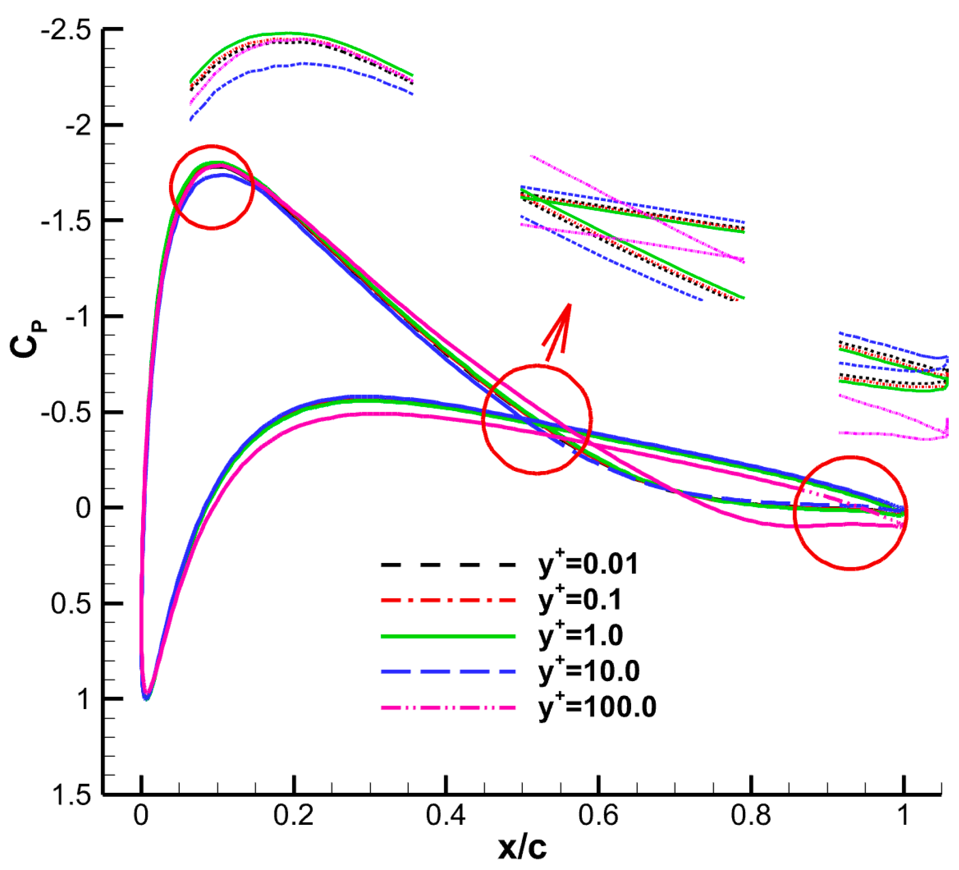
In
Figure 8, the computational validations show that y
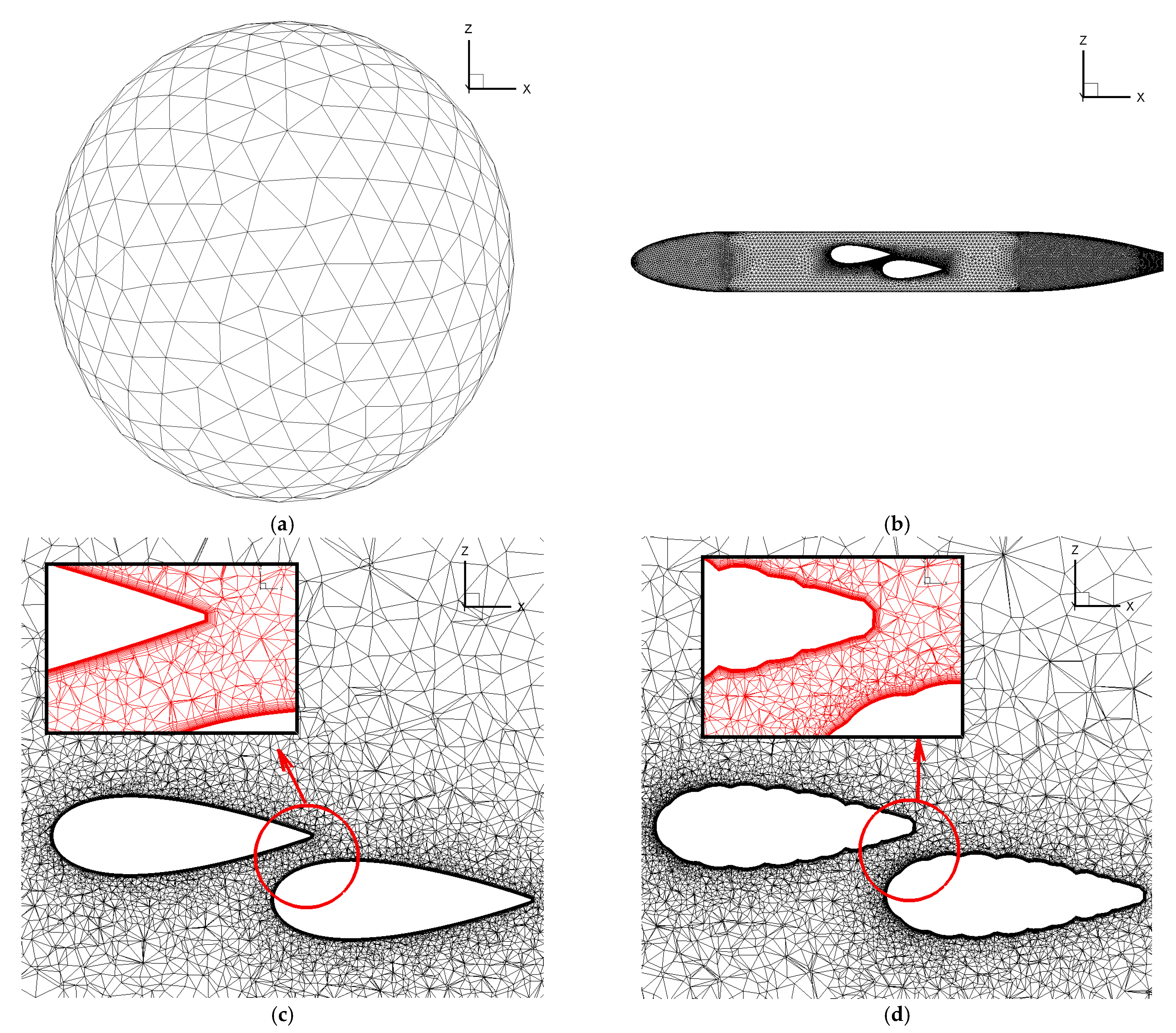
+ = 1.0 is accurate enough to obtain convergent results. Unstructured computational meshes have been generated in the numerical calculations, as
Figure 9 displays. In general, it is a hybrid unstructured grid that consists of triangular prisms in the boundary layer and tetrahedral cells in the outer fluid zone for the full grid. Most of the grid points are clustered in the boundary layers. The total number of boundary layers is 31. The first boundary spacing off the wall has been selected in order to achieve a y
+ value of 1.0.
3.2. Numerical Simulations
All computations were conducted using our in-house Navier-Stokes flow solver F
2M (Solver of Flight-dynamics for Flexible Multi-body) which is described in detail in Hua’s work [
35,
36] and Li’s work [
37,
38]. It is a finite-volume CFD code that solves Navier-Stokes equations on unstructured grids. Several turbulence models were implemented, including algebraic, one-equation, two-equation, and five-equation models. All computations were carried out under a “fully turbulent” assumption, while the Spalart—Allmaras (SA) one-equation turbulence model was adopted in computational calculations for this paper. For all the computations, results were believed to have converged when all the residuals were less than 10
−5.
For all of the simulations, two kinds of boundary conditions were considered: “no slip” and “adiabatic” boundary conditions for the wall, including airframe and all the wings, and “free-stream” conditions for the far-field, while the far field was a sphere with a diameter of 40 m.
4. Results and Discussions
In this section, the effect of airfoil thickness, the effect of surface waviness, and the effect of hindwing decalage are investigated and presented in detail based on numerical solutions of the flow around these configurations with tandem wings.
4.1. Effect of Airfoil Thickness on Aerodynamic Characteristics
For aircraft with inflatable wing structures, there are only internal spars and flexible outer skin to maintain aerodynamic shape and structural integrity after inflating. The stiffness and strength of inflatable structures mainly depend on the profile of the wing cross section and the pressure difference between the internal air and the outer atmosphere, so in order to meet these structural requirements, thick airfoils are preferred in the design of the inflatable wings. However, compared to thin airfoils, aerodynamic performance is less efficient for thick profiles. To improve the aerodynamic efficiency of the inflatable wings with thick airfoil, tandem configuration is presented in this paper.
In this section, the aerodynamic characteristics of tandem configurations with both thick and thin airfoils have been compared to describe the advantages of thick tandem wings, and it should be noted that for both of the thick and thin wings, the relative position of the hindwing compared to the forewing is fixed, as described in Hua’s work [
13].
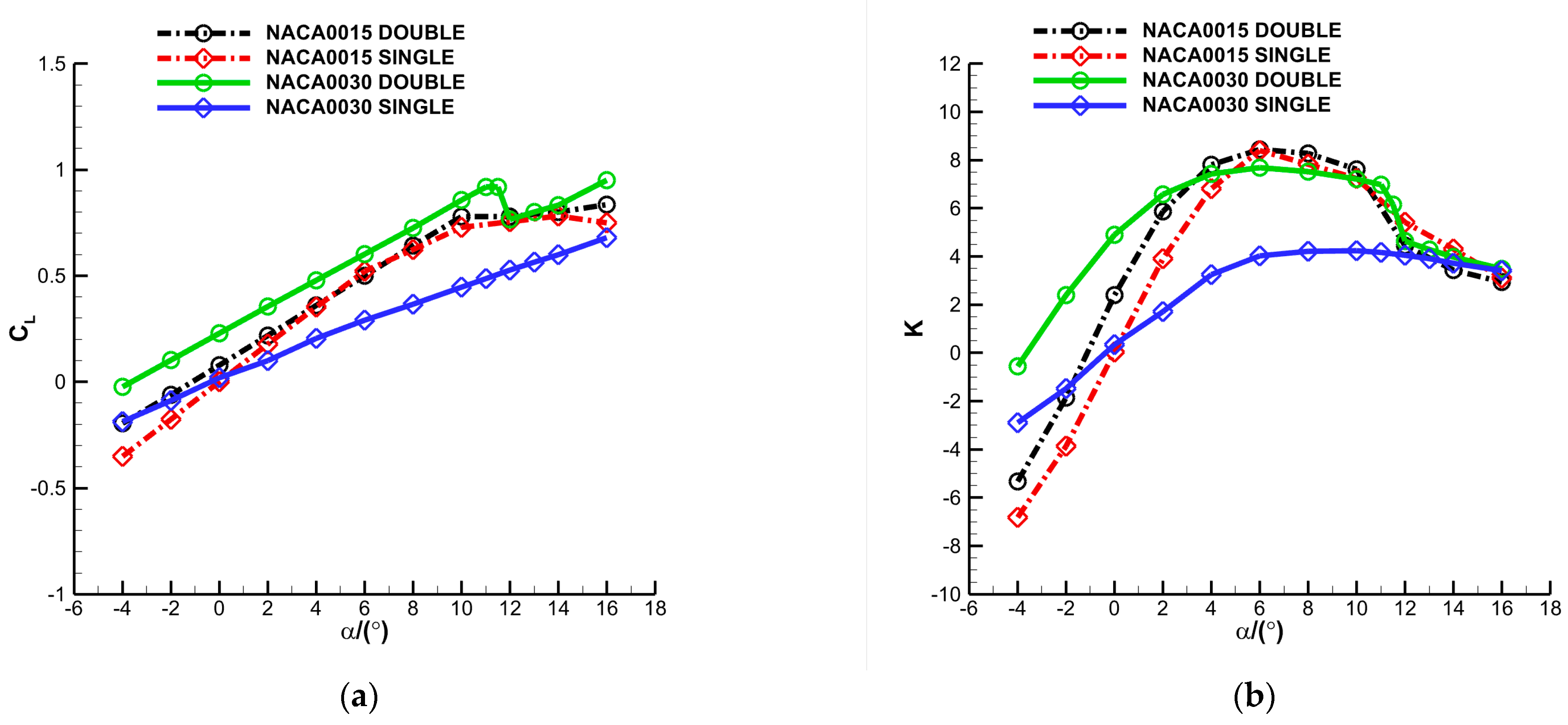
Figure 10 illustrates the computational comparisons of aerodynamic coefficients for configurations with thin or thick wings. As shown in the figure, for the fixed positions of the two wings of a tandem configuration, the lift and aerodynamic efficiency of a thick tandem configuration improve significantly compared to a thick single configuration at angles of attack lower than 10
° while there are no significant enhancements for thin configurations (apart from angles of attack between −4° and 2°). These conclusions could revalidate the fact that improvements of aerodynamic efficiency for tandem thick configurations compared to single thick configuration are evidently greater than the corresponding values for thin configurations. The greatest percentage of aerodynamic efficiency improvement for a tandem thick configuration compared to a single thick configuration is 1376% at angle of attack 0°, while it is 52% for a tandem thin configuration compared to a single thin configuration.
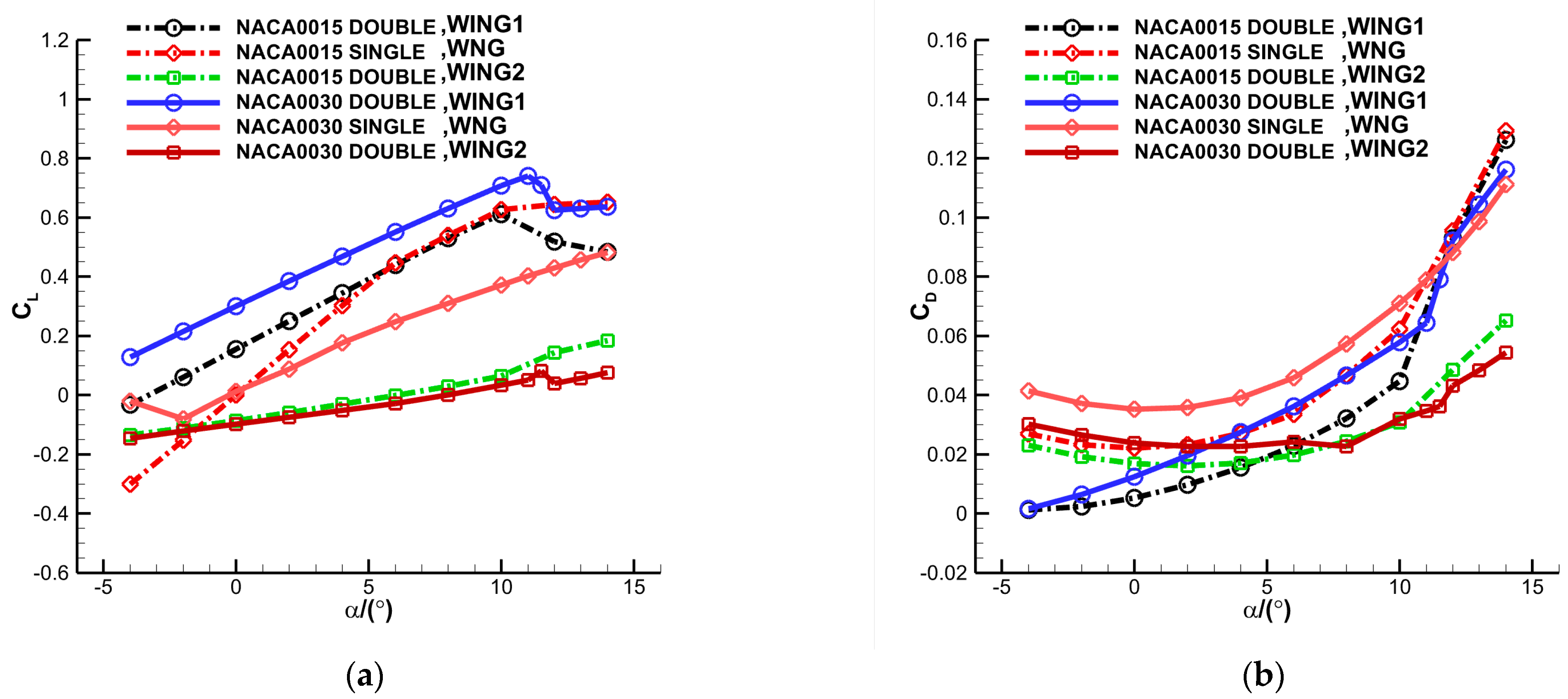
In order to understand the mechanism of lift enhancement for tandem configurations, lift and drag coefficients for every wing of the tandem configuration are exhibited in
Figure 11. As can be seen in the figure, because the free stream velocity is very low, wing drag generally increases with its thickness and the angle of attack before stalling. Furthermore, for the tandem configuration, the drag of the forewing or hindwing is smaller than the single wing configuration, but their sum shows similar value with single wing configuration. As for the lift, the forewing of the tandem thin configuration shows an evident increase only when angle of attack is lower than 4°, and because the lift of the hindwing is very limited, the net lift of the tandem thin configuration only shows a little improvement when the angle of attack is lower than 4°. However, in the experimental range, the forewing of the tandem thick configuration always shows a significant increase, so the overall aerodynamic efficiency improves more evidently compared to the single thick configuration.
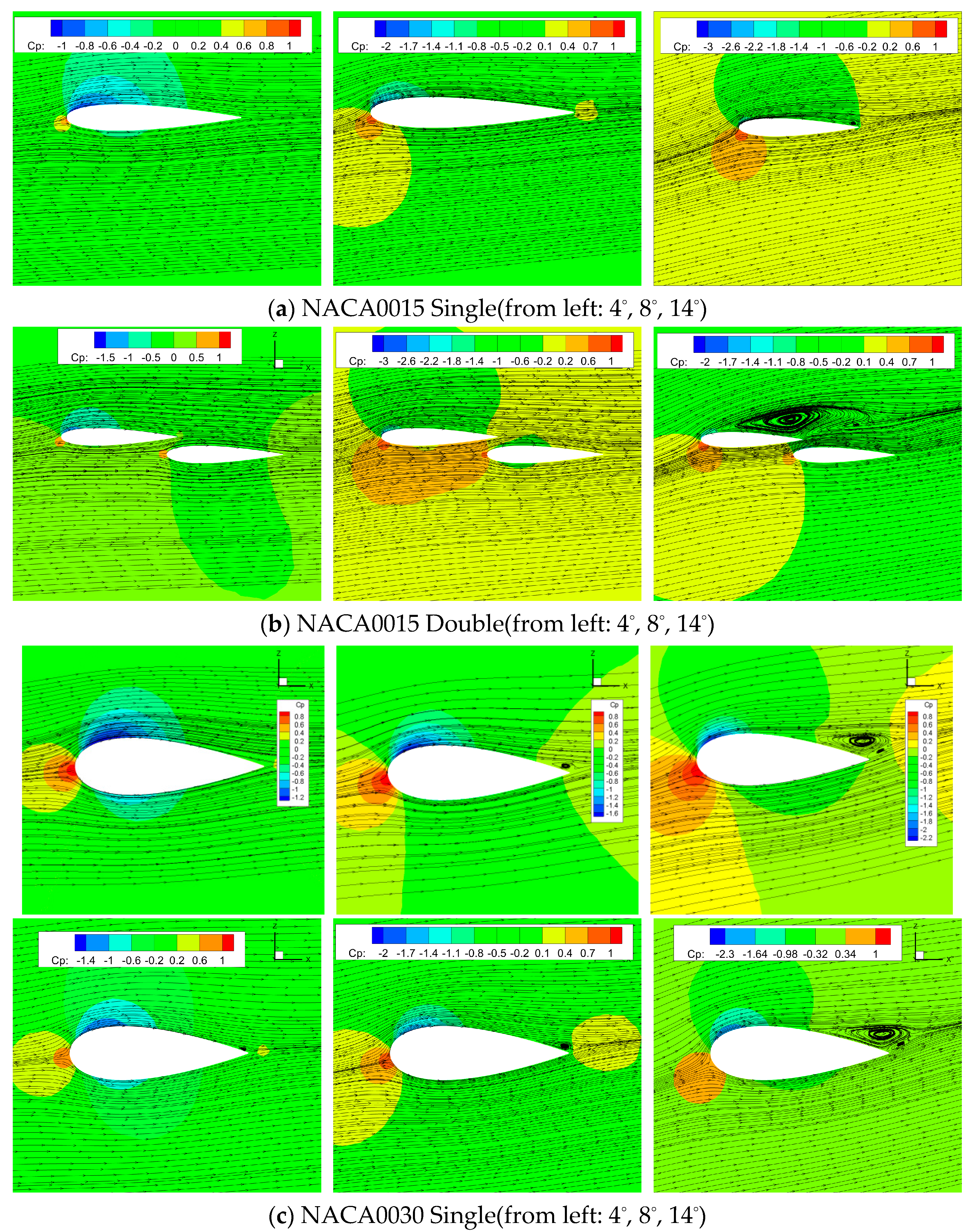
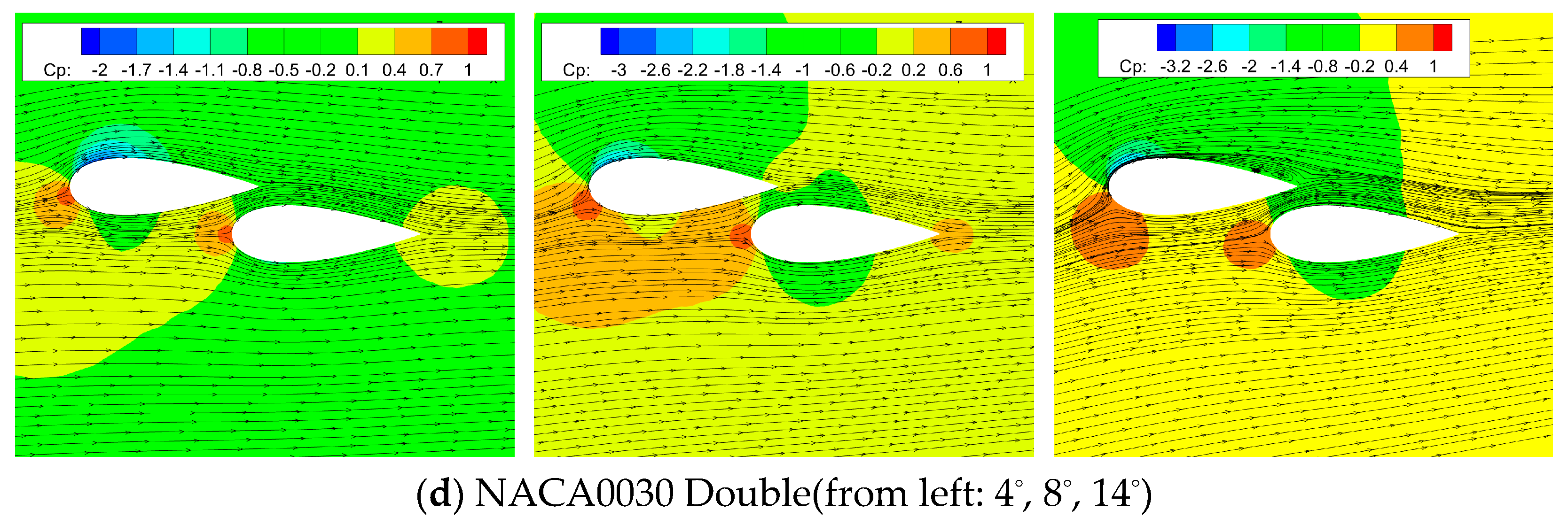
Figure 12 gives the streamlines and pressure contours of single and tandem thin and thick configurations at 50% of the semispan at three typical angles of attack, 4°, 8°, and 14°, and it could be employed to explain the reason for the stalling angle decrease for the tandem thick configuration. At a larger angle of attack 14°, both the flow fields of the thin (
Figure 12a) and thick(
Figure 12c) configurations show apparent separation, and the separation zone is more obvious for thick configuration. For the tandem thin configuration in
Figure 12b, the visible separation zone appears much larger than the separation zone in
Figure 12a, but for the tandem thick configuration in
Figure 12d, the vortices nearly disappear because of the accelerating effect of the narrow gap between the two wings that suppresses the separation.
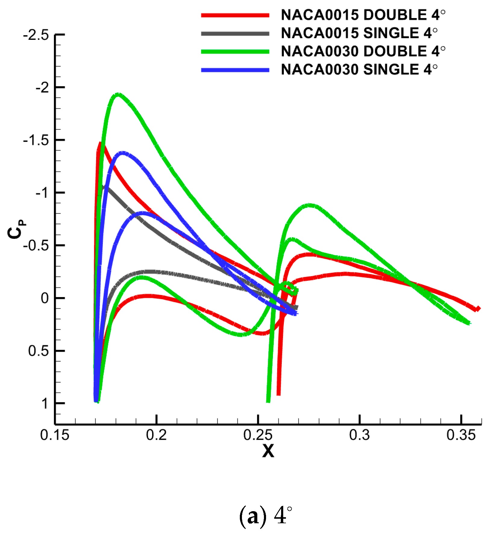
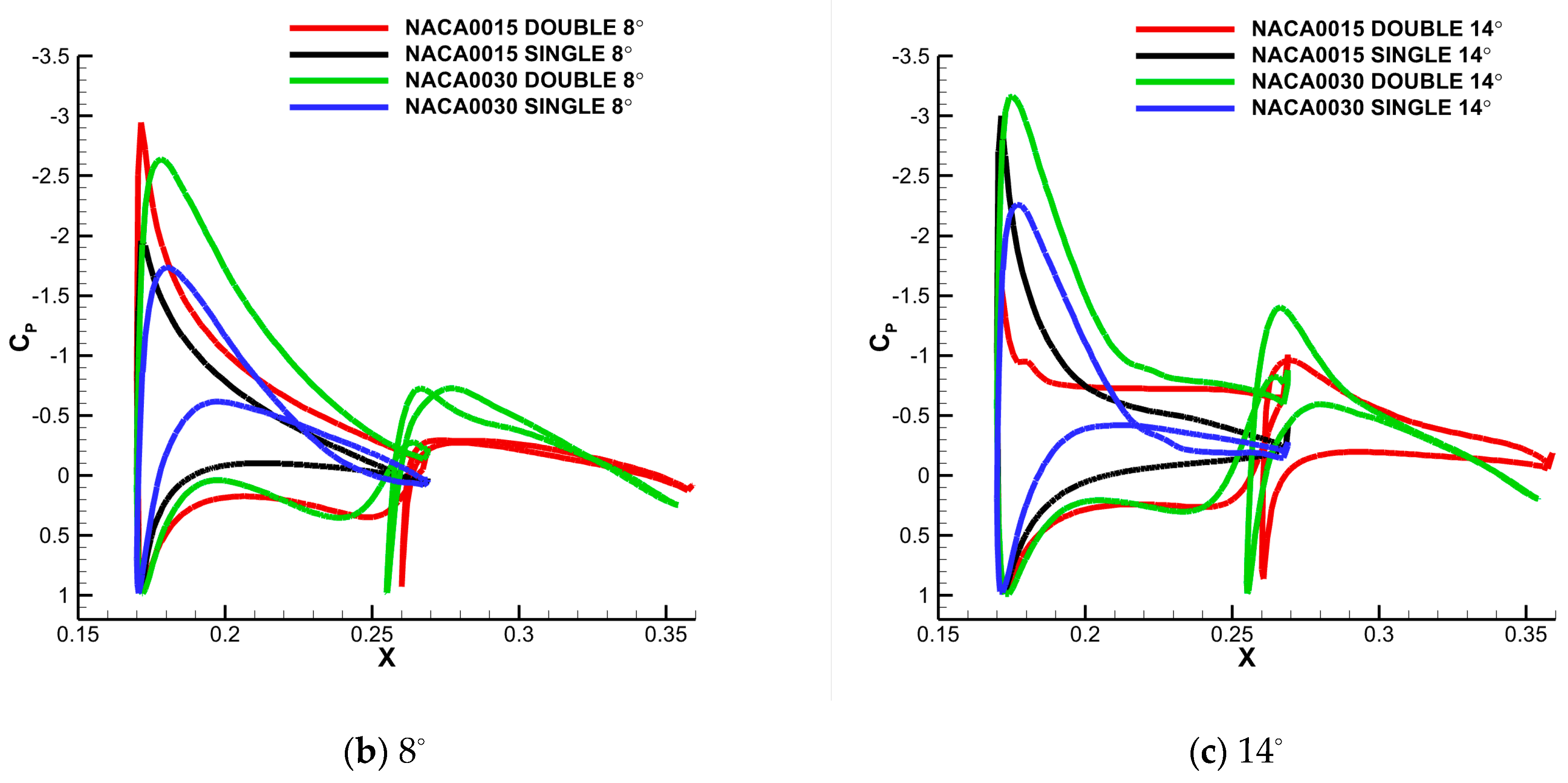
Figure 13 displays the pressure distributions of the wing surface at 50% of the semispan of single and tandem configurations at three typical angles of attack. The effectiveness of tandem thick wing configuration on lift enhancement could be explained explicitly by these figures. When the angle of attack is 4° for the tandem thin configuration, pressure increases distinctly on the lower surface of the forewing compared to the single configuration, but pressure on the upper surface shows little decrement, so the lift of the forewing increases slowly. In addition, the pressure difference between lower and upper surfaces of hindwing seems a little smaller than the single wing, so the overall lift of the tandem thin configuration gains a little compared to the single wing configuration because of the averaged effect of the two wings. However, for the tandem thick configuration, both the pressure increment on the lower surface and the pressure decrement on the upper surface are distinct compared to single thick wing, so the overall lift increase is evident. At 8°, because the lift of the hindwing decreases significantly due to the blocking effect of the forewing, the overall lift of both tandem thin and thick configurations drops abruptly. At 14°, for the tandem thin configuration, large scale separation appears at the upper surface of the forewing, so the overall lift of the configuration seems much smaller than that of the single thin wing. For the tandem thick wing, the accelerating effect suppresses the large scale separation of the forewing, so the lift of the forewing is larger compared to that of the single wing configuration. However, the lift of the hindwing decreases a great deal due to the blocking effect of the forewing at a large angle of attack. Thus, the overall lift shows little improvement for the tandem thick configuration.
4.2. Effect of Surface Waviness on Aerodynamic Characteristics
For inflatable wings, the surface of the structure could not be as smooth as traditional metallic wings due to structural requirements. Some investigations have shown that sinusoidal leading edges could help to control the stalling phenomenon at high angles of attack [
39,
40]. In order to understand the effect of these corrugated surfaces on the aerodynamic characteristics, computational simulations were carried out to analyze the flow fields around these corrugated wings.
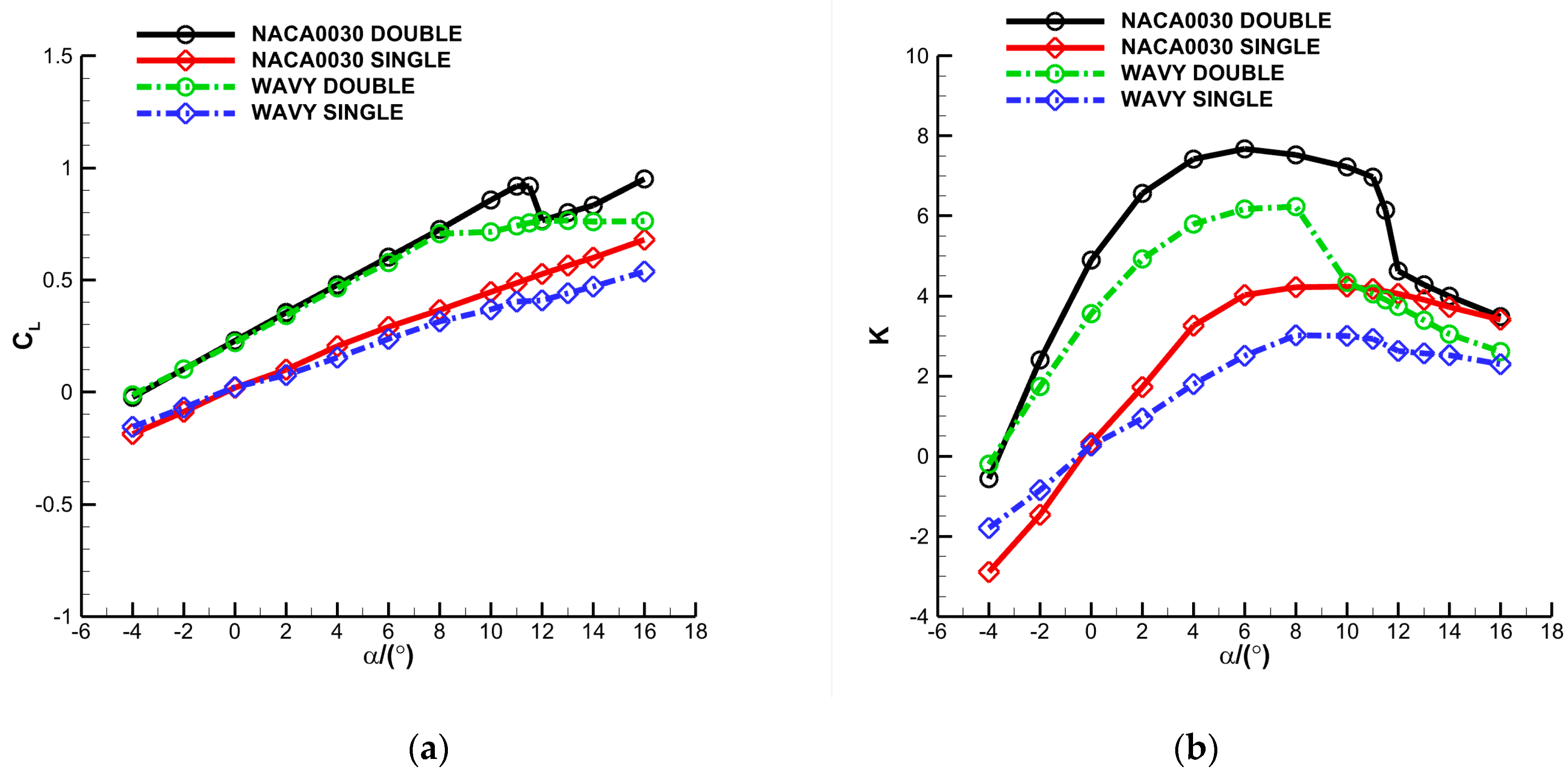
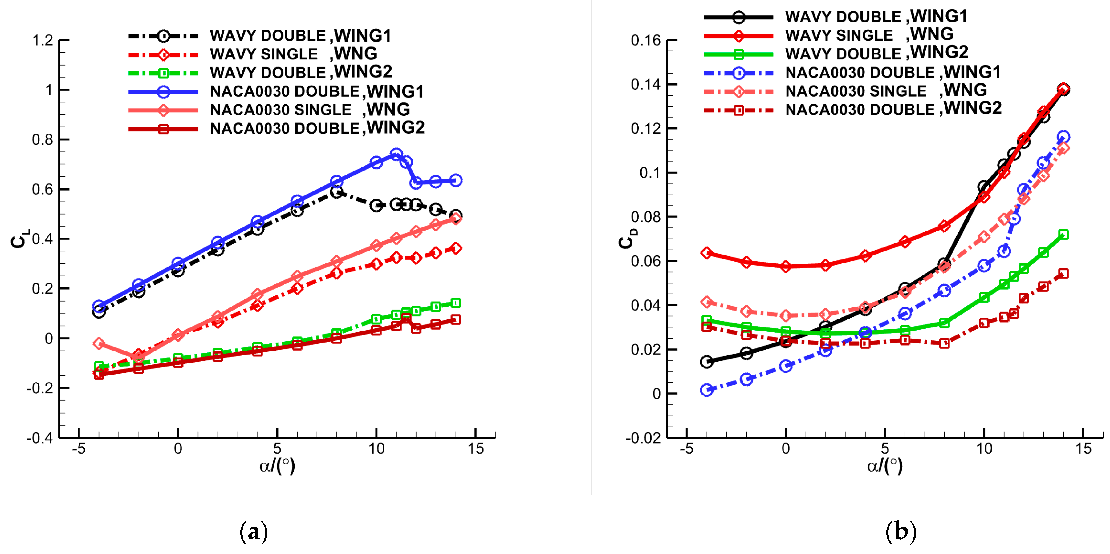
Figure 14 illustrates the computational comparisons of aerodynamic coefficients for configurations with smooth or wavy wings. As shown in the figure, the lift and aerodynamic efficiency of smooth and wavy wings show no clear variation at low angles of attack. Both the tandem configurations of smooth and wavy wings exhibit a better aerodynamic performance compared to corresponding single configurations at low angles of attack. However, for the tandem smooth configuration, there is an abrupt drop of lift immediately after stalling, while the lift remains nearly constant for the wavy configuration. The reason can be clearly seen in
Figure 15,
Figure 16 and
Figure 17 later. It shows that the improvement of aerodynamic efficiency for the tandem wavy configuration compared to the single wavy configuration is evidently greater than smooth configurations at low angles of attack from 2° to 16°.
These results can be validated by
Figure 16 where lift and drag coefficients for every wing of the tandem smooth and wavy configurations are compared quantitatively. For single smooth and wavy wing configurations, because the drag of wavy wing is much bigger due to its bigger surface while the lift is a little smaller due to standing vortices in the troughs, the aerodynamic efficiency of the wavy wing is much smaller than smooth wing. For tandem wavy configurations, the forewing lift increment and drag decrement of the two wings are both evident compared to the single wavy wing, so the aerodynamic efficiency improves a great deal. For tandem smooth configurations, the aerodynamic efficiency generally improves due to the significant lift increment of the forewing, but the increasing percentage is not as significant as that of the tandem wavy configuration because the aerodynamic efficiency of the single smooth wing is much higher than the single wavy wing.
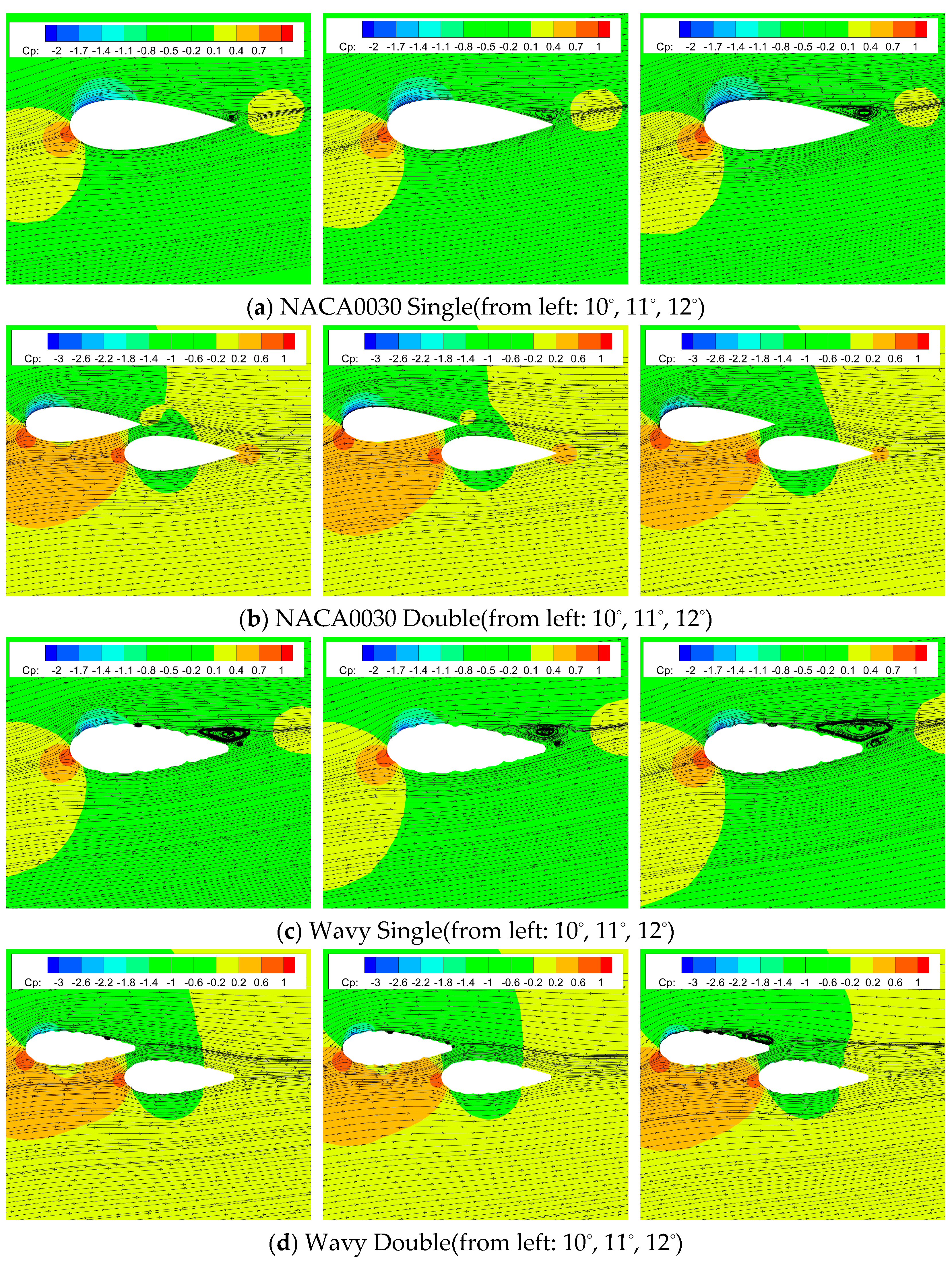
Figure 17 gives the streamlines and pressure contours of single and tandem smooth and wavy configurations at 50% of the semispan at three typical angles of attack, and it can be used to explain the reason for the stalling angle decrease for the tandem wavy configuration. At these three angles of attack, both the flow fields of the single smooth (
Figure 17a) and wavy (
Figure 17c) configurations show separation, especially at 12°. For the tandem smooth configuration in
Figure 17b, the accelerating effect of the gap of the two wings makes the visible vortices disappear in
Figure 17a, but for the tandem wavy configuration in
Figure 17d, the vortices are lessened without disappearing because at every trough, it is easy to generate vortices. Thus, the wavy configuration will stall at a lower angle of attack than the smooth configuration will because of lift losses caused by vortices.
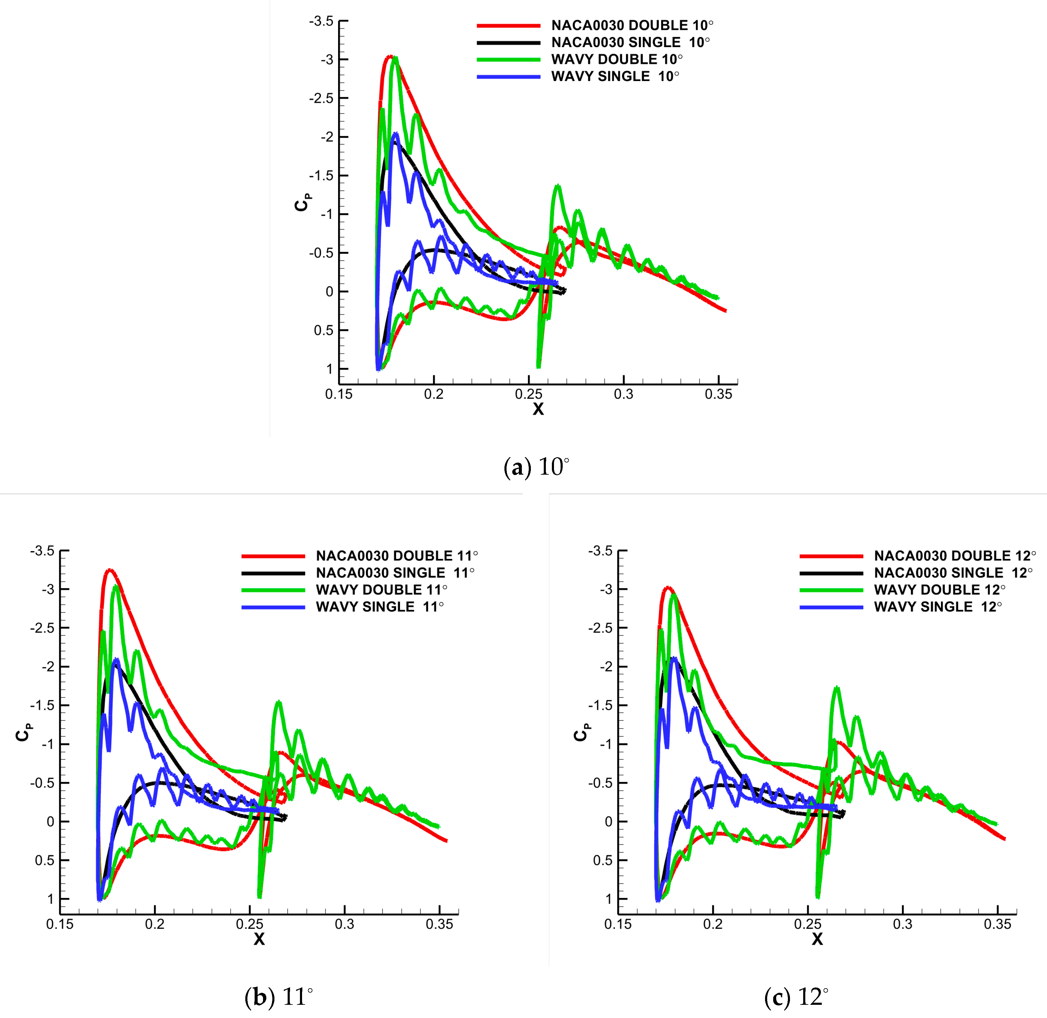
Figure 17 displays the pressure distributions of the wing surface at 50% of the semispan of single and tandem configurations at three typical angles of attack. The difference in lift enhancement of the tandem smooth and wavy configuration can be explained explicitly by these figures. At these three angles of attack, it can be seen that the curves for the wavy wing oscillate steeply due to the waviness on the surface. Large scale separation is lessened because of the advancement of the transition from laminar to turbulent, thus delaying the serious separation in larger angles of attack and weakening the flow separation, which causes most of lift to be lost.
4.3. Effect of the Decalage Angle of the Hindwing on Lift Enhancement
It is validated that tandem configurations could increase the lift, especially for the forewing, significantly at low angles of attack when both of the two wings are fixed parallel to the axis of the airframe. To investigate the effect of hindwing decalage on the aerodynamic characteristics of tandem configuration, the hindwing was deflected by 2° and 4° about its quarter chord for the tandem thick configuration to quantitatively simulate the flow field.
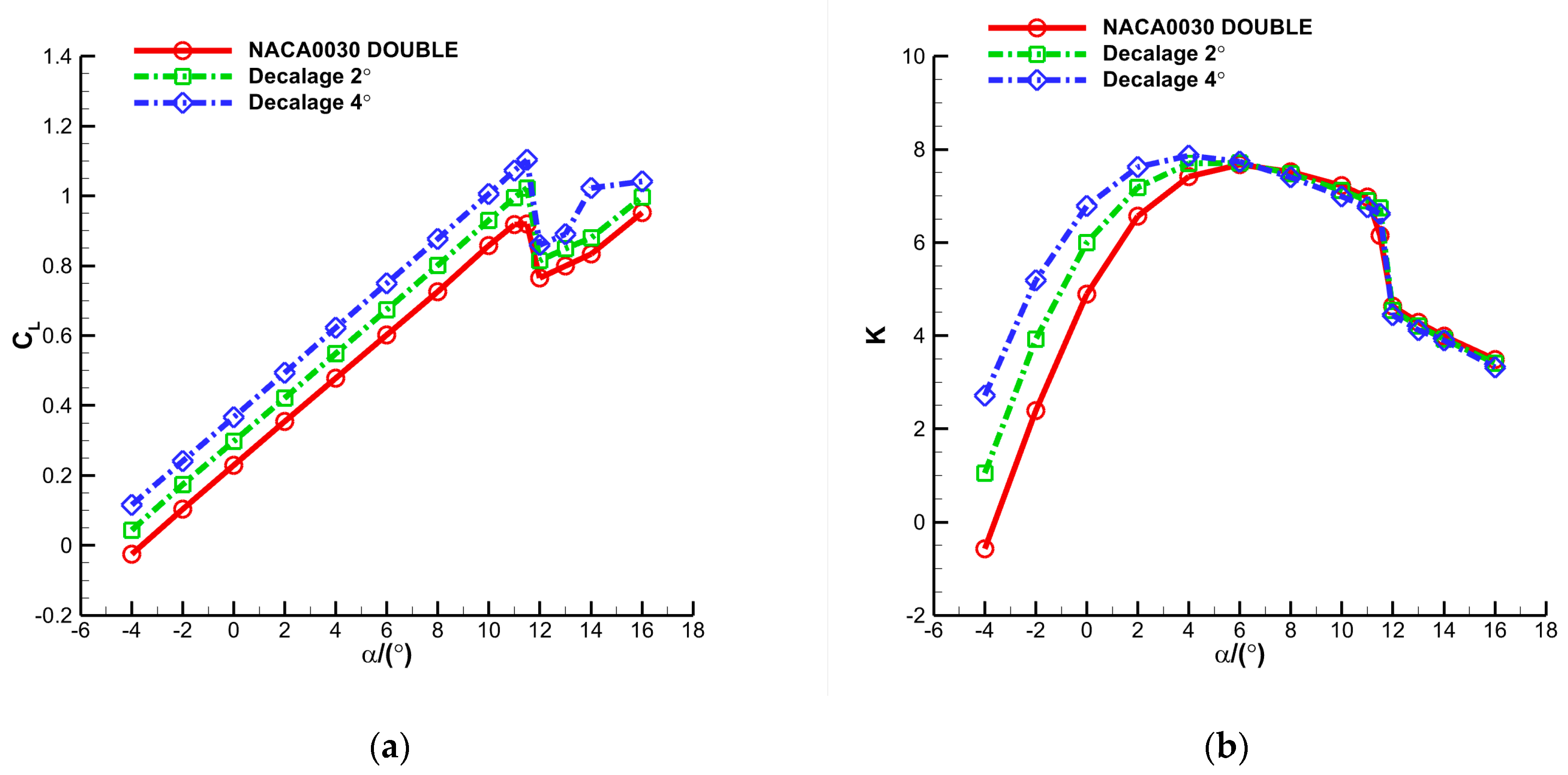
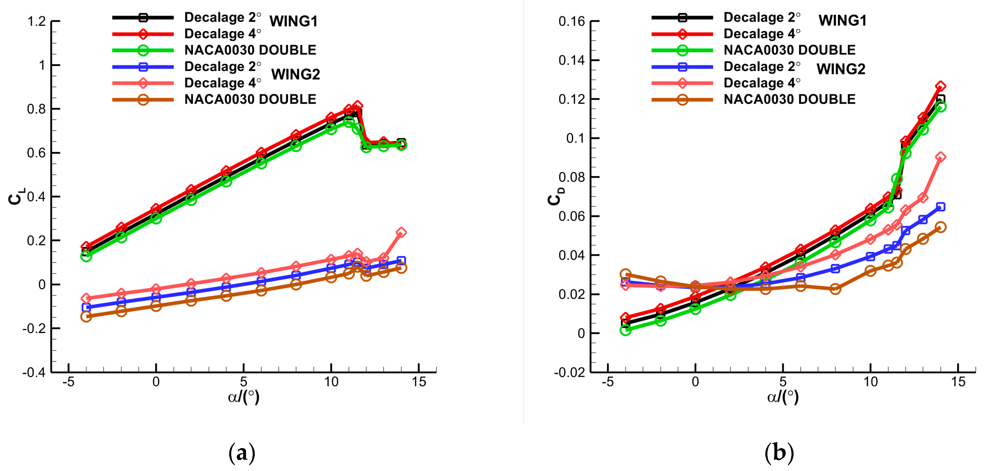
Figure 18 illustrates the computational comparisons of aerodynamic coefficients for configurations with hindwing decalage. As shown in the figure, the lift of configurations with hindwing decalage increase linearly with the increase in the angle of attack before stalling, but aerodynamic efficiency shows substantial increments only at angles of attack smaller than 4°.
In order to understand the effect of hindwing decalage on the overall characteristics of tandem configurations, lift and drag coefficients for every wing of the tandem configuration with 2° or 4°decalage are exhibited in
Figure 19. It shows that the lift increment increases with the increment of decalage, but it is more evident for the hindwing. In the meantime, the drag also increases with the increment of decalage.
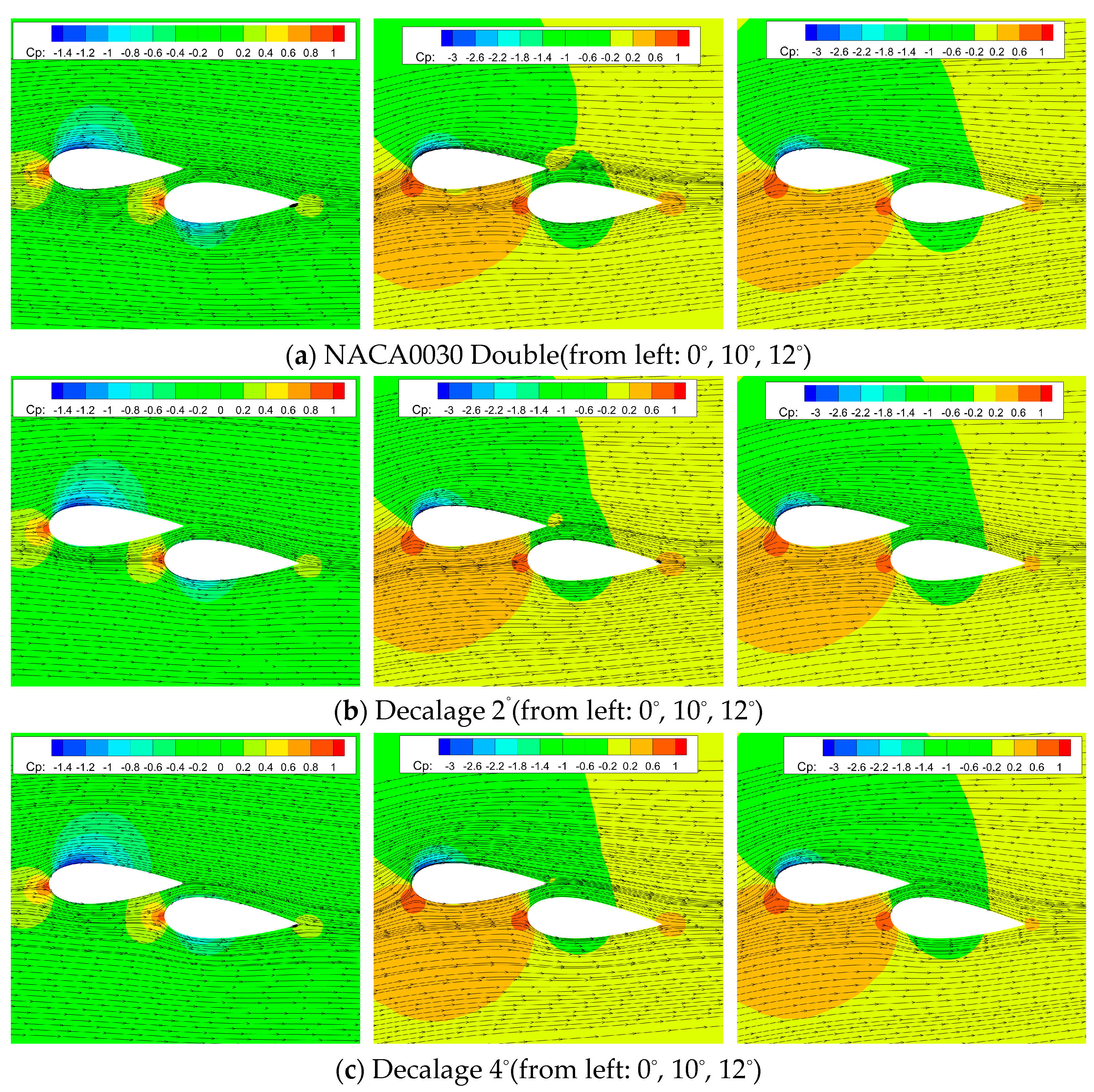
Figure 20 and
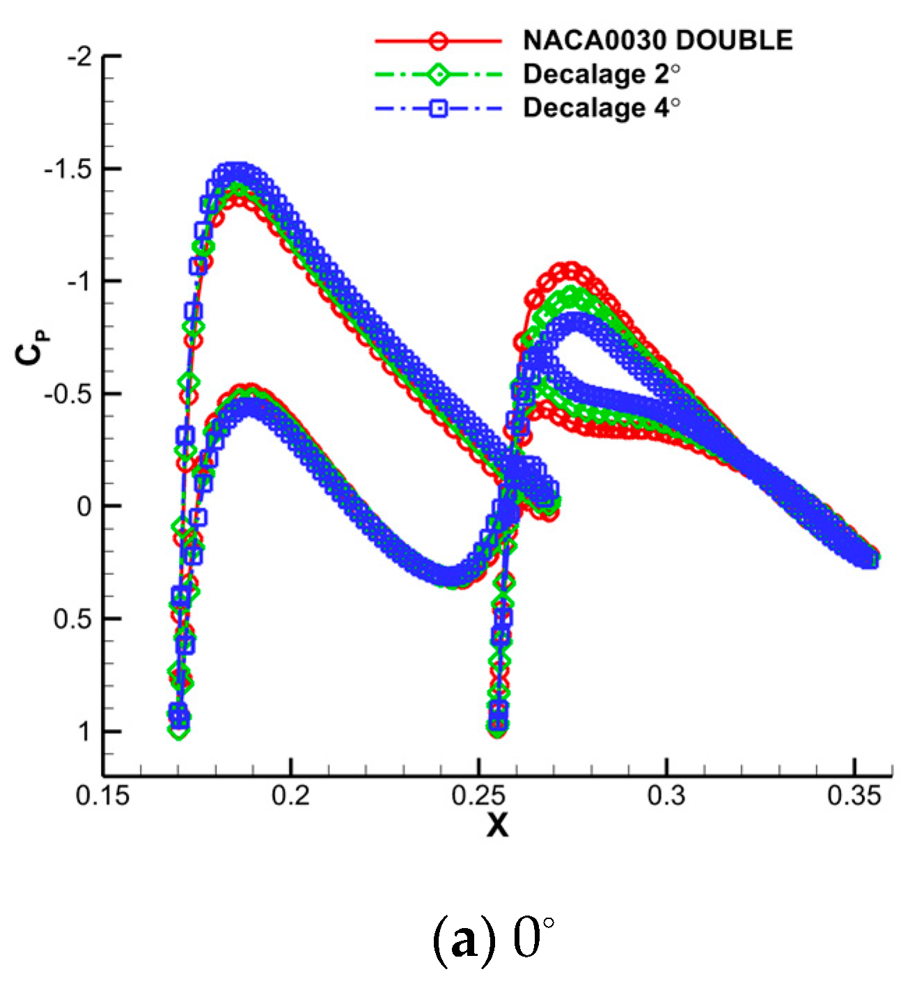
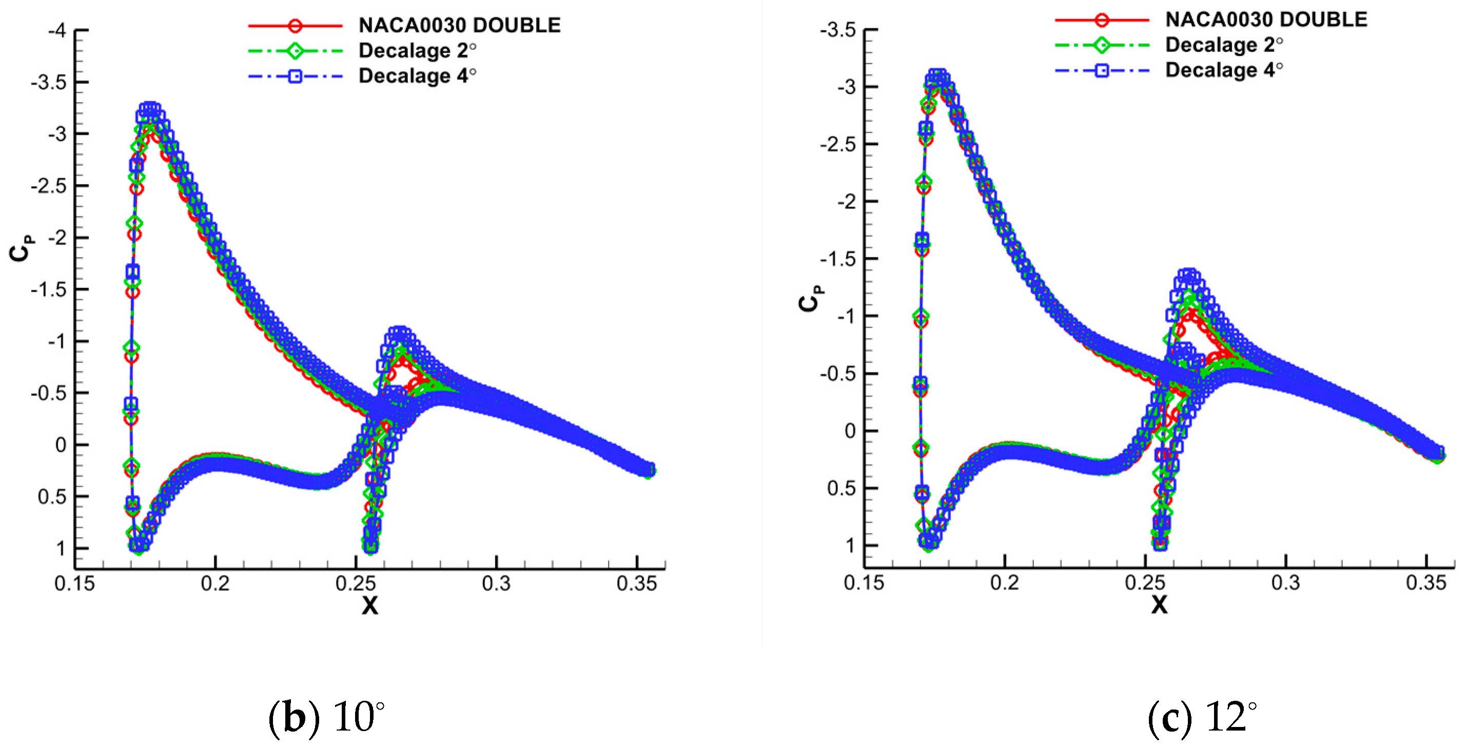
Figure 21 present the streamlines and the pressure distributions of the wing surface at 50% of the semispan at three typical angles of attack. At angle of attack 0°, the decalage will make the accelerating effect stronger, so there will be a clear decrement of pressure on the upper surface of the forewing. The lift at the upstream part of the hindwing will have a small decrease because of the blocking effect of the forewing, so the net lift will have an evident increment. At 10° and 12°, the forewing pressure will have little variation with the change of the decalage bacause the flow is about to stall. The net lift will drop, although the hindwing will have a little lift increase.
5. Concluding Remarks
In the present work, a detailed study of several tandem wing configurations was carried out numerically by our in-house coded F2M to investigate the aerodynamic characteristics of the novel configuration at low subsonic regime based on our experimental work in LTWT of NPU. After thorough analysis of these experimental and computational results, the following conclusions could be obtained:
(1) For the tandem configuration, the improvement of aerodynamic efficiency is more significant for wings with a thick airfoil than for wings with a thin profile. Compared to configuration with a single wing, the greatest percentage of aerodynamic efficiency improvement for a tandem thick configuration was as high as 1376% at angle of attack 0°. Even if the hindwing is deflected by a small angle about its quarter chord, the lift enhancement of the whole configuration is significant. It is generally attributed to the accelerating effect of the narrow gap between the two wings that blows the separated flow away. In addition, the high pressure at the standing area of the leading edge of the hindwing is an important origin of the lift enhancement of the forewing.
(2) For tandem wings with a corrugated surface, the stall characteristics could be improved because the waviness of the upper surface could lead the transition from laminar to turbulent further upstream than smooth surface, thus delaying the serious separation to a larger angle of attack and weakening the flow separation, which causes most of the loss of lift.
(3) For aerodynamic configurations with tandem wings, the lift will not drop as precipitously as conventional aircraft after stalling due to the compensatory effect of the hindwing, so they generally have a better stalling performance at large angles of attack.
(4) For MAVs, airships, or other flight platforms with inflatable structures, a tandem wing configuration is attractive and promising in the near future, after integrating optimization designs of efficient structural and aerodynamic efficiency.
Although the aerodynamic characteristics of several kinds of tandem wings were compared and the advantages were presented at very low subsonic speeds in our work, the effectiveness, efficiency and inherent control and stability of the configurations at lower density air and higher subsonic speeds remains to be demonstrated before tandem configuration could be applied extensively in the design of real MAVs.
Author Contributions
Q.Z.: Computational investigations, methodology, data analysis, writing—original draft, R.X.: writing—review and editing, funding acquisition, H.L.: writing—review and editing, funding acquisition. All authors have read and agreed to the published version of the manuscript.
Funding
This research was funded by the National Natural Science Foundation of China (Grant Nos.62175243, 12202331), Guangdong Basic and Applied Basic Research Foundation (Grant No.2021A1515110002), and Natural Science Basic Research Program of Shaanxi (Grant No.2022JQ−028).
Data Availability Statement
The datasets generated or analyzed during this study are available from the corresponding author on reasonable request.
Acknowledgments
The computational work was carried out in the Gekko Cluster in the High Performance Computing Centre in Nanyang Technological University, and the work in this paper could not be accomplished successfully without the technical support from the School of Mechanical & Aerospace Engineering, Nanyang Technological University.
Conflicts of Interest
The authors declare that they have no known competing financial interests or personal relationships that could have appeared to influence the work reported in this paper.
References
- Ellington, C.; Berg, C.; Willmott, A.; Thomas, A. Leading-edge vortices in insect flight. Nature 1996, 384, 626–630. [Google Scholar] [CrossRef]
- Dickinson, M.; Lehmann, F.; Sane, S. Wing rotation and the aerodynamic basis of insect flight. Science 1999, 284, 1954–1960. [Google Scholar] [CrossRef] [PubMed]
- Srygley, R.; Thomas, A.L.R. Unconventional lift-generating mechanisms in free-flying butterflies. Nature 2002, 420, 660–664. [Google Scholar] [CrossRef] [PubMed]
- Tong, B.; Lu, X. A review on biomechanics of animal flight and swimming. Adv. Mech. 2004, 34, 1–8. (In Chinese) [Google Scholar] [CrossRef]
- Taylor, G.; Nudds, R.; Thomas, A. Flying and swimming animals cruise at a Strouhal number tuned for high power efficiency. Nature 2003, 425, 707–710. [Google Scholar] [CrossRef]
- Shyy, W.; Aono, H.; Kang, C.; Liu, H. An Introduction to Flapping Wing Aerodynamics; Cambridge University Press: New York, NY, USA, 2013; ISBN 9781139583916. [Google Scholar] [CrossRef]
- Zhang, W.; Zhang, Y.; Chen, H.; Tang, Q. Main characteristics of suction control of flow separation of an airfoil at low Reynolds numbers. Eur. J. Mech. B/Fluids 2017, 65, 88–97. [Google Scholar] [CrossRef]
- Bartl, J.; Sagmo, K.; Bracchi, T.; Sætran, L. Performance of the NREL S826 airfoil at low to moderate Reynolds numbers-A reference experiment for CFD models. Eur. J. Mech. B/Fluids 2019, 75, 180–192. [Google Scholar] [CrossRef]
- Lian, Y.; Broering, T.; Hord, K.; Prater, R. The characterization of tandem and corrugated wings. Prog. Aerosp. Sci. 2014, 65, 41–69. [Google Scholar] [CrossRef]
- Tamai, M.; Wang, Z.; Rajagopalan, G.; Hu, H.; He, G. Aerodynamic performance of a corrugated dragonfly airfoil compared with smooth airfoils at low Reynolds numbers. In Proceedings of the 45th AIAA Aerospace Sciences Meeting and Exhibit, Reno, NV, USA, 8–11 January 2007. [Google Scholar] [CrossRef] [Green Version]
- Warkentin, J.; Delaurier, J. Experimental aerodynamic study of tandem flapping membrane wings. J. Aircr. 2007, 44, 1653–1661. [Google Scholar] [CrossRef] [Green Version]
- Scharpf, D.; Mueller, T. Experimental study of a low Reynolds number tandem airfoil configuration. J. Aircr. 1992, 29, 231–236. [Google Scholar] [CrossRef]
- Hua, R.; Ye, Z. Research on effective aerodynamic configuration of row inflatable wings. Acta Aerodyn. Sin. 2012, 32, 184–191. (In Chinese) [Google Scholar] [CrossRef]
- Zhan, H.; Bai, P.; Chen, Q.; Shi, Z. Experimental investigation on the aerodynamic characteristics of biplane micro-air-vehicles. J. Exp. Fluid Mech. 2009, 23, 24–30. (In Chinese) [Google Scholar] [CrossRef]
- Broering, T.; Lian, Y. Numerical study of tandem flapping wing aerodynamics in both two and three dimensions. Comput. Fluids 2005, 115, 124–139. [Google Scholar] [CrossRef]
- Broering, M.; Lian, S. The effect of phase angle and wing spacing on tandem flapping wings. Acta Aerodyn. Sin. 2012, 28, 1557–1571. [Google Scholar] [CrossRef]
- Broering, T.; Lian, S.; Henshaw, W. Numerical Investigation of energy extraction in a tandem flapping wing configuration. AIAA J. 2012, 50, 2295–2307. [Google Scholar] [CrossRef] [Green Version]
- Rival, D.; Hass, G.; Tropea, C.; Tropea, C. Recovery of energy from leading- and trailing-edge vortices in tandem-airfoil configurations. J. Aircr. 2012, 48, 203–211. [Google Scholar] [CrossRef] [Green Version]
- Luo, L.; Jiang, C.; Gao, Z.; Lee, C. Aerodynamic interference and Reynolds number effects of low-speed close-coupled biplanes. J. Aerosp. Eng. 2020, 33, 04020026. [Google Scholar] [CrossRef]
- Lim, K.; Tay, W. Numerical analysis of the s1020 airfoils in tandem under different flapping configurations. Acta Aerodyn. Sin. 2010, 26, 191–207. [Google Scholar] [CrossRef]
- Zhang, Q.; Ye, Z. Computational investigations for aerodynamic characteristic analysis of low Reynolds number doubly−tandem wing configurations. Eng. Mech. 2019, 36, 244–256. (In Chinese) [Google Scholar] [CrossRef]
- Li, F.; Ye, Z.; Gao, C. Design of a new tandem wings hybrid airship. Sci. China Phys. Mech. 2012, 55, 1886–1893. [Google Scholar] [CrossRef]
- Li, F.; Ye, Z.; Gao, C. Aerodynamic optimization design of new type tandem airship based on response surface methodology. Chin. J. Theor. Appl. Mech. 2011, 43, 1068–1076. (In Chinese) [Google Scholar] [CrossRef]
- Ren, H.; Wang, X.; Li, X.; Chen, Y. Effects of dragonfly wing structure on the dynamic performances. J. Bionic Eng. 2013, 10, 28–38. [Google Scholar] [CrossRef]
- Arjangpay, A.; Darvizeh, A.; Tooski, M. Effects of structural characteristics of a bionic dragonfly wing on its low velocity impact resistance. J. Bionic Eng. 2018, 15, 859–871. [Google Scholar] [CrossRef]
- Zhao, Y.; Wang, D.; Tong, J.; Sun, J. Nanomechanical behaviour of the membranous wings of dragonfly pantala flavescens fabricius. J. Bionic Eng. 2016, 13, 388–396. [Google Scholar] [CrossRef]
- Zhou, Y.; Wang, Z. Effects of surface roughness on separated and transitional flows over a wing. AIAA J. 2012, 50, 593–609. [Google Scholar] [CrossRef]
- Wang, X.; Zhang, Z.; Ren, H.; Chen, Y.; Wu, B. Role of soft matter in the sandwich vein of dragonfly wing in its configuration and aerodynamic behaviors. J. Bionic Eng. 2017, 14, 557–566. [Google Scholar] [CrossRef]
- Xiang, J.; Du, J.; Li, D.; Liu, K. Aerodynamic performance of the locust wing in gliding mode at low Reynolds number. J. Bionic Eng. 2016, 13, 249–260. [Google Scholar] [CrossRef]
- Zhang, S.; Ochiai, M.; Sunami, Y.; Hashimoto, H. Influence of microstructures on aerodynamic characteristics for dragonfly wing in gliding flight. J. Bionic Eng. 2019, 16, 423–431. [Google Scholar] [CrossRef]
- Rees, C. Aerodynamic properties of an insect wing section and a smooth aerofoil compared. Nature 1975, 258, 141–142. [Google Scholar] [CrossRef]
- Meng, X.; Sun, M. Aerodynamic effects of corrugation in flapping insect wings in forward flight. J. Bionic Eng. 2011, 8, 140–150. [Google Scholar] [CrossRef]
- Le, T.; Truong, T.; Tran, H.; Park, S. Two-and three-dimensional simulations of beetle hind wing flapping during free forward flight. J. Bionic Eng. 2013, 10, 316–328. [Google Scholar] [CrossRef]
- Lian, Y.; Shyy, W. Laminar-turbulent transition of a low Reynolds number rigid or flexible airfoil. AIAA J. 2007, 45, 1501–1513. [Google Scholar] [CrossRef] [Green Version]
- Hua, R.; Zhao, C.; Ye, Z.; Jiang, Y. Effect of elastic deformation on the trajectory of aerial separation. Aerosp. Sci. Technol. 2015, 45, 128–139. [Google Scholar] [CrossRef]
- Hua, R.; Ye, Z.; Wu, J. Effects of rotational motion on dynamic aeroelasticity of flexible spinning missile with large slenderness ratio. Aerosp. Sci. Technol. 2017, 71, 347–359. [Google Scholar] [CrossRef]
- Li, H.; Ye, Z. Effects of rotational motion on dynamic aeroelasticity of flexible spinning missile with large slenderness ratio. Aerosp. Sci. Technol. 2019, 94, 105384. [Google Scholar] [CrossRef]
- Li, H.; Ye, Z. Numerical investigation on aerodynamic and inertial couplings of flexible spinning missile with large slenderness ratio. Aerosp. Sci. Technol. 2020, 99, 105582. [Google Scholar] [CrossRef]
- Zhang, M.; Wang, G.; Xu, J. Aerodynamic control of low-Reynolds-number airfoil with leading-edge protuberances. AIAA J. 2013, 51, 1960–1971. [Google Scholar] [CrossRef]
- Zhang, Q.; Xue, R. Aerodynamic exploration of corrugated airfoil based on NACA0030 for inflatable wing structure. Aerospace 2023, 10, 174. [Google Scholar] [CrossRef]
Figure 1.
Tandem (left) and corrugated (right) wing configurations of a natural dragonfly.
Figure 1.
Tandem (left) and corrugated (right) wing configurations of a natural dragonfly.
Figure 2.
Definition of gap (△z)and stagger (△x) for tandem wing configuration.
Figure 2.
Definition of gap (△z)and stagger (△x) for tandem wing configuration.
Figure 3.
Experimental model fixed in the wind tunnel in NPU.
Figure 3.
Experimental model fixed in the wind tunnel in NPU.
Figure 4.
Experimental wings with varied gap and stagger.
Figure 4.
Experimental wings with varied gap and stagger.
Figure 5.
Three views of the experimental model.
Figure 5.
Three views of the experimental model.
Figure 6.
Sketch of the wavy airfoil and original NACA 0030 airfoil.
Figure 6.
Sketch of the wavy airfoil and original NACA 0030 airfoil.
Figure 7.
Comparison of pressure coefficients for SD 7003 at angle of attack 4° by various numerical methods.
Figure 7.
Comparison of pressure coefficients for SD 7003 at angle of attack 4° by various numerical methods.
Figure 8.
Comparison of pressure distribution for various grids with different first-layer thickness at angle of attack 8°.
Figure 8.
Comparison of pressure distribution for various grids with different first-layer thickness at angle of attack 8°.
Figure 9.
Computational grid distribution at different positions (a) Farfield; (b) surface of the airframe (without endplates); (c) surface of the tandem wing (NACA0030); and (d) surface of the tandem wavy wing.
Figure 9.
Computational grid distribution at different positions (a) Farfield; (b) surface of the airframe (without endplates); (c) surface of the tandem wing (NACA0030); and (d) surface of the tandem wavy wing.
Figure 10.
Time averaged aerodynamic coefficients for models with different thickness: (a) lift coefficient; and (b) ratio of lift to drag.
Figure 10.
Time averaged aerodynamic coefficients for models with different thickness: (a) lift coefficient; and (b) ratio of lift to drag.
Figure 11.
Time averaged aerodynamic coefficients for models with different thickness: (a) lift coefficient; and (b) drag coefficient.
Figure 11.
Time averaged aerodynamic coefficients for models with different thickness: (a) lift coefficient; and (b) drag coefficient.
Figure 12.
Streamlines of the mid-semispan plane at different angles of attack.
Figure 12.
Streamlines of the mid-semispan plane at different angles of attack.
Figure 13.
Comparisons of wall pressure coefficient of mid-semispan at different angle of attack.
Figure 13.
Comparisons of wall pressure coefficient of mid-semispan at different angle of attack.
Figure 14.
Time averaged aerodynamic coefficients for models with smooth/wavy wing: (a) lift coefficient; and (b) ratio of lift to drag.
Figure 14.
Time averaged aerodynamic coefficients for models with smooth/wavy wing: (a) lift coefficient; and (b) ratio of lift to drag.
Figure 15.
Time averaged aerodynamic coefficients for models with smooth/wavy wing: (a) lift coefficient; and (b) drag coefficient.
Figure 15.
Time averaged aerodynamic coefficients for models with smooth/wavy wing: (a) lift coefficient; and (b) drag coefficient.
Figure 16.
Streamlines of mid-semispan plane at different angle of attack.
Figure 16.
Streamlines of mid-semispan plane at different angle of attack.
Figure 17.
Comparisons of wall pressure coefficient of mid-semispan at different angle of attack.
Figure 17.
Comparisons of wall pressure coefficient of mid-semispan at different angle of attack.
Figure 18.
Time averaged aerodynamic coefficients for models with hindwing decalage (a) lift coefficient; and (b) ratio of lift to drag.
Figure 18.
Time averaged aerodynamic coefficients for models with hindwing decalage (a) lift coefficient; and (b) ratio of lift to drag.
Figure 19.
Aerodynamic coefficients for models with hindwing decalage: (a) lift coefficient; and (b) drag coefficient.
Figure 19.
Aerodynamic coefficients for models with hindwing decalage: (a) lift coefficient; and (b) drag coefficient.
Figure 20.
Streamlines of mid-semispan plane at different angle of attack.
Figure 20.
Streamlines of mid-semispan plane at different angle of attack.
Figure 21.
Comparisons of the wall pressure coefficient of mid-semispan at different angle of attack.
Figure 21.
Comparisons of the wall pressure coefficient of mid-semispan at different angle of attack.
Table 1.
Comparison of lift and drag coefficients by different computational methods.
Table 1.
Comparison of lift and drag coefficients by different computational methods.
| Method | CL (Relative Error) | CD (Relative Error) |
|---|
| Ref. [33] | 0.561 | 0.021 |
| inviscid | 0.6541 (16.60%) | 0.0025 (−88.10%) |
| S—A | 0.5561 (−0.87%) | 0.0219 (4.29%) |
| γ-Reθ transition | 0.5654 (0.78%) | 0.0223 (6.19%) |
| Disclaimer/Publisher’s Note: The statements, opinions and data contained in all publications are solely those of the individual author(s) and contributor(s) and not of MDPI and/or the editor(s). MDPI and/or the editor(s) disclaim responsibility for any injury to people or property resulting from any ideas, methods, instructions or products referred to in the content. |
© 2023 by the authors. Licensee MDPI, Basel, Switzerland. This article is an open access article distributed under the terms and conditions of the Creative Commons Attribution (CC BY) license (https://creativecommons.org/licenses/by/4.0/).


