1. Introduction
Different projects from Airbus [
1], Boeing, and NASA [
2], indicate that flying wings are one of the most promising concepts for the future of commercial aviation, mainly due to their significant aerodynamic efficiency, which is about 20 percent higher than conventional aircraft [
3], and, hence, fuel savings and much lower pollution [
4]. Moreover, flying wings have other advantages [
5], including greater internal volume, aerodynamics and structural efficiency, noise reduction, and a significant improvement in cost per seat-mile [
2].
This work aims to develop and test an algorithm to optimize the drag and weight of a tailless aircraft to assist the preliminary design process and employ it in a study case to evaluate insights. A Multidisciplinary Design Optimization (MDO) is employed to optimize the flying-wing geometry and its main I-shaped beam, while longitudinal static stability is assured. Hence, the structure of the wing is simplified to a main beam [
6], and the aerodynamic shape is the flying-wing itself. These two simplified approaches are enough, given that the article studies the preliminary design approach. The study case focuses on the lower end of the transonic regime, about Mach number
.
The wing geometry is parameterized essentially by the aspect ratio, tip to chord ratio, wing incidence, aerodynamic twist angle, sweep angle, and airfoil shape distribution. Throughout the optimization, each candidate wing is assessed using the Athena Vortex Lattice (AVL) method, given its low computational cost compared to other more robust methods, such as Computational Fluid Dynamics (CFD) [
7]. Since inviscid potential methods have shown similar results only for the lift coefficient in comparison against CFD [
8], AVL is employed for lift and stability analysis. However, the AVL is based on an extended Vortex Lattice Method (VLM) which considers the induced drag only, and, therefore, XFOIL (a panel-based algorithm coupled with an integral boundary layer formulation) is employed to estimate the skin and pressure drag, namely the parasitic drag.
The airfoil parameterization method selection aims at a low number of parameters to reduce the computational cost and enable generation of reflex airfoils, which improves the stability of tailless aircraft [
2,
9,
10]. Although other optimizations of tailless aircraft have employed Bezier curves [
11], a six parameters method [
12] is implemented. The longitudinal stability of tailless aircraft can be obtained using a reflex airfoil or by using sweep and twist wings [
9], but, due to modified pressure distribution over a reflex airfoil, the produced lift is less, compared to conventional airfoil, and the drag higher [
13]. Hence, this work assesses what method of fulfilling stability in flying wings is more suitable.
The forces from AVL and XFOIL are the inputs for the structural module, where a Finite Element Analysis (FEA) is carried out. The von Mises stress with a safety factor is compared against the tensile yield strength of the beam material, which must be assumed isotropic. The aerodynamic module is fed into a two-way coupling by the vertical beam displacement as a dihedral distribution until it converges. Moreover, a penalty function is applied when the structural criterion is not fulfilled or when the longitudinal static stability criteria are not accomplished. The Particle Swarm Optimization (PSO) is employed to solve the constraint of the multi-objective, MDO, problem due to the fact it has been reported to be faster than other algorithms, such as generic algorithms or sine–cosine optimizers [
14,
15].
Recent studies have assessed wing optimization using XFOIL, CFD and non-linear lifting line methods without stability constraints [
16]. Similarly, a stability-constrained aerodynamic optimization of flying wings has been assessed [
10]. However, in both studies, the structural analysis was restricted to keeping a root bending moment constraint, which does not allow interaction between aerodynamics and structural deflection. Moreover, the assumption implicit in the approaches was that two wings with the same root bending moment have the same weight. Other works have evaluated a fully coupled aero-structural optimization using FEA and CFD [
7], having a high computational cost, without considering stability constraints, and applied to conventional aircraft.
This research seeks to expand and contribute in different ways. First, it develops a two-way coupled aero-structural optimization algorithm to optimize the preliminary design of tailless aircraft. Based on this algorithm, conclusions about the feasibility of the finite element analysis are reached in terms of computational cost as the structural constraint, instead of using a root moment restriction. Finally, the optimal wing geometry of a tailless aircraft is studied and compared against the literature results, including how the aerodynamics and structures impact the different wing parameters.
Moreover, a study case is carried out to compare the results of the algorithm developed against a baseline optimization in the literature [
9]. Other studies have stated that an elliptical lift distribution is achieved by non-constant twist (a piecewise function) [
10,
17] and that a positive static margin for tailless aircraft is hard to achieve, sometimes requiring the sacrifice of the elliptic lift distribution [
2,
10,
11]. In contrast, the optimal aircraft found in the study case has a considerably high static margin and an almost elliptical lift distribution with a constant geometric twist -linear-.
2. Aerodynamic Modeling
During the optimization process, each candidate flying wing is analyzed under a static condition at the design point, usually cruise condition. First, the lift force is estimated by AVL, which is employed to find the equilibrium angle at which lift is equal to the weight and there is a zero total moment about the gravity center. Inviscid potential methods have shown similar results in comparison against CFD [
8], especially for lift coefficient before stall. However, AVL methodology cannot estimate the parasitic drag and so XFOIL is employed to estimate it. Hence, each candidate wing geometry, including aerodynamic and geometric twist, is evaluated in AVL and XFOIL.
2.1. Airfoil Parameterization
There is a large set of airfoil parameterization methods. However, the best trade-off between low computational cost and the design space size must be considered. For instance, although the four digits NACA parameterization is able to produce a wide range of airfoil shapes with high aerodynamic efficiency with just three parameters [
14], it is unable to produce reflex airfoils. Another standard parameterization that can produce reflex airfoils is the Bezier curve parameterization [
11], which employs 12 parameters.
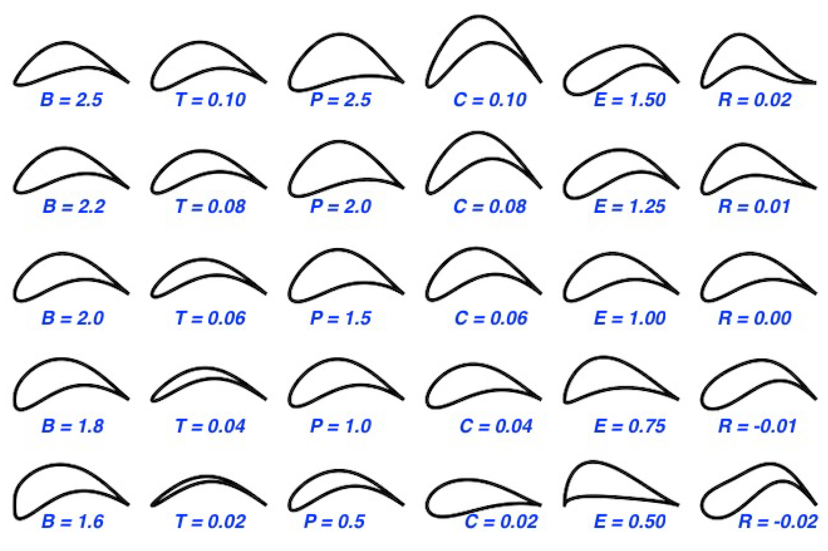
It is known that reflex airfoils can improve the stability of tailless aircraft [
2,
9,
10], hence a six parameter method, [
12] able to produce reflex airfoils, was selected, as seen in
Figure 1. The Equations (
1) and (
2) are employed to get the airfoil coordinates, where
.
2.2. AVL
AVL is based on VLM, which calculates lift curve slope, induced drag and lift distribution for the given wing. The modeling is performed by some elements that produce lift, called horseshoe vortices, distributed along span and chord. The airflow effect on the wing is estimated mainly using the Biot–Savart Law, the Kutta–Joukovsky theorem, the Hermann von Helmholtz theory, and the Prandtl lifting-line theory.
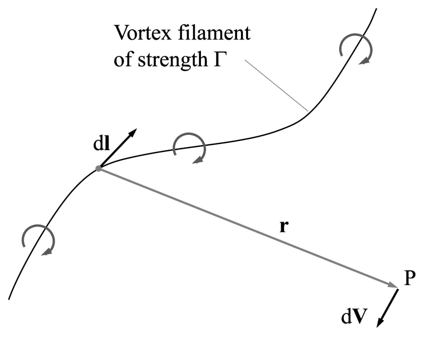
A vortex filament
induces a flow field in the surrounding space (
Figure 2), estimated by the Biot–Savart Law (Equation (
3)) [
18], being Γ the strength of the vortex. This strength or circulation produces lift according to the Kutta–Joukovsky theorem (Equation (
4)).
The Hermann von Helmholtz theory establishes that the vortex filament must be closed and its circulation constant. The closed vortex is modeled by four vortex filaments using the Prandtl lifting-line theory. Finally, the wing is divided into panels and a horseshoe vortex is located at each panel. A sample is shown in
Figure 3. The total force is obtained by the sum of each panel contribution.
Since the flow is potential (linear aerodynamic), the main limitations of the methodology are the stall prediction, compressibility impact, and the fact that only induced drag can be estimated. To complete the aircraft drag, XFOIL is employed to account for the skin and pressure friction. The compressibility impact is taken into account by the subsonic Prandtl–Glauert Equation (
5); the same equation is employed to correct the drag.
2.3. XFOIL
XFOIL is a computational implementation of the panel method coupled to an integral boundary layer formulation and a
laminar to turbulent transition technique [
19]. This tool allows predicting
and
at small angles of attack, preferably before stall. In case of divergence, a recursion within the code is applied, increasing the nodes over the top and bottom surfaces of the airfoil. The initial setup is defined with 150 maximum iterations and 200 nodes over the airfoil surface, and a smoothing step, to avoid any high variation of the coordinates, is also applied.
Compressibility Correction
The Karman–Tsien correction [
20,
21] is employed to consider the Mach effect. The drag coefficient correction is shown in Equation (
6), which is also valid for the lift coefficient.
2.4. Reynolds Corrections
Despite the recursivity implemented, some airfoils occasionally do not converge. In these cases, the same airfoil is simulated at a higher Reynolds number, which usually helps in convergence, and some corrections are implemented to take this into account. The first is a drag correction [
22] through Equation (
7). On the other hand, the lift slope is not highly affected by the Reynolds number, but the stall angle is. The Equation (
8) is employed to estimate this impact [
23].
3. Structural Modeling
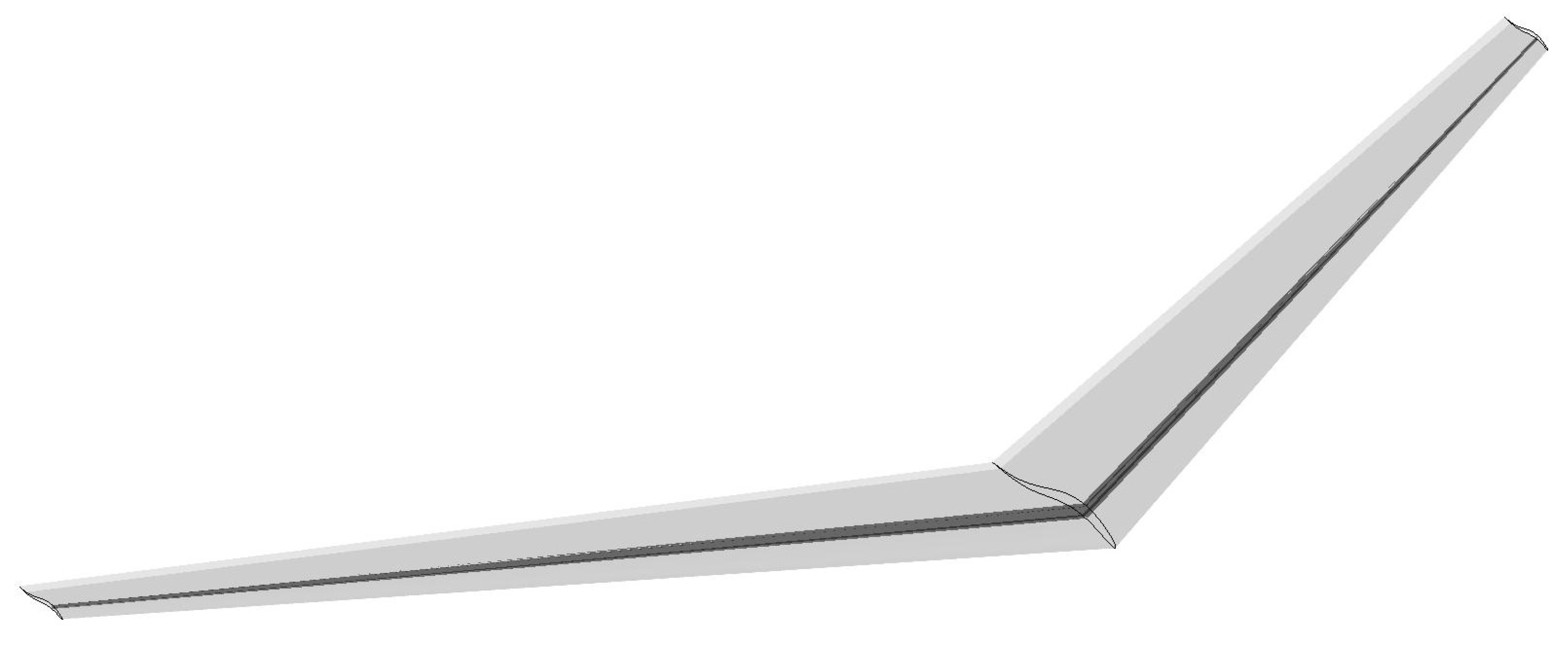
The flying-wing structure is modeled by an I-shaped main beam centered at the wing’s quarter chord, as shown in
Figure 4. The beam is located by considering the wing incidence and the equilibrium angle at the design point, which means the I beam is straight at the flight condition. The beam has two parameters, the height of the beam at the tip and at the root. These values are estimated from the wing geometry at these stations in order to keep the beam within the boundaries of the airfoil, and the sections between tip and root are linearly interpolated. The other beam parameters are estimated from the beam height using the relations employed in [
6], Equations (
9)–(
11).
Mesh and Boundary Conditions
The mesh for the FEA is composed of tetrahedral elements and is described by a quadratic element order, where each element has ten nodes, each at its corners and edge centers. The maximum mesh edge length is restricted to
, and the mesh growth rate is set to
. Moreover, the mesh is further refined at the root (see
Figure 5), where the stress increases rapidly. In the first lateral web and flange faces, the target edge size is calculated as
, and
on the clamped face.
The beam is centered at the quarter chord, where the aerodynamic forces are assumed. The clamped beam has the first face fixed, and the lift and drag forces are applied along the beam according to the load distribution from the aerodynamic method.
4. Optimization Algorithm
This optimization problem aims to reduce the total drag coefficient and the weight of the aircraft structure by decreasing the beam mass K while fulfilling the target lift at the equilibrium angle, the structural constraint via the yield strength, and the longitudinal static stability criteria, namely a zero pitch moment at the gravity center and the negative slope of the moment coefficient against the angle of attack. The routines have penalty functions to make the candidates move away from the zones where the constraints are not accomplished. Penalties are applied when structural safety is not fulfilled and when the slope of the moment coefficient against the angle of attack is not negative.
The optimization space is generated from 18 variables: the wing aspect ratio, the tip to root chord ratio, the angle of incidence, the geometric twist angle, the sweep angle, the airfoil parameters
B,
T,
P,
C,
E,
R for tip and root, and the position of the airfoil transition. The latter parameter refers to the place, in percentage, at which the airfoil changes from the root to the tip shape. The problem is as follows.
The objective function, where the aerodynamic and structural algorithms run, is optimized by a particle swarm algorithm, where a first random set of solutions is created, and then they move through the design space, being attracted to the best solution found by any particle and the best solution of their own particle history until they converge.
Figure 6 shows the general scheme of the optimization. Once the first candidate generation is created, each flying-wing is analyzed in AVL, where the angle at which the lift is equal to the weight is found, and recursion to find the gravity center position, to make the pitching moment zero, is employed. Next, the slope of the moment coefficient against the angle of attack is evaluated, and if its value is negative, the skin and pressure drag are estimated from XFOIL and added to the induced drag by AVL and, then, the structural model runs. Next, the beam is generated and analyzed via the finite element method, as described in the structural modeling section, where the structural safety is evaluated. If the structural constraint is fulfilled, the displacement in the vertical axis is employed as a dihedral angle distribution for AVL in a recursive algorithm until the structural loads and displacements converge with the aerodynamic forces and constraints with dihedral angle distribution. The displacement in the drag direction is neglected. Finally, the beam mass and the total drag coefficient turn into the fitness value for the optimization algorithm, with a penalty if any constraint is not fulfilled. This routine runs until the particle swarm ends.
The optimization algorithm searches the optimum within lower and upper boundaries for each design variable. These limits are: , , , , , , , , , , , . The boundaries for the airfoil parameters are the same for root and tip.
5. Case Study
To evaluate the algorithm and results, a case study was carried out. The same aerodynamic requirements and flight conditions (ISA 45000 ft) from another work [
9], were employed for the optimization, as siin in
Table 1. In addition, the aluminum alloy 7055-T77 was assumed for the main beam [
24] and a structural safety factor of
, regarding the load factor allowed for this kind of aircraft in the Federal Acquisition Regulation part 25.
5.1. Results
The optimum values for the study case are shown in
Table 2. These values achieved a minimum of 46.467, where the total drag coefficient was
, and the beam mass was
kg. The optimal wing with the beam is shown in
Figure 7.
The computational cost would vary drastically for different numbers of sections, FEA mesh parameters, and the size of the model. In this case study, a set up with a single Intel Core i7 8th generation and 32 GB of RAM was employed. For this set up, a single wing aerodynamic evaluation lasted about 3 s. When the stability criteria were met and the structural module ran, the wing evaluation lasted about 40 s, without considering the recursivity between the structural deflection and the updated wing geometry, which would depend on how much the wing was deflected.
The total PSO cost with 700 initial particles and 30 iterations was about 68 processor hours. The total time would be drastically decreased if a parallel strategy was applied. Many of the 700 initial particles did not fulfil the stability requirements, hence they ran in about 3 s. The high number of initial particles is required to have enough candidates that meet the stability criteria, to evolve in the subsequent iterations to the global optimal. Other similar studies have reported computing time for each function evaluation in the order of 10 min [
25,
26]. Higher order models have reported a single function evaluation cost for aero-structural wing optimization of around 1 h [
27].
5.1.1. Wing Geometry
The optimum wing aspect ratio was
, in comparison to the value of 6 estimated in the baseline study [
9], a study that did not consider structural modeling. However, other studies have shown optimal values of about 12 for metallic structures [
28], where a multi-objective optimization was carried out to minimize fuel consumption and weight using CFD. This value also coincides with the aspect ratio of the blended wing body for subsonic transport of Boeing [
2]. Hence the aspect ratio is a variable highly influenced by the interaction between the aerodynamic and structural optimizations.
The taper ratio of
was in agreement with the results of optimizing a wing without twist using lifting line theory and using an airfoil with lift slope of
, a study which showed an optimum value of about
without structural considerations [
29], and which had different optimization criteria and more restricted variables of wing aspect ratio and taper ratio. This value was similar to the baseline study results, where a taper ratio of
was employed for the inboard wing and
for the outboard wing. It suggests that the optimal root-to-tip ratio is not highly influenced by the structures but by the aerodynamics. The wing incidence reached the upper limit of 6° with a geometric twist of
°. Other studies have dealt with non-constant geometric twist [
10,
17], and the baseline estimated an optimum twist of
°.
The sweep angle at the quarter chord obtained for the study case was 27°, in comparison to the 30° of the outboard wing and
° for the inboard wing of the baseline study. The neutral point of the aircraft is altered primarily by changing the sweep of the wing [
10], and, then, this angle is highly affected by the aerodynamics. Moreover, the Mach number normal to the leading edge of the wing is reduced by sweep [
17]. The Mach was reduced to 0.757 in our case study (Equation (
12)), eliminating the shock wave and the corresponding drag [
10]. On the other hand, the effective bending moment is not necessarily aligned with the wing, and the torsional and bending component increases with the sweep [
10]. Other tailless aircraft reported different sweeps for leading and trailing edges with a mean sweep of
° [
17], which was also in agreement with the optimal range between 20° and 40° found in [
30] for tailless aircraft. These results suggest that the sweep angle was mainly influenced by the aerodynamics but with a restriction by the structures.
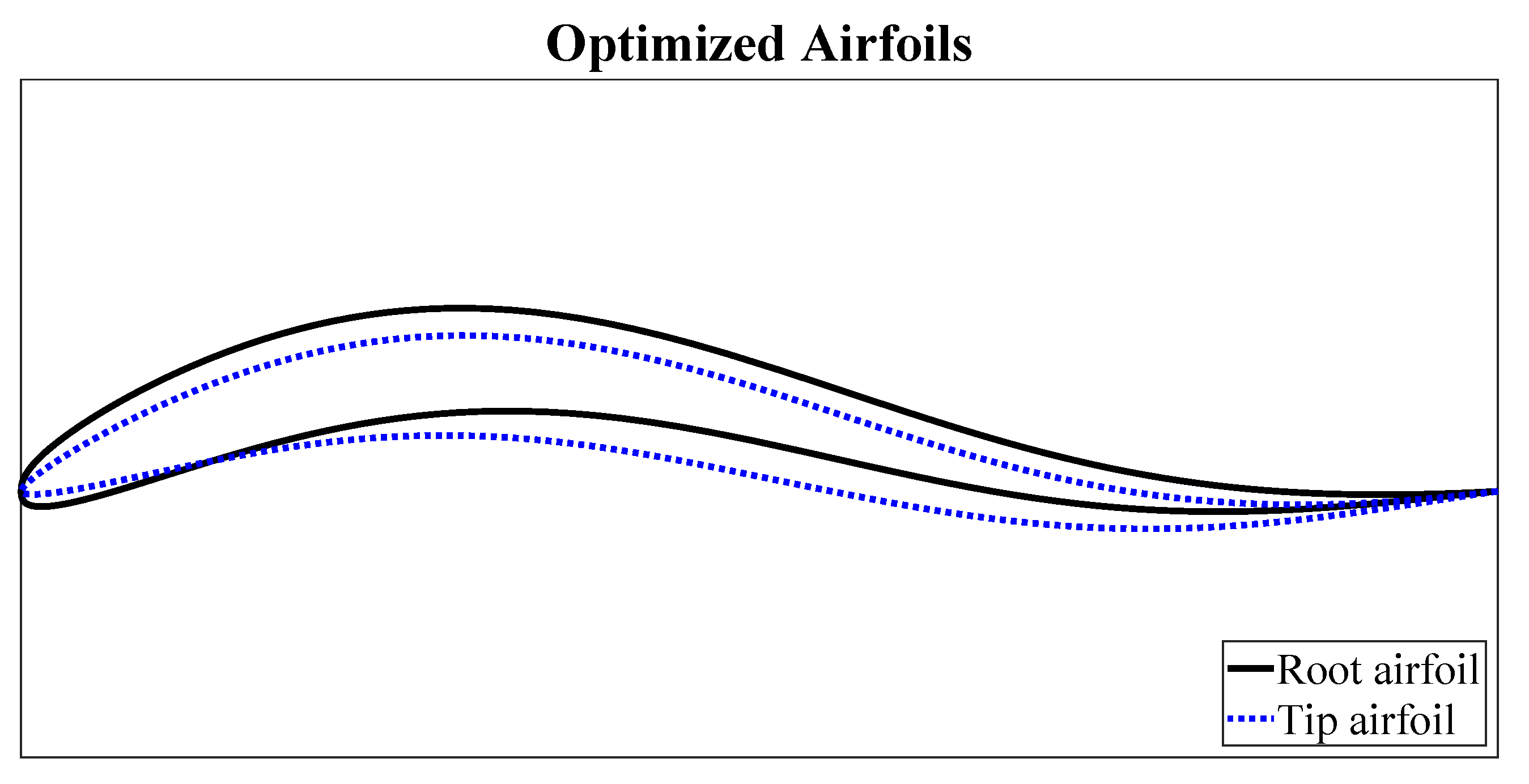
The aerodynamic twist is defined by three stations along the wing, the root, tip, and the transition section, which varied from 10% to 90%. The optimal value was obtained at 85%. The latter means that the wing has two different airfoils along the span-wise direction. The root and tip airfoil are defined by six parameters each, shown in
Table 2, and the shapes are shown in
Figure 8.
5.1.2. Airfoil Distribution
It is known that in order to accommodate passengers, cargo, and landing gear, the tailless aircraft requires inboard airfoils of a large thickness-to-chord ratio, about 17% [
11]. However, these considerations are out of the scope of this work, and part of future work. The thickness distribution is only affected by aerodynamics and structures. The airfoil’s thickness increases towards the wing’s root to better withstand the larger bending moments. The latter means that the larger the thickness, the higher the beam, so more inertia can be used. This behavior is present in other similar studies [
31].
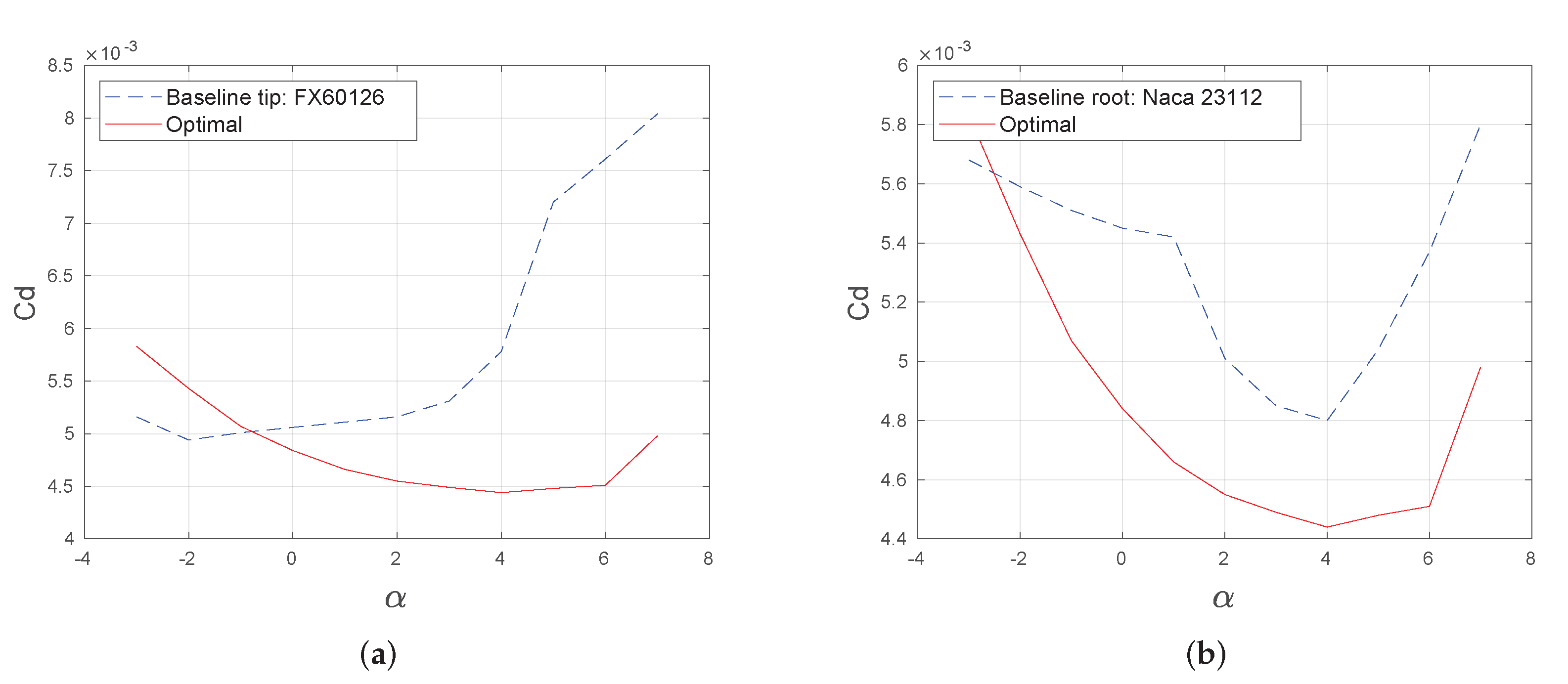
The baseline study employed the Wortmann FX 60-126 airfoil for the outboard wing with a maximum thickness of 12.6% and camber of 3.6%, and the NACA 23112 for the inboard wing with a maximum thickness of 12% and camber of 1.2%. The airfoils were optimized at 10.2% of maximum thickness and 6% of maximum camber at root and 9.7% of maximum thickness and 4% of maximum camber at the tip. The main differences were that the thickness of the baseline study was higher because of the constraints of volume, and the camber of the optimized airfoils was higher. Lower thickness of airfoils also reduces the effective Mach number, a similar effect to the sweep angle [
32], reducing shock waves and drag. The thickness values did not reach the boundaries. On the other hand, the camber for the tip airfoil reached the upper limit.
The airfoil and angle of attack distribution achieved remarkable aerodynamic characteristics compared to the baseline results, as summarized in
Table 3. The lift-to-drag ratio and the drag plots are also shown in
Figure 9 and
Figure 10. The parasitic drag was about the induced drag, which suggests that the optimization aimed to design the aircraft in such a way that the cruise condition was near the velocity of minimum drag, where induced and parasitic drag are equal. The parasitic drag of the optimized aircraft was about half of the baseline, while the span efficiency
e was almost equal. However, the aspect ratio of the optimized wing was greater, which made the induced drag considerably lower. Regarding the lift-to-chord ratio, the proposed aero-structural optimization achieved more than twice the baseline aerodynamic efficiency. This distribution is shown in
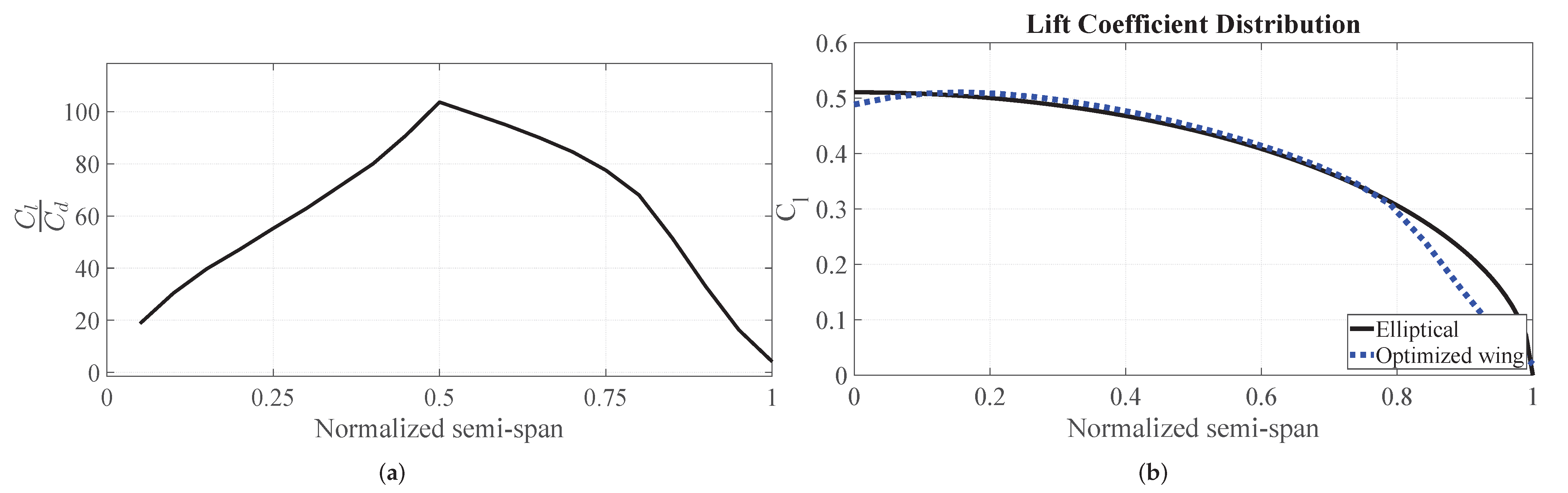
Figure 11a, where the peak was in the middle of the semi-span. One reason is that the airfoils (shape and twist) towards the tip have a meaningful stability impact, and the airfoils towards the root have a more significant impact on structure (a higher thickness is required for the beam), being the middle where the airfoil shape is influenced mainly by the aerodynamic efficiency.
The reflex values for both airfoils reached the lower boundary, which was different from other studies where the reflex increased towards the tip, reducing the local lift and, thus, minimizing the induced drag [
31]. This objective of minimizing induced drag was made by the geometric twist. The lift coefficient distribution of the optimized wing was almost the same elliptical distribution because it was the optimal distribution in induced drag, as seen in
Figure 11. The tendency change near the 80% of the semi-span was due to the change in the airfoil. These results suggest that the twist is the best way to get the optimal induced drag distribution, and the parasitic drag should be minimized by the airfoil shape itself in terms of camber and thickness.
5.1.3. Wing Structure
The structural constraint was fulfilled by the optimal, where the
MPa and the
MPa. The mesh had
nodes. The von Mises distribution along the semi-span is shown in
Figure 12a and the vertical displacement in
Figure 12b. The heat map of the von Mises stress at the clamped root is shown in
Figure 13. The maximum von Mises stress was at the top-left of the clamped face where the compressive stress caused by drag added to the compressive stress by lift and at the bottom-right where the tension from lift added to the tension of drag. In other locations, the compressive and tension stress had destructive interference.
5.1.4. Wing Stability
The stability criteria in the optimization routine involve the zero pitching moment by moving the gravity center, and then checking the negative sign of the slope of the total moment about this gravity center against the angle of attack. The gravity center of the optimal was at 89.30% of the root chord, which was 10.90 m. The neutral point was at 12.35 m, with a static margin of 16.30%, related to the mean aerodynamic chord of 8.895 m. The static margin for tailless aircraft is usually small or negative, requiring a fly-by-wire control system [
2,
10,
11]. Different studies suggest that a minimum static margin for tailless aircraft is 2% to 8% [
33], and an optimal between 15% to 30% [
34].
The slope of the moment coefficient at the gravity center against the angle of attack was
, which was negative as expected. This condition is achieved in tailless aircraft by adding reflex to the airfoil or by twisting down the wing tips on a swept wing [
34]. The latter approach allows the wingtips to serve as a horizontal tail, but it imposes a significant induced drag penalty. This is the reason that some designs allow significant negative static margins to preserve a near-elliptic span load [
2].
However, the current design achieved a remarkable static margin with an almost elliptic lift coefficient distribution, where the only discrepancy occurred at 85% of the semi-span, due to the change in the airfoil. This change is shown in
Figure 11b and reflected in the moment coefficient distribution in
Figure 14. Moreover, the abrupt increment on the moment distribution occurred towards the tip, where the moment was further behind, and then it had a greater effect on the stability.
Hence, a little deviation from the elliptic distribution is the penalty to achieve longitudinal static stability and a high static margin. The washout also helps to increase the portion of the lift that is generated on the inner part of the wing, reducing the load reactions in the beam root [
34]. Although the washout is beneficial for structures and stability, it did not reach the lower boundary within the optimization, suggesting that a low deviation from elliptic distribution is more important to the objective function, which is low drag and weight.
On the other hand, there is no consensus on which method to fulfil the static–stability requirement of tailless aircraft has the lower impact on performance, reflex airfoils, or swept and washout. The upper surfaces of reflex airfoils show high velocities in the first third of the chord, decreasing as the flow reaches the trailing edge [
13]. This slow flow raises the pressure by Bernoulli’s principle, which causes loss of lift and increasing drag due to separation.
One study concludes that the airfoil shape is the best option for the subsonic regime and the lower end of the transonic regime [
10]. As the flow is usually considered transonic between Mach 0.8 and 1.2, the case study would be in the lower end of the transonic regime, but the optimal was found by a combination of reflex and swept–washout. These results suggest that combining reflex airfoils and swept wing with washout is the best way to achieve an optimal and stable tailless aircraft.
6. Future Work
The algorithm developed is useful for preliminary design. However, it can be extended to account for other constraints and to optimize other desired values. Considering the passengers, cargo, and fuel, the airfoil thickness at the root would increase. Moreover, other structural components can be incorporated for optimization, such as a secondary spar and ribs, or a compound beam.
The distribution of different variables could be optimized with more stations along the semi-span, such as a non-constant twist [
10], non-linear chord transition, more airfoil stations, and by allowing compound wings to have different sweep angles.
Other parameters can be added into the objective function with new constraints, such as take-off runway, lateral and dynamic stability, and dihedral angle. Moreover, more accurate aerodynamic models can be incorporated, depending on the computing power availability, such as FlightStream [
35] or Reynolds-averaged Navier–Stokes (RANS) solvers, which would allow for incorporating stall constraints in the optimization.
7. Conclusions
The two-way coupled aero-structural optimization carried out by the constrained PSO proved to be a feasible solution in preliminary aircraft design. The Vortex Lattice Method, together with XFOIL, showed satisfactory results with a low computational cost. Similarly, the finite element method applied to the wing structure was fast enough for the optimization, due to the mesh developed, where smaller elements are located only near the root, where the stress increases rapidly.
Despite the recursivity employed, it is known that AVL and XFOIL have convergence issues with airfoils with high camber or thickness, or thick airfoils. A penalty function was applied where these issues emerged. However, it restricted the airfoil design space. A CFD solver could be used instead, but it requires higher computing power and reduces the design space dimension to avoid prohibitive computing times.
A transonic case study was conducted for specific flight conditions, structural material, and aircraft weight and area. The optimization results were analyzed and compared against a baseline optimization of a tailless aircraft. The span efficiency
e of the optimized aircraft was almost the same as the original baseline study, but with a considerably higher wing aspect ratio, the induced drag was lower. Moreover, the parasitic drag of the optimized wing was about half of the baseline, mainly because well-established airfoils were employed in the baseline optimization, and the current algorithm created its own airfoil shapes from a six-parameters method. This airfoil parameterization proved to be versatile enough for optimization of tailless aircraft in comparison to other studies that employed the high cost Bezier parameterization [
11].
In addition, the induced and parasitic drag were about the same value, which suggests that the entire optimization pushes the design in such a way that the operating point is the minimum drag velocity, where induced and parasitic are equal. Finally, the lift-to-drag ratio achieved by the algorithm was more than twice the baseline, even considering that the baseline study did not consider structural constraints.
The optimized wing aspect ratio was 13.66, which coincides with other studies that suggest 12 for metallic structures. The taper ratio was 0.355, which is almost the same optimal value estimated by lifting line theory. The latter indicates that structures do not highly influence the taper ratio.
The optimal wing had a washout of °, which, along the sweep, works as a tail for stability purposes. The sweep angle was 27°, similar to the baseline optimization of 30º and within the optimal range reported to be 20–40° for tailless aircraft. This sweep reduced the effective Mach number on each airfoil, which helps to eliminate shock waves and corresponding drag. However, the bending and torsional moment increase by sweep, the sweep angle being one of most influencing variables, together with airfoil thickness and wing aspect ratio.
The way tailless aircraft achieve longitudinal stability is by reflex airfoils and by sweep angle and twisting down the tips. However, there is no consensus on which method has the lower impact on performance. Other studies have stated that for subsonic, and the lower end of the transonic, regime, the best way to achieve stability is by the airfoil shape. Nevertheless, the study carried out shows that the optimal way to stabilize a tailless aircraft in the lower end of the transonic regime is the use of both techniques, reflex airfoils and swept–washout. It suggests that an extensive study should be carried out to conclude if this conclusion is also valid for subsonic aircraft. Hence, the use of an airfoil parameterization able to produce reflex airfoils is crucial to achieving low drag and a stable tailless aircraft.
The lift-to-drag ratio distribution along the semi-span showed a maximum at the middle. The latter is probably because the airfoil shape towards the root is highly influenced by the structures requiring a thicker airfoil to allocate a bigger beam, while the airfoil shape towards the tip is influenced more by the stability constraint to have a higher positive moment. The middle zone is where the airfoil is shaped with more freedom to achieve higher aerodynamic efficiency. The impact of the stability constraint in the airfoil shape towards the tip is confirmed by the moment coefficient distribution along the semi-span, where there was an abrupt increase of 85% to the tip, caused by the change in the airfoil shape.
Despite the fact that other studies have employed a non-constant twist to achieve an elliptical lift distribution for tailless aircraft, the current study achieved a distribution that follows almost exactly the elliptical one until 85% of the semi-span, where it deviates and where the moment increases because the airfoil changes. Hence, a little penalty on the performance is imposed to achieve stability. In addition, the reached static margin of
of the MAC was considerably high, whereas other studies have reported difficulties in having a positive static margin on tailless aircraft or that, even to reach an elliptical lift distribution a high negative static margin is required [
2,
10,
11].
According to the results, to reduce the computational cost of future studies, the wing aspect ratio, sweep angle and taper ratio can be fixed by the optimal values suggested in the literature, especially the taper ratio, which reached the same lifting line theory optimal of 0.355, showing null impact on the structure.
Author Contributions
Conceptualization, J.D.H.; methodology, J.D.H. and C.E.; software, J.D.H., C.E. and G.S.; validation, J.D.H. and C.E.; formal analysis, J.D.H., C.E. and G.S.; investigation, J.D.H., C.E., J.P.A., J.A.N. and J.I.G.; resources, J.P.A., G.S. and J.A.N.; data curation, C.E.; writing—original draft preparation, J.D.H. and C.E.; writing—review and editing, J.P.A., G.S., J.I.G. and J.A.N.; visualization, J.D.H., C.E. and J.P.A.; supervision, J.P.A., J.A.N. and J.I.G.; project administration, J.D.H., J.A.N., J.P.A. and J.I.G.; funding acquisition, J.P.A. and J.I.G. All authors have read and agreed to the published version of the manuscript.
Funding
This research was partially funded by Boeing.
Institutional Review Board Statement
Not applicable.
Informed Consent Statement
Not applicable.
Data Availability Statement
The data that support the findings of this study are available from the corresponding authors upon reasonable request.
Acknowledgments
The authors thank Boeing again for its financial support.
Conflicts of Interest
The authors declare no conflict of interest.
Nomenclature
| wing aspect ratio |
| B | base shape coefficient for the airfoil parameterization |
| C | airfoil camber as a fraction of chord |
| total drag coefficient |
| total induced drag coefficient |
| total parasitic drag coefficient |
| drag coefficient |
| drag coefficient incorporating Mach number correction |
| drag coefficient incorporating Reynolds number correction |
| total lift coefficient |
| lift coefficient |
| lift coefficient incorporating Mach number correction |
| moment coefficient |
| moment coefficient vs angle of attack slope |
| moment coefficient at the gravity center |
| E | camber exponent for the airfoil parameterization |
| K | beam mass |
| L | lift force |
| M | Mach number |
| Mach number experimented by the local airfoil |
| Mach number of the free-stream |
| P | taper exponent for the airfoil parameterization |
| R | reflex coefficient for the airfoil parameterization |
| Reynolds number |
| Reynolds number of reference |
| S | wing reference area |
| T | airfoil thickness as a fraction of chord |
| velocity induced by vortex lines |
| free-stream velocity |
| W | aircraft weight |
| X | coordinate on the horizontal axis |
| Y | coordinate on the vertical axis |
| Young’s modulus |
| a | web height of the beam |
| e | span efficiency |
| wing incidence angle |
| h | beam height |
| t | web thickness of the beam |
| w | beam width |
| airfoil transition percentage along semi-span |
| equilibrium angle of attack |
| stall angle of attack |
| stall angle of attack of reference |
| wing twist angle |
| strength of the vortex |
| structural safety factor |
| angle for airfoil parameterization |
| wing sweep angle |
| wing taper ratio |
| free-stream dynamic viscosity |
| Poisson’s ratio |
| beam mass density |
| free-stream density |
| von Mises stress |
| yield strength |
| Subscripts |
| r | root |
| t | tip |
References
- Denieul, Y.; Bordeneuve, J.; Alazard, D.; Toussaint, C.; Taquin, G. Multicontrol Surface Optimization for Blended Wing–Body Under Handling Quality Constraints. J. Aircr. 2018, 55, 638–651. [Google Scholar] [CrossRef] [Green Version]
- Liebeck, R.H. Design of the Blended Wing Body Subsonic Transport. J. Aircr. 2004, 41, 10–25. [Google Scholar] [CrossRef] [Green Version]
- Martínez-Val, R.; Schoep, E. Flying Wing Versus Conventional Transport Airplane: The 300 Seat Case. In Proceedings of the 22nd international Congress of Aeronautical Sciences, Harrogate, UK, 27 August–1 September 2000. [Google Scholar]
- D’urso, S.; Peñalosa, R.M.V. Flight Dynamics of the flying wing. In Proceedings of the 26th International Congress of the Aeronautical Sciences, Anchorage, AK, USA, 14–19 September 2008. [Google Scholar]
- Ordoukhanian, E.; Madni, A.M. Blended Wing Body Architecting and Design: Current Status and Future Prospects. Procedia Comput. Sci. 2014, 28, 619–625. [Google Scholar] [CrossRef] [Green Version]
- Paramasivam, R.; Vidhya, K.; V S, A. Study of Optimal Design of Spar Beam for the Wing of an Aircraft. Int. J. Eng. Dev. Res. 2017, 5, 179–193. [Google Scholar] [CrossRef]
- Reuther, J.; Alonso, J.; Martins, J.R.R.A.; Smith, S. A coupled aero-structural optimization method for complete aircraft configurations. In Proceedings of the 37th Aerospace Sciences Meeting and Exhibit, Reno, NV, USA, 11–14 January 1999. [Google Scholar] [CrossRef]
- Hamada, A.; Sultan, A.; Abdelrahman, M. Design, Build and Fly a Flying Wing. Athens J. Technol. Eng. 2018, 5, 223–250. [Google Scholar] [CrossRef]
- Brar, R. Design of a Blended Wing Body Aircraft. Master’s Thesis, The Faculty of the Department of Aerospace Engineering, San Jose State University, San Jose, CA, USA, 2018. [Google Scholar]
- Mader, C.A.; Martins, J.R.R.A. Stability-Constrained Aerodynamic Shape Optimization of Flying Wings. J. Aircr. 2013, 50, 1431–1449. [Google Scholar] [CrossRef] [Green Version]
- Zhang, M.; Rizzi, A.; Meng, P.; Nangia, R.; Amiree, R.; Amoignon, O. Aerodynamic Design Considerations and Shape Optimization of Flying Wings in Transonic Flight. In Proceedings of the 12th AIAA Aviation Technology, Integration, and Operations (ATIO) Conference and 14th AIAA/ISSMO Multidisciplinary Analysis and Optimization Conference, Indianapolis, IN, USA, 17–19 September 2012. [Google Scholar] [CrossRef] [Green Version]
- Ziemkiewicz, D. Simple Parametric Model for Airfoil Shape Description. AIAA J. 2017, 55, 4390–4393. [Google Scholar] [CrossRef]
- Chalia, S. Design Characteristics of an Airfoil for Flying/Tailless Wings: A Study. Int. J. Sci. Res. Dev. 2017, 5, 1024–1026. [Google Scholar]
- Hoyos, J.; Jímenez, J.H.; Echavarría, C.; Alvarado, J.P. Airfoil Shape Optimization: Comparative Study of Meta-heuristic Algorithms, Airfoil Parameterization Methods and Reynolds Number Impact. IOP Conf. Ser. Mater. Sci. Eng. 2021, 1154, 012016. [Google Scholar] [CrossRef]
- Hassan, R.; Cohanim, B.; de Weck, O.; Venter, G. A Comparison of Particle Swarm Optimization and the Genetic Algorithm. In Proceedings of the 46th AIAA/ASME/ASCE/AHS/ASC Structures, Structural Dynamics and Materials Conference, Austin, TX, USA, 18–21 April 2005. [Google Scholar] [CrossRef]
- Körpe, D.S.; Kanat, Ö.Ö. Aerodynamic Optimization of a UAV Wing subject to Weight, Geometric, Root Bending Moment, and Performance Constraints. Int. J. Aerosp. Eng. 2019, 2019, 1–14. [Google Scholar] [CrossRef] [Green Version]
- Qin, N.; Vavalle, A.; Le Moigne, A.; Laban, M.; Hackett, K.; Weinerfelt, P. Aerodynamic considerations of blended wing body aircraft. Prog. Aerosp. Sci. 2004, 40, 321–343. [Google Scholar] [CrossRef]
- Anderson, J.D. Fundamentals of Aerodynamics, 5th ed.; McGraw-Hill: New York, NY, USA, 2011. [Google Scholar]
- Drela, M. XFOIL: An analysis and design system for low Reynolds number airfoils. In Low Reynolds Number Aerodynamics; Springer: Berlin/Heidelberg, Germany, 1989; pp. 1–12. [Google Scholar]
- Tsien, H.S. Two-Dimensional Subsonic Flow of Compressible Fluids. J. Aeronaut. Sci. 1939, 6, 399–407. [Google Scholar] [CrossRef]
- von Karman, T. Compressibility Effects in Aerodynamics. J. Aeronaut. Sci. 1941, 8, 337–356. [Google Scholar] [CrossRef]
- Hernández, J.; Crespo, A. Aerodynamic Calculation of the Performance of Horizontal Axis Wind Turbines and Comparison With Experimental Results. Wind. Eng. 1987, 11, 177–187. [Google Scholar]
- Hoyos, J.D.; Jiménez, J.H.; Echavarría, C.; Alvarado, J.P.; Urrea, G. Aircraft Propeller Design through Constrained Aero-Structural Particle Swarm Optimization. Aerospace 2022, 9, 153. [Google Scholar] [CrossRef]
- Jawalkar, C.S.; Kant, S. A Review on use of Aluminium Alloys in Aircraft Components. I-Manag. J. Mater. Sci. 2015, 3, 33–38. [Google Scholar]
- van den Kieboom, K.; Elham, A. Concurrent wing and high-lift system aerostructural optimization. Struct. Multidiscip. Optim. 2018, 57, 947–963. [Google Scholar] [CrossRef] [Green Version]
- Bons, N.P.; Martins, J.R.R.A.; Odaguil, F.I.K.; Cuco, A.P.C. Aerostructural Wing Optimization of a Regional Jet Considering Mission Fuel Burn. ASME Open J. Eng. 2022, 1, 011046. [Google Scholar] [CrossRef]
- Hoogervorst, J.E.; Elham, A. Wing aerostructural optimization using the Individual Discipline Feasible Architecture. Aerosp. Sci. Technol. 2017, 65, 90–99. [Google Scholar] [CrossRef] [Green Version]
- Martins, J.; Kennedy, G.; Kenway, G. High Aspect Ratio Wing Design: Optimal Aerostructural Tradeoffs for the Next Generation of Materials. In Proceedings of the 52nd Aerospace Sciences Meeting, National Harbor, MD, USA, 13–17 January 2014. [Google Scholar] [CrossRef] [Green Version]
- Phillips, W.F.; Fugal, S.R.; Spall, R.E. Minimizing Induced Drag with Wing Twist, Computational-Fluid-Dynamics Validation. J. Aircr. 2006, 43, 437–444. [Google Scholar] [CrossRef]
- Siouris, S.; Qin, N. Study of the effects of wing sweep on the aerodynamic performance of a blended wing body aircraft. Proc. Inst. Mech. Eng. Part G J. Aerosp. Eng. 2007, 221, 47–55. [Google Scholar] [CrossRef]
- Keidel, D.; Molinari, G.; Ermanni, P. Aero-structural optimization and analysis of a camber-morphing flying wing: Structural and wind tunnel testing. J. Intell. Mater. Syst. Struct. 2019, 30, 908–923. [Google Scholar] [CrossRef]
- Roskam, J. Airplane Design; Number Parte 8 in Airplane Design; DARcorporation: Lawrence, KS, USA, 1985. [Google Scholar]
- Donlan, C.J. An Interim Report on the Stability and Control of Tailless Airplanes; National Aeronautics and Space Admin Langley Research Center: Hampton, VA, USA, 1944. [Google Scholar]
- Brandt, S.; Stiles, R. Introduction to Aeronautics: A Design Perspective; AIAA Education Series; American Institute of Aeronautics and Astronautics: Reston, VA, USA, 2004. [Google Scholar]
- Turnbull, A.; Jouan, H.; Giannakakis, P.; Isikveren, A. Modeling Boundary Layer Ingestion at the Conceptual Level. In Proceedings of the 23rd International Society for Air Breathing Engines Conference, Manchester, UK, 3–8 September 2017. [Google Scholar]
| Disclaimer/Publisher’s Note: The statements, opinions and data contained in all publications are solely those of the individual author(s) and contributor(s) and not of MDPI and/or the editor(s). MDPI and/or the editor(s) disclaim responsibility for any injury to people or property resulting from any ideas, methods, instructions or products referred to in the content. |
© 2023 by the authors. Licensee MDPI, Basel, Switzerland. This article is an open access article distributed under the terms and conditions of the Creative Commons Attribution (CC BY) license (https://creativecommons.org/licenses/by/4.0/).

 ,
, 


