

A Review of Working Fluids and Flow State Effects on Thermal Performance of Micro-Channel Oscillating Heat Pipe for Aerospace Heat Dissipation

Abstract
:1. Introduction
2. Heat Dissipation Mechanism and Characteristics of the MCOHP
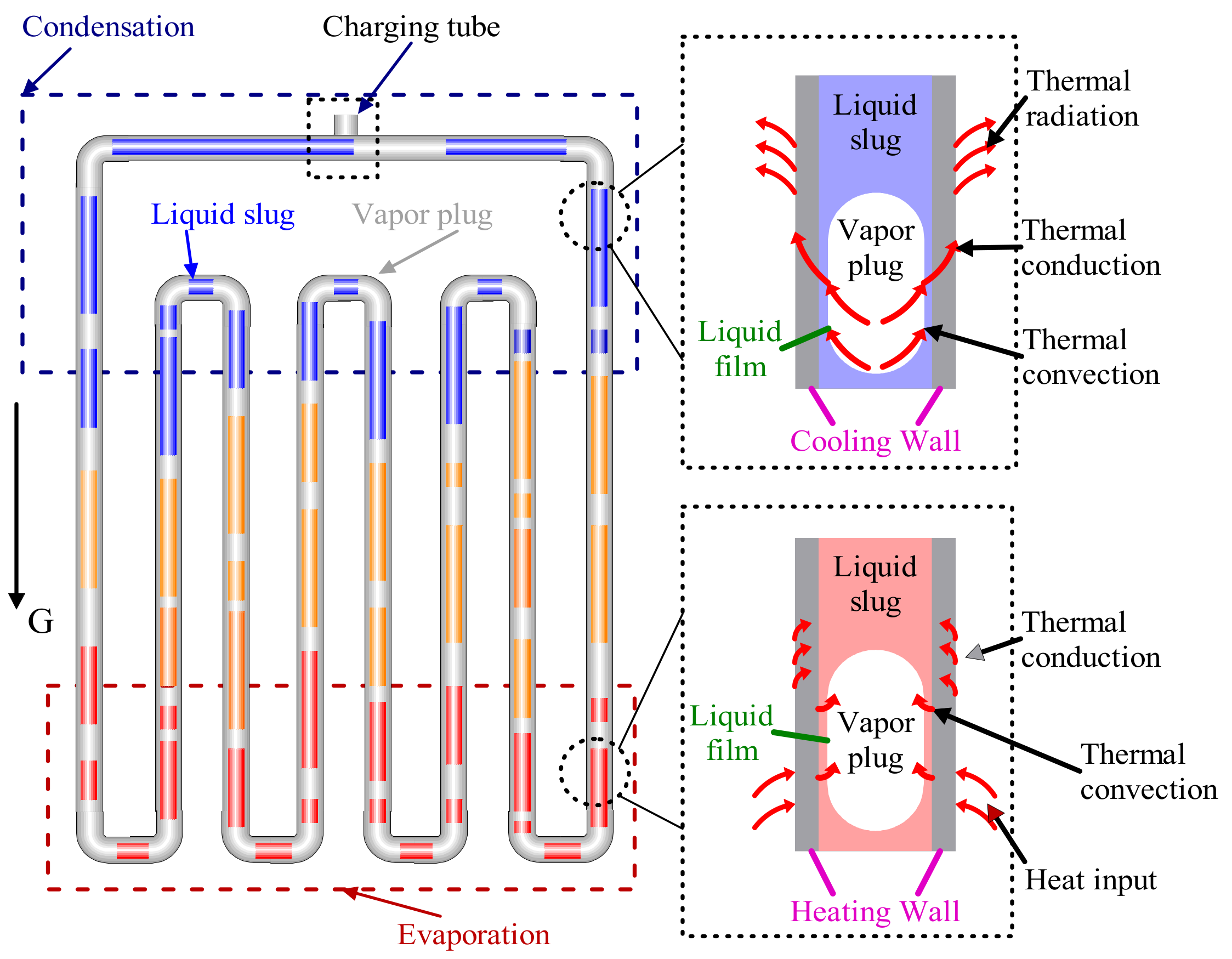
2.1. Heat Dissipation Mechanism of the OHP
2.2. Technical Characteristics of OHP
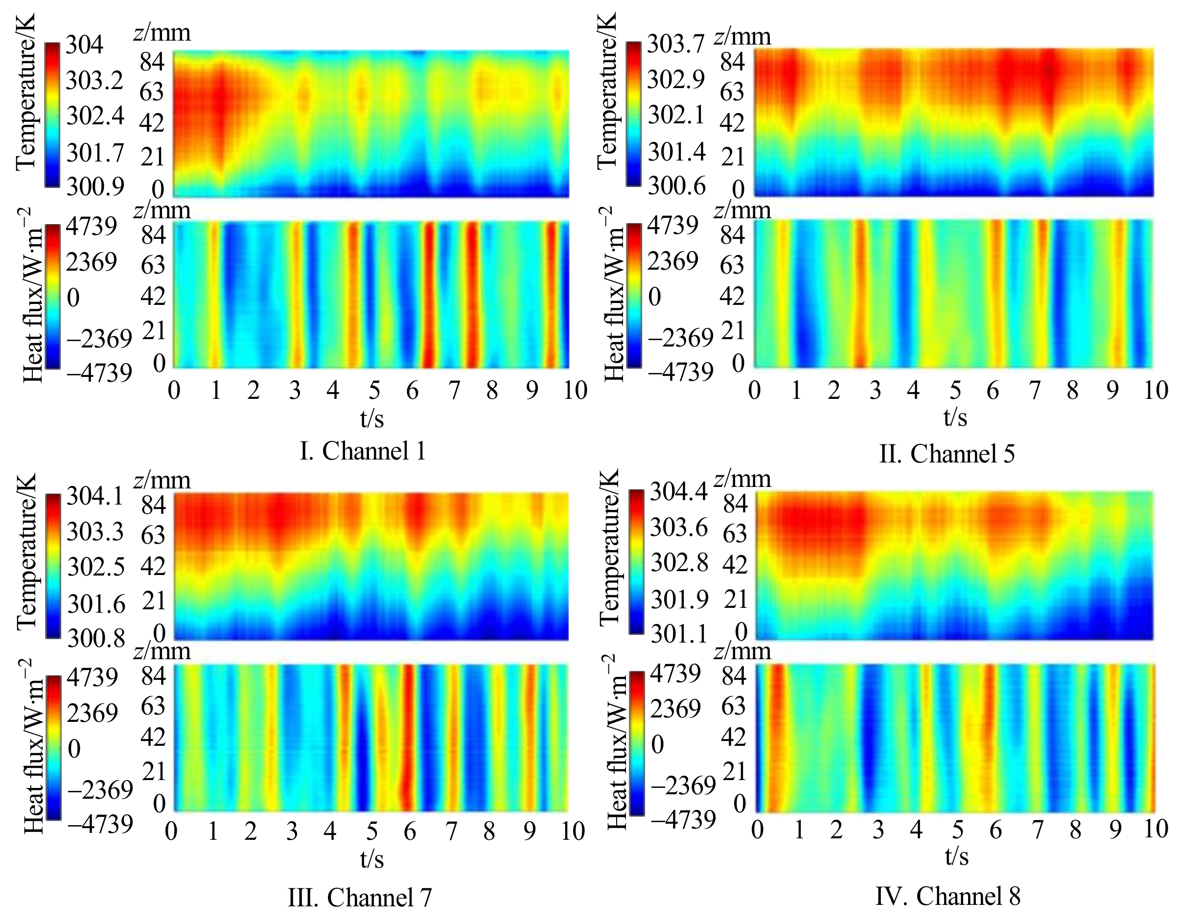
2.2.1. Excellent Heat Transfer Performance
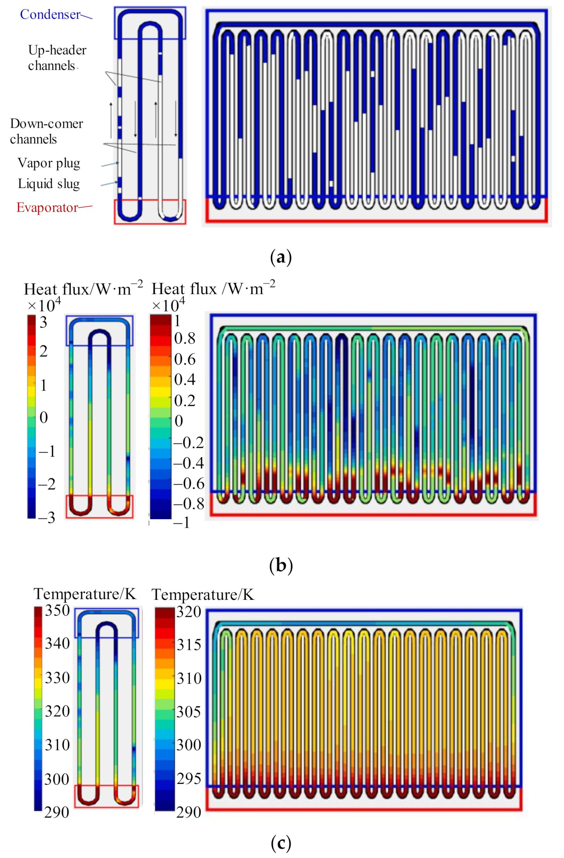
2.2.2. Simple Structure of the OHP with a Small Volume
3. Effect of Various Filling Working Fluids of OHPs on Heat Dissipation
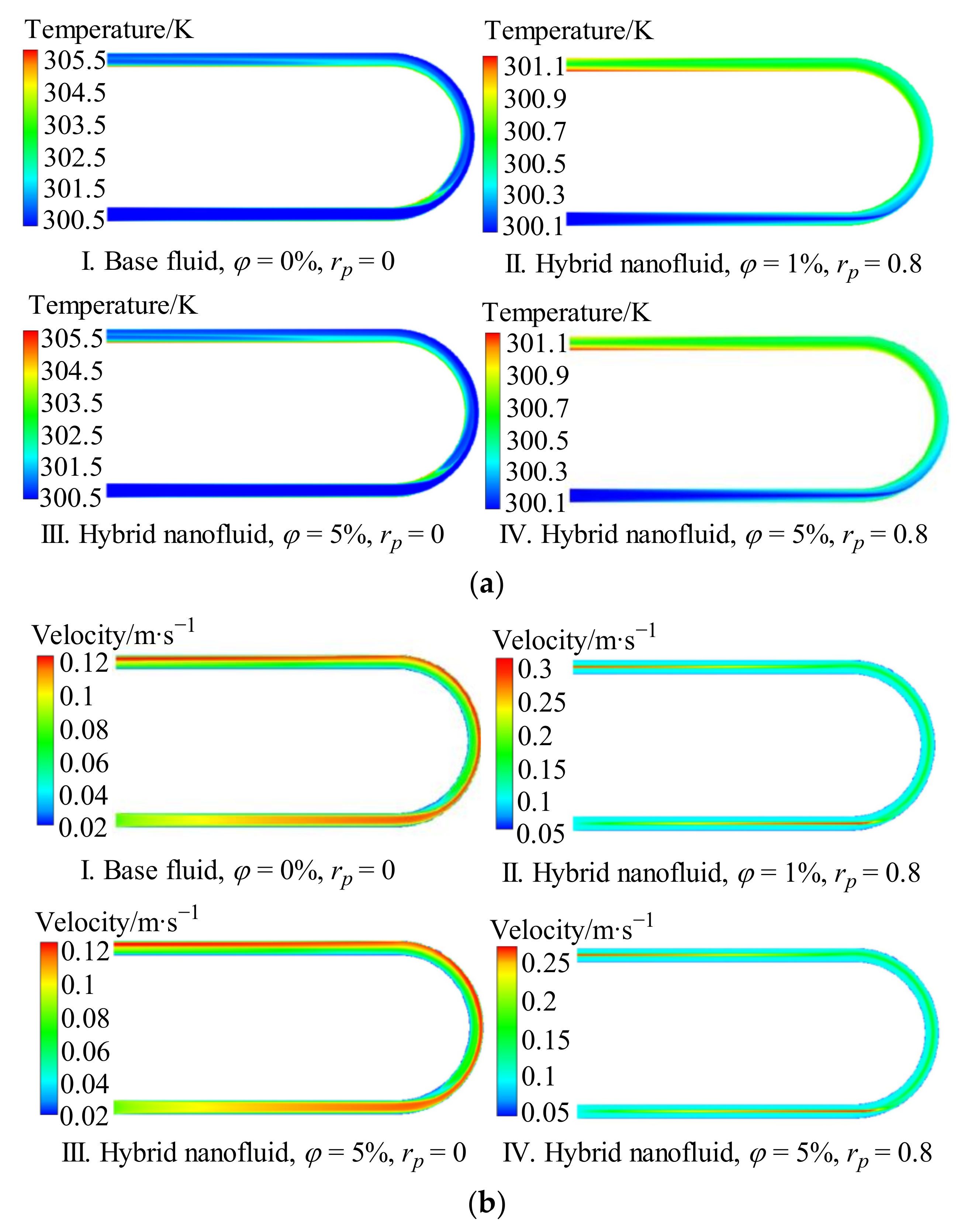
3.1. Metal Nano-Fluid
3.2. Non-Metallic Nano-Fluid
3.3. Mixed Nano-Fluid
3.4. Gas Working Fluid
3.5. Organic Solvent
3.6. Mix Liquids
3.7. Surfactants and Self-Rewetting Fluids
4. Effect of In-Tube Flow State on Heat Dissipation Properties
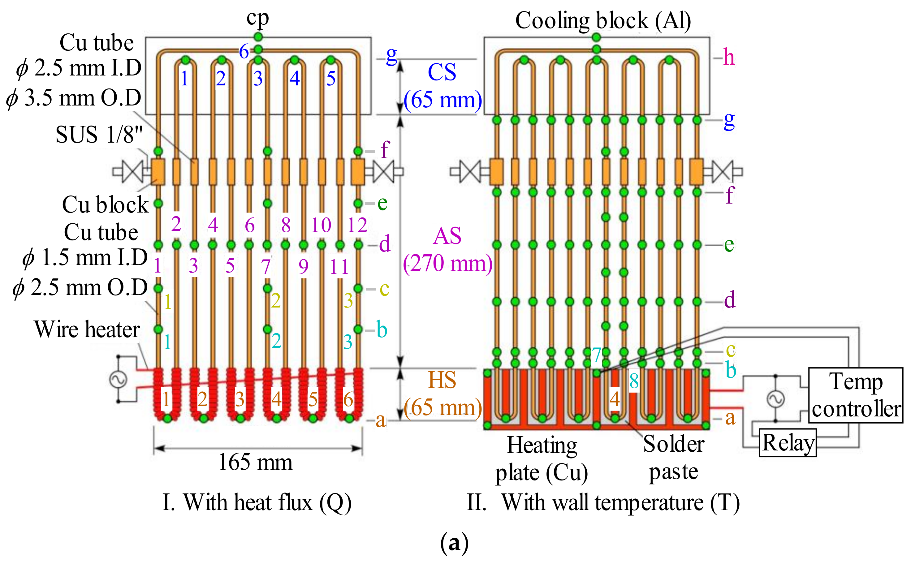
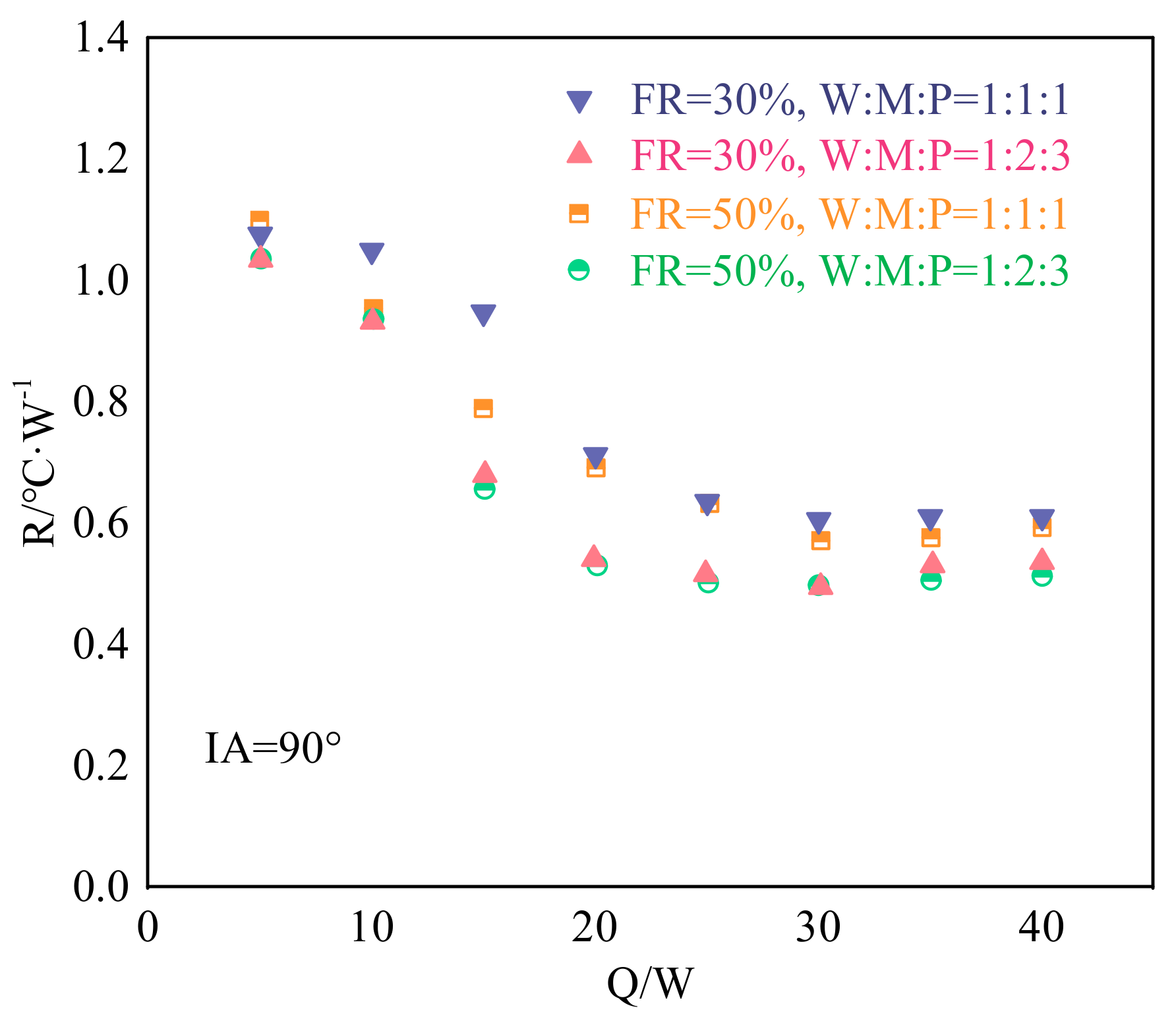
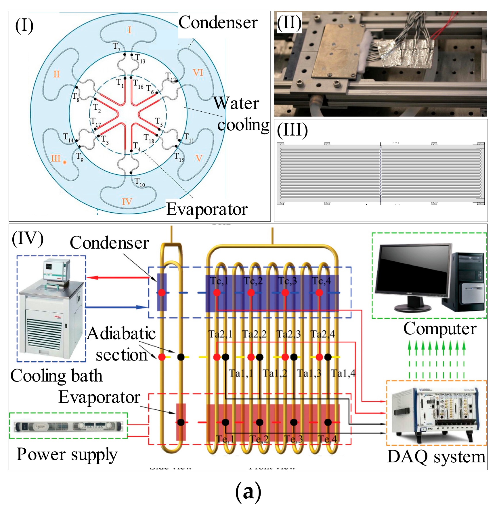
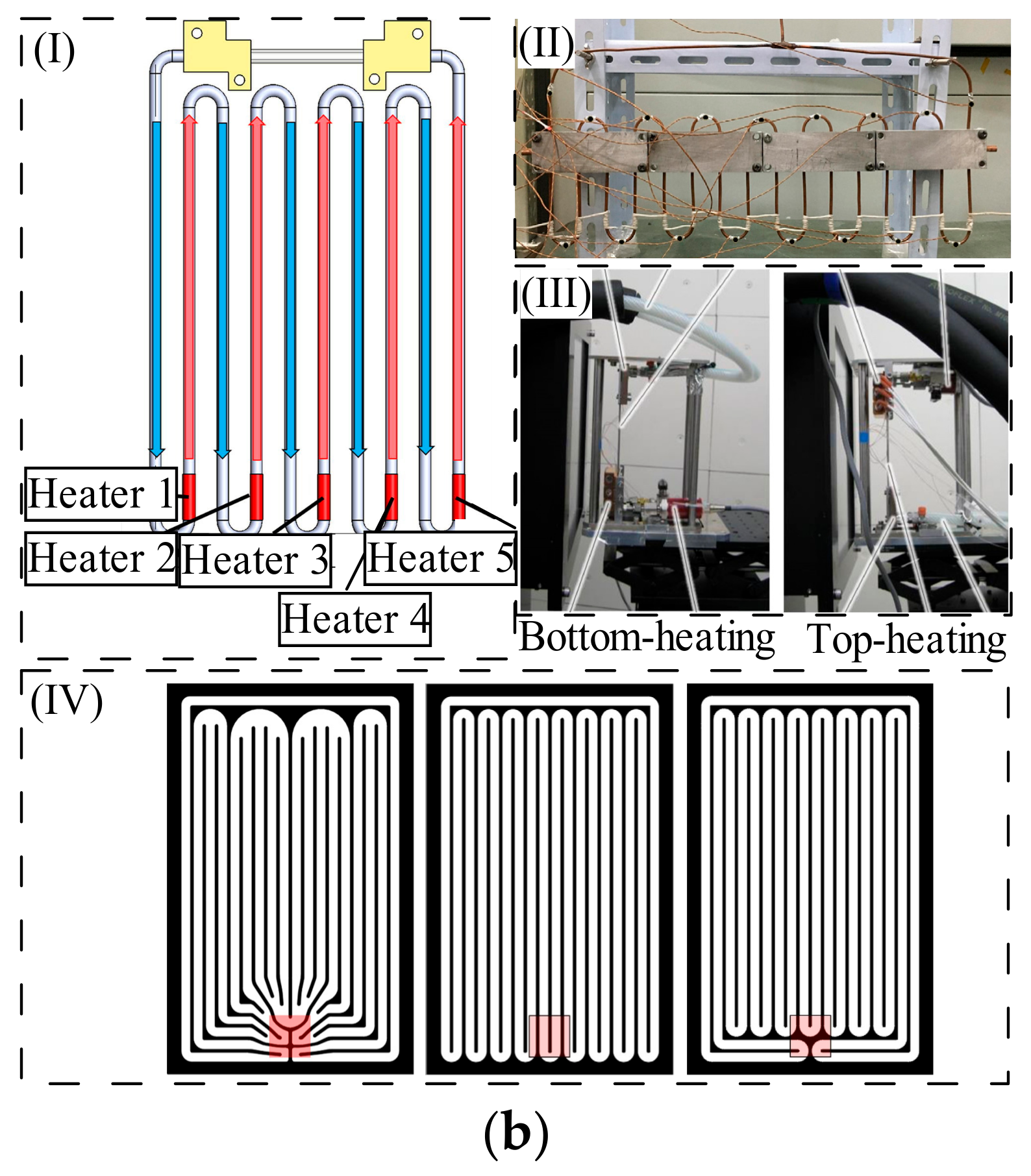
4.1. Different Heating Method of Evaporation Section
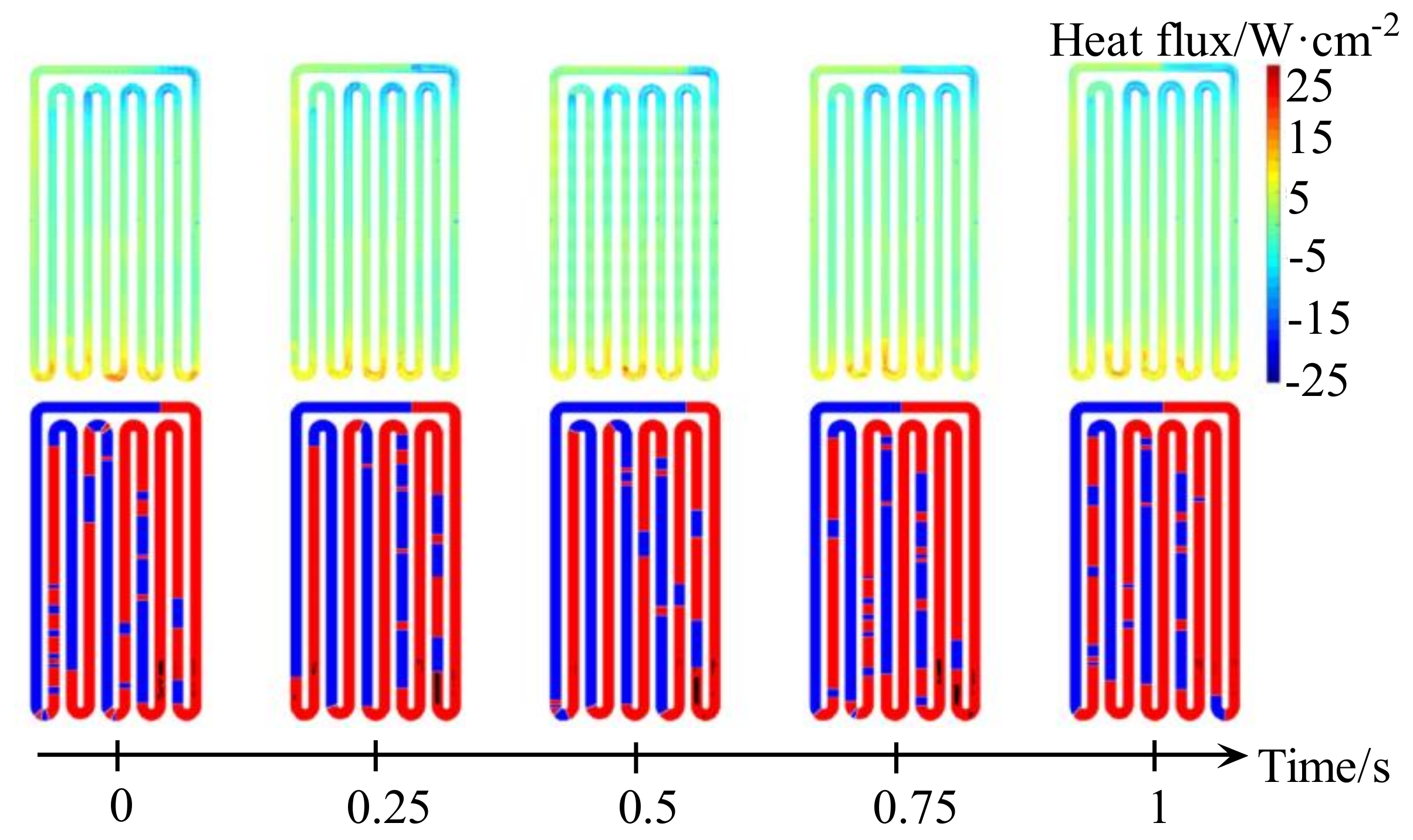
4.2. Flow State
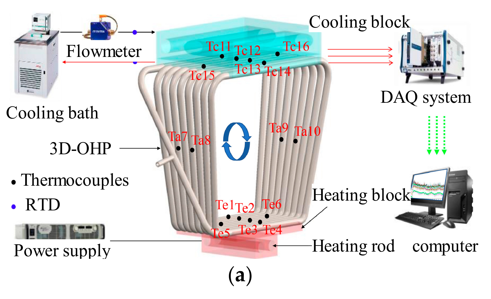
4.3. Gravity Effect
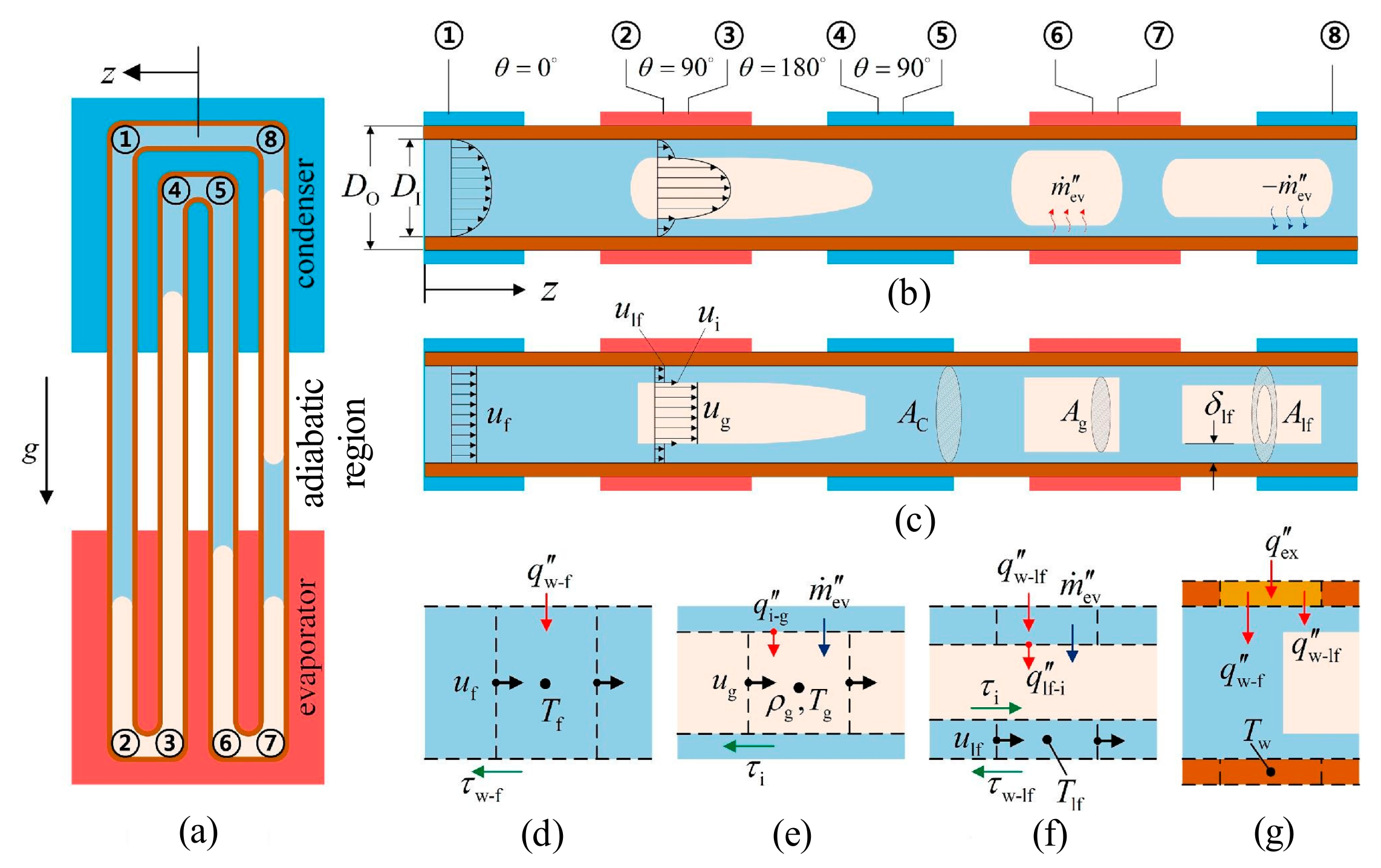
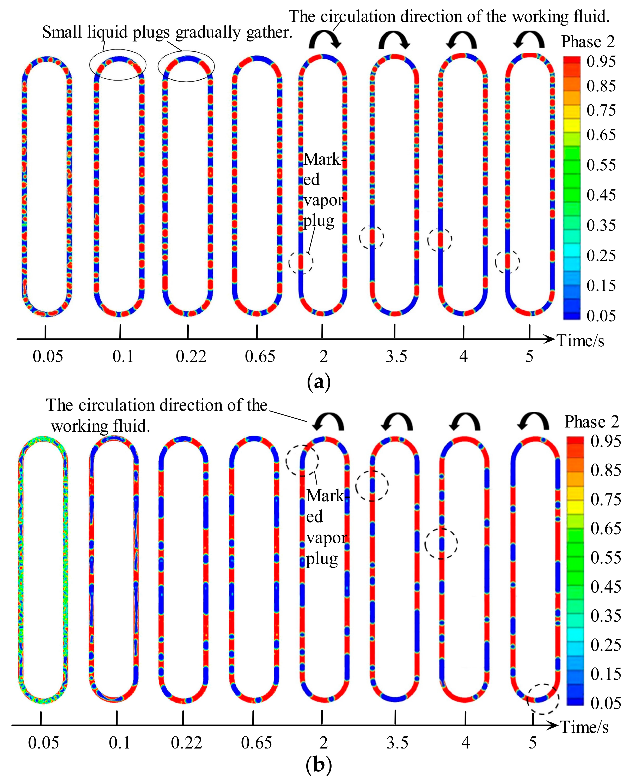
4.4. Characteristics of Flow Pattern in Tube
4.5. Oscillatory Characteristics
5. Bibliometric Study and Analysis
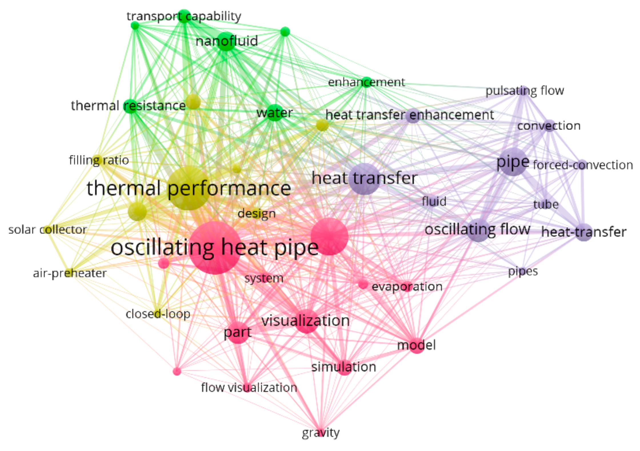
5.1. Publication Year and Number of Publications
5.2. Keyword Distribution
6. Current Research Shortcomings and Prospects for Future Works
6.1. Shortcomings of the Current Studies
- (1)
- Effects of channel layout
- (2)
- Limitation of materials
- (3)
- Insufficient understanding of working fluid properties
- (4)
- Inadequate recognition of the heat transfer mechanism
- (5)
- Limitations of the actual application environment
6.2. Prospects for Future Research
- (1)
- Further study of mixed nano-fluids
- (2)
- Study of non-azeotropic mixtures
- (3)
- The improvement in the numerical model
- (4)
- The combination of artificial intelligence technology
7. Conclusions
- (1)
- With the addition of non-metallic nano-fluids in OHPs, the thermal resistance decreases from 24% to 83.6% with the change in the type, size, and concentration of nano-particles. The maximum heat pipe thermal conductivity was enhanced by 105% with the graphene nano-fluids. OHPs with gas as the working fluid can be used in the field of low temperature cooling. The effective thermal conductivity varies from 4.8 kW/(m·K) to 70 kW/(m·K) when different gases are selected as the working fluid in OHPs.
- (2)
- Compared with the pure working fluid, the thermal resistance of OHPs can be reduced by 68.9% with the right mixture type, filling rate, and mixing ratio. The surfactant and SRWF can be added to reduce the surface tension of the working fluid and the thermal resistance of the OHP can be reduced by 4.78% to 60%.
- (3)
- The change in gravity has a significant effect on the heat transfer performance of OHPs with vertical heating. A sensible heat transfer can account for more than 80% of the total heat transfer when the internal flow type of OHPs is the slug flow. The heat transfer performance is enhanced with the increase in the oscillatory flow, amplitude and the effective thermal conductivity can reach 40 kW/(m·K). The input power is increased from 7 W to 16 W, the oscillation amplitude is increased from 3.4 mm to 8.3 mm, and the thermal resistance is reduced by 13.5%.
Author Contributions
Funding
Data Availability Statement
Conflicts of Interest
Nomenclature
| Rth | the thermal resistance, K/W |
| the average temperature of the evaporation, K | |
| the average temperature of the condensation, K | |
| Qin | the input power, W |
| ta | the time interval for time averaging, s |
| W | the width of OHP, m |
| L | the length of OHP, m |
| TSi | the temperature of the silicon substrate, K |
| x | the horizontal coordinate, m |
| t | the time, s |
| Qw,H | the total heat transferred from the heating wall to the liquid film, W |
| Qw,C | the total heat transferred from the liquid film to the cooling wall, W |
| Tw | the wall temperature, K |
| Tsur,H | the temperature of liquid film during heating K |
| Tsur,C | the temperature of cooling, respectively, K |
| λl | the thermal conductivity of the liquid, W/(m·K) |
| δ | the liquid film thickness, m |
| cp,l | the specific heat of the liquid, J/(kg·K) |
| ρl | the density of the liquid, kg/m3 |
| Acr | the cross-sectional area of the flow path, m2 |
| Tw | the temperature of the channel wall, K |
| Tl | the temperature of liquid plug, K |
| hw,l | the heat transfer coefficient between channel wall and liquid plug, W/(m2·K) |
| S | the perimeter of the liquid plug, m |
| Tv | the temperature of the vapor plug, K |
| Qv,sen | the total amount of sensible heat, W |
| Qv,lat | the total amount of latent heat, W |
| Pv | the pressure of vapor plug, Pa |
| Vv | the volume of the vapor plug, m3 |
| cv,v | the specific heat at constant volume, J/(kg·K) |
| mv | the mass of the vapor plug, kg |
| the phase change local mass flow rate, kg/(m3·s) | |
| Lv | the latent heat |
| cp,v | the constant pressure specific heat of vapor, J/(kg·K) |
| Tsat | the saturation temperature associated with the considered pressure, K |
| Tint | the local interface temperature, K |
| klv | the thermal conductivity, W/(m·K) |
| the normal vector pointing in the direction of the gas phase at the Γ of the interface | |
| γ | the adjustment factor |
| M | the molecular weight |
| Rg | the general gas constant, J/(mol·K) |
| ρv | the density of vapor, kg/m3 |
| Tif | the interface temperature, K |
| the mass transfer of each time step in the evaporation process, kg/(m3·s) | |
| the mass transfer of each time step in the condensation process, kg/(m3·s) | |
| αl | the volume fraction of liquid |
| αv | the volume fraction of vapor |
| MCOHP | Micro-channel oscillating heat pipe |
| OHP | Oscillating heat pipe |
| TS | Tube diameter |
| CVOHP | Oscillating heat pipe with check valves |
| CLOHP | Closed-loop oscillating heat pipe |
| FPOHP | Flat-plate oscillating heat pipe |
| SRWF | Self-rewetting fluid |
| MWCNTs | Multi walled carbon nano-tubes |
| EOHP | Ethane oscillating heat pipe |
| CTOHP | Capillary tube oscillating heat pipe |
| CTAC | Cetyltrimethylammonium chloride |
| CTAB | Cetyltrimethylammonium bromide |
| VOF | Volume of fluid |
References
- Zhao, D.; Guan, Y. Characterizing Modal Exponential Behaviors of Self-excited Transverse and Longitudinal Combustion Instabilities. Phys. Fluids 2022, 34, 024109. [Google Scholar] [CrossRef]
- Zhao, D.; Ji, C. Non-orthogonality analysis of thermoacoustic system with a premixed V-shaped flame. Energy Convers. Manag. 2014, 85, 102–111. [Google Scholar]
- Li, S.; Zhao, D.; Li, J. Combustion Instabilities in a Bifurcating Tube: Open- and Closed-loop Measurements. AIAA J. 2014, 52, 2513–2523. [Google Scholar] [CrossRef]
- Zhao, D.; Li, J. Prediction of stability behaviors of longitudinal and circumferential eigenmodes in a choked thermoacoustic combustor. Aerosp. Sci. Technol. 2015, 46, 12–21. [Google Scholar]
- Zhao, D.; Guan, Y.; Reinecke, A. Characterizing Hydrogen-fuelled Pulsating Combustion on Thermodynamic Properties of a Combustor. Commun. Phys. 2019, 2, 44. [Google Scholar] [CrossRef]
- Zhao, X.; Jiaqiang, E.; Liao, G.; Zhang, F.; Chen, J.; Deng, Y. Numerical simulation study on soot continuous regeneration combustion model of diesel particulate filter under exhaust gas heavy load. Fuel 2021, 290, 119795. [Google Scholar] [CrossRef]
- Zhao, X.; Jiaqiang, E.; Zhang, Z.; Chen, J.; Liao, G.; Zhang, F.; Leng, E.; Han, D.; Hu, W. A review on heat enhancement in thermal energy conversion and management using Field Synergy Principle. Appl. Energy 2020, 257, 113995. [Google Scholar] [CrossRef]
- Ji, C.; Zhao, D. Two-dimensional lattice Boltzmann investigation of sound absorption of perforated orifices with different geometric shapes. Aerosp. Sci. Technol. 2014, 39, 40–47. [Google Scholar] [CrossRef]
- Zhao, D.; Reyhanoglu, M. Feedback control of acoustic disturbance transient growth in triggering thermoacoustic instability. J. Sound Vib. 2014, 333, 3639–3656. [Google Scholar] [CrossRef]
- Zhao, D.; Gutmark, E.; Reneicke, A. Mitigating self-excited flame pulsating and thermoacoustic oscillations using perforated liners. Sci. Bull. 2019, 64, 941–952. [Google Scholar] [CrossRef]
- Zhao, D.; Li, S.; Yang, W.; Zhang, Z. Numerical investigation of the effect of distributed heat sources on heat-to-sound conversion in a T-shaped thermoacoustic system. Appl. Energy 2015, 144, 204–213. [Google Scholar] [CrossRef]
- Zhang, Z.; Zhao, D.; Ni, S.; Sun, Y.Z.; Wang, B.; Chen, Y.; Li, G.; Li, S. Experimental characterizing combustion emissions and thermodynamic properties of a thermoacoustic swirl combustor. Appl. Energy 2019, 235, 463–472. [Google Scholar] [CrossRef]
- Zhao, D. Transient growth of flow disturbances in triggering a Rijke tube combustion instability. Combust. Flame 2012, 159, 2126–2137. [Google Scholar] [CrossRef]
- Thompson, S.M.; Ma, H.B.; Winholtz, R.A.; Wilson, C. Experimental investigation of miniature three-dimensional flat-plate oscillating heat pipe. J. Heat Transf. 2009, 131, 043210. [Google Scholar] [CrossRef]
- Zhao, D.; Qin, J.; Zheng, L.; Cao, M. Amorphous vanadium oxide/molybdenum oxide hybrid with three-dimensional ordered hierarchically porous structure as a high-performance Li-ion battery anode. Chem. Mater. 2016, 28, 4180–4190. [Google Scholar] [CrossRef]
- Im, Y.H.; Lee, J.Y.; Ahn, T.I.; Youn, Y.J. Operational characteristics of oscillating heat pipe charged with R-134a for heat recovery at low temperature. Int. J. Heat Mass Transf. 2022, 196, 123231. [Google Scholar] [CrossRef]
- Charoensawan, P.; Wilaipon, P.; Seehawong, N. Flat plate solar water heater with closed-loop oscillating heat pipes. Therm. Sci. 2021, 25 Pt A, 3607–3614. [Google Scholar] [CrossRef]
- Dehshali, M.E.; Nazari, M.A.; Shafii, M.B. Thermal performance of rotating closed-loop pulsating heat pipes: Experimental investigation and semi-empirical correlation. Int. J. Therm. Sci. 2018, 123, 14–26. [Google Scholar] [CrossRef]
- Rittidech, S.; Sangiamsuk, S. Internal flow patterns on heat transfer performance of a closed-loop oscillating heat pipe with check valves. Exp. Heat Transf. 2012, 25, 48–57. [Google Scholar] [CrossRef]
- Gully, P.; Bonnet, F.; Nikolayev, V.S.; Luchier, N.; Tran, T.Q. Evaluation of the vapor thermodynamic state in PHP. Heat Pipe Sci. Technol. Int. J. 2014, 5, 369–376. [Google Scholar] [CrossRef]
- Barrak, A.S.; Saleh, A.A.M.; Naji, Z.H. An experimental study of using water, methanol, and binary fluids in oscillating heat pipe heat exchanger. Eng. Sci. Technol. Int. J. 2020, 23, 357–364. [Google Scholar] [CrossRef]
- Shafii, M.B.; Arabnejad, S.; Saboohi, Y.; Jamshidi, H. Experimental investigation of pulsating heat pipes and a proposed correlation. Heat Transf. Eng. 2010, 31, 854–861. [Google Scholar] [CrossRef]
- Lin, H.; Tian, P.; Luo, C.; Wang, H.; Zhang, J.; Yang, J.; Peng, H. Luminescent nanofluids of organometal halide perovskite nanocrystals in silicone oils with ultrastability. ACS Appl. Mater. Interfaces 2018, 10, 27244–27251. [Google Scholar] [CrossRef] [PubMed]
- Senjaya, R.; Inoue, T. Bubble generation in oscillating heat pipe. Appl. Therm. Eng. 2013, 60, 251–255. [Google Scholar] [CrossRef]
- Ando, M.; Okamoto, A.; Nagai, H. Start-up and heat transfer characteristics of oscillating heat pipe with different check valve layouts. Appl. Therm. Eng. 2021, 196, 117286. [Google Scholar] [CrossRef]
- Wang, W.W.; Wang, L.; Cai, Y.; Yang, G.B.; Zhao, F.Y.; Liu, D.; Yu, Q.H. Thermo-hydrodynamic model and parametric optimization of a novel miniature closed oscillating heat pipe with periodic expansion-constriction condensations. Int. J. Heat Mass Transf. 2020, 152, 119460. [Google Scholar] [CrossRef]
- Shi, W.; Chen, H.; Pan, L.; Wang, Q. Starting and running performance of a pulsating heat pipe with micro encapsulated phase change material suspension. Appl. Therm. Eng. 2022, 212, 118626. [Google Scholar] [CrossRef]
- Lim, J.; Kim, S.J. Effect of a channel layout on the thermal performance of a flat plate micro pulsating heat pipe under the local heating condition. Int. J. Heat Mass Transf. 2019, 137, 1232–1240. [Google Scholar] [CrossRef]
- Liu, X.; Han, X.; Wang, Z.; Hao, G.; Zhang, Z.; Chen, Y. Application of an anti-gravity oscillating heat pipe on enhancement of waste heat recovery. Energy Convers. Manag. 2020, 205, 112404. [Google Scholar] [CrossRef]
- Hao, T.; Ma, H.; Ma, X. Experimental investigation of oscillating heat pipe with hybrid fluids of liquid metal and water. J. Heat Transf. 2019, 141, 071802. [Google Scholar] [CrossRef]
- Schwarz, F.; Messmer, P.; Lodermeyer, A.; Danov, V.; Fleßner, C.; Becker, S.; Hellinger, R. Analysis of improved pulsating heat pipe designs for hot spot applications. Int. J. Heat Mass Transf. 2022, 196, 123294. [Google Scholar] [CrossRef]
- Kwon, G.H.; Kim, S.J. Operational characteristics of pulsating heat pipes with a dual-diameter tube. Int. J. Heat Mass Transf. 2014, 75, 184–195. [Google Scholar] [CrossRef]
- Liu, X.; Chen, X.; Zhang, Z.; Chen, Y. Thermal performance of a novel dual-serpentine-channel flat-plate oscillating heat pipe used for multiple heat sources and sinks. Int. J. Heat Mass Transf. 2020, 161, 120293. [Google Scholar] [CrossRef]
- Arai, T.; Kawaji, M. Thermal performance and flow characteristics in additive manufactured polycarbonate pulsating heat pipes with Novec 7000. Appl. Therm. Eng. 2021, 197, 117273. [Google Scholar] [CrossRef]
- Okazaki, S.; Fuke, H.; Ogawa, H. Performance of circular Oscillating Heat Pipe for highly adaptable heat transfer layout. Appl. Therm. Eng. 2021, 198, 117497. [Google Scholar] [CrossRef]
- Kim, S.; Zhang, Y.; Choi, J. Effects of fluctuations of heating and cooling section temperatures on performance of a pulsating heat pipe. Appl. Therm. Eng. 2013, 58, 42–51. [Google Scholar] [CrossRef]
- Barba, M.; Bruce, R.; Bouchet, F.; Bonelli, A.; Baudouy, B. Effect of the thermo-physical properties of the working fluid on the performance of a 1-m long cryogenic horizontal pulsating heat pipe. Int. J. Heat Mass Transf. 2022, 187, 122458. [Google Scholar] [CrossRef]
- Monroe, J.G.; Ibrahim, O.T.; Thompson, S.M. Effect of harvesting module design on the thermal performance and voltage generation of a thermoelectric oscillating heat pipe. Appl. Therm. Eng. 2022, 201, 117651. [Google Scholar] [CrossRef]
- Bastakoti, D.; Zhang, H.; Li, D.; Cai, W.; Li, F. An overview on the developing trend of pulsating heat pipe and its performance. Appl. Therm. Eng. 2018, 141, 305–332. [Google Scholar] [CrossRef]
- Gürsel, G.; Frijns, A.J.H.; Homburg, F.G.A.; Van Steenhoven, A.A. A mass-spring-damper model of a pulsating heat pipe with a non-uniform and asymmetric filling. Appl. Therm. Eng. 2015, 91, 80–90. [Google Scholar] [CrossRef]
- Liu, J.; Xie, G.; Sundén, B. Flow pattern and heat transfer past two tandem arranged cylinders with oscillating inlet velocity. Appl. Therm. Eng. 2017, 120, 614–625. [Google Scholar] [CrossRef]
- Tong, B.Y.; Wong, T.N.; Ooi, K.T. Closed-loop pulsating heat pipe. Appl. Therm. Eng. 2001, 21, 1845–1862. [Google Scholar] [CrossRef]
- Jo, J.; Kim, J.; Kim, S.J. Experimental investigations of heat transfer mechanisms of a pulsating heat pipe. Energy Convers. Manag. 2019, 181, 331–341. [Google Scholar] [CrossRef]
- Senjaya, R.; Inoue, T. Oscillating heat pipe simulation considering bubble generation Part I: Presentation of the model and effects of a bubble generation. Int. J. Heat Mass Transf. 2013, 60, 816–824. [Google Scholar] [CrossRef]
- Yoon, A.; Kim, S.J. A deep-learning approach for predicting oscillating motion of liquid slugs in a closed-loop pulsating heat pipe. Int. J. Heat Mass Transf. 2021, 181, 121860. [Google Scholar] [CrossRef]
- Yu, C.; Ji, Y.; Li, Y.; Liu, Z.; Chu, L.; Kuang, H.; Wang, Z. A three-dimensional oscillating heat pipe filled with liquid metal and ammonia for high-power and high-heat-flux dissipation. Int. J. Heat Mass Transf. 2022, 194, 123096. [Google Scholar] [CrossRef]
- Thompson, S.M.; Cheng, P.; Ma, H.B. An experimental investigation of a three-dimensional flat-plate oscillating heat pipe with staggered microchannels. Int. J. Heat Mass Transf. 2011, 54, 3951–3959. [Google Scholar] [CrossRef]
- Ji, Y.; Wu, M.; Feng, Y.; Yu, C.; Chu, L.; Chang, C.; Li, Y.; Xiao, X.; Ma, H. An experimental investigation on the heat transfer performance of a liquid metal high-temperature oscillating heat pipe. Int. J. Heat Mass Transf. 2020, 149, 119198. [Google Scholar] [CrossRef]
- Ji, Y.; Wu, M.; Feng, Y.; Liu, H.; Yang, X.; Li, Y.; Chang, C. Experimental study on the effects of sodium and potassium proportions on the heat transfer performance of liquid metal high-temperature oscillating heat pipes. Int. J. Heat Mass Transf. 2022, 194, 123116. [Google Scholar] [CrossRef]
- Czajkowski, C.; Nowak, A.I.; Ochman, A.; Pietrowicz, S. Flower Shaped Oscillating Heat Pipe at the thermosyphon condition: Performance at different rotational speeds, filling ratios, and heat supplies. Appl. Therm. Eng. 2022, 212, 118540. [Google Scholar] [CrossRef]
- Qu, J.; Wu, H.; Cheng, P. Thermal performance of an oscillating heat pipe with Al2O3–water nanofluids. Int. Commun. Heat Mass Transf. 2010, 37, 111–115. [Google Scholar] [CrossRef]
- Qu, J.; Wang, Q. Experimental study on the thermal performance of vertical closed-loop oscillating heat pipes and correlation modeling. Appl. Energy 2013, 112, 1154–1160. [Google Scholar] [CrossRef]
- Tokuda, D.; Inoue, T. Heat transport characteristics of a sodium oscillating heat pipe: Thermal performance. Int. J. Heat Mass Transf. 2022, 196, 123281. [Google Scholar] [CrossRef]
- Zhao, J.; Qu, J.; Rao, Z. Experiment investigation on thermal performance of a large-scale oscillating heat pipe with self-rewetting fluid used for thermal energy storage. Int. J. Heat Mass Transf. 2017, 108, 760–769. [Google Scholar] [CrossRef]
- Lin, Z.; Wang, S.; Huo, J.; Hu, Y.; Chen, J.; Zhang, W.; Lee, E. Heat transfer characteristics and LED heat sink application of aluminum plate oscillating heat pipes. Appl. Therm. Eng. 2011, 31, 2221–2229. [Google Scholar] [CrossRef]
- Qian, N.; Fu, Y.; Zhang, Y.; Chen, J.; Xu, J. Experimental investigation of thermal performance of the oscillating heat pipe for the grinding wheel. Int. J. Heat Mass Transf. 2019, 136, 911–923. [Google Scholar] [CrossRef]
- Monroe, J.G.; Ibrahim, O.T.; Thompson, S.M.; Shamsaei, N. Energy harvesting via fluidic agitation of a magnet within an oscillating heat pipe. Appl. Therm. Eng. 2018, 129, 884–892. [Google Scholar] [CrossRef]
- Zhao, J.; Rao, Z.; Liu, C.; Li, Y. Experimental investigation on thermal performance of phase change material coupled with closed-loop oscillating heat pipe (PCM/CLOHP) used in thermal management. Appl. Therm. Eng. 2016, 93, 90–100. [Google Scholar] [CrossRef]
- Qu, J.; Ke, Z.; Zuo, A.; Rao, Z. Experimental investigation on thermal performance of phase change material coupled with three-dimensional oscillating heat pipe (PCM/3D-OHP) for thermal management application. Int. J. Heat Mass Transf. 2019, 129, 773–782. [Google Scholar] [CrossRef]
- Jin, H.; Lin, G.; Zeiny, A.; Bai, L.; Cai, J.; Wen, D. Experimental study of transparent oscillating heat pipes filled with solar absorptive nanofluids. Int. J. Heat Mass Transf. 2019, 139, 789–801. [Google Scholar] [CrossRef]
- Alqahtani, A.A.; Edwardson, S.; Marengo, M.; Bertola, V. Performance of flat-plate, flexible polymeric pulsating heat pipes at different bending angles. Appl. Therm. Eng. 2022, 216, 118948. [Google Scholar] [CrossRef]
- Iwata, N.; Miyazaki, Y.; Yasuda, S.; Ogawa, H. Thermal performance and flexibility evaluation of metallic micro oscillating heat pipe for thermal strap. Appl. Therm. Eng. 2021, 197, 117342. [Google Scholar] [CrossRef]
- Wei, A.; Qu, J.; Qiu, H.; Wang, C.; Cao, G. Heat transfer characteristics of plug-in oscillating heat pipe with binary-fluid mixtures for electric vehicle battery thermal management. Int. J. Heat Mass Transf. 2019, 135, 746–760. [Google Scholar] [CrossRef]
- Tsai, C.Y.; Chien, H.T.; Ding, P.P.; Chan, B.; Luh, T.Y.; Chen, P.H. Effect of structural character of gold nanoparticles in nanofluid on heat pipe thermal performance. Mater. Lett. 2004, 58, 1461–1465. [Google Scholar] [CrossRef]
- Ma, H.B.; Wilson, C.; Borgmeyer, B.; Park, K.; Yu, Q.; Choi, S.U.S.; Tirumala, M. Effect of nanofluid on the heat transport capability in an oscillating heat pipe. Appl. Phys. Lett. 2006, 88, 143116. [Google Scholar] [CrossRef]
- Kang, S.W.; Wei, W.C.; Tsai, S.H.; Huang, C.C. Experimental investigation of nanofluids on sintered heat pipe thermal performance. Appl. Therm. Eng. 2009, 29, 973–979. [Google Scholar] [CrossRef]
- Naphon, P.; Thongkum, D.; Assadamongkol, P. Heat pipe efficiency enhancement with refrigerant–nanoparticles mixtures. Energy Convers. Manag. 2009, 50, 772–776. [Google Scholar] [CrossRef]
- Hajian, R.; Layeghi, M.; Sani, K.A. Experimental study of nanofluid effects on the thermal performance with response time of heat pipe. Energy Convers. Manag. 2012, 56, 63–68. [Google Scholar] [CrossRef]
- Aydın, D.Y.; Aydın, E.; Guru, M. The effects of particle mass fraction and static magnetic field on the thermal performance of NiFe2O4 nanofluid in a heat pipe. Int. J. Therm. Sci. 2023, 183, 107875. [Google Scholar] [CrossRef]
- Wang, S.; Lin, Z.; Zhang, W.; Chen, J. Experimental study on pulsating heat pipe with functional thermal fluids. Int. J. Heat Mass Transf. 2009, 52, 5276–5279. [Google Scholar] [CrossRef]
- Qu, J.; Wu, H. Thermal performance comparison of oscillating heat pipes with SiO2/water and Al2O3/water nanofluids. Int. J. Therm. Sci. 2011, 50, 1954–1962. [Google Scholar] [CrossRef]
- Hung, Y.H.; Teng, T.P.; Lin, B.G. Evaluation of the thermal performance of a heat pipe using alumina nanofluids. Exp. Therm. Fluid Sci. 2013, 44, 504–511. [Google Scholar] [CrossRef]
- Goshayeshi, H.R.; Goodarzi, M.; Safaei, M.R.; Dahari, M. Experimental study on the effect of inclination angle on heat transfer enhancement of a ferrofluid in a closed loop oscillating heat pipe under magnetic field. Exp. Therm. Fluid Sci. 2016, 74, 265–270. [Google Scholar] [CrossRef]
- Davari, H.; Goshayeshi, H.R.; Öztop, H.F.; Chaer, I. Experimental investigation of oscillating heat pipe efficiency for a novel condenser by using Fe3O4 nanofluid. J. Therm. Anal. Calorim. 2020, 140, 2605–2614. [Google Scholar] [CrossRef]
- Goshayeshi, H.R.; Safaei, M.R.; Goodarzi, M.; Dahari, M. Particle size and type effects on heat transfer enhancement of Ferro-nanofluids in a pulsating heat pipe. Powder Technol. 2016, 301, 1218–1226. [Google Scholar] [CrossRef]
- Kang, S.W.; Wang, Y.C.; Liu, Y.C.; Lo, H.M. Visualization and thermal resistance measurements for a magnetic nanofluid pulsating heat pipe. Appl. Therm. Eng. 2017, 126, 1044–1050. [Google Scholar] [CrossRef]
- Karthikeyan, V.K.; Ramachandran, K.; Pillai, B.C.; Solomon, A.B. Effect of nanofluids on thermal performance of closed loop pulsating heat pipe. Exp. Therm. Fluid Sci. 2014, 54, 171–178. [Google Scholar] [CrossRef]
- Kim, H.J.; Lee, S.H.; Kim, S.B.; Jang, S.P. The effect of nanoparticle shape on the thermal resistance of a flat-plate heat pipe using acetone-based Al2O3 nanofluids. Int. J. Heat Mass Transf. 2016, 92, 572–577. [Google Scholar] [CrossRef]
- Jafarmadar, S.; Azizinia, N.; Razmara, N.; Mobadersani, F. Thermal analysis and entropy generation of pulsating heat pipes using nanofluids. Appl. Therm. Eng. 2016, 103, 356–364. [Google Scholar] [CrossRef]
- Goshayeshi, H.R.; Chaer, I. Experimental study and flow visualization of Fe2O3/kerosene in glass oscillating heat pipes. Appl. Therm. Eng. 2016, 103, 1213–1218. [Google Scholar] [CrossRef]
- Goshayeshi, H.R.; Izadi, F.; Bashirnezhad, K. Comparison of heat transfer performance on closed pulsating heat pipe for Fe3O4 and ɤFe2O3 for achieving an empirical correlation. Phys. E Low-Dimens. Syst. Nanostructures 2017, 89, 43–49. [Google Scholar] [CrossRef]
- Gandomkar, A.; Saidi, M.H.; Shafii, M.B.; Vandadi, M.; Kalan, K. Visualization and comparative investigations of pulsating ferro-fluid heat pipe. Appl. Therm. Eng. 2017, 116, 56–65. [Google Scholar] [CrossRef]
- Monroe, J.G.; Kumari, S.; Fairley, J.D.; Walters, K.B.; Berg, M.J.; Thompson, S.M. On the energy harvesting and heat transfer ability of a ferro-nanofluid oscillating heat pipe. Int. J. Heat Mass Transf. 2019, 132, 162–171. [Google Scholar] [CrossRef]
- Tanshen, M.R.; Munkhbayar, B.; Nine, M.J.; Chung, H.; Jeong, H. Effect of functionalized MWCNTs/water nanofluids on thermal resistance and pressure fluctuation characteristics in oscillating heat pipe. Int. Commun. Heat Mass Transf. 2013, 48, 93–98. [Google Scholar] [CrossRef]
- Sadeghinezhad, E.; Mehrali, M.; Rosen, M.A.; Akhiani, A.R.; Latibari, S.T.; Mehrali, M.; Metselaar, H.S.C. Experimental investigation of the effect of graphene nanofluids on heat pipe thermal performance. Appl. Therm. Eng. 2016, 100, 775–787. [Google Scholar] [CrossRef]
- Kim, K.M.; Bang, I.C. Effects of graphene oxide nanofluids on heat pipe performance and capillary limits. Int. J. Therm. Sci. 2016, 100, 346–356. [Google Scholar] [CrossRef]
- Wu, Q.; Xu, R.; Wang, R.; Li, Y. Effect of C60 nanofluid on the thermal performance of a flat-plate pulsating heat pipe. Int. J. Heat Mass Transf. 2016, 100, 892–898. [Google Scholar] [CrossRef]
- Xing, M.; Yu, J.; Wang, R. Performance of a vertical closed pulsating heat pipe with hydroxylated MWNTs nanofluid. Int. J. Heat Mass Transf. 2017, 112, 81–88. [Google Scholar] [CrossRef]
- Zhou, Y.; Cui, X.; Weng, J.; Shi, S.; Han, H.; Chen, C. Experimental investigation of the heat transfer performance of an oscillating heat pipe with graphene nanofluids. Powder Technol. 2018, 332, 371–380. [Google Scholar] [CrossRef]
- Nazari, M.A.; Ghasempour, R.; Ahmadi, M.H.; Heydarian, G.; Shafii, M.B. Experimental investigation of graphene oxide nanofluid on heat transfer enhancement of pulsating heat pipe. Int. J. Heat Mass Transf. 2018, 91, 90–94. [Google Scholar] [CrossRef]
- Xu, Y.; Xue, Y.; Qi, H.; Cai, W. Experimental study on heat transfer performance of pulsating heat pipes with hybrid working fluids. Int. J. Heat Mass Transf. 2020, 157, 119727. [Google Scholar] [CrossRef]
- Zhou, Z.; Lv, Y.; Qu, J.; Sun, Q.; Grachev, D. Performance evaluation of hybrid oscillating heat pipe with carbon nanotube nanofluids for electric vehicle battery cooling. Appl. Therm. Eng. 2021, 196, 117300. [Google Scholar] [CrossRef]
- Zhou, Y.; Yang, H.; Liu, L.; Zhang, M.; Wang, Y.; Zhang, Y.; Zhou, B. Enhancement of start-up and thermal performance in pulsating heat pipe with GO/water nanofluid. Powder Technol. 2021, 384, 414–422. [Google Scholar] [CrossRef]
- Zhang, D.; He, Z.; Guan, J.; Tang, S.; Shen, C. Heat transfer and flow visualization of pulsating heat pipe with silica nanofluid: An experimental study. Int. J. Heat Mass Transf. 2021, 183, 122100. [Google Scholar] [CrossRef]
- Sadeghinezhad, E.; Akhiani, A.R.; Metselaar, H.S.C.; Latibari, S.T.; Mehrali, M.; Mehrali, M. Parametric study on the thermal performance enhancement of a thermosyphon heat pipe using covalent functionalized graphene nanofluids. Appl. Therm. Eng. 2020, 175, 115385. [Google Scholar] [CrossRef]
- Khajehpour, E.; Noghrehabadi, A.R.; Nasab, A.E.; Nabavi, S.H. Experimental investigation of the effect of nanofluids on the thermal resistance of a thermosiphon L-shape heat pipe at different angles. Int. Commun. Heat Mass Transf. 2020, 113, 104549. [Google Scholar] [CrossRef]
- Li, Z.; Sarafraz, M.; Mazinani, A.; Moria, H.; Tlili, I.; Alkanhal, T.A.; Goodarzi, M.; Safaei, M.R. Operation analysis, response and performance evaluation of a pulsating heat pipe for low temperature heat recovery. Energy Convers. Manag. 2020, 222, 113230. [Google Scholar] [CrossRef]
- Choi, D.; Lee, K.Y. Experimental study on confinement effect of two-phase closed thermosyphon and heat transfer enhancement using cellulose nanofluid. Appl. Therm. Eng. 2021, 183, 116247. [Google Scholar] [CrossRef]
- Pandey, H.; Gupta, N.K. A descriptive review of the thermal transport mechanisms in mono and hybrid nanofluid-filled heat pipes and current developments. Therm. Sci. Eng. Prog. 2022, 31, 101281. [Google Scholar] [CrossRef]
- Zufar, M.; Gunnasegaran, P.; Ng, K.C.; Mehta, H.B. Evaluation of the thermal performance of hybrid nanofluids in pulsating heat pipe. CFD Lett. 2019, 11, 13–24. [Google Scholar]
- Zufar, M.; Gunnasegaran, P.; Kumar, H.; Ng, K. Numerical and experimental investigations of hybrid nanofluids on pulsating heat pipe performance. Int. J. Heat Mass Transf. 2020, 146, 118887. [Google Scholar] [CrossRef]
- Moghadasi, H.; Aminian, E.; Saffari, H.; Mahjoorghani, M.; Emamifar, A. Numerical analysis on laminar forced convection improvement of hybrid nanofluid within a U-bend pipe in porous media. Int. J. Mech. Sci. 2020, 179, 105659. [Google Scholar] [CrossRef]
- Xu, Q.; Liu, L.; Feng, J.; Qiao, L.; Yu, C.; Shi, W.; Ding, C.; Zang, Y.; Chang, C.; Xiong, Y.; et al. A comparative investigation on the effect of different nanofluids on the thermal performance of two-phase closed thermosyphon. Int. J. Heat Mass Transf. 2019, 149, 119189. [Google Scholar] [CrossRef]
- Mukherjee, S.; Mishra, P.C.; Aljuwayhel, N.F.; Ali, N.; Chaudhuri, P. Thermo-fluidic performance of SiO2–ZnO/water hybrid nanofluid on enhancement of heat transport in a tube: Experimental results. Int. J. Therm. Sci. 2022, 182, 107808. [Google Scholar] [CrossRef]
- Veeramachaneni, S.; Pisipaty, S.K.; Vedula, D.R.; Solomon, A.B.; Harsha, V.S. Effect of copper–graphene hybrid nanoplatelets in a miniature loop heat pipe. J. Therm. Anal. Calorim. 2022, 147, 5985–5999. [Google Scholar] [CrossRef]
- Sagar, K.R.; Naik, H.B.; Mehta, H.B. Numerical study of liquid nitrogen based pulsating heat pipe for cooling superconductors. Int. J. Refrig. 2021, 122, 33–46. [Google Scholar] [CrossRef]
- Bruce, R.; Barba, M.; Bonelli, A.; Baudouy, B. Thermal performance of a meter-scale horizontal nitrogen Pulsating Heat Pipe. Cryogenics 2018, 93, 66–74. [Google Scholar] [CrossRef]
- Li, M.; Li, L.; Xu, D. Effect of number of turns and configurations on the heat transfer performance of helium cryogenic pulsating heat pipe. Cryogenics 2018, 96, 159–165. [Google Scholar] [CrossRef]
- Sun, X.; Li, S.; Jiao, B.; Gan, Z.; Pfotenhauer, J. Experimental study on a hydrogen closed-loop pulsating heat pipe with two turns. Cryogenics 2019, 97, 63–69. [Google Scholar] [CrossRef]
- Liu, Y.; Deng, H.; Pfotenhauer, J.; Gan, Z. Design of a Hydrogen Pulsating Heat Pipe. Phys. Procedia 2015, 67, 551–556. [Google Scholar] [CrossRef]
- Liang, Q.; Li, Y.; Wang, Q. Experimental investigation on the performance of a neon cryogenic oscillating heat pipe. Cryogenics 2017, 84, 7–12. [Google Scholar] [CrossRef]
- Liang, Q.; Li, Y.; Wang, Q. Effects of filling ratio and condenser temperature on the thermal performance of a neon cryogenic oscillating heat pipe. Cryogenics 2018, 89, 102–106. [Google Scholar] [CrossRef]
- Barba, M.; Bruce, R.; Bouchet, F.; Bonelli, A.; Baudouy, B. Effects of filling ratio of a long cryogenic Pulsating Heat Pipe. Appl. Therm. Eng. 2021, 194, 117072. [Google Scholar] [CrossRef]
- Sun, X.; Li, S.; Wang, B.; Jiao, B.; Pfotenhauer, J.; Miller, F.; Gan, Z. Numerical study of the thermal performance of a hydrogen pulsating heat pipe. Int. J. Therm. Sci. 2022, 172, 107302. [Google Scholar] [CrossRef]
- Li, Y.; Wang, Q.; Chen, S.; Zhao, B.; Dai, Y. Experimental investigation of the characteristics of cryogenic oscillating heat pipe. Int. J. Heat Mass Transf. 2014, 79, 713–719. [Google Scholar] [CrossRef]
- Xu, D.; Li, L.; Liu, H. Experimental investigation on the thermal performance of helium based cryogenic pulsating heat pipe. Exp. Therm. Fluid Sci. 2016, 70, 61–68. [Google Scholar] [CrossRef]
- Fonseca, L.D.; Miller, F.; Pfotenhauer, J. Experimental heat transfer analysis of a cryogenic nitrogen pulsating heat Pipe at various liquid fill ratios. Appl. Therm. Eng. 2018, 130, 343–353. [Google Scholar] [CrossRef]
- Fonseca, L.D.; Pfotenhauer, J.; Miller, F. Results of a three evaporation cryogenic helium pulsating heat pipe. Int. J. Heat Mass Transf. 2018, 120, 1275–1286. [Google Scholar] [CrossRef]
- Senjaya, R.; Inoue, T. Effects of non-condensable gas on the performance of oscillating heat pipe, part I: Theoretical study. Appl. Therm. Eng. 2014, 73, 1387–1392. [Google Scholar] [CrossRef]
- Senjaya, R.; Inoue, T. Effects of non-condensable gas on the performance of oscillating heat pipe, part II: Experimental study. Appl. Therm. Eng. 2014, 73, 1393–1400. [Google Scholar] [CrossRef]
- Chen, X.; Lin, Y.; Shao, S.; Wu, W. Study on heat transfer characteristics of ethane pulsating heat pipe in middle-low temperature region. Appl. Therm. Eng. 2019, 152, 697–705. [Google Scholar] [CrossRef]
- Sarangi, R.K.; Rane, M.V. Experimental investigations for start up and maximum heat load of closed loop pulsating heat pipe. Procedia Eng. 2013, 51, 683–687. [Google Scholar] [CrossRef]
- Han, H.; Cui, X.; Zhu, Y.; Sun, S. A comparative study of the behavior of working fluids and their properties on the performance of pulsating heat pipes (PHP). Int. J. Therm. Sci. 2014, 82, 138–147. [Google Scholar] [CrossRef]
- Kim, B.; Li, L.; Kim, J.; Kim, D. A study on thermal performance of parallel connected pulsating heat pipe. Appl. Therm. Eng. 2017, 126, 1063–1068. [Google Scholar] [CrossRef]
- Miura, M.; Nagasaki, T.; Ito, Y. Experimental investigation of heat transport with oscillating liquid column in pulsating heat pipe using forced oscillation system. Int. J. Heat Mass Transf. 2017, 106, 997–1004. [Google Scholar] [CrossRef]
- Liang, Q.; Hao, T.; Wang, K.; Ma, X.; Lan, Z.; Wang, Y. Startup and transport characteristics of oscillating heat pipe using ionic liquids. Int. Commun. Heat Mass Transf. 2018, 94, 1–13. [Google Scholar] [CrossRef]
- Patel, V.M.; Mehta, H.B. Channel wise displacement-velocity-frequency analysis in acetone charged multi-turn Closed Loop Pulsating Heat Pipe. Energy Convers. Manag. 2019, 195, 367–383. [Google Scholar] [CrossRef]
- Wang, P.; Cui, X.; Weng, J.; Cai, Z.; Cai, R. Experimental investigation of the heat transfer performance of an oscillating heat pipe with LiCl salt solution. Int. J. Heat Mass Transf. 2020, 158, 120033. [Google Scholar] [CrossRef]
- Mehta, K.; Mehta, N.; Patel, V. Experimental investigation of the thermal performance of closed loop flat plate oscillating heat pipe. Exp. Heat Transf. 2020, 34, 85–103. [Google Scholar] [CrossRef]
- Wu, L.; Chen, J.; Wang, S. Experimental study on thermal performance of a pulsating heat pipe using R1233zd(E) as working fluid. Int. Commun. Heat Mass Transf. 2022, 135, 106152. [Google Scholar] [CrossRef]
- Takawale, A.; Abraham, S.; Sielaff, A.; Mahapatra, P.S.; Pattamatta, A.; Stephan, P. A comparative study of flow regimes and thermal performance between flat plate pulsating heat pipe and capillary tube pulsating heat pipe. Appl. Therm. Eng. 2018, 149, 613–624. [Google Scholar] [CrossRef]
- Bastakoti, D.; Zhang, H.; Cai, W.; Li, F. An experimental investigation of thermal performance of pulsating heat pipe with alcohols and surfactant solutions. Int. J. Heat Mass Transf. 2018, 117, 1032–1040. [Google Scholar] [CrossRef]
- Cui, X.; Zhu, Y.; Li, Z.; Shun, S. Combination study of operation characteristics and heat transfer mechanism for pulsating heat pipe. Appl. Therm. Eng. 2014, 65, 394–402. [Google Scholar] [CrossRef]
- Bae, J.; Lee, S.Y.; Kim, S.J. Numerical investigation of effect of film dynamics on fluid motion and thermal performance in pulsating heat pipes. Energy Convers. Manag. 2017, 151, 296–310. [Google Scholar] [CrossRef]
- Sun, Q.; Qu, J.; Li, X.; Yuan, J. Experimental investigation of thermo-hydrodynamic behavior in a closed loop oscillating heat pipe. Exp. Therm. Fluid Sci. 2017, 82, 450–458. [Google Scholar] [CrossRef]
- Mahapatra, B.N.; Das, P.K.; Sahoo, S.S. Scaling analysis and experimental investigation of pulsating loop heat pipes. Appl. Therm. Eng. 2016, 108, 358–367. [Google Scholar] [CrossRef]
- Xue, Z.H.; Qu, W. Experimental and theoretical research on a ammonia pulsating heat pipe: New full visualization of flow pattern and operating mechanism study. Int. J. Heat Mass Transf. 2017, 106, 149–166. [Google Scholar] [CrossRef]
- Liu, X.; Chen, Y.; Shi, M. Dynamic performance analysis on start-up of closed-loop pulsating heat pipes (CLPHPs). Int. J. Therm. Sci. 2013, 65, 224–233. [Google Scholar] [CrossRef]
- Hao, T.; Ma, H.; Ma, X. Heat transfer performance of polytetrafluoroethylene oscillating heat pipe with water, ethanol, and acetone as working fluids. Int. J. Heat Mass Transf. 2018, 131, 109–120. [Google Scholar] [CrossRef]
- Pachghare, P.R.; Mahalle, A.M. Effect of pure and binary fluids on closed loop pulsating heat pipe thermal performance. Procedia Eng. 2013, 51, 624–629. [Google Scholar] [CrossRef]
- Su, Q.; Chang, S.; Song, M.; Zhao, Y.; Dang, C. An experimental study on the heat transfer performance of a loop heat pipe system with ethanol-water mixture as working fluid for aircraft anti-icing. Int. J. Heat Mass Transf. 2019, 139, 280–292. [Google Scholar] [CrossRef]
- Zhu, Y.; Cui, X.; Han, H.; Sun, S. The study on the difference of the start-up and heat-transfer performance of the pulsating heat pipe with water−acetone mixtures. Int. J. Heat Mass Transf. 2014, 77, 834–842. [Google Scholar] [CrossRef]
- Han, H.; Cui, X.; Zhu, Y.; Xu, T.; Sui, Y.; Sun, S. Experimental study on a closed-loop pulsating heat pipe (CLPHP) charged with water-based binary zeotropes and the corresponding pure fluids. Energy 2016, 109, 724–736. [Google Scholar] [CrossRef]
- Shi, S.; Cui, X.; Han, H.; Weng, J.; Li, Z. A study of the heat transfer performance of a pulsating heat pipe with ethanol-based mixtures. Appl. Therm. Eng. 2016, 102, 1219–1227. [Google Scholar] [CrossRef]
- Cui, X.; Qiu, Z.; Weng, J.; Li, Z. Heat transfer performance of closed loop pulsating heat pipes with methanol-based binary mixtures. Exp. Therm. Fluid Sci. 2016, 76, 253–263. [Google Scholar] [CrossRef]
- Xu, R.; Zhang, C.; Chen, H.; Wu, Q.; Wang, R. Heat transfer performance of pulsating heat pipe with zeotropic immiscible binary mixtures. Int. J. Heat Mass Transf. 2019, 137, 31–41. [Google Scholar] [CrossRef]
- Chang, G.; Li, Y.; Zhao, W.; Xu, Y. Performance investigation of flat-plate CLPHP with pure and binary working fluids for PEMFC cooling. Int. J. Hydrogen Energy 2021, 46, 30433–30441. [Google Scholar] [CrossRef]
- Markal, B.; Varol, R. Thermal investigation and flow pattern analysis of a closed-loop pulsating heat pipe with binary mixtures. J. Braz. Soc. Mech. Sci. Eng. 2020, 42, 549. [Google Scholar] [CrossRef]
- Markal, B.; Varol, R. Experimental investigation and force analysis of flat-plate type pulsating heat pipes having ternary mixtures. Int. Commun. Heat Mass Transf. 2020, 121, 105084. [Google Scholar] [CrossRef]
- Markal, B.; Varol, R. Investigation of the effects of miscible and immiscible binary fluids on thermal performance of pulsating heat pipes. Heat Mass Transf. 2021, 57, 1527–1542. [Google Scholar] [CrossRef]
- Wang, X.H.; Zheng, H.C.; Si, M.Q.; Han, X.H.; Chen, G.M. Experimental investigation of the influence of surfactant on the heat transfer performance of pulsating heat pipe. Int. J. Heat Mass Transf. 2015, 83, 586–590. [Google Scholar] [CrossRef]
- Patel, V.M.; Mehta, H.B. Influence of working fluids on startup mechanism and thermal performance of a closed loop pulsating heat pipe. Appl. Therm. Eng. 2017, 110, 1568–1577. [Google Scholar] [CrossRef]
- Hao, T.; Ma, X.; Lan, Z.; Li, N.; Zhao, Y.; Ma, H. Effects of hydrophilic surface on heat transfer performance and oscillating motion for an oscillating heat pipe. Int. J. Heat Mass Transf. 2014, 72, 50–65. [Google Scholar] [CrossRef]
- Xing, M.; Wang, R.; Xu, R. Experimental study on thermal performance of a pulsating heat pipe with surfactant aqueous solution. Int. J. Heat Mass Transf. 2018, 127, 903–909. [Google Scholar] [CrossRef]
- Wang, J.; Li, F.C. Experimental study on the characteristics of CHF and pressure fluctuations of surfactant solution flow boiling. Int. J. Heat Mass Transf. 2017, 115, 1004–1010. [Google Scholar] [CrossRef]
- Wang, J.; Xie, J.; Liu, X. Investigation on the performance of closed-loop pulsating heat pipe with surfactant. Appl. Therm. Eng. 2019, 160, 113998. [Google Scholar] [CrossRef]
- Bao, K.; Wang, X.; Fang, Y.; Ji, X.; Han, X.; Chen, G. Effects of the surfactant solution on the performance of the pulsating heat pipe. Appl. Therm. Eng. 2020, 178, 115678. [Google Scholar] [CrossRef]
- Abe, Y.; Iwasaki, A.; Tanaka, K. Microgravity Experiments on Phase Change of Self-Rewetting Fluids. Ann. N. Y. Acad. Sci. 2004, 1027, 269–285. [Google Scholar] [CrossRef]
- Singh, B.; Kumar, P. Heat transfer enhancement in pulsating heat pipe by alcohol-water based self-rewetting fluid. Therm. Sci. Eng. Prog. 2020, 22, 100809. [Google Scholar] [CrossRef]
- Hu, Y.; Liu, T.; Li, X.; Wang, S. Heat transfer enhancement of micro oscillating heat pipes with self-rewetting fluid. Int. J. Heat Mass Transf. 2014, 70, 496–503. [Google Scholar] [CrossRef]
- Wu, S.C. Study of self-rewetting fluid applied to loop heat pipe. Int. J. Therm. Sci. 2015, 98, 374–380. [Google Scholar] [CrossRef]
- Su, X.; Zhang, M.; Han, W.; Guo, X. Enhancement of heat transport in oscillating heat pipe with ternary fluid. Int. J. Heat Mass Transf. 2015, 87, 258–264. [Google Scholar] [CrossRef]
- Su, X.; Zhang, M.; Han, W.; Guo, X. Experimental study on the heat transfer performance of an oscillating heat pipe with self-rewetting nanofluid. Int. J. Heat Mass Transf. 2016, 100, 378–385. [Google Scholar] [CrossRef]
- Savino, R.; Di Paola, R.; Cecere, A.; Fortezza, R. Self-rewetting heat transfer fluids and nanobrines for space heat pipes. Acta Astronaut. 2010, 67, 1030–1037. [Google Scholar] [CrossRef]
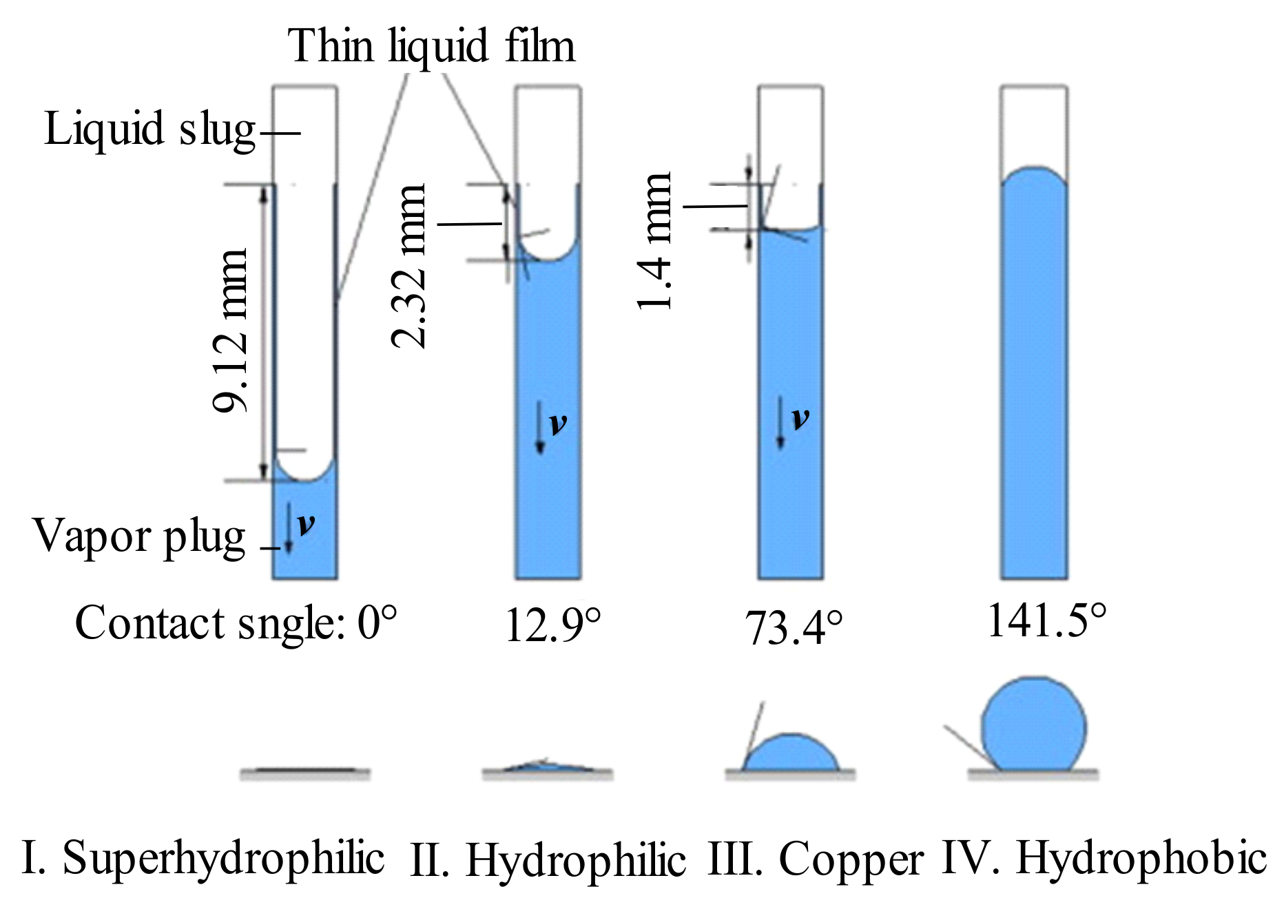
- Wang, J.; Xie, J.; Liu, X. Investigation of wettability on performance of pulsating heat pipe. Int. J. Heat Mass Transf. 2020, 150, 119354. [Google Scholar] [CrossRef]
- Lin, Z.; Wang, S.; Chen, J.; Huo, J.; Hu, Y.; Zhang, W. Experimental study on effective range of miniature oscillating heat pipes. Appl. Therm. Eng. 2011, 31, 880–886. [Google Scholar] [CrossRef]
- Xian, H.; Xu, W.; Zhang, Y.; Du, X.; Yang, Y. Thermal characteristics and flow patterns of oscillating heat pipe with pulse heating. Int. J. Heat Mass Transf. 2014, 79, 332–341. [Google Scholar] [CrossRef]
- Zhao, J.; Jiang, W.; Liu, C.; Rao, Z. Thermal performance enhancement of an oscillating heat pipe with external expansion structure for thermal energy recovery and storage. Appl. Therm. Eng. 2019, 155, 667–675. [Google Scholar] [CrossRef]
- Taft, B.S.; Rhodes, M. Experimental investigation of oscillating heat pipes under direct current and pulse width modulation heating input conditions. Appl. Therm. Eng. 2017, 126, 1018–1022. [Google Scholar] [CrossRef]
- Chu, L.; Ji, Y.; Liu, Z.; Yu, C.; Wu, Z.; Wang, Z.; Yang, Y.; Yang, X. Structure optimization of a three-dimensional coil oscillating heat pipe. Int. J. Heat Mass Transf. 2022, 183, 122229. [Google Scholar] [CrossRef]
- Chen, X.; Chen, S.; Zhang, Z.; Sun, D.; Liu, X. Heat transfer investigation of a flat-plate oscillating heat pipe with tandem dual channels under nonuniform heating. Int. J. Heat Mass Transf. 2021, 180, 121830. [Google Scholar] [CrossRef]
- Mangini, D.; Mameli, M.; Fioriti, D.; Filippeschi, S.; Araneo, L.; Marengo, M. Hybrid pulsating heat pipe for space applications with non-uniform heating patterns: Ground and microgravity experiments. Appl. Therm. Eng. 2017, 126, 1029–1043. [Google Scholar] [CrossRef]
- Peng, H.; Pai, P.F.; Ma, H. Nonlinear thermomechanical finite-element modeling, analysis and characterization of multi-turn oscillating heat pipes. Int. J. Heat Mass Transf. 2014, 69, 424–437. [Google Scholar] [CrossRef]
- Qu, J.; Zhao, J.; Rao, Z. Experimental investigation on thermal performance of multi-layers three-dimensional oscillating heat pipes. Int. J. Heat Mass Transf. 2017, 115, 810–819. [Google Scholar] [CrossRef]
- Yasuda, Y.; Nabeshima, F.; Horiuchi, K.; Nagai, H. Visualization of the working fluid in a flat-plate pulsating heat pipe by neutron radiography. Int. J. Heat Mass Transf. 2022, 185, 122336. [Google Scholar] [CrossRef]
- Lim, J.; Kim, S.J. A channel layout of a micro pulsating heat pipe for an excessively localized heating condition. Appl. Therm. Eng. 2021, 196, 117266. [Google Scholar] [CrossRef]
- Jiaqiang, E.; Zhao, X.; Deng, Y.; Zhu, H. Pressure distribution and flow characteristics of closed oscillating heat pipe during the starting process at different vacuum degrees. Appl. Therm. Eng. 2016, 93, 166–173. [Google Scholar]
- Kharangate, C.R.; Mudawar, I. Review of computational studies on boiling and condensation. Int. J. Heat Mass Transf. 2017, 108, 1164–1196. [Google Scholar] [CrossRef]
- Tanguy, S.; Sagan, M.; Lalanne, B.; Couderc, F.; Colin, C. Benchmarks and numerical methods for the simulation of boiling flows. J. Comput. Phys. 2014, 264, 1–22. [Google Scholar] [CrossRef]
- Magnini, M.; Pulvirenti, B.; Thome, J. Numerical investigation of hydrodynamics and heat transfer of elongated bubbles during flow boiling in a microchannel. Int. J. Heat Mass Transf. 2013, 59, 451–471. [Google Scholar] [CrossRef]
- Barba, M.; Bruce, R.; Baudouy, B. Numerical simulation of the thermal and fluid-dynamic behavior of a cryogenic capillary tube. Cryogenics 2020, 106, 103044. [Google Scholar] [CrossRef]
- Nuntaphan, A.; Vithayasai, S.; Vorayos, N.; Vorayos, N.; Kiatsiriroat, T. Use of oscillating heat pipe technique as extended surface in wire-on-tube heat exchanger for heat transfer enhancement. Int. Commun. Heat Mass Transf. 2010, 37, 287–292. [Google Scholar] [CrossRef]
- Qian, N.; Wang, X.; Fu, Y.; Zhao, Z.; Xu, J.; Chen, J. Predicting heat transfer of oscillating heat pipes for machining processes based on extreme gradient boosting algorithm. Appl. Therm. Eng. 2020, 164, 114521. [Google Scholar] [CrossRef]
- Sun, Q.; Qu, J.; Wang, Q.; Yuan, J. Operational characteristics of oscillating heat pipes under micro-gravity condition. Int. Commun. Heat Mass Transf. 2017, 88, 28–36. [Google Scholar] [CrossRef]
- Nemati, R.; Shafii, M.B. Advanced heat transfer analysis of a U-shaped pulsating heat pipe considering evaporative liquid film trailing from its liquid slug. Appl. Therm. Eng. 2018, 138, 475–489. [Google Scholar] [CrossRef]
- Daimaru, T.; Nagai, H.; Ando, M.; Tanaka, K.; Okamoto, A.; Sugita, H. Comparison between numerical simulation and on-orbit experiment of oscillating heat pipes. Int. J. Heat Mass Transf. 2017, 109, 791–806. [Google Scholar]
- Adachi, T.; Fujita, K.; Nagai, H. Numerical study of temperature oscillation in loop heat pipe. Appl. Therm. Eng. 2019, 163, 114281. [Google Scholar] [CrossRef]
- Odagiri, K.; Wolk, K.; Cappucci, S.; Morellina, S.; Roberts, S.; Pate, A.; Furst, B.; Sunada, E.; Daimaru, T. Three-dimensional heat transfer analysis of flat-plate oscillating heat pipes. Appl. Therm. Eng. 2021, 195, 117189. [Google Scholar] [CrossRef]
- Jahan, S.A.; Ali, M.; Islam, M.Q. Effect of inclination angles on heat transfer characteristics of a closed loop pulsating heat pipe. Procedia Eng. 2013, 56, 82–87. [Google Scholar] [CrossRef]
- Mameli, M.; Araneo, L.; Filippeschi, S.; Marelli, L.; Testa, R.; Marengo, M. Thermal response of a closed loop pulsating heat pipe under a varying gravity force. Int. J. Therm. Sci. 2014, 80, 11–22. [Google Scholar] [CrossRef]
- Mameli, M.; Manno, V.; Filippeschi, S.; Marengo, M. Thermal instability of a Closed Loop Pulsating Heat Pipe: Combined effect of orientation and filling ratio. Exp. Therm. Fluid Sci. 2014, 59, 222–229. [Google Scholar] [CrossRef]
- Ayel, V.; Araneo, L.; Scalambra, A.; Mameli, M.; Romestant, C.; Piteau, A.; Marengo, M.; Filippeschi, S.; Bertin, Y. Experimental study of a closed loop flat plate pulsating heat pipe under a varying gravity force. Int. J. Therm. Sci. 2015, 96, 23–34. [Google Scholar] [CrossRef]
- Mangini, D.; Mameli, M.; Georgoulas, A.; Araneo, L.; Filippeschi, S.; Marengo, M. A pulsating heat pipe for space applications: Ground and microgravity experiments. Int. J. Therm. Sci. 2015, 95, 53–63. [Google Scholar] [CrossRef]
- Cecere, A.; De Cristofaro, D.; Savino, R.; Ayel, V.; Sole-Agostinelli, T.; Marengo, M.; Romestant, C.; Bertin, Y. Experimental analysis of a flat plate pulsating heat pipe with self-rewetting fluids during a parabolic flight campaign. Acta Astronaut. 2018, 147, 454–461. [Google Scholar] [CrossRef]
- Xing, M.; Wang, R.; Yu, J. The impact of gravity on the performance of pulsating heat pipe using surfactant solution. Int. J. Heat Mass Transf. 2020, 151, 119466. [Google Scholar] [CrossRef]
- Pagliarini, L.; Cattani, L.; Bozzoli, F.; Mameli, M.; Filippeschi, S.; Rainieri, S.; Marengo, M. Thermal characterization of a multi-turn pulsating heat pipe in microgravity conditions: Statistical approach to the local wall-to-fluid heat flux. Int. J. Heat Mass Transf. 2021, 169, 120930. [Google Scholar] [CrossRef]
- Lv, Y.; Xia, G.; Cheng, L.; Ma, D. Experimental investigation into unstable two phase flow phenomena during flow boiling in multi-microchannels. Int. J. Therm. Sci. 2021, 166, 106985. [Google Scholar] [CrossRef]
- Yuan, D.; Qu, W.; Ma, T. Flow and heat transfer of liquid plug and neighboring vapor slugs in a pulsating heat pipe. Int. J. Heat Mass Transf. 2010, 53, 1260–1268. [Google Scholar] [CrossRef]
- Karthikeyan, V.K.; Khandekar, S.; Pillai, B.C.; Sharma, P.K. Infrared thermography of a pulsating heat pipe: Flow regimes and multiple steady states. Appl. Therm. Eng. 2014, 62, 470–480. [Google Scholar] [CrossRef]
- Spinato, G.; Borhani, N.; D’Entremont, B.P.; Thome, J.R. Time-strip visualization and thermo-hydrodynamics in a Closed Loop Pulsating Heat Pipe. Appl. Therm. Eng. 2015, 78, 364–372. [Google Scholar] [CrossRef]
- Xian, H.; Xu, W.; Zhang, Y.; Du, X.; Yang, Y. Experimental investigations of dynamic fluid flow in oscillating heat pipe under pulse heating. Appl. Therm. Eng. 2015, 88, 376–383. [Google Scholar] [CrossRef]
- Pouryoussefi, S.M.; Zhang, Y. Numerical investigation of chaotic flow in a 2D closed-loop pulsating heat pipe. Appl. Therm. Eng. 2016, 98, 617–627. [Google Scholar] [CrossRef]
- Feldmann, D.; Wagner, C. On the influence of computational domain length on turbulence in oscillatory pipe flow. Int. J. Heat Fluid Flow 2016, 61, 229–244. [Google Scholar] [CrossRef]
- Pouryoussefi, S.M.; Zhang, Y. Analysis of chaotic flow in a 2D multi-turn closed-loop pulsating heat pipe. Appl. Therm. Eng. 2017, 126, 1069–1076. [Google Scholar] [CrossRef]
- Mangini, D.; Marengo, M.; Araneo, L.; Mameli, M.; Fioriti, D.; Filippeschi, S. Infrared analysis of the two phase flow in a single closed loop pulsating heat pipe. Exp. Therm. Fluid Sci. 2018, 97, 304–312. [Google Scholar] [CrossRef]
- Xia, G.; Lv, Y.; Cheng, L.; Ma, D.; Jia, Y. Experimental study and dynamic simulation of the continuous two-phase instable boiling in multiple parallel microchannels. Int. J. Heat Mass Transf. 2019, 138, 961–984. [Google Scholar] [CrossRef]
- Yoon, A.; Kim, S.J. Experimental and theoretical studies on oscillation frequencies of liquid slugs in micro pulsating heat pipes. Energy Convers. Manag. 2019, 181, 48–58. [Google Scholar] [CrossRef]
- Ling, Y.Z.; Zhang, X.S.; Wang, X. Study of flow characteristics of an oscillating heat pipe. Appl. Therm. Eng. 2019, 160, 113995. [Google Scholar] [CrossRef]
- Noh, H.Y.; Kim, S.J. Numerical simulation of pulsating heat pipes: Parametric investigation and thermal optimization. Energy Convers. Manag. 2020, 203, 112237. [Google Scholar] [CrossRef]
- Ahmad, H.; Kim, S.K.; Jung, S.Y. Analysis of thermally driven flow behaviors for two-turn closed-loop pulsating heat pipe in ambient conditions: An experimental approach. Int. J. Heat Mass Transf. 2020, 150, 119245. [Google Scholar] [CrossRef]
- Vo, D.T.; Kim, H.T.; Ko, J.; Bang, K.H. An experiment and three-dimensional numerical simulation of pulsating heat pipes. Int. J. Heat Mass Transf. 2020, 150, 119317. [Google Scholar] [CrossRef]
- Schwarz, F.; Uddehal, S.R.; Lodermeyer, A.; Bagheri, E.M.; Forster-Heinlein, B.; Becker, S. Interaction of flow pattern and heat transfer in oscillating heat pipes for hot spot applications. Appl. Therm. Eng. 2021, 196, 117334. [Google Scholar] [CrossRef]
- Rao, M.; Lefèvre, F.; Czujko, P.-C.; Khandekar, S.; Bonjour, J. Numerical and experimental investigations of thermally induced oscillating flow inside a capillary tube. Int. J. Therm. Sci. 2017, 115, 29–42. [Google Scholar] [CrossRef]
- Yoon, A.; Kim, S.J. Characteristics of oscillating flow in a micro pulsating heat pipe: Fundamental-mode oscillation. Int. J. Heat Mass Transf. 2017, 109, 242–253. [Google Scholar] [CrossRef]
- Spinato, G.; Borhani, N.; Thome, J.R. Understanding the self-sustained oscillating two-phase flow motion in a closed loop pulsating heat pipe. Energy 2015, 90, 889–899. [Google Scholar] [CrossRef]
- Dilawar, M.; Pattamatta, A. A parametric study of oscillatory two-phase flows in a single turn Pulsating Heat Pipe using a non-isothermal vapor model. Appl. Therm. Eng. 2013, 51, 1328–1338. [Google Scholar] [CrossRef]
- Kato, S.; Okuyama, K.; Ichikawa, T.; Mori, S. A single, straight-tube pulsating heat pipe (examination of a mechanism for the enhancement of heat transport). Int. J. Heat Mass Transf. 2013, 64, 254–262. [Google Scholar] [CrossRef]
- Miura, M.; Nagasaki, T.; Ito, Y. Experimental study on heat transport induced by phase changes associated with liquid column oscillation in pulsating heat pipes. Int. J. Heat Mass Transf. 2019, 133, 652–661. [Google Scholar] [CrossRef]
- Daimaru, T.; Yoshida, S.; Nagai, H. Study on thermal cycle in oscillating heat pipes by numerical analysis. Appl. Therm. Eng. 2017, 113, 1219–1227. [Google Scholar] [CrossRef]
- Das, S.P.; Nikolayev, V.S.; Lefèvre, F.; Pottier, B.; Khandekar, S.; Bonjour, J. Thermally induced two-phase oscillating flow inside a capillary tube. Int. J. Heat Mass Transf. 2010, 53, 3905–3913. [Google Scholar] [CrossRef]
- Jung, C.; Kim, S.J. Effects of oscillation amplitudes on heat transfer mechanisms of pulsating heat pipes. Int. J. Heat Mass Transf. 2021, 165, 120642. [Google Scholar] [CrossRef]
- Sarangi, R.K.; Swain, A.; Kar, S.P.; Sekhar, P.C. Modeling for liquid plug oscillation frequency and amplitude of Pulsating heat pipe. Mater. Today Proc. 2022, 49, 372–377. [Google Scholar] [CrossRef]
- Pai, P.F.; Peng, H.; Ma, H. Thermomechanical finite-element analysis and dynamics characterization of three-plug oscillating heat pipes. Int. J. Heat Mass Transf. 2013, 64, 623–635. [Google Scholar] [CrossRef]
- Perna, R.; Abela, M.; Mameli, M.; Mariotti, A.; Pietrasanta, L.; Marengo, M.; Filippeschi, S. Flow characterization of a pulsating heat pipe through the wavelet analysis of pressure signals. Appl. Therm. Eng. 2020, 171, 115128. [Google Scholar] [CrossRef]
- Recklin, V.; Pattamatta, A.; Stephan, P. Experimental investigation on the thermo-hydrodynamics of oscillatory meniscus in a capillary tube using FC-72 as working fluid. Int. J. Multiph. Flow 2015, 75, 82–87. [Google Scholar] [CrossRef]
- Rao, M.; Lefèvre, F.; Khandekar, S.; Bonjour, J. Understanding transport mechanism of a self-sustained thermally driven oscillating two-phase system in a capillary tube. Int. J. Heat Mass Transf. 2013, 65, 451–459. [Google Scholar] [CrossRef]
- Rao, M.; Lefèvre, F.; Khandekar, S.; Bonjour, J. Heat and mass transfer mechanisms of a self-sustained thermally driven oscillating liquid–vapour meniscus. Int. J. Heat Mass Transf. 2015, 86, 519–530. [Google Scholar] [CrossRef]
- Fourgeaud, L.; Nikolayev, V.S.; Ercolani, E.; Duplat, J.; Gully, P. In situ investigation of liquid films in pulsating heat pipe. Appl. Therm. Eng. 2017, 126, 1023–1028. [Google Scholar] [CrossRef]
- Jiaqiang, E.; Zhao, X.; Liu, H.; Chen, J.; Zuo, W.; Peng, Q. Field synergy analysis for enhancing heat transfer capability of a novel narrow-tube closed oscillating heat pipe. Appl. Energy 2016, 175, 218–228. [Google Scholar] [CrossRef]
- Ando, M.; Okamoto, A.; Tanaka, K.; Maeda, M.; Sugita, H.; Daimaru, T.; Nagai, H. On-orbit demonstration of oscillating heat pipe with check valves for space application. Appl. Therm. Eng. 2018, 130, 552–560. [Google Scholar] [CrossRef]
- Mito, T.; Natsume, K.; Yanagi, N.; Tamura, H.; Tamada, T.; Shikimachi, K.; Hirano, N.; Nagaya, S. Achievement of high heat removal characteristics of superconducting magnets with imbedded oscillating heat pipes. IEEE Trans. Appl. Supercond. 2011, 21, 2470–2473. [Google Scholar] [CrossRef]
- Shi, W.; Li, W.; Pan, L.; Tan, X. Heat transfer properties and chaotic analysis of parallel type pulsating heat pipe. Trans. Tianjin Univ. 2011, 17, 435–439. [Google Scholar] [CrossRef]
- Zhao, J.; Rao, Z.; Liu, C.; Li, Y. Experiment study of oscillating heat pipe and phase change materials coupled for thermal energy storage and thermal management. Int. J. Heat Mass Transf. 2016, 99, 252–260. [Google Scholar] [CrossRef]
- Qu, J.; Wang, C.; Li, X.; Wang, H. Heat transfer performance of flexible oscillating heat pipes for electric/hybrid-electric vehicle battery thermal management. Appl. Therm. Eng. 2018, 135, 1–9. [Google Scholar] [CrossRef]
- Zhao, J.; Jiang, W.; Rao, Z. Thermal performance investigation of an oscillating heat pipe with external expansion structure used for thermal energy recovery and storage. Int. J. Heat Mass Transf. 2019, 132, 920–928. [Google Scholar] [CrossRef]
- Saha, N.; Das, P.K.; Sharma, P.K. Influence of process variables on the hydrodynamics and performance of a single loop pulsating heat pipe. Int. J. Heat Mass Transf. 2014, 74, 238–250. [Google Scholar] [CrossRef]
- Senjaya, R.; Inoue, T. Oscillating heat pipe simulation considering bubble generation Part II: Effects of fitting and design parameters. Int. J. Heat Mass Transf. 2013, 60, 825–835. [Google Scholar] [CrossRef]
- Lips, S.; Bensalem, A.; Bertin, Y.; Ayel, V.; Romestant, C.; Bonjour, J. Experimental evidences of distinct heat transfer regimes in pulsating heat pipes (PHP). Appl. Therm. Eng. 2010, 30, 900–907. [Google Scholar] [CrossRef]
- Sun, Q.; Qu, J.; Yuan, J.; Wang, Q. Operational characteristics of an MEMS-based micro oscillating heat pipe. Appl. Therm. Eng. 2017, 124, 1269–1278. [Google Scholar] [CrossRef]
- Nikolayev, V.S. Effect of tube heat conduction on the single branch pulsating heat pipe start-up. Int. J. Heat Mass Transf. 2016, 95, 477–487. [Google Scholar] [CrossRef]
- Pandey, H.; Agarwal, S.; Gupta, N.K. Temporal performance evaluation of CuO + GO hybrid nanofluids in heat pipe. Heat Transf. Res. 2022, 53, 75–96. [Google Scholar] [CrossRef]
- Abbasi, A.; Al-Khaled, K.; Khan, M.I.; Khan, S.U.; El-Refaey, A.M.; Farooq, W.; Jameel, M.; Qayyum, S. Optimized analysis and enhanced thermal efficiency of modified hybrid nanofluid (Al2O3, CuO, Cu) with nonlinear thermal radiation and shape features. Case Stud. Therm. Eng. 2021, 28, 101425. [Google Scholar] [CrossRef]
- Shanmugapriya, M.; Sundareswaran, R.; Kumar, P.S. Heat and Mass Transfer Enhancement of MHD Hybrid Nanofluid Flow in the Presence of Activation Energy. Int. J. Chem. Eng. 2021, 2021, 9473226. [Google Scholar] [CrossRef]
- Rao, Z.; Wang, Q.; Zhao, J.; Huang, C. Experimental investigation on the thermal performance of a closed oscillating heat pipe in thermal management. Heat Mass Transf. 2017, 53, 3059–3071. [Google Scholar] [CrossRef]
- Zamani, R.; Kalan, K.; Shafii, M.B. Experimental investigation on thermal performance of closed loop pulsating heat pipes with soluble and insoluble binary working fluids and a proposed correlation. Heat Mass Transf. 2018, 55, 375–384. [Google Scholar] [CrossRef]
- Ayel, V.; Slobodeniuk, M.; Bertossi, R.; Karmakar, A.; Martineau, F.; Romestant, C.; Bertin, Y.; Khandekar, S. Thermal performances of a flat-plate pulsating heat pipe tested with water, aqueous mixtures and surfactants. Int. J. Therm. Sci. 2022, 178, 107599. [Google Scholar] [CrossRef]
- Rho, H.; Lee, S.; Bae, S.; Kim, T.W.; Lee, D.S.; Lee, H.J.; Hwang, J.Y.; Jeong, T.; Kim, S.; Ha, J.S.; et al. Three-Dimensional Porous Copper-Graphene Heterostructures with Durability and High Heat Dissipation Performance. Sci. Rep. 2015, 5, 12710. [Google Scholar] [CrossRef]
- Malla, L.K.; Dhanalakota, P.; Mahapatra, P.S.; Pattamatta, A. Thermal and flow characteristics in a flat plate pulsating heat pipe with ethanol-water mixtures: From slug-plug to droplet oscillations. Int. J. Heat Mass Transf. 2022, 194, 123066. [Google Scholar] [CrossRef]
- Li, Q.; Wang, C.; Wang, Y.; Wang, Z.; Li, H.; Lian, C. Study on the effect of the adiabatic section parameters on the performance of pulsating heat pipes. Appl. Therm. Eng. 2020, 180, 115813. [Google Scholar] [CrossRef]
- Błasiak, P.; Opalski, M.; Parmar, P.; Czajkowski, C.; Pietrowicz, S. The Thermal—Flow Processes and Flow Pattern in a Pulsating Heat Pipe—Numerical Modelling and Experimental Validation. Energies 2021, 14, 5952. [Google Scholar] [CrossRef]
- Zhao, J.; Wu, C.; Rao, Z. Numerical study on heat transfer enhancement of closed loop oscillating heat pipe through active incentive method. Int. Commun. Heat Mass Transf. 2020, 115, 104612. [Google Scholar] [CrossRef]
- Dreiling, R.; Dubois, V.; Zimmermann, S.; Nguyen-Xuan, T.; Schreivogel, P.; di Mare, F. Numerical investigation of slug flow in pulsating heat pipes using an interface capturing approach. Int. J. Heat Mass Transf. 2022, 199, 123459. [Google Scholar] [CrossRef]
- Wang, X.; Yan, Y.; Meng, X.; Chen, G. A general method to predict the performance of closed pulsating heat pipe by artificial neural network. Appl. Therm. Eng. 2019, 157, 113761. [Google Scholar] [CrossRef]
- Jalilian, M.; Kargarsharifabad, H.; Abbasi Godarzi, A.; Ghofrani, A.; Shafii, M.B. Simulation and optimization of pulsating heat pipe flat-plate solar collectors using neural networks and genetic algorithm: A semi-experimental investigation. Clean Technol. Environ. Policy 2016, 18, 2251–2264. [Google Scholar] [CrossRef]
- Wen, J. Thermal resistance modeling of oscillating heat pipes filled with acetone by using artificial neural network. J. Therm. Anal. Calorim. 2021, 144, 1873–1881. [Google Scholar] [CrossRef]
- Jokar, A.; Godarzi, A.A.; Saber, M.; Shafii, M.B. Simulation and optimization of a pulsating heat pipe using artificial neural network and genetic algorithm. Heat Mass Transf. 2016, 52, 2437–2445. [Google Scholar] [CrossRef]


| Metal Nano-Category | Particle Size | Concentration | Liquid Filling Rate | Inclination Angle/° | Heating Power/W | Reduction of Thermal Resistance |
|---|---|---|---|---|---|---|
| Al2O3 [68] | − | 0, 0.1, and 0.5 wt.% | 50% | 0, 90 | 10~80 | 15.8% |
| Al2O3 [69] | 56 nm | 0~1.2 wt.% | 50% | 90 | 20~140 | 25.7% |
| Ag [70] | 50 nm | 50, 200, and 600 ppm | − | − | 314, 385, and 488 | 30% |
| Al2O3 [71] | 10~30 | 0.5, 1, and 3 wt.% | 20%, 40%, 60%, and 80% | 10, 40, 70, and 90 | 20, 30, and 40 | Improved thermal performance by 56.3% |
| ɤ-Fe2O3 [72] | 20 | 2 vol.% | 50% | 90 | 0~160 | 12% |
| Fe2O3 [73] | 20 | 2 vol.% | 50% | 0~90 | 10~90 | 24.1% |
| Fe3O4 [74] | 5~20 | 90, 270, and 450 ppm | 70% | 90 | 20, 55, 90, 125, and 160 | 27.6% |
| Fe3O4 [75] | 25 | 0.2 wt.% | 50% | 90 | 0~200 | 11% |
| NiFe2O4 [76] | 25 | 1.5, 3 wt.% | − | 90 | 200, 300, and 400 | 30.4% |
| Non-Metallic Nano-Fluids | Concentration | Liquid Filling Rate/% | Inclination Angle/° | Input Power/W | Reduction of Thermal Resistance |
|---|---|---|---|---|---|
| MWCNTs [84] | 0.05, 0.1, 0.2, and 0.3 wt.% | 60 | 90 | 50 ~400 | About 36.2% |
| Graphene [85] | 0.025, 0.05, 0.075, and 0.1 wt.% | − | 0~90 | 20~120 | 48.4% |
| Graphene oxide (GO) [86] | 0.01 and 0.03 vol.% | 100 | 90 | 50 ~400 | Maximum heat transfer enhancement 25% |
| C60 [87] | 0.1, 0.2, and 0.3 wt.% | 50 | 50 | 10~60 | 36% |
| Hydroxylation MWNTs [88] | 0.1~1 wt.% | 50 | 90 | – | 34% |
| Graphene Nano-sheets [89] | 1.2, 2, 5.7, 9.1, 13.8, and 16.7 vol.% | 45, 55, 62, 70, and 90 | 90 | 10 ~100 | 83.6% |
| Graphene oxide [90] | 0.25, 0.5, 1, and 1.5 g/L | 50 | 90 | 10~70 | 42% |
| Oligographene (FLG) [91] | 0.1, 0.3, 0.5, 0.75, and 1 mg/mL | 55 | 90 | 20~60 | 25.16% |
| Carbon nano-tubes (CNTs) [92] | 0.05, 0.1, 0.2, 0.3, and 0.5 wt.% | 35 | 90 | 8~56 | About 66.6% |
| Graphene oxide [93] | 0.02~0.1 wt.% | 20, 50, and 80 | 90 | 10~30 | 54.34% |
| SiO2 [94] | 0.5, 1, 1.5, and 2 wt.% | 50 | 90 | 10~50 | 40.1% |
| Working Fluids | Filling Rate/% | Input Power/W | Lowest Thermal Resistance/°C·W−1 | Lowest Thermal Resistance Obtained |
|---|---|---|---|---|
| Ethanol [122] | 0, 25, 37.5, 50, 62.5, 75, and 100 | – | 0.95 | 50% |
| Methanol [123] | 20~95 | 5~100 | 0.2 | 95% and 100 W |
| Ethanol [124] | 50 | 15~50 | 0.6244 | 50 W |
| Acetone [125] | 50 ± 5% and 70 ± 5% | 60~300 | 0.092 | 70% and 260 W |
| Lonic liquids [126] | 65 ± 5 | 50~250 | 0.15 | 44.4% and 250 W |
| Acetone [127] | 50 | 10~200 | 0.14 | 200 W |
| LiCl solution [128] | 45, 55, 62, 70, 80, and 90 | 10~100 | 0.9 | 62% and 10 wt.% |
| Acetone [129] | 0~100 | 10~120 | 0.39 | 60% and 100 W |
| R1233zd(E) [130] | 40~70 | 0~200 | 0.1184 | 50% and 70 W |
| Content | Remarks |
|---|---|
| Energy jump conditions [179] | is the phase change local mass flow rate, kg/(m3·s). Lv is latent heat. cp,v is constant pressure specific heat of vapor, J/(kg·K). Tsat is the saturation temperature associated with the considered pressure, K. Tint is the local interface temperature, K. klv is thermal conductivity, W/(m·K). is the normal vector pointing in the direction of the gas phase at the Γ of the interface. |
| Tanasawa model [180] | γ is the adjustment factor. M is the molecular weight. Rg is a general gas constant. is 8.314 J/(mol K). ρv is the density of vapor, kg/m3. Tif is the interface temperature, K. |
| Lee model [181] | is the mass transfer of each time step in the evaporation process, kg/(m3·s). is the mass transfer of each time step in the condensation process, kg/(m3·s). αl and αv are the volume fraction of liquids and vapors. |
Disclaimer/Publisher’s Note: The statements, opinions and data contained in all publications are solely those of the individual author(s) and contributor(s) and not of MDPI and/or the editor(s). MDPI and/or the editor(s) disclaim responsibility for any injury to people or property resulting from any ideas, methods, instructions or products referred to in the content. |
© 2023 by the authors. Licensee MDPI, Basel, Switzerland. This article is an open access article distributed under the terms and conditions of the Creative Commons Attribution (CC BY) license (https://creativecommons.org/licenses/by/4.0/).
Share and Cite
Zhao, X.; Su, L.; Jiang, J.; Deng, W.; Zhao, D. A Review of Working Fluids and Flow State Effects on Thermal Performance of Micro-Channel Oscillating Heat Pipe for Aerospace Heat Dissipation. Aerospace 2023, 10, 179. https://doi.org/10.3390/aerospace10020179
Zhao X, Su L, Jiang J, Deng W, Zhao D. A Review of Working Fluids and Flow State Effects on Thermal Performance of Micro-Channel Oscillating Heat Pipe for Aerospace Heat Dissipation. Aerospace. 2023; 10(2):179. https://doi.org/10.3390/aerospace10020179
Chicago/Turabian StyleZhao, Xiaohuan, Limin Su, Jiang Jiang, Wenyu Deng, and Dan Zhao. 2023. "A Review of Working Fluids and Flow State Effects on Thermal Performance of Micro-Channel Oscillating Heat Pipe for Aerospace Heat Dissipation" Aerospace 10, no. 2: 179. https://doi.org/10.3390/aerospace10020179