Article

Prediction of the Propulsive Performance of an Atmosphere-Breathing Electric Propulsion System on Cathode-Less Plasma Thruster

1
Alma Propulsion Laboratory, Department of Industrial Engineering (DIN), University of Bologna, 47122 Forlì, Italy
2
Department of Information Engineering (DEI), University of Padova, 35131 Padova, Italy
*
Author to whom correspondence should be addressed.
These authors contributed equally to this work.
Aerospace 2023, 10(2), 100; https://doi.org/10.3390/aerospace10020100
Submission received: 31 December 2022 / Revised: 14 January 2023 / Accepted: 17 January 2023 / Published: 19 January 2023
(This article belongs to the Special Issue Aerospace Combustion Engineering)

Abstract

:
Atmosphere-breathing electric propulsion (ABEP) is a type of electric propulsion system that uses the atmosphere as a propellant source instead of a stored reservoir. This technology is still in its early stages, but holds the promise of providing a clean, efficient, and sustainable propulsion system for spacecraft, enabling very low Earth orbit (VLEO) mission scenarios. To optimise the ABEP technology, accurately simulating air-based plasma chemistry plays a crucial role. In this paper, an air-based global model (GM) is presented that includes a detailed chemistry model for the various reactions that are involved in ABEP applications. The model’s goal is to forecast the performance of a cathode-less RF plasma thruster under various pressure levels and species concentrations that are typical of VLEO missions. The GM was exploited to map the performance of a fictitious ABEP based on a cathode-less RF thruster in order to assess its feasibility in VLEO. The numerical model is promising as a tool for the design of ABEP systems and for the preliminary optimization of mission scenarios.

1. Introduction

The low Earth orbit (LEO), ranging from 160 up to 2000 km [1], represents the most crowded region around the Earth, mainly due to the great benefits that it can provide to a mission as a whole. The lowest part of LEO is usually referred to as very low Earth orbit (VLEO) and it consists of orbits below 450 km [2,3]. These orbits, much lower than the traditional LEO, are gaining increased attention due to their potential for a variety of applications, including high-resolution Earth observation, communications, and navigation [4]. VLEOs offer a number of advantages over traditional LEOs [2]. For example, satellites can provide higher-resolution imagery and communications due to their proximity to Earth’s surface. Additionally, VLEO satellites have shorter orbital periods and require less propellant to reach their orbits, resulting in lower launch and operating costs. Moreover, because of the increased air density in VLEO, any space debris that is produced there or reaches this regime from higher orbits would degrade more quickly [2], making the region safer for the life of the satellite. This, however, implies that a satellite or spacecraft is subjected to increased drag force as well. The spacecraft gradually slows down due to drag, causing the orbital altitude to drop. For orbits beyond VLEO, this issue is normally extremely limited, and the ensuing orbit decay is tolerable for the duration of the satellite’s operative life [5]. To prevent an orbit’s rapid decline, at lower altitude, the drag must be effectively counteracted by means of a propulsion system [6]. However, the thrust requirements for VLEO missions are quite a considerable obstacle in terms of both the stored propellant and thruster performance. To increase the capabilities of electric propulsion (EP) and render it useful in certain target orbits, the amount of on-board propellant must be decreased.
Atmosphere-breathing electric propulsion (ABEP), often referred to as RAM-EP, for satellites is an emerging technology that has the potential to revolutionise satellite operations. This type of propulsion system mainly uses residual air present in the atmosphere as a propellant source instead of traditional ones (e.g., xenon or krypton) to allow for satellites to maneuver and remain in orbit. This method results in a large reduction in onboard propellant, since plasma is created by using the particles ingested by the thruster intake. Depending on the type of cathode, it could still be necessary to carry an onboard reservoir [1]. Additionally, atmosphere-breathing propulsion systems are more environmentally friendly than chemical propellants, as they do not produce any harmful emissions [7].
In the last few years, several ABEP concepts have been developed all across the globe. At JAXA, Fujita [8,9] first proposed a thorough concept for an air-breathing ion thruster in 2004 with a focus on the creation of a suitable intake. The Air-breathing Electric THrustER (AETHER) project [10], funded by the European Commission under the H2020 program, intends to create the first propulsion system capable of keeping a spacecraft at VLEO altitudes for a sustained period of time. The major goal of the project is to illustrate in a realistic setting the vital roles played by an atmosphere-breathing electric propulsion system and how well it can counteract atmospheric drag. BUSEK led the primary research on atmosphere-breathing EP in the US for usage in a Martian environment, demonstrating the viability of Martian Atmosphere-Breathing Hall Effect Thruster (MABHET) [11]. To achieve this goal, BUSEK tested an unaltered Hall thruster (intended to run on xenon) with a gas combination primarily constituted by CO2, which is the main chemical species present in the Martian atmosphere. Recently, Romano et al. [12,13], from the University of Stuttgart, presented a concept for an RF helicon-based plasma thruster (IPT) within the DISCOVERER programme, a Horizon 2020 project whose goal is to innovate Earth observation satellites for long-term operations at significantly low-orbit altitudes [14].
In order to optimise the design of the aforementioned models, simulations of air-based plasma chemistry are carried out. Taploo et al. [15] produced a study on the ionisation process inside an ABEP in low Earth orbit applications (80–110 km), with the aim of removing the external neutraliser, hence decreasing design complexity. Mrozek et al. [16] presented the global plasma model of the laboratory model of a gridded atmosphere-breathing electric propulsion concept based on magnetised high-frequency plasma. An operating background pressure range was considered as well, allowing for the simulation of the performance within the range of 10−3 to 1 Pa. An investigation of an electron cyclotron resonance (ECR) plasma source for VLEO was carried out by Obrusnik et al. [17] by means of a global plasma model (GPM) for the absorbed power and a direct Monte Carlo (DSMC) simulation for the gas flow at the intake.
This work presents a description of an air-based global model (GM) containing a detailed chemical model for the several reactions that are involved in ABEP applications. The model is aimed at predicting the performance of a cathode-less RF plasma thruster (such as the helicon plasma thruster (HPT) [18]) at different altitudes (and hence different pressure levels and species concentrations). Atmospheric composition changes significantly with altitude; as a consequence, the importance of particular species and/or reactions may change depending on the orbit altitude. The GM was first used to predict the propulsive performance of an HPT [18,19,20,21], and compared to the same fed with iodine for which the GM had been validated in a previous work [22]. Lastly, the GM was exploited to predict the performance envelope of a fictitious cathode-less RF thruster targeted to work in atmosphere-breathing mode in order to show its capability and potential use for mission design in such scenarios.

2. Methodology

A cathode-less RF plasma thruster was taken into consideration in this work (refer to Figure 1). The newly developed global model (GM) based on [23,24,25,26] was used to forecast the population density for each species and the electron temperature within the source chamber. The GM takes into account the following hypotheses: (i) the magnetic field was assumed to be uniform and completely aligned with the thruster’s axis; (ii) the chamber was cylindrical with an open end for the exit; (iii) the influence of cusps was taken into account via empirical relations [27]. The plasma production was assumed to occur only within the cylindrical region of the source with an open end for the outlet; it had radius R , length L and volume V = π R 2 L . The dynamics of the plasma source were solved according to the conservation of mass (Equation (1)) for each species involved in the plasma, and electron energy (Equation (2)) equations:
d n I d t = R c h e m I R w a l l I R e x I + R i n I
d d t 3 2 n e T e = P R F P c h e m P w a l l P e x
where n I is the number density of species I. T e and n e are the electron temperature in eV and number density, respectively. For species I, R c h e m I is the source/sink term associated with plasma reactions, R w a l l I to wall losses, R e x I to particle outflow, and R i n I to particle inflow. P R F is the power coupled to the plasma, along with P c h e m being the source/sink term associated to plasma reactions, P w a l l to wall losses, and P e x to particle outflow. The chemical contributions can be written as follows [28]:
R c h e m I = J K J I n J n e J K I J n I n e
P c h e m = I J K I J n I n e Δ U I J + I K I I n I n e 3 m e m I T e
where K I J is the rate constant for the inelastic transitions from species I to species J, K I I is the rate constant for elastic collisions between species I and electrons, Δ U I J is the energy difference (in eV) between species I and species J, and m e and m I are the electron mass and the species I mass, respectively [29]. The terms related to wall losses (or production) can be evaluated by means of
R w a l l I = S w a l l I V Γ w a l l I
P w a l l = R w a l l e 2 + log m i 2 π m e T e
where V is the volume of the source, Γ I = n I u B ( u B being Bohm speed) is the particle flux, S I is an equivalent source surface for particle loss, and m i is the mass of ions. In order to use Equations (5) and (6), the Bohm sheath criterion at the source wall was also assumed to be the sonic condition at the thruster outlet [25]. Secondary electron emission was taken into account as well by means of the model employed in Zhou et al. [30].
We assumed that the neutrals were in the free-molecular regime, Γ g = 1 / 4 n g u t h , where u t h is the neutrals’ thermal speed [31] and n g is their number density. Regarding the exhaust contributions, R e x I and P e x read, respectively,
R e x I = S e x I V Γ e x I
P e x = R e x e 2 + log m i 2 π m e T e
For a closed cylinder with a nonuniform magnetic field (i.e., with cusps), S I can be accounted by means of
S I = 2 π R 2 h L β + h R ( 2 π R L S c u s p ) + h R S c u s p
where h R , h L and β are semiempirical coefficients [32,33,34] that account for the nonuniformity of the plasma profiles inside the source tube, and for the effect of electronegativity on the diffusion coefficients. According to Goebel et al. [27], the total cusp area can be evaluated as follows:
S c u s p = 4 N c u s p r c i r c e 2 π R
which can be interpreted as the equivalent area influenced by magnetic cusps [32]; N c u s p is the number of cusps present in the magnetic topology, and r c i and r c e are the ion and electron cyclotron radii, respectively.
Air-based plasma is composed by both positive and negative ions, and can be generally classified as electronegative plasma. In this case, the expression of h R and h L is: [16]
h L = 0.86 3 + L 2 λ + ( 1 + α ) 1 / 2 γ + 5 L λ 2 1 / 2
γ 1 γ ( 1 + α ) 2 + 1 γ 1 / 2 h R = 0.8 f b 4 + R λ + ( 1 + α ) 1 / 2 γ + R λ 2 1 / 2
γ 1 γ ( 1 + α ) 2 + 1 γ 1 / 2
where λ is the mean free path, α = n / n e is the electronegativity parameter, γ + and γ are the temperature ratios as described by Chabert [35], namely,
γ + = T + / T e
γ = T e / T
f b = ( 1 + ( ω τ ) 2 ) 1 , with ω being the cyclotron frequency and τ the mean free time.
The computation of diffusion parameters relies on the method of Lennard–Jones potentials, which provides an empirical description of the particles’ interatomic and intermolecular interactions.
When dealing with molecular plasma (e.g., iodine and air), a mixture-averaged approximation must be assumed in the computation of diffusion coefficient D for generic species I, with the aim of fully describing the diffusion of the species mixture:
D I = 1 Y I J I X I D I J
where X and Y are defined, respectively, by:
X I = n I n J
Y I = M I n I M J n J
M I and M J are the mass of species I-th and J-th, respectively, while n I and n J refer to their number density.

2.1. Plasma Chemistry

The composition of air, which is a combination of various gases, changes significantly with altitude. As a result, depending on the altitude at which the ABEP system is running, some species and/or reactions become more significant. Density fluctuation for the two primary species present in air, namely, oxygen and nitrogen, in both atomic (O, N) and molecular (O2, N2) forms, is illustrated in Figure 2 with respect to the altitude from sea level at a latitude of 38.91° and longitude of 77.04° [36]. Moreover, other species might be present within the plasma (e.g., NO), especially at denser altitudes, as a consequence of the heavy particle interaction [15].
Each reaction involving electrons (i.e., elastic scattering, ionisation, dissociation, dissociative attachment/detachment, and ionisation) has a different rate coefficient K that is evaluated by means of
K = 2 q m e 0 ε σ f 0 d ε
where q is the electron charge, ε is the electron energy in eV, and σ is the collision cross-section for the generic electron-particle reaction in m2. The electron energy distribution function (EEDF) f 0 was assumed to be Maxwellian [37], namely
f 0 ( ε ) = 2 1 T e 3 π exp ε T e
In this work, the considered species were electron, atomic, and molecular neutral species, namely, N, N2, O, O2, NO, N2O, NO2, excited state, and single-charged atomic and molecular ions. Regarding the chemistry model, the reactions that were included are elastic scattering, excitation, ionisation and neutralisation, molecular dissociation, attachment and detachment, dissociative neutralisation and ionisation, and charge exchange. The relevant reaction cross-sections can be found in [15,30,38].

2.2. Thrust Model

In order to predict the propulsive performance (i.e., thrust and specific impulse) of the thruster, the plume model from [39] was adopted. In order to use such a model, we assumed the following: (i) electron inertia is negligible; (ii) cold ion hypothesis [39,40]; (iii) ions and electrons leave the ionisation chamber at Bhom’s speed u B . The overall thrust can be then evaluated as
T = I ( F p I + F g a s I )
where for the I-th species (i.e., O, O2, N, etc.), F p I is the contribution of the plasma acceleration, and F g a s I is the force generated by the expansion of neutrals. The latter can be easily computed by means of
F g a s I = m ˙ I v I 1 + k B T g m I v I 2
where k B is the Boltzmann constant, m ˙ I is the ejected mass flow rate of the I-th species, T g is the neutral gas temperature in Kelvin, v I = γ k B T g / m I is the sound speed, and γ is the specific heat constant. Plasma acceleration term F p I is given via the combination of two terms:
F p I = F 0 I + F m a g I ,
namely, the contribution of source F 0 I and magnetic nozzle F m a g I . By assuming the paraxial approximation for the magnetic nozzle (i.e., B z ( r , z ) B z ( 0 , z ) ), from mass and momentum conservation [39,41], the magnetic nozzle term can be expressed as a function of F 0 I :
F m a g I = F 0 I ( M 1 ) 2 2 M
where M = v / u B is the magnetic Mach number (v is the plasma velocity). Considering the nozzle contribution up to the plasma detachment point allows for the evaluation of the overall thrust generated by plasma acceleration as follows:
F p I = F 0 I M d e t 2 + 1 2 M d e t
where M d e t is determined for each species according to [39]. Lastly, F 0 I can be expressed as follows [39]:
F 0 I = 2 β q n I T e A 0
where β is a dimensionless parameter that accounts for nonuniformity within the plasma, and A 0 is the outlet section of the thruster.
The specific impulse I s p can be evaluated as follows:
I s p = T g e m ˙ 0
where g e is the gravity acceleration constant at sea level, and m ˙ 0 the total mass flow rate.

3. Results

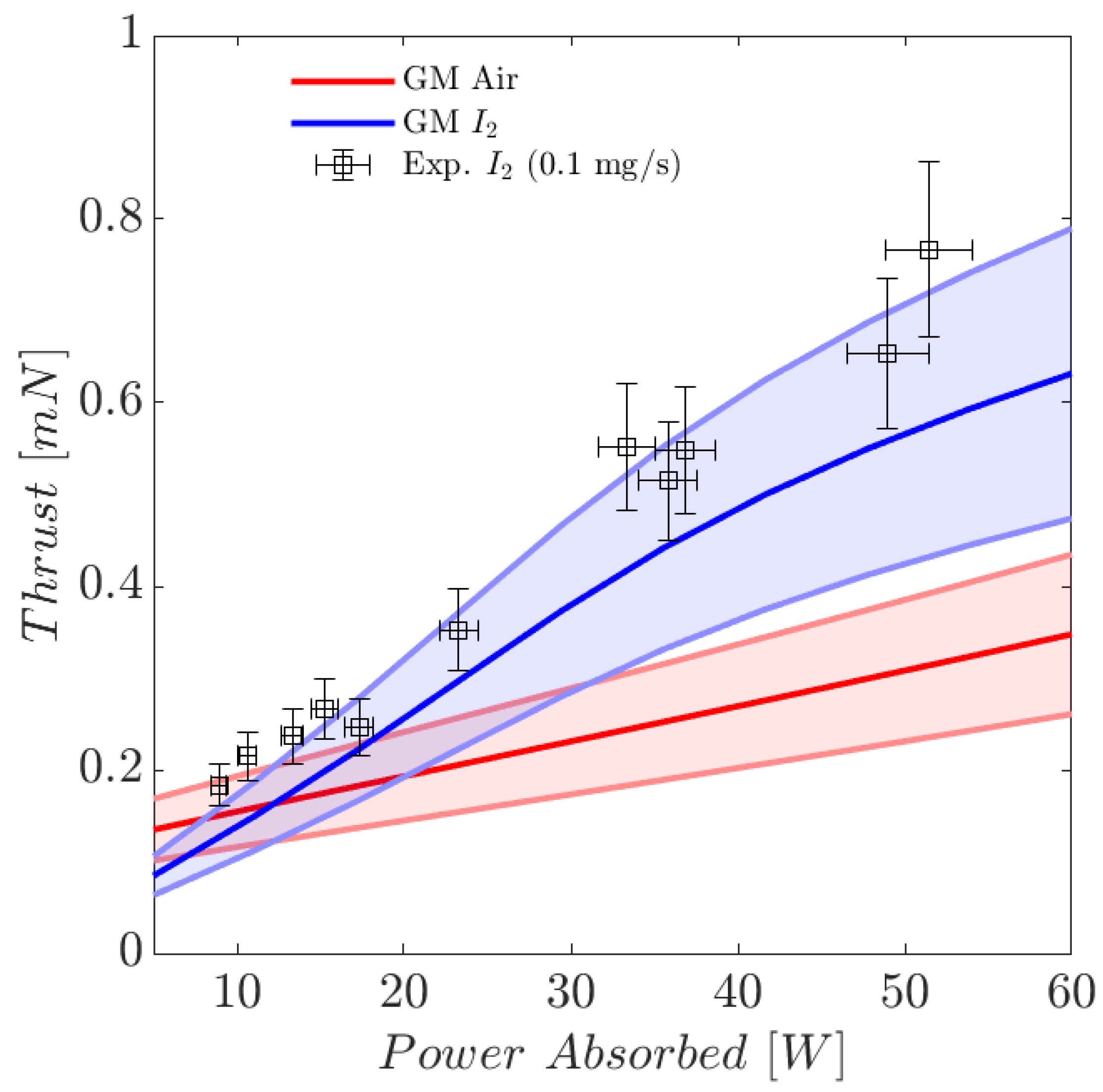
3.1. Comparison of the GM with Air and Iodine

To the authors’ knowledge, no detailed experimental measurements on ABEP have been applied to cathode-less thrusters at conditions representing different altitudes; hence, different chemical compositions of the atmosphere are present in the literature. Therefore, in order to provide a reasonable set of results, the outputs provided by the GM were first compared to the ones obtained with the same GM targeted at iodine propellant whose thrust prediction capability had been tested against the measurements of a helicon plasma thruster (HPT) [22,42]. Figure 3 shows the experimental thrust measurements of a laboratory model of an HPT [19,21] run on iodine. The thrust prediction obtained by the global model implementing the iodine chemistry model is presented as a function of the power absorbed by the plasma in the ionisation chamber and the one obtained for the air-based plasma. An uncertainty band of ±25% was attributed to the numerical results and was mainly associated to the assumptions (see Section 2) performed on the plasma profiles, the plasma–walls interaction, the cross-sections of the plasma reactions, and the detachment criterion in the propulsive model [23,25].
It is fairly reasonable to state that the GM was able to reproduce the overall thrust trend of the thruster, with the error being limited to a maximal value of ∼30%. The thrust profile predicted for air showed a different tendency, as more linear behaviour with respect to power could be observed. Moreover, the thrust produced with air was lower with respect to iodine. This reduced performance can be mainly attributed to the large number of mechanisms (e.g., dissociation, and recombination) that lead to the production of neutral species in the air. These reactions act as an energy sink and limit ionisation. Similarly, the multiple involved vibrational and rotative excitation modes contribute to reducing the overall available energy to produce and heat up plasma. The result is colder and less dense plasma, and hence poorer thruster performance (see Equation (24)).

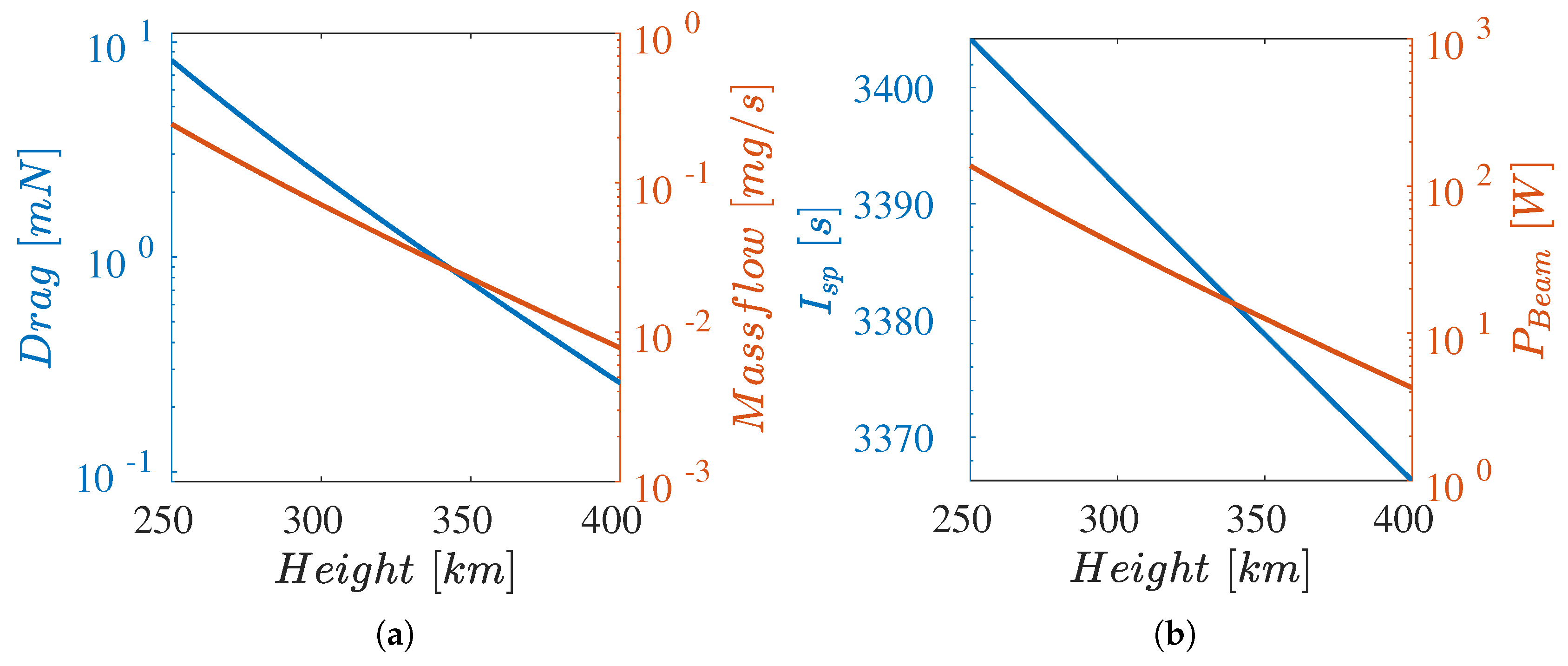
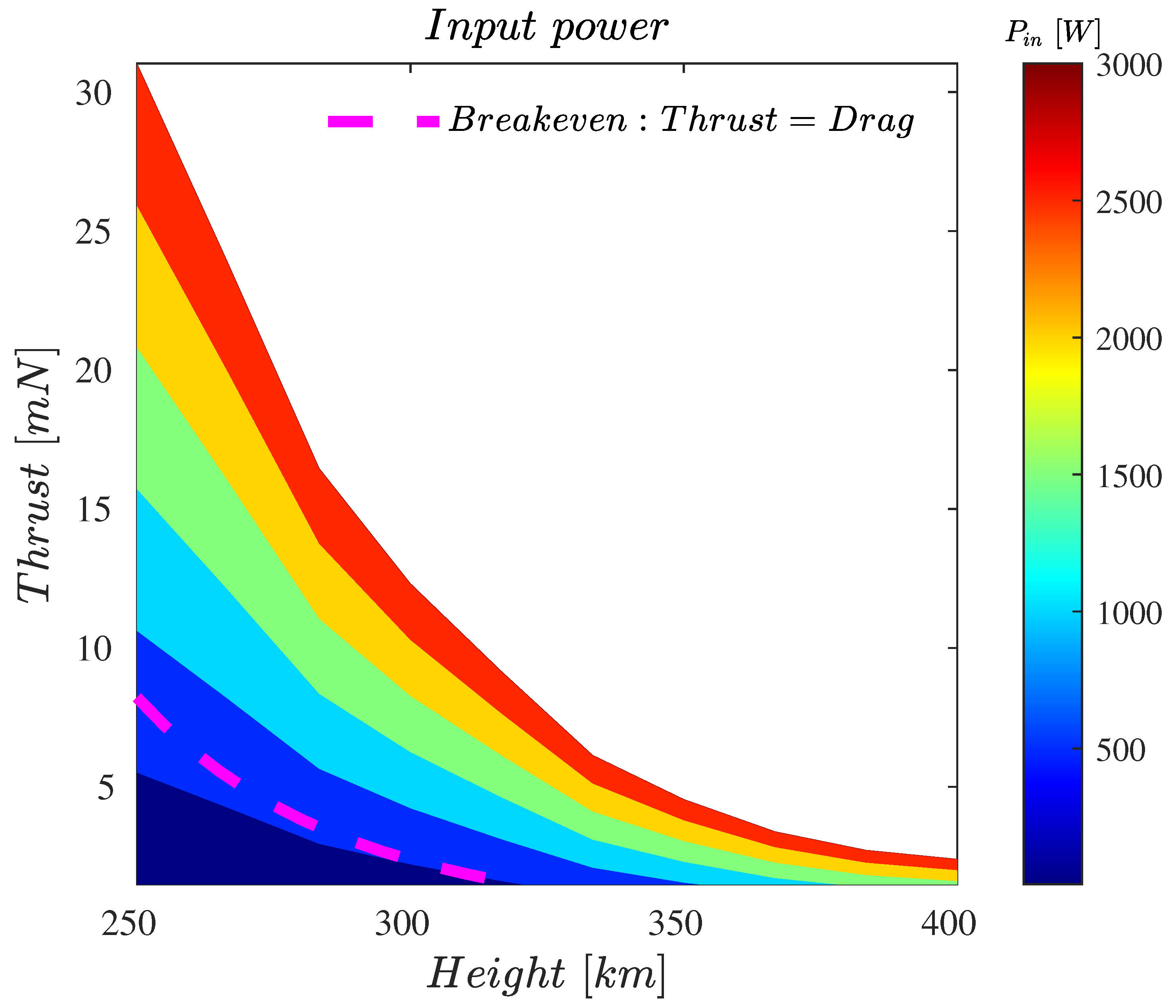
3.2. Feasibility Analysis of an ABEP Cathode-Less RF Plasma Thruster

The GM presented in Section 2 was exploited to test its potentiality as a tool for the mission assessment of an ABEP system based on cathode-less plasma thrusters. The considered scenario consisted in circular orbit maintenance in circular VLEO at orbital altitudes of 250–400 km [43]. The drag generated by the atmospheric residual particles to the spacecraft had to be compensated by the ABEP system during the whole operational time. In this analysis, a spacecraft similar to GOCE [44]) was considered. The spacecraft was equipped with an intake [45] responsible for collecting the atmospheric particles and funnelling them inside the thruster’s discharge chamber (see Figure 1).
In Table 1 the main parameters of the whole ABEP system are briefly reported. The considered intake is similar to the diffusive one described by Romano et al. [45], and a value of intake efficiency of η c = 0.43 was considered in accordance to the analysis proposed by Vaidya et al. [4]. The intake cross-sectional area A i n was assumed to be equal to the spacecraft’s frontal cross-section and the exit area A e x from the thruster’s outlet. An expansion ratio ϵ = 10 was considered between the intake (outlet) and the discharge chamber cross-section, and the spacecraft length was L = 1 m. The GOCE spacecraft drag coefficient ( C D = 3.7 ), which was derived from direct measurements, was considered [44] and assumed to be constant in the altitude range considered. Regarding the ABEP system, only configurations with a thruster efficiency of η t h r = 30 % or lower were considered, coherently to the state of the art [46]. A magnetic field of intensity up to B = 0.15 T , generated by three rings of permanent magnets, was assumed. In the following analysis, the input power P i n considered in the GM is antenna–plasma coupled power.
The drag force experienced by the spacecraft reads
D = 1 2 ρ A i n C D v o r b 2 ,
where ρ is the atmospheric density, and v o r b is the orbital velocity. For the sake of simplicity, the effects of atmospheric corotation and space weather were not taken into consideration. From Equation (26), the specific impulse requirement could be derived assuming the thrust to be equal to the drag force:
I s p = 1 2 C D v o r b g e η c ,
where g e is the gravity acceleration constant at sea level. Figure 4 shows the drag force to which the spacecraft is subjected and the required specific impulse for different orbital altitudes (250–400 km); the required thruster’s beam power ( P B e a m = 1 2 D I s p g e ) and the air mass flow ( m ˙ = η C ρ A i n v o r b ) available for the thruster are shown as well. The latter decreases exponentially with increasing orbital altitude, and the same happens to the drag force, whereas the specific impulse slightly decreases with a linear trend. The atmospheric density and composition considered in the calculations are discussed in Section 2.1.
The GM presented in Section 2 was run at varying orbital altitudes (250–400 km), i.e., at varying mass-flow and chemical compositions, and input power (see Table 1) to map the performance of the ABEP system. Figure 5 shows that the thrust was mapped for different input powers (namely, the coupled power absorbed by plasma given as input to the GM) and altitudes. The dashed line represent the breakeven points, i.e., the configurations where the drag force was fully compensated by the developed thrust. At constant power, thrust increases as the orbital altitude decreases due to the more available mass flow (see Figure 4a). Notably, the required power for drag compensation decreases with increasing orbital altitude, as both the atmospheric density and the spacecraft orbital velocity decrease.
The electron density predicted with the GM is shown in Figure 6. At lower orbital altitudes, density increased in proportion to the available mass flow of atmospheric particles. However, the peak was located slightly below 500 W. This may be explained by the fact that, at higher power ranges, the plasma temperature increases, shifting the chemistry equilibrium favouring the mechanisms of energy loss among heavy particles [15] and thereby lowering the ionisation ratio. Lastly, Table 2 shows the species density and plasma temperature for a altitude of 250 km at the breakeven point for drag compensation. Generally, the number density of atomic ions is greatly larger with respect to the molecular ions (>1 orders of magnitudes), and it is comparable to the electron density, thereby respecting plasma neutrality. Due to their low population density, molecular ion species are expected to provide little contribution to the overall thruster performance.

4. Conclusions

Alternative propellants such as air have recently attracted much interest due to the application of atmosphere-breathing technology. To this end, a chemistry model was set to collect data, namely, cross-sections and transport coefficients, from the literature, and a GM capable of simulating RF cathode-less plasma thrusters was developed. Thanks to this numerical tool, it is possible to design novel thrusters and perform preliminary optimisation. Moreover, this tool allows for the preliminary estimation of an ABEP system’s performance, and can be used to assess both propulsion and system analysis of the thruster operating at various altitudes, providing a valid contribution in enabling ABEP technologies with cathode-less thrusters, such as the helicon plasma thrusters, and generally any RF plasma thruster. To test the potential use of the GM as a design tool and for the assessment of VLEO missions, feasibility analysis of a fictitious ABEP cathode-less RF plasma thruster was performed. The performance envelope of the thruster was calculated with this tool and compared to the mission requirements, showing promising results. The power requirement needed to fully compensate the drag force experienced by the spacecraft at an altitude of 250 km was around 460 W (see Figure 5), which means that the thruster’s configuration, designed employing the GM, showed a thruster efficiency of 30%, which is in line with what was expected in the literature [4]. To further improve the thruster’s performance, a few options could be considered. First, further increasing the thruster’s efficiency: this could be achieved by optimising the thruster’s design, such as the thruster’s geometry, magnetic confinement and nozzle design, and power deposition. Second, decreasing the power requirements: another way to improve performance is to reduce the power requirements of the thruster by changing the propellant composition and flow rate. Analysis on variable propellant composition over time could lead to a better understanding of how different propellant mixtures affect the performance of the thruster. This could help in optimising the thruster in order to work with different compositions of the propellant for different altitudes or mission requirements, leading to improved performance. Overall, the GM tool could be used to study the effect of these different options on the performance of the thruster, helping in identifying the best approach to improve performance and meet the requirements of a mission.
The GM is a promising tool for gaining macroscopic insights on the physics and propulsive performance of ABEP systems based on cathode-less RF plasma thrusters fed with alternative propellants, such as air. Nevertheless, a number of future developments must be accounted for. The air chemistry model must be properly validated against experimental data. To this end, an experimental campaign is currently underway at the University of Stuttgart with the aim of collecting data for proper validation. Furthermore, effort must be dedicated to finding an accurate cross-section for the reactions involved in the model, which may be accomplished via spectroscopic experiments [29] or through calculations with quantum methodologies [47].

Author Contributions

Conceptualisation, N.S., M.M., R.A. and F.P.; methodology, N.S., M.M., R.A. and F.P.; software, N.S., M.M., R.A. and F.P.; validation, N.S., M.M., R.A. and F.P.; investigation, N.S., M.M., R.A. and F.P.; writing—original draft preparation, N.S., M.M., R.A. and F.P.; writing—review and editing, N.S., M.M., R.A. and F.P.; supervision, F.P.; project administration, F.P. All authors have read and agreed to the published version of the manuscript.

Funding

This research received no external funding.

Institutional Review Board Statement

Not applicable.

Data Availability Statement

The data presented in this study are available on reasonable request from the corresponding author.

Conflicts of Interest

The authors declare no conflict of interest.

References

  1. Andreussi, T.; Ferrato, E.; Giannetti, V.; Piragino, A.; Paissoni, C.A.; Cifali, G.; Andrenucci, M. Development Status and Way Forward of SITAEL’s Air-breathing Electric Propulsion Engine. In Proceedings of the AIAA Propulsion and Energy 2019 Forum, Indianapolis, IN, USA, 19–22 August 2019. [Google Scholar]
  2. Crisp, N.; Roberts, P.; Livadiotti, S.; Oiko, V.; Edmondson, S.; Haigh, S.; Huyton, C.; Sinpetru, L.; Smith, K.; Worrall, S.; et al. The benefits of very low earth orbit for earth observation missions. Prog. Aerosp. Sci. 2020, 117, 100619. [Google Scholar] [CrossRef]
  3. Virgili-Llop, J.; Roberts, P.; Hao, Z.; Ramio, L.; Beauplet, V. Very Low Earth Orbit Mission Concepts for Earth Observation. Benefits and Challenges. 2014. Available online: https://research.manchester.ac.uk/en/publications/very-low-earth-orbit-mission-concepts-for-earth-observation-benef (accessed on 1 December 2022).
  4. Vaidya, S.; Traub, C.; Romano, F.; Herdrich, G.; Chan, Y.A.; Fasoulas, S.; Roberts, P.; Crisp, N.; Edmondson, S.; Haigh, S.; et al. Development and analysis of novel mission scenarios based on Atmosphere-Breathing Electric Propulsion (ABEP). CEAS Space J. 2022, 14, 689–706. [Google Scholar] [CrossRef]
  5. Schönherr, T.; Komurasaki, K.; Romano, F.; Massuti-Ballester, B.; Herdrich, G. Analysis of Atmosphere-Breathing Electric Propulsion. IEEE Trans. Plasma Sci. 2015, 43, 287–294. [Google Scholar] [CrossRef]
  6. Andreussi, T.; Ferrato, E.; Paissoni, C.A.; Kitaeva, A.; Giannetti, V.; Piragino, A.; Schäff, S.; Katsonis, K.; Berenguer, C.; Kovacova, Z.; et al. The AETHER project: Development of air-breathing electric propulsion for VLEO missions. CEAS Space J. 2022, 14, 717–740. [Google Scholar] [CrossRef]
  7. Xu, J.; Wu, Z.; Chen, P.; Xia, Q.; Xie, K.; Liu, X. Parametric Study of an Air-Breathing Electric Propulsion for Near-Space Vehicles. J. Propuls. Power 2018, 34, 1297–1304. [Google Scholar] [CrossRef]
  8. Fujita, K. Air-intake Performance Estimation of Air-breathing Ion Engines. Trans. Jpn. Soc. Mech. Eng. B 2004, 70, 3038–3044. [Google Scholar] [CrossRef] [Green Version]
  9. Fujita, K. Air Intake Performance of Air Breathing Ion Engines. Jpn. Soc. Aeronaut. Space Sci. 2005, 52, 514–521. [Google Scholar] [CrossRef] [Green Version]
  10. Tisaev, M.; Ferrato, E.; Giannetti, V.; Paissoni, C.; Baresi, N.; Lucca Fabris, A.; Andreussi, T. Air-breathing electric propulsion: Flight envelope identification and development of control for long-term orbital stability. Acta Astronaut. 2022, 191, 374–393. [Google Scholar] [CrossRef]
  11. Hohman, K. Atmospheric Breathing Electric Thruster for Planetary Exploration. In Proceedings of the NIAC Spring Symposium, Pasadena, CA, USA, 27–29 March 2012. [Google Scholar]
  12. Romano, F.; Binder, T.; Herdrich, G.H.; Fasoulas, S.; Schönherr, T. Air-Intake Design Investigation for an Air-Breathing Electric Propulsion System IEPC-2015-90524/ISTS-2015. 2015. Available online: https://electricrocket.org/ (accessed on 1 December 2022).
  13. Romano, F.; Massuti-Ballester, B.; Binder, T.; Herdrich, G.; Fasoulas, S.; Schönherr, T. System analysis and test-bed for an atmosphere-breathing electric propulsion system using an inductive plasma thruster. Acta Astronaut. 2018, 147, 114–126. [Google Scholar] [CrossRef]
  14. Haigh, S.; Lyons, R.; Oiko, V.; Rojas, A.; Smith, K.; Becedas, J.; González, G.; Vázquez, I.; Braña, A.; Antonini, K.; et al. Discoverer–Radical redesign of earth observation satellites for sustained operation at significantly lower altitudes. In Proceedings of the 68th International Astronautical Congress (IAC), Adelaide, Australia, 25–29 September 2017. [Google Scholar]
  15. Taploo, A.; Lin, L.; Keidarc, M. Analysis of ionization in air-breathing plasma thruster. Phys. Plasmas 2021, 28, 093505. [Google Scholar] [CrossRef]
  16. Mrózek, K.; Dytrych, T.; Moliš, P.; Dániel, V.; Obrusník, A. Global plasma modeling of a magnetized high-frequency plasma source in low-pressure nitrogen and oxygen for air-breathing electric propulsion applications. Plasma Sources Sci. Technol. 2021, 30, 125007. [Google Scholar] [CrossRef]
  17. Obrusník, A.; Mrózek, K.; Šťastný, M.; Kubečka, M.; Juřík, K.; Dytrych, T.; Daniel, V. Simulation-guided engineering of an air-breathing electric propulsion concept. CEAS Space J. 2022, 14, 741–747. [Google Scholar] [CrossRef]
  18. Bellomo, N.; Magarotto, M.; Manente, M.; Trezzolani, F.; Mantellato, R.; Cappellini, L.; Paulon, D.; Selmo, A.; Scalzi, D.; Minute, M.; et al. Design and In-orbit Demonstration of REGULUS, an Iodine electric propulsion system. CEAS Space J. 2022, 14, 79–90. [Google Scholar] [CrossRef]
  19. Manente, M.; Trezzolani, F.; Magarotto, M.; Fantino, E.; Selmo, A.; Bellomo, N.; Toson, E.; Pavarin, D. REGULUS: A propulsion platform to boost small satellite missions. Acta Astronaut. 2019, 157, 241–249. [Google Scholar] [CrossRef]
  20. Bellomo, N.; Manente, M.; Trezzolani, F.; Gloder, A.; Selmo, A.; Mantellato, R.; Toson, E.; Cappellini, L.; Duzzi, M.; Scalzi, D.; et al. Enhancement of microsatellites’ mission capabilities: Integration of Regulus electric propulsion module into UniSat-7. In Proceedings of the 70th International Astronautical Congress (IAC), Washington, DC, USA, 21–25 October 2019. [Google Scholar]
  21. Manente, M.; Trezzolani, F.; Mantellato, R.; Scalzi, D.; Schiavon, A.; Souhair, N.; Duzzi, M.; Cappellini, L.; Barbato, A.; Paulon, D.; et al. REGULUS: Iodine Fed Plasma Propulsion System for Small Satellites. In Proceedings of the 36th International Electric Propulsion Conference, Vienna, Austria, 15–20 September 2019. [Google Scholar]
  22. Souhair, N.; Magarotto, M.; Dalle Fabbriche, S.; Andriulli, R.; Andrews, S.; Ponti, F.; Pavarin, D. Simulation and modelling of an iodine fed Helicon Plasma Thruster. In Proceedings of the 37th International Electric Propulsion Conference, Cambridge, MA, USA, 19–23 June 2022. [Google Scholar]
  23. Souhair, N.; Magarotto, M.; Majorana, E.; Ponti, F.; Pavarin, D. Development of a lumping methodology for the analysis of the excited states in plasma discharges operated with argon, neon, krypton, and xenon. Phys. Plasmas 2021, 28, 093504. [Google Scholar] [CrossRef]
  24. Majorana, E.; Souhair, N.; Ponti, F.; Magarotto, M. Development of a Plasma Chemistry Model for Helicon Plasma Thruster analysis. Aerotec. Missili Spaz. 2021, 100, 225–238. [Google Scholar] [CrossRef]
  25. Guaita, M.; Magarotto, M.; Manente, M.; Pavarin, D.; Lavagna, M. Semi-Analytical Model of a Helicon Plasma Thruster. IEEE Trans. Plasma Sci. 2022, 50, 425–438. [Google Scholar] [CrossRef]
  26. Magarotto, M.; Di Fede, S.; Souhair, N.; Andrews, S.; Ponti, F. Numerical suite for cathodeless plasma thrusters. Acta Astronaut. 2022, 197, 126–138. [Google Scholar] [CrossRef]
  27. Goebel, D.M.; Katz, I. Fundamentals of Electric Propulsion: Ion and Hall Thrusters; John Wiley & Sons: Hoboken, NJ, USA, 2008. [Google Scholar]
  28. Chabert, P.; Arancibia Monreal, J.; Bredin, J.; Popelier, L.; Aanesland, A. Global model of a gridded-ion thruster powered by a radiofrequency inductive coil. Phys. Plasmas 2012, 19, 073512. [Google Scholar] [CrossRef]
  29. Lieberman, M.A.; Lichtenberg, A.J. Principles of Plasma Discharges and Materials Processing; John Wiley & Sons, Inc.: Hoboken, NJ, USA, 2005. [Google Scholar]
  30. Zhou, J.; Taccogna, F.; Fajardo, P.; Ahedo, E. Performance analysis of alternative propellants for a helicon plasma thruster. In Proceedings of the 7th Space Propulsion Conference, Estoril, Portugal, 17–19 March 2021. [Google Scholar]
  31. Andrews, S.; Di Fede, S.; Magarotto, M. Fully kinetic model of plasma expansion in a magnetic nozzle. Plasma Sources Sci. Technol. 2022, 31, 035022. [Google Scholar] [CrossRef]
  32. Guaita, M. Semi-Analytical Mono-Dimensional Modelling of Cathodeless Plasma Thrusters. Master’s Thesis, Politecnico di Milano, Milano, Italy, 2021. [Google Scholar]
  33. Marmuse, F. Iodine Plasmas: Experimental and Numerical Studies. Application to Electric Propulsion. Ph.D. Thesis, University of Sorbonne, Paris, France, 2020. [Google Scholar]
  34. Lafleur, T.; Habl, L.; Rossi, E.Z.; Rafalskyi, D. Development and validation of an iodine plasma model for gridded ion thrusters. Plasma Sources Sci. Technol. 2022, 31, 114001. [Google Scholar] [CrossRef]
  35. Chabert, P. An Expression for the Hl Factor in Low-Pressure Electronegative Plasma Discharges. Plasma Sources Sci. Technol. 2016, 25, 025010. [Google Scholar] [CrossRef]
  36. Picone, J.M.; Hedin, A.E.; Drob, D.P.; Aikin, A.C. NRLMSISE-00 empirical model of the atmosphere: Statistical comparisons and scientific issues. J. Geophys. Res. Space Phys. 2002, 107, SIA 15-1–SIA 15-16. [Google Scholar] [CrossRef]
  37. Hagelaar, G.J.; Pitchford, L.C. Solving the Boltzmann equation to obtain electron transport coefficients and rate coefficients for fluid models. Plasma Sources Sci. Technol. 2005, 14, 722–733. [Google Scholar] [CrossRef]
  38. LXcat. The Plasma Data Exchange Project. Available online: https://nl.lxcat.net (accessed on 1 December 2022).
  39. Lafleur, T. Helicon plasma thruster discharge model. Phys. Plasmas 2014, 21, 043507. [Google Scholar] [CrossRef]
  40. Bittencourt, J.A. Fundamentals of Plasma Physics; Springer Science & Business Media: New York, NY, USA, 2004. [Google Scholar] [CrossRef] [Green Version]
  41. Fruchtman, A.; Takahashi, K.; Charles, C.; Boswell, R. A magnetic nozzle calculation of the force on a plasma. Phys. Plasmas 2012, 19, 033507. [Google Scholar] [CrossRef]
  42. Andrews, S.; Andriulli, R.; Souhair, N.; Di Fede, S.; Magarotto, M.; Pavarin, D.; Ponti, F. Multiscale Modelling of Alternative Propellants in Helicon Plasma Thrusters. In Proceedings of the 73rd International Astronautical Congress (IAC), Paris, France, 18–22 September 2022. [Google Scholar]
  43. Romano, F.; Chan, Y.A.; Herdrich, G.; Traub, C.; Fasoulas, S.; Roberts, P.; Smith, K.; Edmondson, S.; Haigh, S.; Crisp, N.; et al. RF helicon-based inductive plasma thruster (IPT) design for an atmosphere-breathing electric propulsion system (ABEP). Acta Astronaut. 2020, 176, 476–483. [Google Scholar] [CrossRef]
  44. Romanazzo, M.; Steiger, C.; Tran, V.; Niño, A.; Emanuelli, P.; Floberghagen, R.; Fehringer, M. Low Orbit Operations of ESA’s Gravity Mission GOCE. In Proceedings of the 5th European Conference for Aeronautics and Space Sciences (EUCASS), Munich, Germany, 1–5 July 2013. [Google Scholar]
  45. Romano, F.; Herdrich, G.; Chan, Y.A.; Crisp, N.; Roberts, P.C.; Holmes, B.E.; Edmondson, S.; Haigh, S.; Macario-Rojes, A.; Oiko, V.T.A.; et al. Design of an intake and a thruster for an atmosphere-breathing electric propulsion system. CEAS Space J. 2022, 14, 707–715. [Google Scholar] [CrossRef]
  46. Takahashi, K. Thirty percent conversion efficiency from radiofrequency power to thrust energy in a magnetic nozzle plasma thruster. Sci. Rep. 2022, 12, 18618. [Google Scholar] [CrossRef]
  47. Berenguer, C.; Katsonis, K.; Gonzalez, J. Using of an Iodine Detailed Global Model for Characterization and for Optical Diagnostics of Helicon Thrusters. In Proceedings of the 6th Space Propulsion Conference, Seville, Spain, 9–11 July 2018. [Google Scholar]
Figure 1. Atmosphere-breathing cathode-less plasma thruster layout and schematic of the global model functioning.
Aerospace 10 00100 g001
Figure 2. Atmospheric species’ number density as a function of the orbit altitude (latitude = 38.91° and longitude = 77.04°), NRLMSISE-00 atmospheric model: F10.7, Ap = 15, moderate solar activity [36].
Aerospace 10 00100 g002
Figure 3. Comparison of thrust estimated from the GM against experimental measures of a laboratory model of ambipolar thruster as a function of power.
Aerospace 10 00100 g003
Figure 4. Mission requirements assuming C D = 3.7 and intake efficiency η c = 0.43 . (a) Drag in function of the orbital altitude and available mass flow; (b) Isp in function of the orbital altitude and required thruster’s beam power ( P B e a m = 1 2 D I s p g e ).
Aerospace 10 00100 g004
Figure 5. Available thrust at different input power levels and different orbital altitudes. The magenta dashed line represents the breakeven points where the thruster meets the drag requirement.
Aerospace 10 00100 g005
Figure 6. Plasma density as a function of the orbital altitude and input power.
Aerospace 10 00100 g006
Table 1. Main spacecraft and ABEP system parameters used for analysis.
ABEP System ParametersValuesUnit
L 1[m]
A i n 1[m2]
A e x 1[m2]
ϵ 10[-]
η c 0.43[-]
C D 3.7[-]
B0.15[T]
P i n 5–3000[W]
Table 2. Positive ion density and plasma temperature at breakeven for 250 km of orbital altitude.
Te [eV] n e [m−3] n O + [m−3] n O 2 + [m−3] n N + [m−3] n N 2 + [m−3] n NO + [m−3] n NO 2 +
[m−3]
n N 2 O +
[m−3]
18 7.21 × 10 16 5.79 × 10 16 1.11 × 10 15 9.96 × 10 15 3.15 × 10 15 2.73 × 10 13 2.21 × 10 5 1.59 × 10 4
Disclaimer/Publisher’s Note: The statements, opinions and data contained in all publications are solely those of the individual author(s) and contributor(s) and not of MDPI and/or the editor(s). MDPI and/or the editor(s) disclaim responsibility for any injury to people or property resulting from any ideas, methods, instructions or products referred to in the content.

