
Design of In-Orbit Sample Container Transfer Mechanism for Chang’E-5 Lunar Sample Return Mission
 , ,
, ,
Abstract
:1. Introduction
- (a)
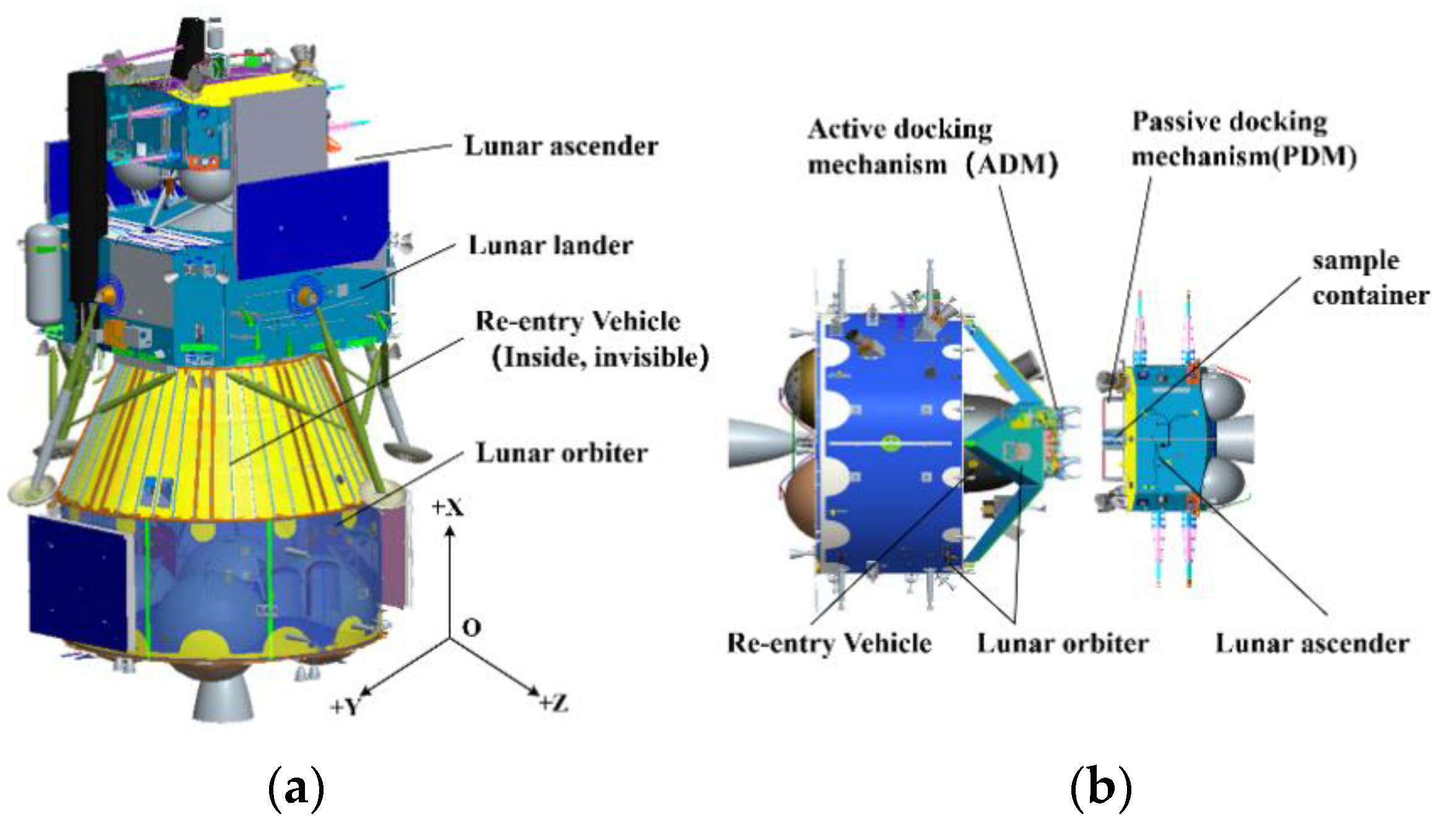
- Initial capture of the container: At the beginning, the transfer mechanism and the sample container are on two different crafts, the lunar orbiter and the lunar ascender. Before the start of the transfer, the transfer mechanism should be able to overcome a certain initial deviation and realize a reliable capture of the sample container.
- (b)
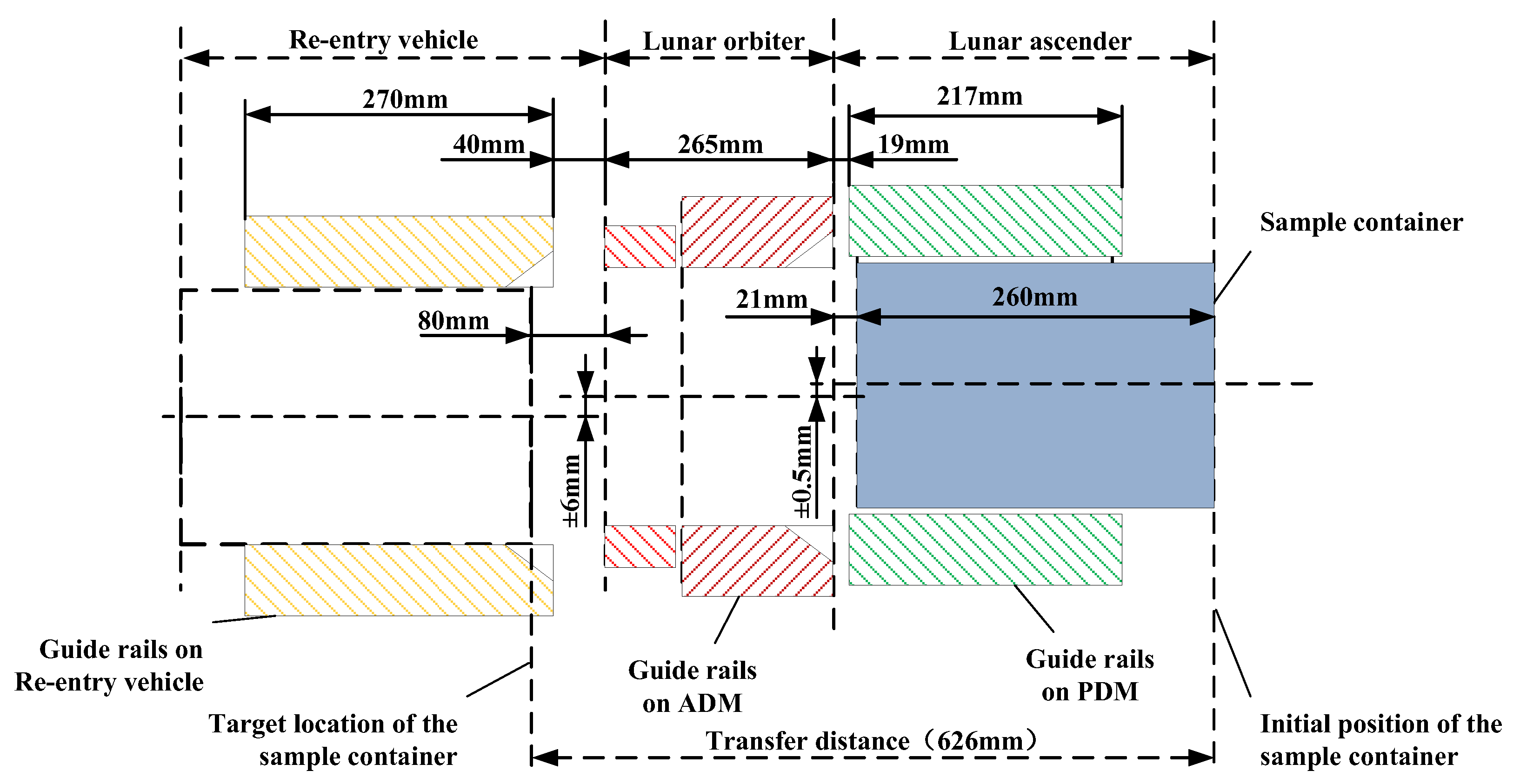
- Automatic and smooth transfer of the sample container: The controlled movement of the sample container is about 626 mm from the initial position in the lunar ascender to the target position in the re-entry vehicle. The transfer process should be adapted to possible positional deviations and frictional resistance and should maintain a smooth movement of the sample container to avoid additional impact loads that may cause structural damage to the container.
- (c)
- Automatic recovery: After the completion of the sample container transfer, the transfer mechanism should be capable of being reset and retracted in order to facilitate the hatch close of the re-entry vehicle.
2. General Design of the Transfer Mechanism
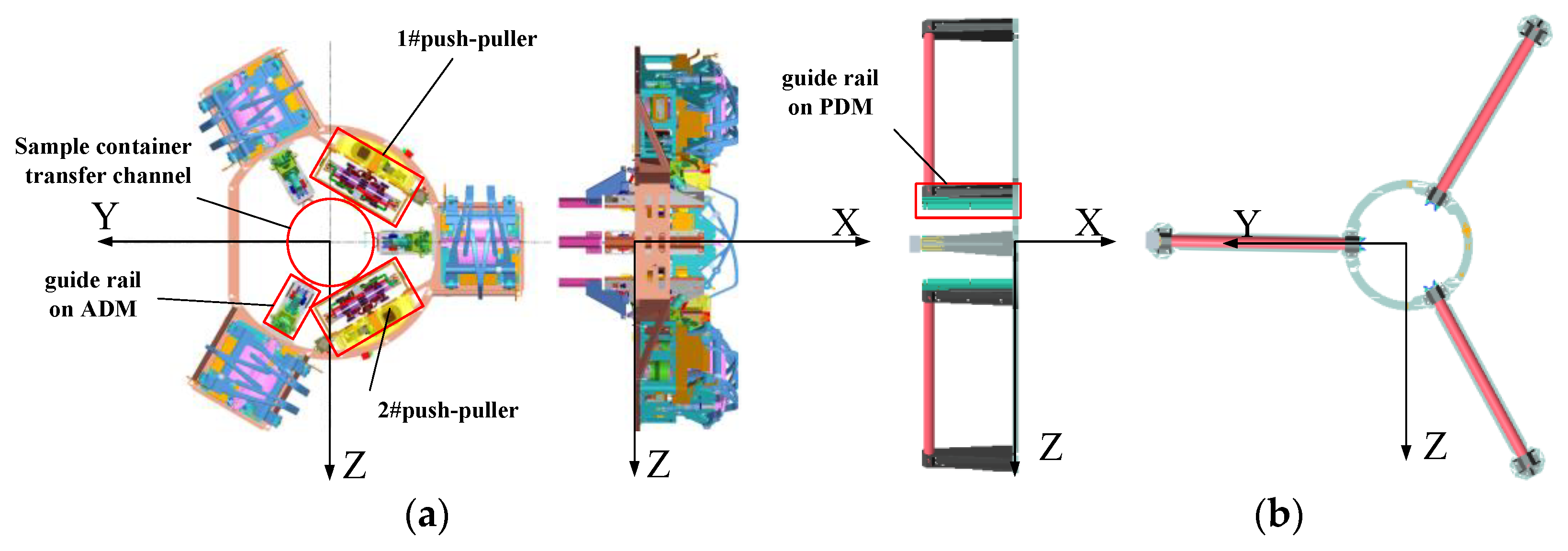
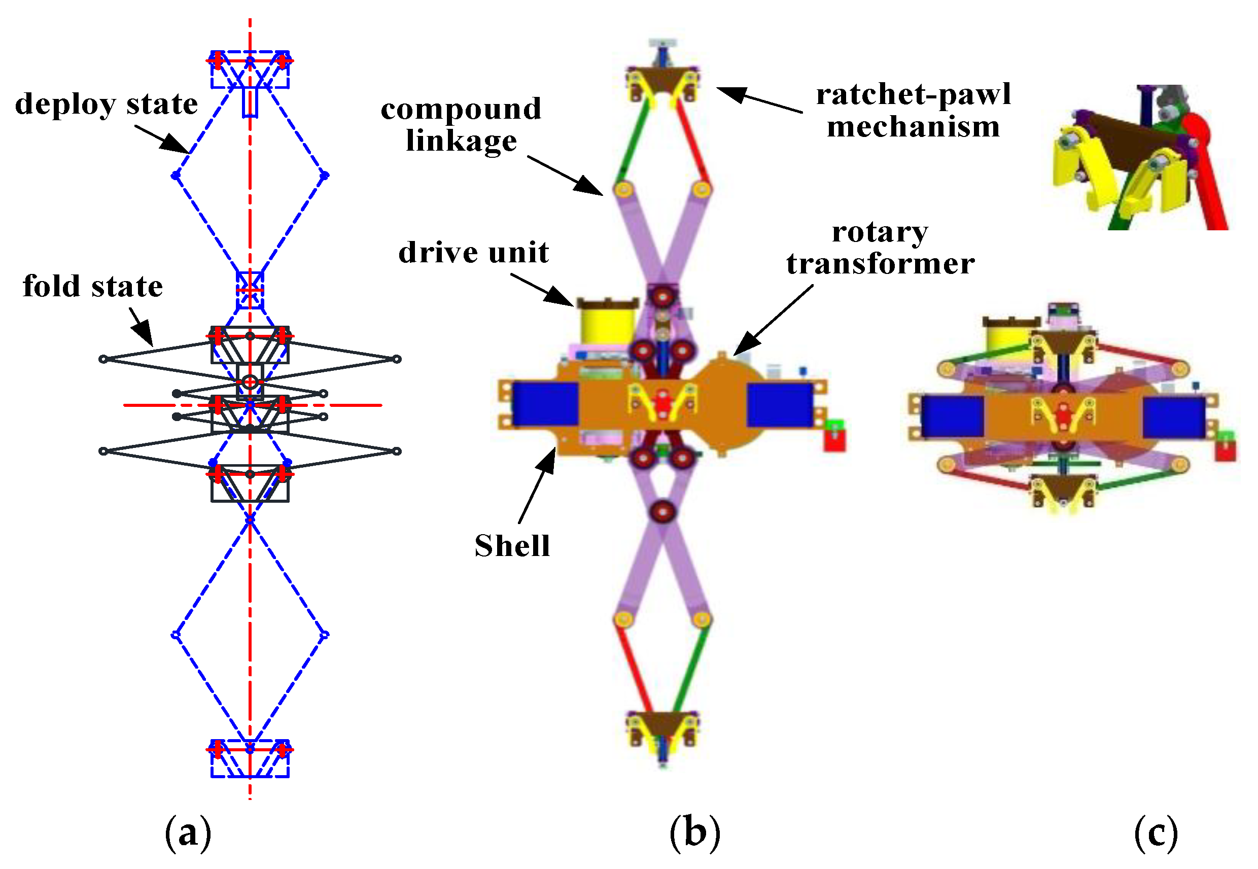
2.1. Composition and Configuration
2.2. Detailed Design of Transfer Mechanism
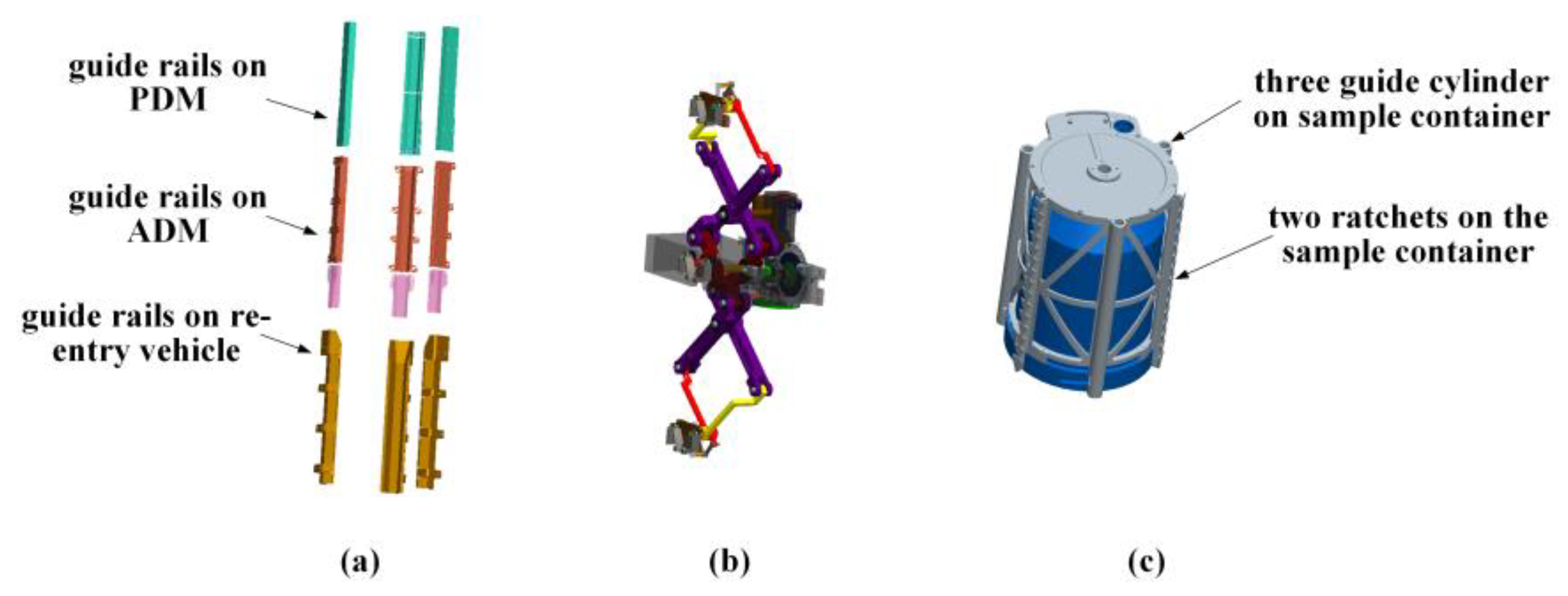
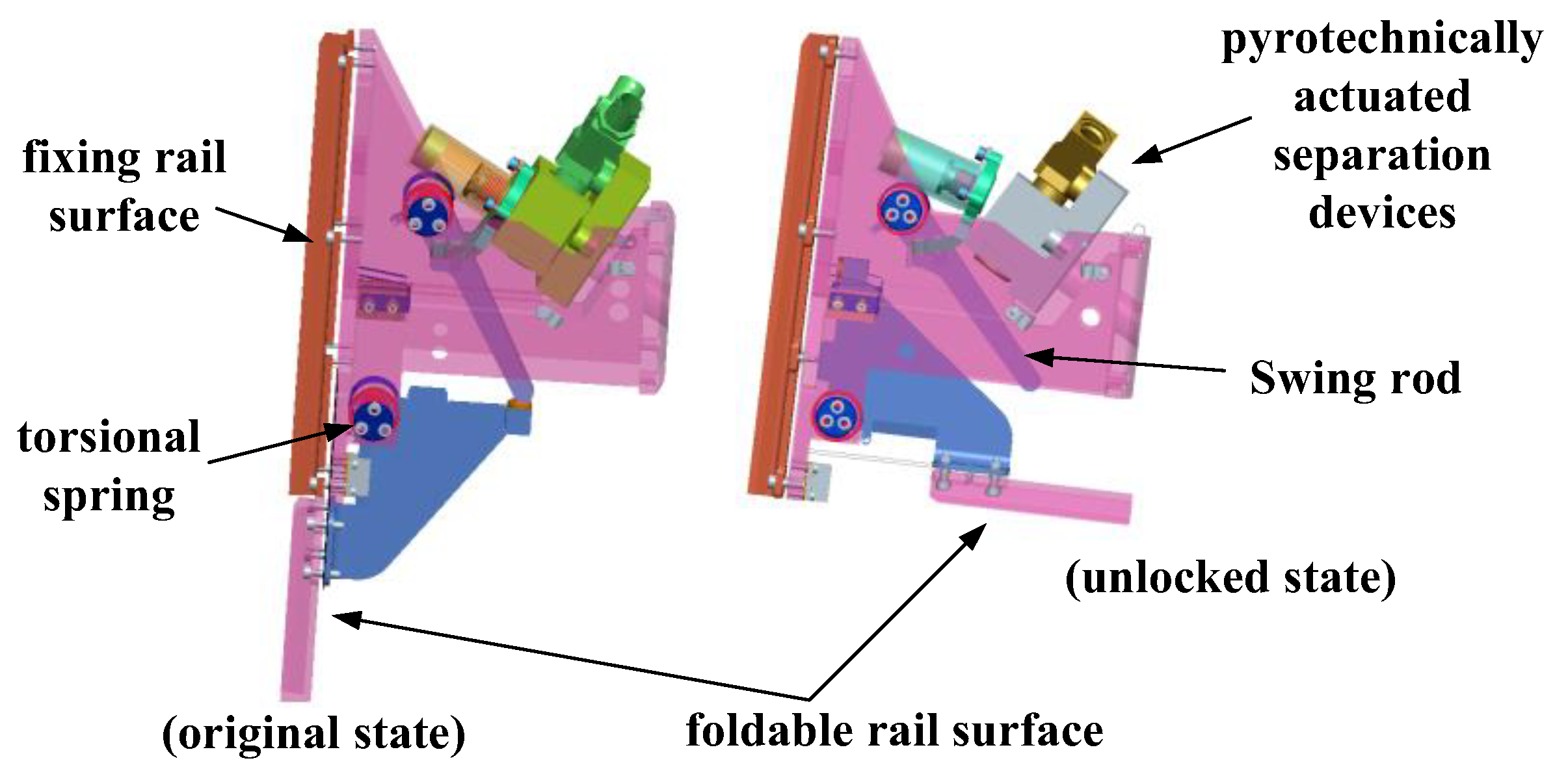
2.2.1. Guide Rails
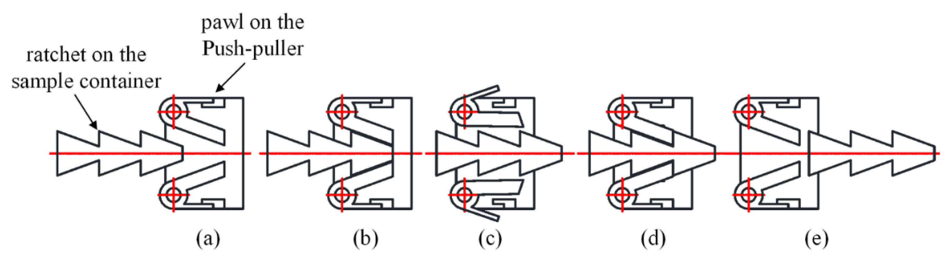
2.2.2. Push-Puller
- (a)
- Firstly the ratchet is kept still and the pawl is driven by the push-puller close to the ratchet (Figure 10a).
- (b)
- The pawl continues to move forward and contact with the ratchet, both of which are designed with a tolerant rake angle to accommodate the initial capture (Figure 10b).
- (c)
- The pawl continues to move forward. Under the influence of the push force, the pawl overcomes the torsional spring and passes through the ratchet on the rack in turn (Figure 10c).
- (d)
- After the pawl moves to the maximum position, it starts to move backward driven by the push-puller. Due to the unidirectional movement characteristics of the pawl and the ratchet, the ratchet and the pawl remain relatively stationary, driving the sample container backward until the push-puller is withdrawn in place (Figure 10d).
- (e)
- When the push-puller deploys again, the ratchet engages with other pawls and remains still, and the original pawl could be naturally disengaged from the ratchet of the sample container under the driving force of the push-puller so that the sample container is finally released (Figure 10e).
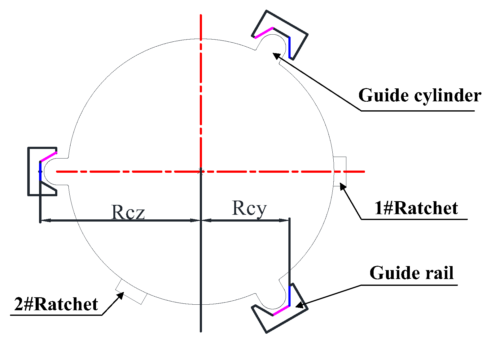
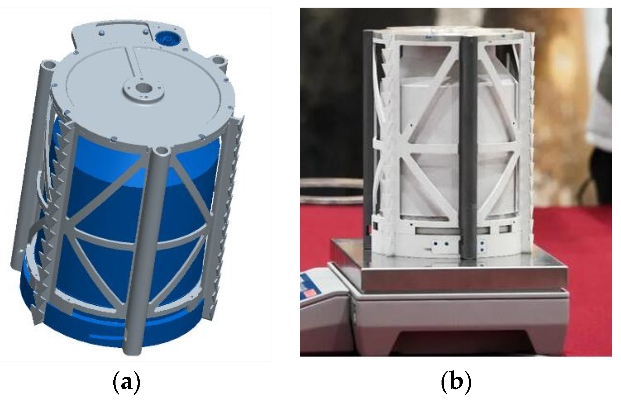
2.2.3. Attachment on the Sample Container
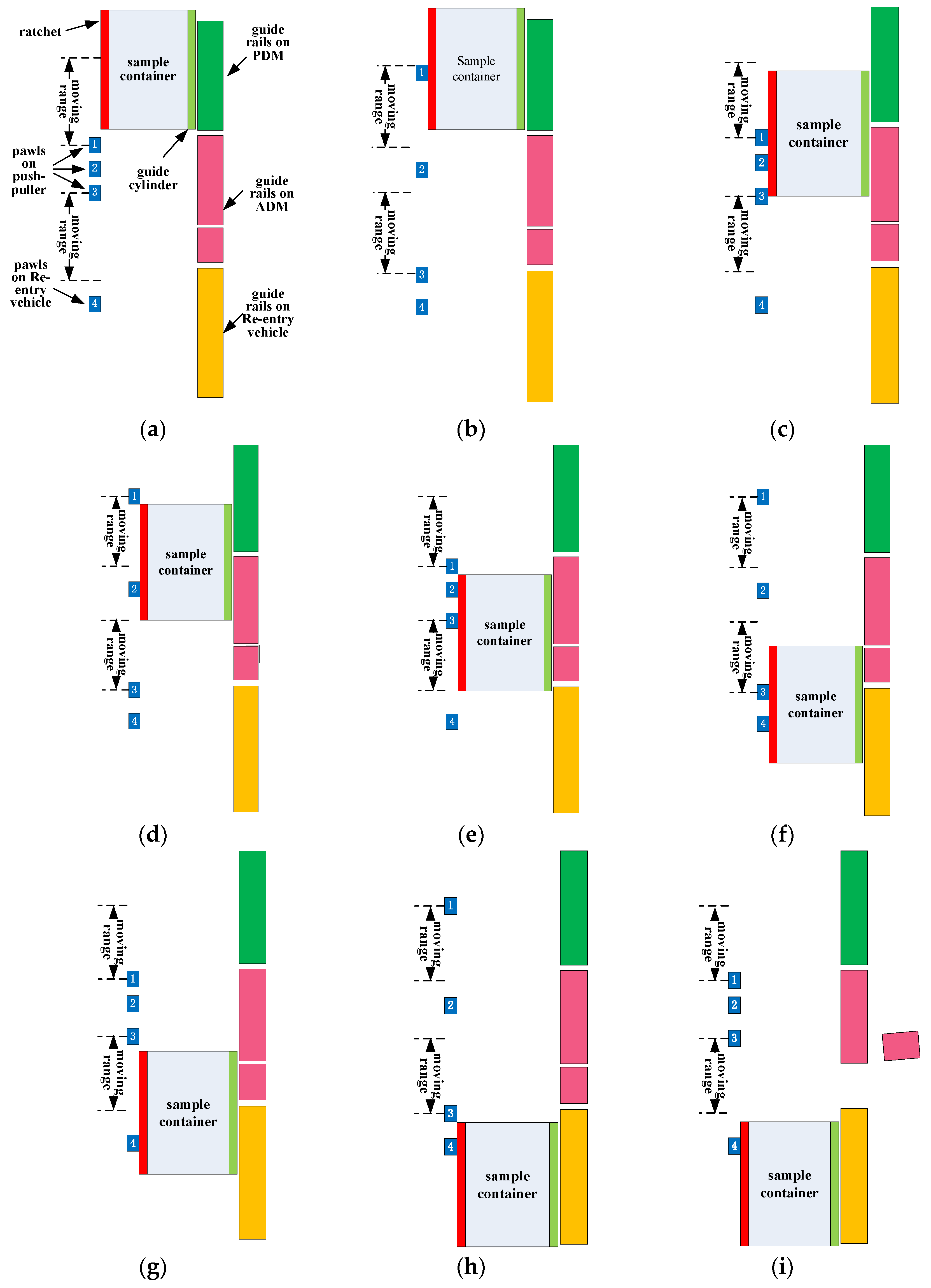
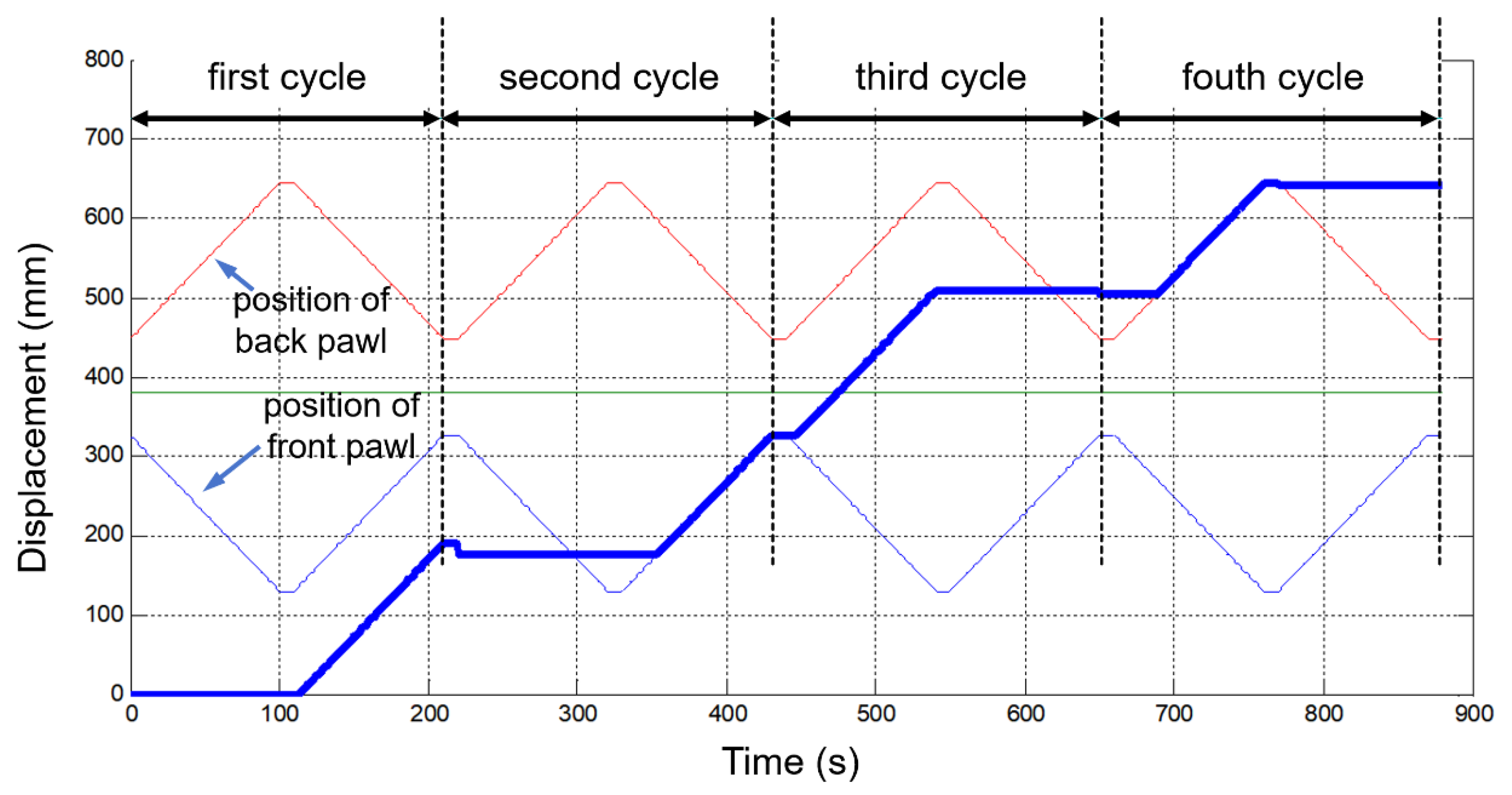
2.3. Working Process
- (a)
- Initial state of the sample container before transfer.
- (b)
- The push-puller deploys for the first time, and the #1 pawl captures the sample container.
- (c)
- The push-puller folds for the first time, the sample container moves forward about 190 mm driven by the #1 pawl, and the #2 pawl captures the container.
- (d)
- The push-puller deploys for the second time, the sample container remains still under the capture of the #2 pawl, and the #1 pawl releases the container.
- (e)
- The push-puller folds for the second time, the sample container moves forward to about 327 mm under the action of the #2 pawl, and the #3 pawl captures the container.
- (f)
- The push-puller deploys for the third time, and the sample container moves forward to 508 mm under the action of the 3#3 and enters the re-entry vehicle, while the lock (#4 pawl) in the re-entry vehicle captures the container.
- (g)
- The push-puller folds for the third time, the sample container remains still under the capture of the #4 pawl, and the #3 pawl releases the container.
- (h)
- The push-puller deploys for the fourth time, the sample container moves forward under the action of #4 pawl, and the container moves to the target position in the re-entry vehicle.
- (i)
- The push-puller folds for the fourth time and resets to the initial position, and the guide rails on ADM are retracted.
3. Resistance Analysis of the Transfer Process
- (a)
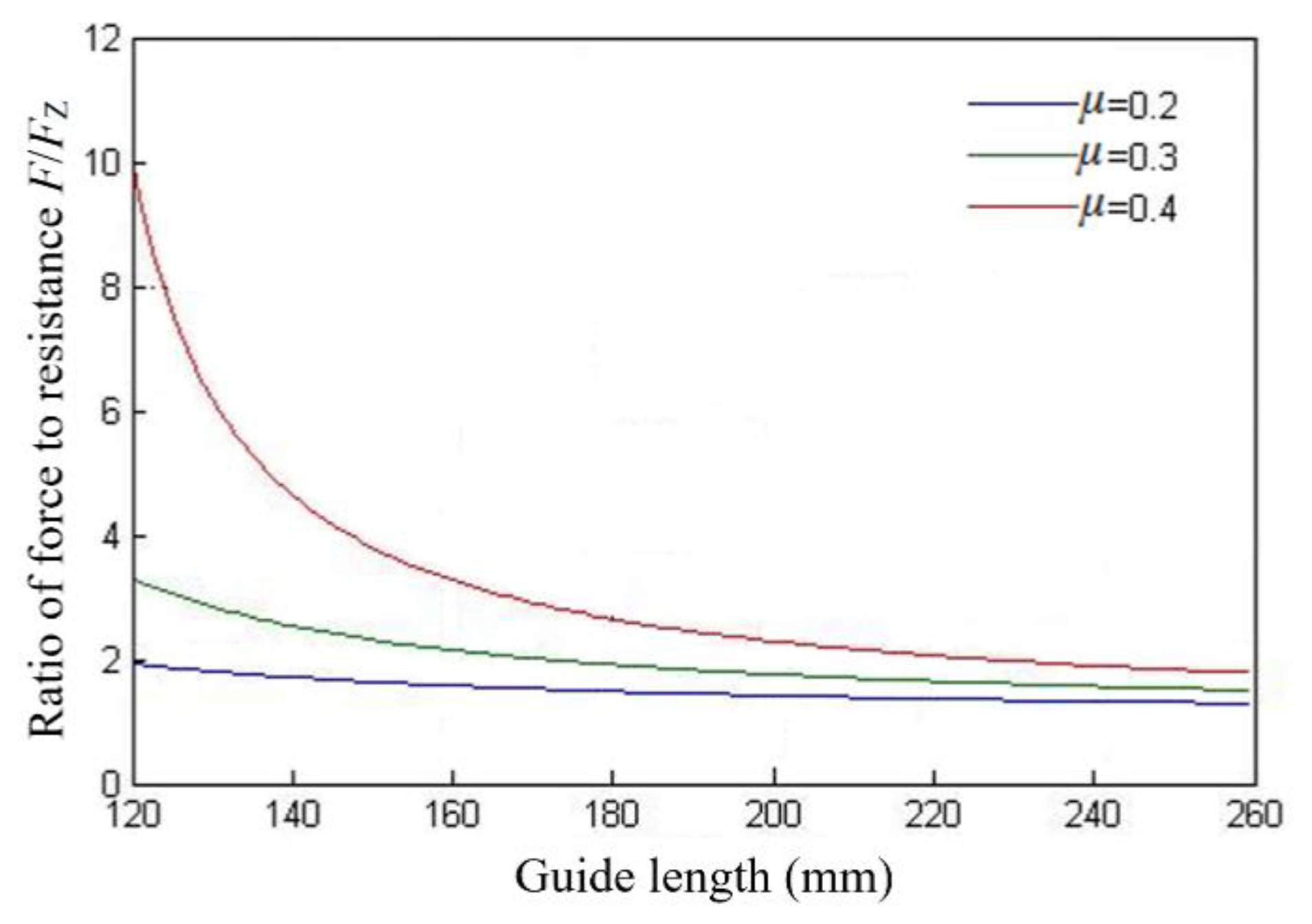
- The frictional resistance generated by the contact between the guide rails and the guiding surface of the sample container. It is related to the overturning moment on the container, the effective length of the guide rail, and the coefficient of friction of the guiding surface.
- (b)
- The resistance load of the container in contact with the one-way lock or locking mechanism of the sample compartment of the re-entry vehicle. The trigger force of a single set of locking mechanisms is designed to be less than 5 N.
- (c)
- The resistance load when the container passes through a non-operating pawl. The passing resistance of a single set of pawl mechanisms is designed to be less than 5 N.
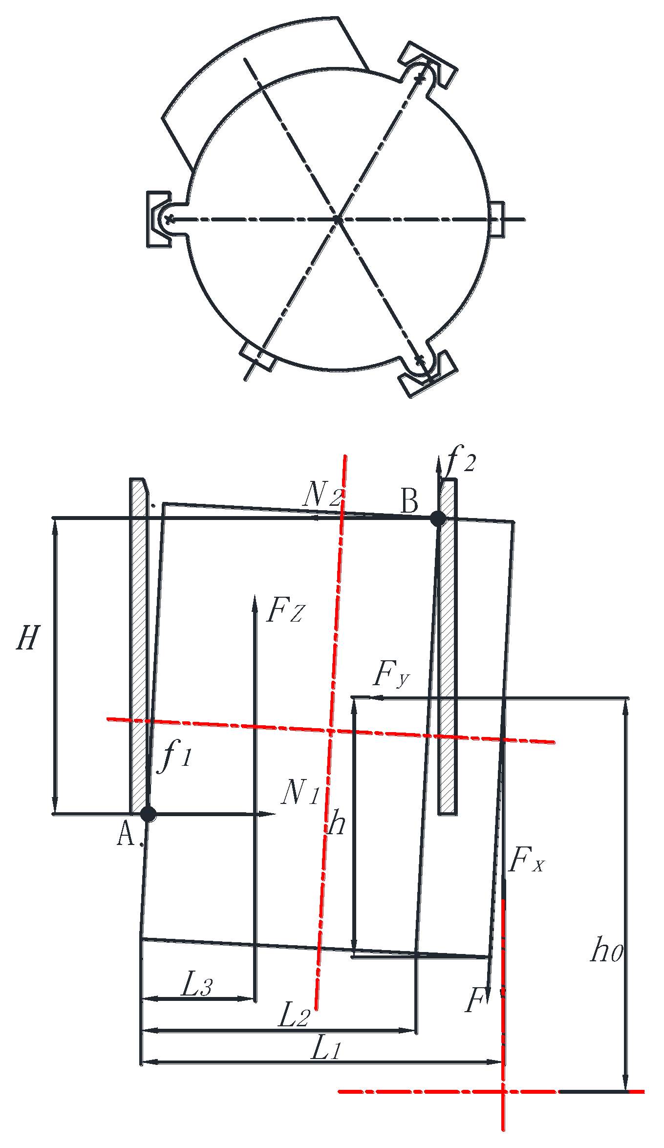
- (a)
- Force condition of the sample container in one single segment of the guide rail. In this state, the sample container moves in a single segment of guide rail, and it is deflected by the driving force of the transfer mechanism. The guide rails on PDM, ADM, or re-entry vehicle act with the guiding structure on the sample container to generate friction, and the driving force overcomes this friction force and the resistance force to push the sample container moving forward.
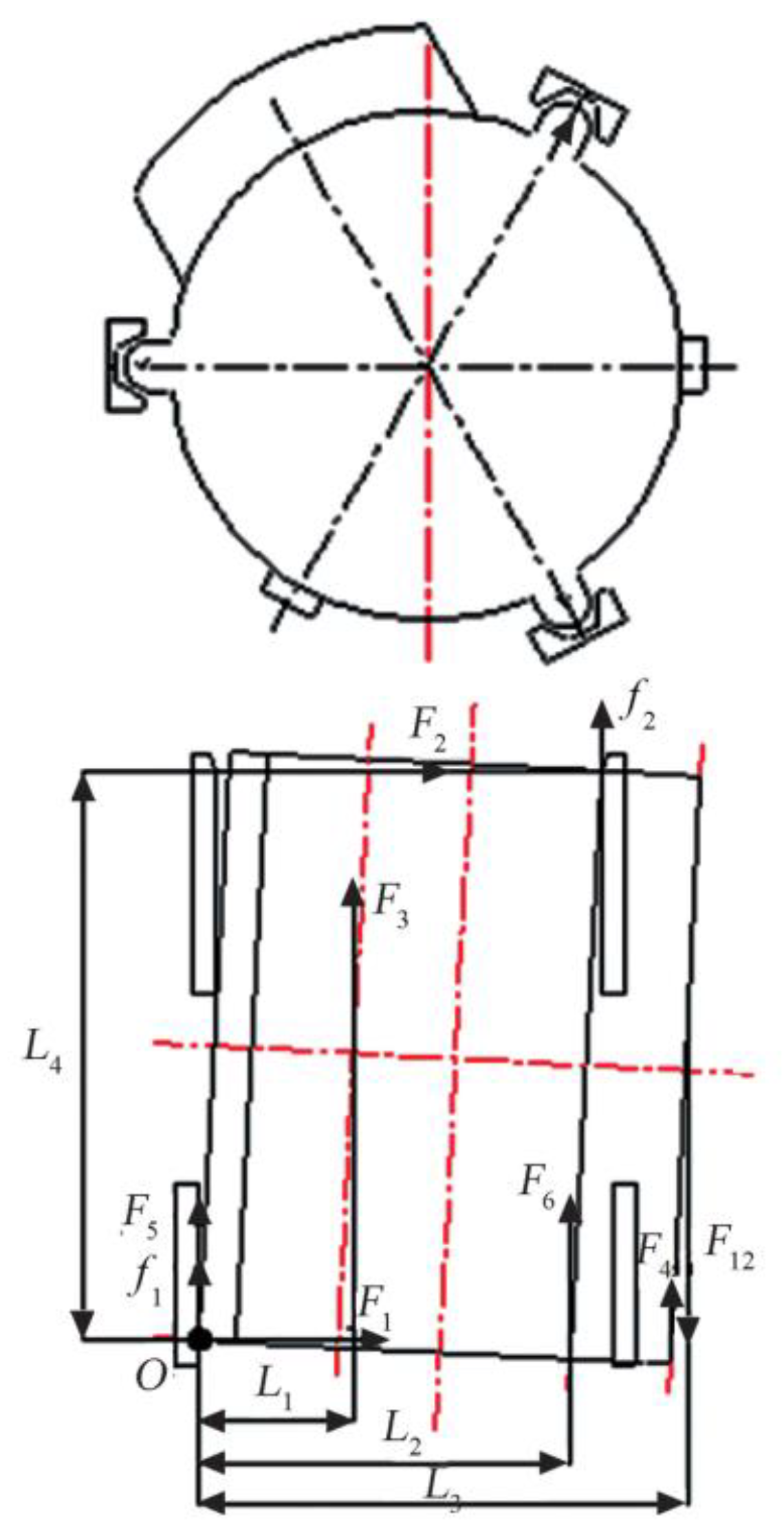
- (b)
- Force condition of the sample container as it enters the transition segment of the next guide rail. When the sample container enters the transition segment of the next guide rail, the back end of the guiding structure interacts with the previous guide rail to generate position pressure and friction, and the front end of the guiding structure interacts with the angled surface of the next guide rail to generate positive pressure and friction. The driving force overcomes the friction force and the resistance force to push the sample container moving forward.
3.1. Analysis of Resistance Sensitive Factors
3.2. Calculation of Resistance for the Whole Process
4. Validation
4.1. Experimental Validation
4.2. In-Orbit Flight Validation
5. Conclusions
Author Contributions
Funding
Data Availability Statement
Conflicts of Interest
References
- Mallapaty, S. China set to retrieve first Moon rocks in 40 years. Nature 2020, 587, 185–186. [Google Scholar] [CrossRef]
- Yang, M.; Zhang, G.; Zhang, W.; Peng, J.; Ruan, J.; Wang, Y.; Zhang, H.; Hong, X.; Zhang, Y.; Zha, X.; et al. Technical design and implementation of Chang’e-5 robotic sample return mission on lunar surface. Sci. Sin. Technol. 2021, 51, 738–752. (In Chinese) [Google Scholar] [CrossRef]
- Yang, W.; Lin, Y. New lunar samples returned by Chang’E-5: Opportunities for new discoveries and international collaboration. Innovation 2021, 2, 100070. [Google Scholar] [CrossRef]
- Siddiqi, A.A.; Launius, R. Deep Space Chronicle: A Chronology of Deep Space and Planetary Probes 1958–2000. Military Bookshop: Washington, DC, USA, 2002. [Google Scholar]
- Robinson, M.S.; Plescia, J.B.; Jolliff, B.L.; Lawrence, S.J. Soviet lunar sample return missions: Landing site identification and geologic context. Planet. Space Sci. 2012, 69, 76–88. [Google Scholar] [CrossRef]
- Scherer, L.R. The Apollo Missions. Highlights Astron. 2016, 2, 125–141. [Google Scholar] [CrossRef]
- Shaw, M.; Humbert, M.; Brooks, G.; Rhamdhani, A.; Duffy, A.; Pownceby, M. Mineral processing and metal extraction on the lunar surface-challenges and opportunities. Miner. Process. Extr. Metall. Rev. 2022, 43, 865–891. [Google Scholar] [CrossRef]
- Li, C.; Hu, H.; Yang, M.; Pei, Z.; Zhou, Q.; Ren, X.; Liu, B.; Liu, D.; Zeng, X.; Zhang, G. Characteristics of the lunar samples returned by the Chang’E-5 mission. Natl. Sci. Rev. 2022, 9, nwab188. [Google Scholar] [CrossRef] [PubMed]
- Carlson, R.W. Robotic sample return reveals lunar secrets. Nature 2021, 600, 39–40. [Google Scholar] [CrossRef]
- Ji, M.; Wang, C.; Sun, L. A structure used for the sealing and locking of lunar samples. In Proceedings of the 2018 International Conference on Service Robotics Technologies, Chengdu, China, 16–19 March 2018; pp. 38–41. [Google Scholar]
- Wang, W.; Zhang, C.; Qi, C.; Fu, L.; Wang, S. Stiffness design of active capture claw-type docking mechanism for lunar sample return. Aerospace 2023, 10, 794. [Google Scholar] [CrossRef]
- Qi, C.; Li, D.; Hu, Y.; Zheng, Y.; Wang, W.; Shou, X.; Gao, F. Learning-based distortion compensation for a hybrid simulator of space docking. IEEE Robot. Autom. Lett. 2023, 8, 3446–3453. [Google Scholar] [CrossRef]
- Cao, Y.; Fu, L.; Wang, W.; Liu, Z.; Liu, Z. End precision optimization method and its on-orbit application of sample transfer mechanism. Aerosp. Shanghai 2022, 39, 61–66. [Google Scholar]
- Stieberl, M.E. Robotic systems for the international space station. In Proceedings of the 1997 IEEE International Conference on Robotics and Automation, Albuquerque, NM, USA, 20–25 April 1997; pp. 3068–3073. [Google Scholar]
- Laryssa, P.; Lindsay, E.; Layi, O.; Marius, O.; Nara, K.; Aris, L.; Ed, T. International space station robotics: A comparative study of ERA, JEMRMS and MSS. In Proceedings of the 7th ESA Workshop on Advanced Space Technologies for Robotics and Automation, Noordwijk, The Netherlands, 19–21 November 2002; pp. 1–8. [Google Scholar]
- Oda, M.; Inaba, N. Results of NASDA’s ETS-VII robot mission and its applications. In Robotics Research; Hollerbach, J.M., Koditschek, D.E., Eds.; Springer: London, UK, 2000. [Google Scholar] [CrossRef]
- Moghaddam, B.M.; Chhabra, R. On the guidance, navigation and control of in-orbit space robotic missions: A survey and prospective vision. Acta Astronaut. 2021, 184, 70–100. [Google Scholar] [CrossRef]
- Xue, Z.; Liu, J.; Wu, C.; Tong, Y. Review of in-space assembly technologies. Chin. J. Aeronaut. 2021, 34, 21–47. [Google Scholar] [CrossRef]
- Qi, X.; Huang, H.; Miao, Z.; Li, B.; Deng, Z. Design and mobility analysis of large deployable mechanisms based on plane-symmetric Bricard linkage. J. Mech. Des. 2017, 139, 022302. [Google Scholar] [CrossRef]
- Gosselin, C.; Schreiber, L.-T. Redundancy in parallel mechanisms: A review. Appl. Mech. Rev. 2018, 70, 010802. [Google Scholar] [CrossRef]


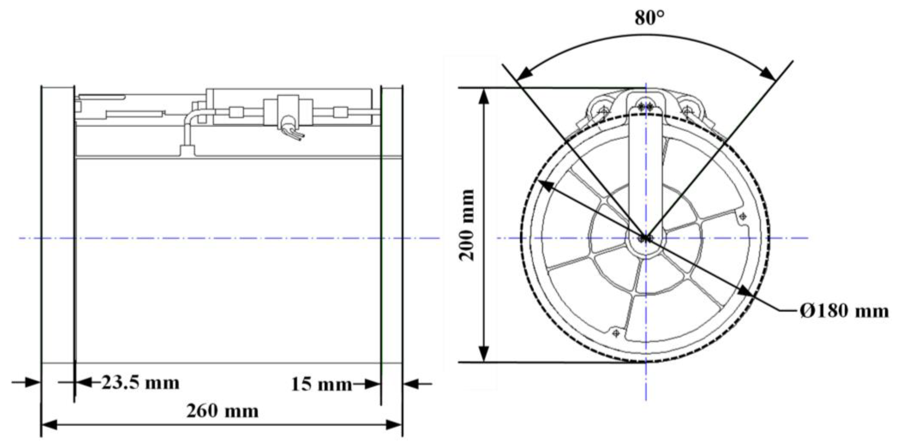
| No. | Item | Sample Container | Guide Rails on PDM | Guide Rails on ADM | Guide Rails on Re-Entry Vehicle | |
|---|---|---|---|---|---|---|
| Fixed Part | Retractable Part | |||||
| 1 | Length (mm) | 260.0 | 217.0 | 185.0 | 75.0 | 270.0 |
| 2 | Distance from center (mm) | 106.0 | 107.0 | 107.8 | 108.5 | 110.5 |
| 3 | Nominal gap to container (mm) | / | 1.0 | 1.8 | 2.5 | 4.5 |
| 4 | Angle of distribution (°) | 120 | ||||
| No. | Test Conditions | Maximum Current (A) | Maximum Transfer Resistance (N) | |
|---|---|---|---|---|
| 1 | Transfer mechanism 1#working | +Y 5 mm | 0.11 | 27.94 |
| 2 | −Y 5 mm | 0.12 | 30.48 | |
| 3 | +Z 5 mm | 0.12 | 30.48 | |
| 4 | −Z 5 mm | 0.15 | 38.10 | |
| 5 | Transfer mechanism 2#working | +Y 5 mm | 0.11 | 27.94 |
| 6 | −Y 5 mm | 0.10 | 25.40 | |
| 7 | +Z 5 mm | 0.11 | 27.94 | |
| 8 | −Z 5 mm | 0.16 | 40.64 | |
| 9 | Two transfer mechanism working | +Y 5 mm | 0.15 | 38.10 |
| 10 | −Y 5 mm | 0.08 | 20.32 | |
| 11 | +Z 5 mm | 0.10 | 25.40 | |
| 12 | −Z 5 mm | 0.10 | 25.40 | |
Disclaimer/Publisher’s Note: The statements, opinions and data contained in all publications are solely those of the individual author(s) and contributor(s) and not of MDPI and/or the editor(s). MDPI and/or the editor(s) disclaim responsibility for any injury to people or property resulting from any ideas, methods, instructions or products referred to in the content. |
© 2023 by the authors. Licensee MDPI, Basel, Switzerland. This article is an open access article distributed under the terms and conditions of the Creative Commons Attribution (CC BY) license (https://creativecommons.org/licenses/by/4.0/).
Share and Cite
Wang, W.; Cui, Y.; Qi, C.; Cao, Y.; Zhang, Y.; Zhang, C.; Wang, S. Design of In-Orbit Sample Container Transfer Mechanism for Chang’E-5 Lunar Sample Return Mission. Aerospace 2023, 10, 992. https://doi.org/10.3390/aerospace10120992
Wang W, Cui Y, Qi C, Cao Y, Zhang Y, Zhang C, Wang S. Design of In-Orbit Sample Container Transfer Mechanism for Chang’E-5 Lunar Sample Return Mission. Aerospace. 2023; 10(12):992. https://doi.org/10.3390/aerospace10120992
Chicago/Turabian StyleWang, Weijun, Yuxin Cui, Chenkun Qi, Yanyan Cao, Yuhua Zhang, Chongfeng Zhang, and Shigang Wang. 2023. "Design of In-Orbit Sample Container Transfer Mechanism for Chang’E-5 Lunar Sample Return Mission" Aerospace 10, no. 12: 992. https://doi.org/10.3390/aerospace10120992