Article

Effects of Injector Configuration on the Detonation Characteristics and Propulsion Performance of Rotating Detonation Engine (RDE)

Department of Aerospace Engineering, Pusan National University, Busan 46241, Republic of Korea
*
Authors to whom correspondence should be addressed.
Aerospace 2023, 10(11), 949; https://doi.org/10.3390/aerospace10110949
Submission received: 10 October 2023 / Revised: 2 November 2023 / Accepted: 6 November 2023 / Published: 8 November 2023

Abstract

:
Fuel injection and mixing affect the characteristics of detonation initiation and propagation, as well as the propulsion performance of rotating detonation engine (RDE). A study on the injector is carried out in the present investigation. A rectangular-shaped hole-type fuel injector (RHFI) and slit-type fuel injector (SFI) were designed and compared experimentally at equivalent conditions. The investigation of the detonation propagation modes and the analysis of propulsion performance were carried out using fast Fourier transform (FFT), short-time Fourier transform (STFT), and unwrapped image post-processing. Under 50, 75, and 100 g/s flow rate conditions at an equivalence ratio of 1.0 ± 0.05, the RHFI has relatively stable detonation propagation characteristics, higher thrust, and specific impulse performance. Additionally, the results of the experiment indicate that the number of detonation waves affects performance.

1. Introduction

A detonation is a shock wave sustained by the energy released by combustion [1]. The detonation offers the theoretical advantages of pressure gain combustion (PGC). The detonation propulsion system ideally has higher thermal efficiency rather than a Brayton cycle [2,3,4]. Therefore, based on this advantage, detonation propulsion research has been conducted over the past decades [5,6,7,8]. The PDE (pulsed detonation engine) and RDE (rotating detonation engine) have representatively been proposed as propulsion engines that use detonation. The PDE obtains thrust by generating a detonation wave using DDT (deflagration to detonation transition) in a tube closed at one end. However, it requires periodic operation to perform propellant charging, ignition, and purge sequence. On the other hand, once RDE generates the detonation wave, it propagates circumferentially at a speed of several thousand m/s. It has the advantage of having a simple operating process rather than PDE. Therefore, active research has been conducted on RDE over the past decade. In recent years, practical research and benefits have been reported [9,10,11,12]
Research is being conducted to implement PGC, which is realized via detonative combustion. Wu et al. [13] carried out thermodynamic cycle analyses and found that detonative combustion is not completely identical to the Humphrey cycle, but it generally has similar characteristics to the Humphrey cycle. Nordeen et al. [14] studied the thermodynamics of the RDE using numerical calculations. The resulting total entropy production is less than that produced by the Brayton cycle. Zhang et al. [15] conducted a numerical study and reported that detonation waves that rotate along the RDE channel led to pressure gain and, as a result, a 30% increase in pressure compared to injection pressure. To achieve substantial pressure gain, satisfying four idealized operational processes is required [16]: (1) the supply of pre-mixed propellants, (2) delivering propellants to the combustion chamber without pressure loss, (3) combustion via Chapman–Jouguet (CJ) detonation without deflagration, and (4) no back-pressure effects on the injector due to high-pressure detonation waves. Therefore, approaching or achieving these conditions is essential for substantial efficiency improvement.
Among the four primary design elements affecting RDE performance and characteristics, the injector influences fuel atomization, mixing, combustion efficiency, and the occurrence of deflagration. Thus, the injector plays a crucial role in reaching idealized processes. Liu et al. [17] conducted a numerical study and confirmed that PGC is achieved when the effective injection area ratio of premixed propellant injectors is 0.55 or higher. Goto et al. [18] performed experimental research using two different fuel injectors of varying sizes and observed differences in detonation velocity based on the injector diameter. Plaehn et al. [19] carried out experimental research on the influence of the injector location on the RDE length direction, and the results indicated that when it is located more than 5 mm away from the RDE head, a transition to deflagration occurred. Matsuoka et al. [20] conducted an experimental study with a geometric blockage ratio and suggested that the RDE operation is limited in the region of the lower geometric blockage ratio. Specific studies on RDE with respect to injector shapes were carried out by Bennewitz et al. [21], Rankin et al. [22], Duvall et al. [23], and Bohon et al. [24].
Research has been carried out on the complex influences of various design elements and experimental conditions on the detonation propagation mode. Zhao et al. [25] carried out numerical research on the propagation of multiple detonative waves. The combustor fueled by pre-mixed hydrogen/air mixtures is numerically investigated with detailed chemical mechanisms. The confirmation of new wave was obtained due to mutual reinforcement between traveling shock and deflagrative front. Wang et al. [26] also performed a numerical study to optimize the combustion and ignition mechanism via ozone addition. It was confirmed that increasing the ozone results in a switch from the single-wave mode to the multi-wave mode, providing a stable combustion interface. Bigler et al. [27] conducted experimental studies on chamber pressure and global performance changes related to mode transitions. It has been confirmed that under similar flow conditions, both dual-wave and triple-wave modes occur. When transitioning from the dual-wave to triple-wave mode, the detonation wave velocity decreases by 12%, chamber pressure decreases by 2.2%, and both thrust and specific impulse increase by 5.3%. Lin et al. [28] conducted experimental research on the RDE propagation mode. In the same experimental condition, it was observed that the dual-wave phase exhibits a lower detonation pressure peak compared to the single-wave phase. Additionally, in the counter-rotating mode, it was found to have a larger detonation velocity deficit compared to the single-wave mode. In addition, Jia et al. [29], Ding et al. [30], and Bluemner et al. [31] conducted a detonation propagation mode study.
Previous research [32] has concluded that the deficiency in the fuel-mixing performance of the slit-type fuel injector leads to detonation velocity deficits. Therefore, in this study, an experiment was conducted to improve fuel-mixing performance using different fuel injectors with aerospike nozzle as shown in Figure 1. The performance of RDE and the characteristics of detonation propagation were compared based on the respective fuel injector configurations.

2. Experiment Description

2.1. RDE Model

Figure 2 represents a schematic diagram of the RDE used in this study. The material of the RDE experimental model was SUS316, and gaseous ethylene (GC2H4) and gaseous oxygen (GO2) were used as the fuel and oxidizer, respectively. The combustion channel has a width of 4.5 mm and a length of 75 mm. The oxidizer was injected from a 0.5 mm slit injector towards the RDE exit direction, while fuel was radially injected into the combustion channel and the vertical direction relative to oxidizer injection for mixing. A conical aerospike of 30.0° was installed at the RDE exit for the optional expansion of burnt gas.
A pre-detonator (PDT) was used as the initiator of the RDE. It was designed with an inner diameter of 4.22 mm and a length of 110 mm. The PDT length was sufficient for DDT with a 4.22 mm inner diameter based on previous research results [33]. To generate a single detonation wave, the PDT was installed tangentially to the RDE combustion channel [34]. The PDT also used the same propellant as RDE and caused ignitions via a spark plug with a spark coil.
In this study, RDE experimental research was conducted with fuel injectors of different shapes. The reason for this is that previous research results [22] noted that slit-type fuel injector (SFI) have low mixing performance, leading to a low detonation velocity compared to CJ detonation velocity. Therefore, research was conducted on the fuel injector to improve fuel-mixing performance. The previous study used an SFI with a slit-type oxidizer injector. Figure 3 shows a schematic of the fuel injection structure used in the previous study and the current study. Gaseous oxygen supersonically flows into the combustion channel through a diverging nozzle. Gaseous ethylene e is injected into the combustion channel in the direction perpendicular to the oxygen flow. This propellant-mixing structure is very similar to a transverse jet in supersonic crossflow, exhibiting a scramjet fuel injection structure [35,36,37]. Focusing on this point, the fuel injector of the RDE was made by referring to the research results on scramjet fuel injection. Kim et al. [38] conducted an experimental study on the aspect ratio of the fuel injector relative to the scramjet. The result implies that a very long streamwise slit is desirable for combustion efficiency. Therefore, to improve propellant-mixing performances, devising a longer streamwise fuel injector than the SFI is needed.
Figure 4 depicts each injector’s three-dimensional fuel injection schematic. The rectangular-shaped hole-type fuel injector (RHFI) was designed to be longer than SFI by more than 3 times along the combustion channel direction. RHFI consists of 47 holes, with each being 1 mm2 in size. To obtain the same injection area of 47 mm2, the gap of SFI was set to 0.3 mm, and the gap was made using shim washers. The dimensions of the injectors are summarized in Table 1, and the injector used on the RDE is shown in Figure 5.

2.2. Experimental Apparatus

Figure 6 depicts the piping and instrumentation diagram (P&ID) of the gaseous propellant supply equipment used in this study. Propellant is provided by the 40 L cylinders, and downstream pressure is regulated via a dome regulator (Swagelok Inc., RDHN series). A flowmeter (Enbak Inc., FM153B, <0.2% FS accuracy) is installed after the dome regulator, and propellant feed and cutoff are controlled using pneumatic valves (TAVT Inc., TA05 series). A kHz pressure transmitter (WIKA Corp., S-20 series) was used for checking each gaseous supply line status and measuring the RDE plenum pressure. Propellant feed/cutoff control and status measurements were performed using a controller (National Instrument Inc., Austin, TX, USA, cRIO-9045) with C modules (National Instrument Inc., NI 9205, NI9212, etc.), and they were monitored using LabVIEW FPGA 19.0.1 (Laboratory Virtual Instrument Engineering Workbench Field Programmable Gate Array) software.
Figure 7 depicts a schematic of the RDE measurement configuration. An MHz pressure transducer (PCB Piezotronics Inc., Depew, NY, USA, 113B24) was located at 3 mm from the RDE combustion channel head and installed with a recessed structure on the RDE. Moreover, to provide protection from the thermal load, silicon grease was used (SYNCO Corp., Bohemia, NY, USA, Super Lube). A MHz pressure transducer was used with a signal conditioner (PCB Piezotronics Inc., 482C05) to adjust the current source. Due to the high sampling rate required for the MHz pressure transducer, data were acquired using an oscilloscope (Yokogawa Inc., DL850E). To measure the wall pressure of the RDE channel, a pressure scanner (Scanivalve Inc., Liberty Lake, WA, USA, DSA3217, 16 ports) was used, and the capillary tube average pressure technique was applied [39]. The first channel of the pressure scanner is located 3 mm from the RDE combustion channel head, and it scans up to 61 mm at 10 mm intervals. A high-speed camera (Phantom Inc., San Francisco, CA, USA, v2512) is located at the exit of the RDE for capturing the detonation wave. The camera was set to a resolution of 256 × 256 pixels and a frame rate of 200,000 frames per second (fps). All these instruments were synchronized with a controller using a 1 MHz TTL (transistor–transistor logic) signal.

2.3. Mass Flow Rate and Loadcell Calibration

Before the combustion experiments, the mass flow rates of each injector were measured. The theoretical mass flow rate was calculated using Equation (1). Here, Ainj is the total area of the injector; Pple is the plenum pressure of each gas; T is the temperature, and a room temperature of 298 K is used; γ is the specific heat ratio; R is the ideal gas constant. Experimental values were obtained using a mass flow meter. The Ci flow coefficient was calculated by dividing the experimental mass flow rate and the theoretical mass flow rate, and it is shown in Equation (2). The flow coefficient of each injector is presented in Figure 8. The results of both fuel injectors have similar flow coefficients.
m ˙ i , t h e o r y = A i n j p p l e T γ R 2 γ + 1 ( γ + 1 ) / ( γ 1 )
C i = m ˙ i , e x p m ˙ i , t h e o r y
Figure 9 is the loadcell calibration result. Loadcell (CAS Corp., Columbus, OH, USA, SBA-25L) calibration was carried out using weights before the combustion experiment. Calibration was performed based on the output voltage from the loadcell amplifier (CAS Corp. WTM-500) and the weight value. The results of loadcell calibration are as follows: Cload is 98.56 N/V + 1.55. In the combustion experiment, the operation frequency of the loadcell amplifier was 1600 Hz.

2.4. Experimental Sequence

Figure 10 represents the experimental sequence, Figure 10a depicts the signal of each component, and Figure 10b shows the pressure history. The details of the experiment are as follows: (1) I pneumatic valve for RDE propellant supply and the solenoid valve for PDT propellant supply were opened. Due to the rapid response time and short delay of the PDT solenoid valve, a rapid pressure increase was observed. Conversely, the pressure of the RDE plenum has a delayed increase of 0.1 s. This delay is due to the approximately 0.025 s response time of the pneumatic valve and the 0.075 s delay caused by the distance between the pneumatic valve and the RDE. (2) Once plenum pressure stabilizes, (3) PDT ignites 0.4 s after the commencement of the experiment, and plenum pressure increases due to combustion. The propellant is fed into the RDE from 0.4 s to 0.8 s. Even after 0.8 s, the pressure history in Figure 10b is maintained. This is due to the distance between the RDE propellant valves and the RDE. (4) Subsequently, for purging, the pneumatic valve of the nitrogen supply meter is opened, and nitrogen purging is performed after a delay of 0.3 s. Likewise, this delay is due to the distance between the purge gas valve and the RDE.

3. Results and Discussion

The experiments were conducted under three different flow conditions: total mass flow rate of approximately 50, 75, and 100 g/s at an equivalence ratio of 1.0 ± 0.05. Each condition and the results are summarized in Table 2. Both fuel injectors had an increase in thrust, specific impulse, and detonation velocity as the mass flow rate increased. Unlike RHFI, the detonation number, NDW, is changed from 75 g/s to 100 g/s. These results are the same as the findings from a previous research study carried out by Bykovskii et al. [40].
However, under specific experimental conditions, unstable behavior, including changes in the rotation direction of the detonation waves, was observed via short-time Fourier transform (STFT) and unwrapped images.

3.1. Thurst Performance

Figure 11 is the thrust history of cases 3 and 4. Traw in the plots denotes raw thrust data from the load cell amplifier. Tinterval is the average value of 50 data on either side of the time point. the ignition time of PDT is 0.4 s, and thrust increases rapidly, followed by a period of significant oscillations lasting approximately 0.2 s. Subsequently, thrust is relatively stabilized after 0.2 s from ignition, and the same is observed at 0.6 s. Therefore, the thrust mean, TAvg, is calculated using data between 0.6 s and 0.8 s.
In all experimental conditions shown in Table 2, as the mass flow rate increases, the thrust and specific impulse increase, and these results are the same as reported in other research [41,42]. The experiments were carried out at a higher mass flow rate with SFI, except for cases 1 and 2, which were carried out in approximately 50 g/s mass flow rate conditions. Comparing case 3 and case 4, the thrust of the latter case is higher than the former. The TAvg of case 4 is 108.88 N at a mass flow rate of 74.78 g/s, and case 4 is 98.67 at a relatively higher value of 77.04 g/s. The specific impulse in case 4 using RHFI is 119.05 s, which is higher than that of SFI at 98.67 s. This result shows that RHFI exhibits higher performances than SFI, and it can have the same consequences in other experiments. Also, thrust variation was computed via Traw data. For case 3, the one-sigma value was 3.90 N, whereas for case 4, it was 2.92 N. This result shows that RHFI has a smaller variation in thrust compared to SFI, indicating that RHFI is more stable than SFI at mass flow rate conditions.

3.2. Detonation Propagation Modes
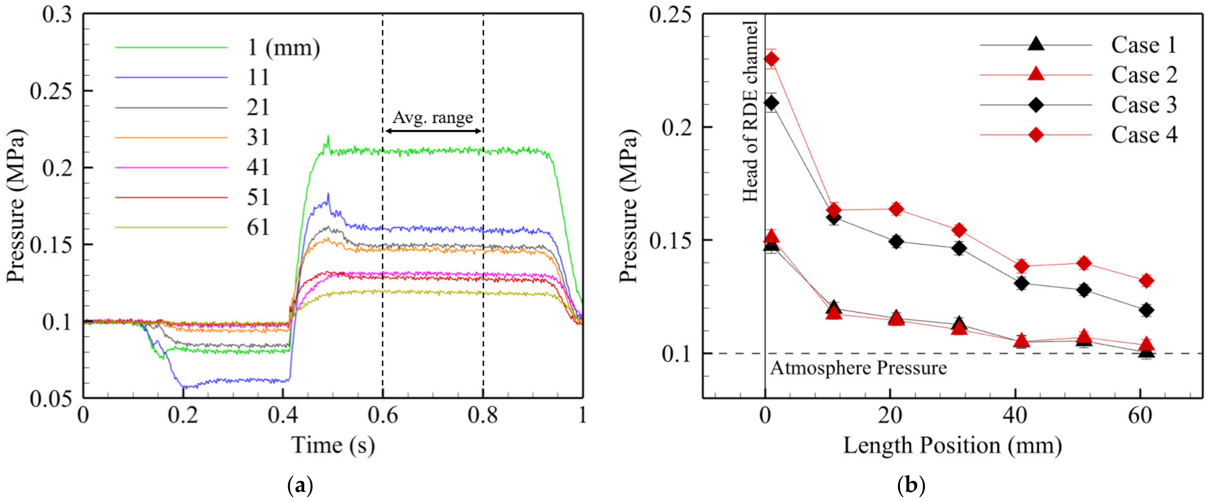
Figure 12a,b show the black-and-white inverted images of the exit of the RDE captured using the high-speed camera. IThe leftmost image was captured at 0.6 s and arranged at 5 μs intervals. In Figure 12a, two detonation waves propagate in a counterclockwise manner. Figure 12c represents the pressure history of the MHz pressure transducer for case 3, with two detonation waves rotating at approximately 56 μs intervals. In contrast to the results for case 3, Figure 12b displays three detonation waves propagating clockwise, with about 40 μs intervals between them. Comparing the graphs in Figure 12c,d, the former indicates higher pressure values. This is because more propellant can be burned per detonation wave in the dual-wave mode at the same mass flow rate. However, pressure peak variations in the pressure data are larger for case 3 compared to case 4, and the pressure profiles in each cycle appear to be less consistent. Consequently, this suggests relative instability, but further analyses over a wider time range are required.
Figure 13 depicts images from the high-speed camera aligned along the θ direction for the coordination of the leftmost image in Figure 12a [43]. A total of 300 images were stacked along the x-axis, allowing for the observation of the detonation propagation mode over 1.5 milliseconds. The black line is the path of detonation waves in the RDE. The rotating direction and number of waves can be identified clearly. Furthermore, Figure 13 provides consequences for detonation propagation characteristics at all experimental times based on post-processed data from the STFT and fast Fourier transform (FFT). Figure 13a reveals the counterclockwise propagation of two detonation waves over 1.5 ms, and the observed propagation mode exhibits a detonation propagation frequency of 17.903 kHz, which remains consistent from ignition to the end of the experiment, indicating no mode transitions. Figure 13b also shows the case without mode transitions. However, in contrast to Figure 13a, it indicates increased vibrations on the STFT plot. These results suggest that the detonation wave propagation in case 4 with RHFI is more stable when compared to case 3 with SFI. Additionally, these consequences can be further understood through the study of Sheng et al. [44]. In their study, they concluded the following. The vibration amplitude of the detonation wave height will decrease with the number of detonation waves, indicating that the stability of the RDE flow field will be improved as the detonation wave number increases. Therefore, the fuel injectors and different fuel injection structures cause differences in detonation propagation modes. Consequently, this affects the stability of detonation propagation characteristics.

3.3. Wall Pressure

Figure 14 presents wall pressure data measured with 500 samples per second and per channel (S/s/ch) over time. Between 0.1 and 0.4 s, negative pressure is formed due to the momentum of the oxidizer as the propellant is supplied. After ignition, the pressure rapidly increases, reaching its maximum at approximately 0.5 s. Subsequently, there is a stabilization period of about 0.2 s, excluding the first 1 mm. The pressure values from 0.6 s to 0.8 s for all four experimental cases were averaged and are shown in Figure 14b.

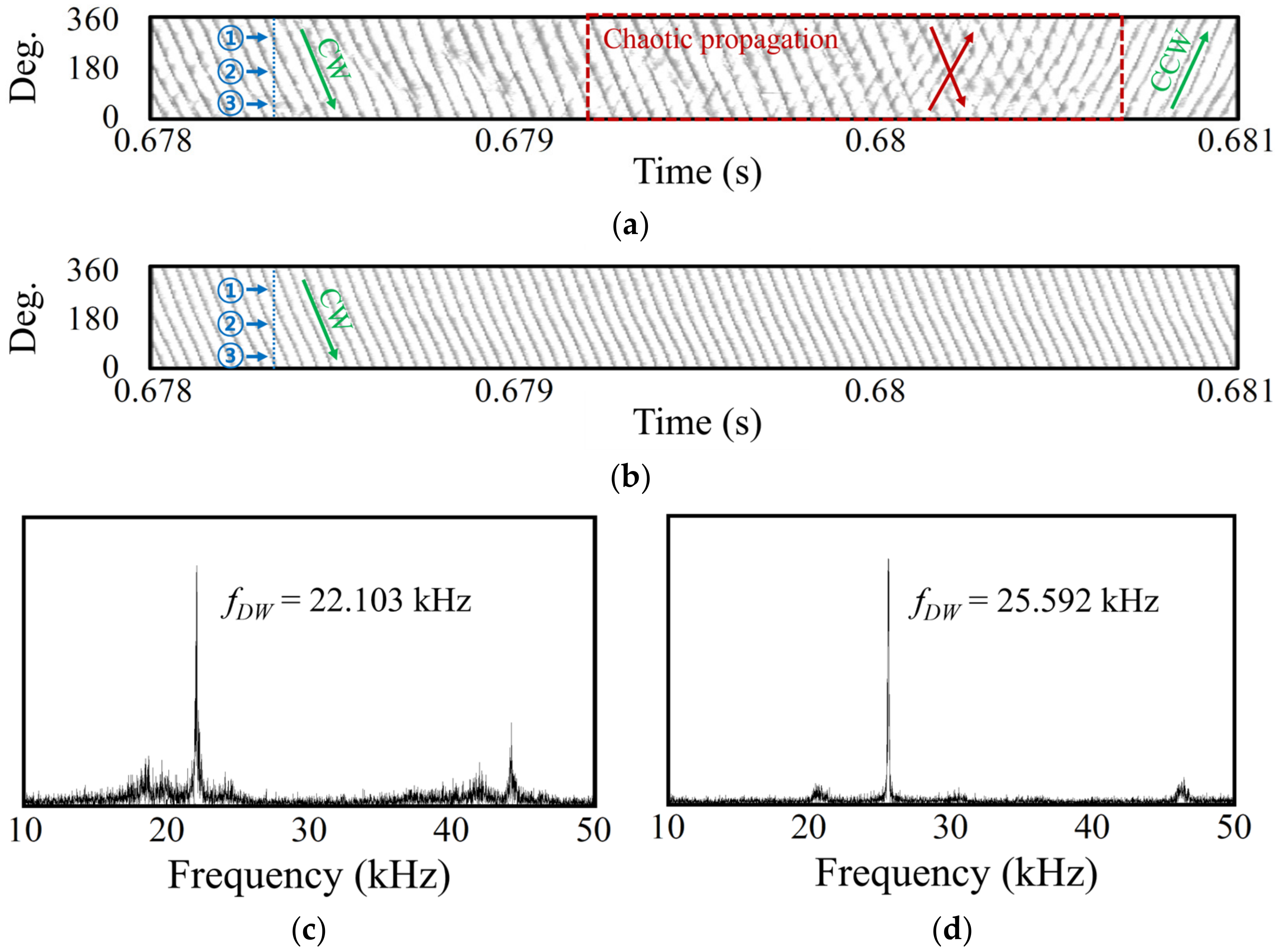
3.4. High Mass Flow Rate Condition
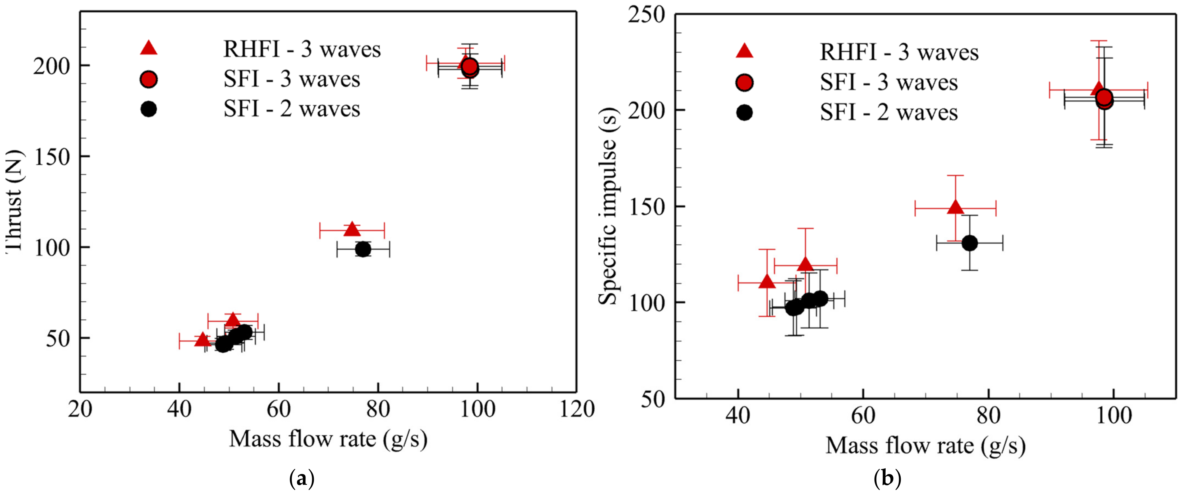
The RDE experimental model was partially ablated due to the high thermal load at the experimental condition of 100 g/s. Therefore, measurements were limited to thrust measurements and high-speed camera recording. Figure 15 presents processed images based on the rear-view photos of case 5 and case 6.
In Figure 15a, the three detonation waves propagation can be observed in both fuel injectors. At 0.678 s, the three detonation waves propagate clockwise. However, after 5 µs, at 0.6785 s, detonation waves propagating in the opposite direction are generated, and they develop further as time passes. Starting from 0.679 s, which is the same as the chaotic propagation region, there is a reversal in the rotating direction of the detonation waves with clockwise propagating waves. The reversal waves propagate aperiodically. However, as it is gradually reinforced, the origin waves disappear, and the waves only propagate counterclockwise direction. On the other hand, Figure 15b indicates waves that steadily propagate in the clockwise direction and relatively stable behavior with respect to the same experimental condition and detonation wave number.
Figure 15c,d show the results obtained after the FFT post-processing of 40,000 experimental photos taken over 0.2 s. Case 5 of SFI represents a relatively lower detonation propagation frequency than case 6 of RHFI. The detonation velocities are 1261 m/s and 1460 m/s for case 5 and case 6, respectively, indicating that, despite similar experimental conditions and the same number of detonation waves, case 6 has a 199 m/s faster detonation velocity. These results mean that more heat is generated at the same mass flow rate [45].

3.5. Performance

Figure 16 represents performance results according to the mass flow rate under an equivalence ratio of 1.00 ± 0.05. Figure 16a indicates the thrust performance based on different fuel injectors and the number of detonation waves. At the mass flow rate below 80 g/s, there is a mode difference between the SFI and the RHFI. Additionally, the thrust value of the RHFI is higher than the SFI. As the flow rate increases, thrust increases, and at high flow rates of about 100 g/s, both fuel injectors have the same mode conditions. Figure 16b also indicates a similar result, but it has a clearer difference compared to thrust, and the RHFI has a high specific impulse of more than 10% at less than 80 g/s. However, as the detonation mode changes, the specific impulse of SFI only exhibits a 3% difference. Although these results show that SFI still has lower performances compared to RHF, they suggest that the number of detonation waves affects performances.

4. Conclusions

To enhance fuel-mixing performance, an experimental study was conducted on the two kinds of fuel injectors in the RDE. Experiments were carried out under three different mass flow rate conditions at an equivalence ratio of 1.0 ± 0.05. The experimental results were analyzed based on MHz pressure transducer data and high-speed camera images, and the detonation propagation characteristics were analyzed using FFT, STFT, and unwrapped image post-processing:
(1)
High-speed camera images revealed differences in detonation modes between the two kinds of fuel injectors. Additionally, MHz pressure transducer data indicated that the SFI has larger variations with respect to pressure peak values, and STFT analysis demonstrated that the RHFI maintained a consistent detonation propagation frequency, while SFI had oscillations in detonation propagation frequencies during the combustion experiment. The fuel injectors and the result of the difference in the fuel injection structure caused differences in the detonation propagation mode. Consequently, this affected the stability of the detonation propagation characteristics.
(2)
In high mass flow rate experiments, the post-processing of images confirmed the propagation of three detonation waves for both types of injectors. However, the SFI exhibited chaotic behavior during the transition of propagation direction, and the detonation propagation frequency was relatively lower.
(3)
As a result of comparing thrust and specific impulse performance, it was confirmed that RHFI has higher performances and lower deviation than SFI. These consequences are caused by differences in the combustion efficiency of fuel injectors. As an additional result, performance improvements were observed when changing from the dual-wave mode to the triple-wave mode in SFI. These results suggest that the increase in the number of waves due to an increase in mass flow rate affected the performance. These results are consistent with [27,46].
With a long shape in the oxygen flow direction, injection fuel continuously comes into contact with oxygen, and a side vortex occurs, which further strengthens the series of mixing processes and enhances combustion reaction [38]. As a result, the RHFI has more stable detonation propagation characteristics and faster propagation velocity. Furthermore, these findings suggest that this had an impact on the performance of the RDE and that the RHFI can achieve higher performances compared to the SFI.

Author Contributions

Conceptualization, J.-Y.C.; Methodology, H.-S.H., M.-S.K., I.-H.K. and J.-Y.C.; Software, I.-H.K.; Validation, I.-H.K. and K.-H.L.; Formal Analysis, I.-H.K. and K.-H.L.; Investigation, I.-H.K. and M.-S.K.; Resources, I.-H.K. and K.-H.L.; Data Curation, I.-H.K. and M.-S.K.; Writing—original draft preparation, I.-H.K., K.-H.L., H.-S.H. and J.-Y.C.; Writing—review and editing, I.-H.K., K.-H.L., M.-S.K., H.K. and J.-Y.C.; Post-processing, I.-H.K.; Supervision, H.K. and J.-Y.C.; Project admin-istration, H.K. and J.-Y.C.; Funding acquisition, J.-Y.C. All authors have read and agreed to the published version of the manuscript.

Funding

This work was supported by the National Research Foundation of Korea (NRF) funded by the Republic of Korea government (MSIT) (NRF-2019R1A2C1004505 and 2022M1A3C2076724). The publication of this paper was supported by the BK21 FOUR of NRF funded by the Republic of Korea government (MOE).

Data Availability Statement

Data supporting the findings of this study are available from the corresponding author upon reasonable request.

Conflicts of Interest

The authors declare no conflict of interest.

References

  1. Turns, S.R. An Introduction to Combustion, Concepts and Applications, 3rd ed.; McGraw-Hill: New York, NY, USA, 2011. [Google Scholar]
  2. Wolański, P. Detonative propulsion. Proc. Combust. Inst. 2013, 34, 125–158. [Google Scholar] [CrossRef]
  3. Wintenberger, E.; Shepherd, J.E. Thermodynamic cycle analysis for propagating detonations. J. Propuls. Power 2006, 22, 694–698. [Google Scholar] [CrossRef]
  4. Bussing, T.; Pappas, G. Pulse detonation engine theory and concepts. In Developments in High-Speed-Vehicle Propulsion Systems; American Institute of Aeronautics and Astronautics, Inc.: Reston, VA, USA, 1996; pp. 421–472. [Google Scholar] [CrossRef]
  5. Bykovskii, F.A.; Mitrofanov, V.V. Detonation combustion of a gas mixture in a cylindrical chamber. Combust. Explos. Shock Waves 1980, 16, 570–578. [Google Scholar] [CrossRef]
  6. Kindracki, J.; Wolański, P.; Gut, Z. Experimental research on the rotating detonation in gaseous fuels–oxygen mixtures. Shock Waves 2011, 21, 75–84. [Google Scholar] [CrossRef]
  7. Anand, V.; Gutmark, E. Rotating detonation combustors and their similarities to rocket instabilities. Prog. Energy Combust. Sci. 2019, 73, 182–234. [Google Scholar] [CrossRef]
  8. Ma, J.Z.; Luan, M.Y.; Xia, Z.J.; Wang, J.P.; Zhang, S.J.; Yao, S.B.; Wang, B. Recent progress, development trends, and consideration of continuous detonation engines. AIAA J. 2020, 58, 4976–5035. [Google Scholar] [CrossRef]
  9. Goto, K.; Matsuoka, K.; Matsuyama, K.; Kawasaki, A.; Watanabe, H.; Itouyama, N.; Ishihara, K.; Buyakofu, V.; Noda, T.; Kasahara, J. Space flight demonstration of rotating detonation engine using sounding rocket S-520-31. J. Spacecr. Rocket. 2023, 60, 273–285. [Google Scholar] [CrossRef]
  10. Kawalec, M.; Wolański, P.; Perkowski, W.; Bilar, A. Development of a Liquid-Propellant Rocket Powered by a Rotating Detonation Engine. J. Propuls. Power 2023, 39, 554–561. [Google Scholar] [CrossRef]
  11. Teasley, T.W.; Fedotowsky, T.M.; Gradl, P.R.; Austin, B.L.; Heister, S.D. Current State of NASA Continuously Rotating Detonation Cycle Engine Development. In Proceedings of the AIAA SciTech 2023 Forum, San Diego, CA, USA, 12–16 June 2023. [Google Scholar] [CrossRef]
  12. Ishihara, K.; Yoneyama, K.; Watanabe, H.; Itouyama, N.; Kawasaki, A.; Matsuoka, K.; Kasahara, J.; Matsuo, A.; Funaki, I.; Higashino, K. Thrust Performance of Converging Rotating Detonation Engine Compared with Steady Rocket Engine. J. Propuls. Power 2023, 39, 297–307. [Google Scholar] [CrossRef]
  13. Wu, Y.; Ma, F.; Yang, V. System performance and thermodynamic cycle analysis of airbreathing pulse detonation engines. J. Propuls. Power 2003, 19, 556–567. [Google Scholar] [CrossRef]
  14. Nordeen, C.A. Thermodynamics of a rotating detonation engine. Combust. Explos. Shock Waves 2014, 50, 568–577. [Google Scholar] [CrossRef]
  15. Zhang, S.-j.; Ma, J.Z.; Wang, J. Theoretical and numerical investigation on total pressure gain in rotating detonation engine. AIAA J. 2020, 58, 4866–4877. [Google Scholar] [CrossRef]
  16. Raman, V.; Prakash, S.; Gamba, M. Nonidealities in Rotating Detonation Engines. Annu. Rev. Fluid Mech. 2022, 55, 639–674. [Google Scholar] [CrossRef]
  17. Liu, X.Y.; Luan, M.Y.; Chen, Y.L.; Wang, J.P. Flow-field analysis and pressure gain estimation of a rotating detonation engine with banded distribution of reactants. Int. J. Hydrog. Energy 2020, 45, 19976–19988. [Google Scholar] [CrossRef]
  18. Goto, K.; Yokoo, R.; Kawasaki, A.; Matsuoka, K.; Kasahara, J.; Matsuo, A.; Funaki, I.; Kawashima, H. Investigation into the effective injector area of a rotating detonation engine with impact of backflow. Shock Waves 2021, 31, 753–762. [Google Scholar] [CrossRef]
  19. Plaehn, E.W.; Walters, I.V.; Gejji, R.M.; Slabaugh, C.D. Bifurcation in Rotating Detonation Engine Operation with Continuously Variable Fuel Injection Location. J. Propuls. Power 2023, 39, 202–216. [Google Scholar] [CrossRef]
  20. Matsuoka, K.; Tanaka, M.; Noda, T.; Kawasaki, A.; Kasahara, J. Experimental investigation on a rotating detonation cycle with burned gas backflow. Combust. Flame 2021, 225, 13–19. [Google Scholar] [CrossRef]
  21. Bennewitz, J.W.; Bigler, B.R.; Pilgram, J.J.; Hargus, W.A., Jr. Modal transitions in rotating detonation rocket engines. Int. J. Energetic Mater. Chem. Propuls. 2019, 18, 91–109. [Google Scholar] [CrossRef]
  22. Rankin, B.A.; Richardson, D.R.; Caswell, A.W.; Naples, A.G.; Hoke, J.L.; Schauer, F.R. Chemiluminescence imaging of an optically accessible non-premixed rotating detonation engine. Combust. Flame 2017, 176, 12–22. [Google Scholar] [CrossRef]
  23. Duvall, J.; Chacon, F.; Harvey, C.; Gamba, M. Study of the effects of various injection geometries on the operation of a rotating detonation engine. In Proceedings of the 2018 AIAA Aerospace Sciences Meeting, Kissimmee, FL, USA, 8–12 January 2018; p. 0631. [Google Scholar]
  24. Bohon, M.D.; Bluemner, R.; Paschereit, C.O.; Gutmark, E.J. High-speed imaging of wave modes in an RDC. Exp. Therm. Fluid Sci. 2019, 102, 28–37. [Google Scholar] [CrossRef]
  25. Zhao, M.; Zhang, H. Origin and chaotic propagation of multiple rotating detonation waves in hydrogen/air mixtures. Fuel 2020, 275, 117986. [Google Scholar] [CrossRef]
  26. Wang, Y.; Tian, C.; Yang, P. Effects of Ozone Addition on Multi-Wave Modes of Hydrogen–Air Rotating Detonations. Aerospace 2023, 10, 443. [Google Scholar] [CrossRef]
  27. Bigler, B.R.; Burr, J.R.; Bennewitz, J.W.; Danczyk, S.; Hargus, W.A. Performance effects of mode transitions in a rotating detonation rocket engine. In Proceedings of the AIAA Propulsion and Energy 2020 Forum, Online, 24–28 August 2020. [Google Scholar] [CrossRef]
  28. Lin, W.; Zhou, J.; Liu, S.; Lin, Z.; Zhuang, F. Experimental study on propagation mode of H2/Air continuously rotating detonation wave. Int. J. Hydrog. Energy 2015, 40, 1980–1993. [Google Scholar] [CrossRef]
  29. Jia, B.; Zhang, Y.; Meng, H.; Meng, F.; Pan, H.; Hong, Y. Experimental Study on the Propagation Characteristics of Rotating Detonation Wave with Liquid Hydrocarbon/High-Enthalpy Air Mixture. Aerospace 2023, 10, 682. [Google Scholar] [CrossRef]
  30. Ding, C.; Wu, Y.; Xu, G.; Xia, Y.; Li, Q.; Weng, C. Effects of the oxygen mass fraction on the wave propagation modes in a kerosene-fueled rotating detonation combustor. Acta Astronaut. 2022, 195, 204–214. [Google Scholar] [CrossRef]
  31. Bluemner, R.; Bohon, M.; Paschereit, C.; Gutmark, E. Counter-rotating wave mode transition dynamics in an RDC. Int. J. Hydrog. Energy 2019, 44, 7628–7641. [Google Scholar] [CrossRef]
  32. Han, H.-S.; Lee, E.S.; Choi, J.-Y. Experimental Investigation of Detonation Propagation Modes and Thrust Performance in a Small Rotating Detonation Engine Using C2H4/O2 Propellant. Energies 2021, 14, 1381. [Google Scholar] [CrossRef]
  33. Han, H.-S.; Kim, J.-M.; Oh, S.; Choi, J.-Y. An Experimental Study on Characteristics of Small-scale PDE under Low-frequency Operating Conditions. J. Korean Soc. Propuls. Eng. 2018, 22, 81–89. [Google Scholar] [CrossRef]
  34. Shaw, I.J.; Kildare, J.A.; Evans, M.J.; Chinnici, A.; Sparks, C.A.; Rubaiyat, S.N.; Medwell, P.R. A theoretical review of rotating detonation engines. In Direct Numerical Simulations-An Introduction and Applications; IntechOpen: London, UK, 2019. [Google Scholar]
  35. Rothstein, A.; Wantuck, P. A study of the normal injection of hydrogen into a heated supersonicflow using planar laser-induced fluorescence. In Proceedings of the 28th Joint Propulsion Conference and Exhibit 1992, Nashville, TN, USA, 6–8 July 1992; p. 3423. [Google Scholar]
  36. Gruber, M.R.; Nejad, A.S.; Chen, T.H.; Dutton, J.C. Mixing and penetration studies of sonic jets in a Mach 2 freestream. J. Propuls. Power 1995, 11, 315–323. [Google Scholar] [CrossRef]
  37. Won, S.H.; Jeung, I.S.; Parent, B.; Choi, J.Y. Numerical investigation of transverse hydrogen jet into supersonic crossflow using detached-eddy simulation. AIAA J. 2010, 48, 1047–1058. [Google Scholar] [CrossRef]
  38. Kim, K.M.; Baek, S.W.; Kim, Y.G. Effects of Aspect Ratio of a Fuel Injection Nozzle into a Supersonic Air Stream on Combustion Characteristics. J. Korean Soc. Propuls. Eng. 2004, 8, 44–53. [Google Scholar]
  39. Paxson, D.E.; Hoke, J.L. Time averaged pressure measurement in fundamentally unsteady pressure gain combustion systems. NASA/TM—2013-217826. In Proceedings of the 45th Combustion/33rd Airbreathing Propulsion/33rd Exhaust Plume and Signatures/27th Propulsion Hazards Joint Subcommittee Meeting 2013, Monterey, CA, USA, 3–7 December 2012. No. E-20044Jan. 2013. [Google Scholar]
  40. Bykovskii, F.A.; Zhdan, S.A.; Vedernikov, E.F. Continuous spin detonations. J. Propuls. Power 2006, 22, 1204–1216. [Google Scholar] [CrossRef]
  41. Bennewitz, J.W.; Bigler, B.R.; Ross, M.C.; Danczyk, S.A.; Hargus, W.A., Jr.; Smith, R.D. Performance of a rotating detonation rocket engine with various convergent nozzles and chamber lengths. Energies 2021, 14, 2037. [Google Scholar] [CrossRef]
  42. Goto, K.; Nishimura, J.; Kawasaki, A.; Matsuoka, K.; Kasahara, J.; Matsuo, A.; Higashino, K. Propulsive performance and heating environment of rotating detonation engine with various nozzles. J. Propuls. Power 2019, 35, 213–223. [Google Scholar] [CrossRef]
  43. Bennewitz, J.; Bigler, B.; Schumaker, S.; Hargus, W. Automated image processing method to quantify rotating detonation wave behavior. Rev. Sci. Instrum. 2019, 90, 065106. [Google Scholar] [CrossRef] [PubMed]
  44. Sheng, Z.; Cheng, M.; Wang, J.P. Multi-wave effects on stability and performance in rotating detonation combustors. Phys. Fluids 2023, 35, 076119. [Google Scholar] [CrossRef]
  45. Lee, J.H.S. The Detonation Phenomenon; Cambridge University Press: Cambridge, UK, 2008. [Google Scholar]
  46. Yi, T.-H.; Lou, J.; Turangan, C.; Choi, J.-Y.; Wolanski, P. Propulsive performance of a continuously rotating detonation engine. J. Propuls. Power 2011, 27, 171–181. [Google Scholar] [CrossRef]
Figure 1. RDE experimental model and combustion test.
Aerospace 10 00949 g001
Figure 2. RDE experimental model schematics.
Aerospace 10 00949 g002
Figure 3. Two-dimensional schematic of fuel injection structure.
Aerospace 10 00949 g003
Figure 4. Three-dimensional fuel injection structure schematics: (a) flow schematics of the SFI and (b) flow schematics of the RHFI.
Aerospace 10 00949 g004
Figure 5. Injector of the RDE experimental model: (a) SFI, 0.3 mm in width; (b) RHFI consisting of 47 holes with a square shape of 1.0 mm2.
Aerospace 10 00949 g005
Figure 6. P&ID of the Pusan National University gas supply system.
Aerospace 10 00949 g006
Figure 7. Schematic of the RDE measurement configuration.
Aerospace 10 00949 g007
Figure 8. Results of the experimental mass flow rate based on ideal values.
Aerospace 10 00949 g008
Figure 9. Calibration results of a loadcell.
Aerospace 10 00949 g009
Figure 10. Experimental sequence of the RDE hot flow test: (a) time sequence of each valve and ignition; (b) pressure history along the sequence.
Aerospace 10 00949 g010
Figure 11. Thrust results of about 75.0 g/s test condition: (a) case 3, SFI; (b) case 4, RHFI.
Aerospace 10 00949 g011
Figure 12. Narrow range mode analysis, propagation direction, the number of detonation waves captured via high-speed camera snapshots, and the pressure history of the MHz pressure transducer: (a) two waves of case 3 with the slit-type fuel injector; (b) three waves of case 4 with the hole-type fuel injector; (c) pressure history of case 3 with the slit-type fuel injector; (d) pressure history of case 4 with the hole-type fuel injector.
Aerospace 10 00949 g012
Figure 13. Wide-range mode analysis, propagation direction, and the number of detonation waves shown in the unwrapped figure; STFT and FFT results: (a) case 3 with the slit-type fuel injector; (b) case 4 with the hole-type fuel injector.
Aerospace 10 00949 g013
Figure 14. Time-averaged wall pressure: (a) outer body wall pressure history of case 3; (b) time-averaged wall pressure along the RDE length direction.
Aerospace 10 00949 g014
Figure 15. High mass flow rate condition post-processing results, unwrapped figure, and FFT results based on snapshots: (a) chaotic propagation of case 5 with the slit-type fuel injector; (b) relatively stable propagation of case 6 with the hole-type fuel injector; (c) frequency domain of case 5 at 22.103 kHz; (d) frequency domain of case 6 at 25.592 kHz.
Aerospace 10 00949 g015
Figure 16. Performance results of RDE combustion experiments: (a) thrust performance; (b) specific impulse.
Aerospace 10 00949 g016
Table 1. Specs of each fuel injector type.
InjectorMaterialDepth (mm)Width (mm)NholesArea (mm2)
SlitSUS3160.3--47.1
HoleC10201.01.04747.0
Table 2. Experiment condition and results.
CaseInjector m ˙ (g/s) ΦT (N)ISP (s)NDWfDW (kHz)
1SFI48.821.0146.4697.01217.848
2RHFI50.801.0159.33119.05324.369
3SFI77.040.9898.67130.56217.903
4RHFI74.780.98108.88148.42324.555
5SFI98.571.00197.78204.54322.073
6RHFI97.621.03201.42210.33325.592
Disclaimer/Publisher’s Note: The statements, opinions and data contained in all publications are solely those of the individual author(s) and contributor(s) and not of MDPI and/or the editor(s). MDPI and/or the editor(s) disclaim responsibility for any injury to people or property resulting from any ideas, methods, instructions or products referred to in the content.

