1. Introduction
As a multifunctional flight platform, high-altitude long-endurance (HALE) UAVs under high-altitude and low-speed conditions have been used to carry out continuous surveillance of large areas or act as a communications relay. Pitch control of HALE UAVs is generally achieved via aerodynamic control surfaces (elevator). Research institutions or enterprises such as NASA [
1], DARPA [
2], Facebook [
3] in the United States, and Airbus [
4] in Europe have carried out research projects on HALE UAVs. Although the pitch channel is self-stabilizing, the effectiveness of the control surface is significantly dependent on the dynamic pressure and decreases rapidly with altitude. At an altitude of 20 km, the density and pressure decrease to 7.2% and 6.7% of their sea-level values, respectively [
5]. The articulated aerodynamic control surfaces not only disrupt the delicate aerodynamic shape of the wings but also generate increased drag and loss of lift due to the deflection of the control surfaces. Thus, some novel control methods are needed. The battery density of solar UAVs is large, the mass is relatively concentrated, and the mass usually accounts for 30~40% of the entire aircraft mass [
6]; therefore, the selection of the battery as the movable slider can obtain enough control moment. As a feasible alternative to traditional control systems, moving mass control (MMC) technology can meet these needs.
Moving mass control is an active control method for aircraft to achieve attitude control by changing the aircraft’s center of mass through the active movement of the internal mass and changing the relative position of the center of mass and external forces (such as the aerodynamics and propeller thrust) [
7]. Nelson [
8] first proposed an MMC method for aircraft in 1967 and proved its feasibility on re-entry vehicles. In the 1970s and 1990s, the research on MMC was mainly conducted in the United States and Russia and has realized engineering applications in missiles and satellites [
9]. After entering the 21st century, there continues to be research on the applications of MMC to underwater vehicles and satellites. In addition, in the research on unmanned aerial vehicles and stratospheric airships, a more stable and efficient control technology was urgently needed, and scholars once again turned their attention to MMC technology. In 2005, Yuan Changsheng proposed for the first time in his doctoral dissertation the idea of reducing the vertical (
Z-axis) position of the gravity center to improve the stability of microaircraft, and he proved in subsequent studies that longitudinal torque balance and static stability can be achieved without a horizontal tail [
10,
11]. In 2006, Gao Changsheng proposed to control the longitudinal motion of an airship by changing the axial position of its gravity center [
12]. In 2010, a series of studies on the application of MMC to UAVs and stratospheric airships emerged. Typical of these was a series of studies conducted by Erturk from 2013 to 2017 that established a complete dynamic model and proved that the application effect of MMC and its combination with aerodynamic control on small fixed-wing UAVs is better than that of traditional aerodynamic control [
13,
14,
15,
16]. Wang Kefan et al. [
17] proposed a control scheme for the lateral heading of small solar UAVs in near space using batteries as mass sliders and sliding rails arranged along the span direction. Chen Baihui et al. [
18] proposed a new dual-slider control strategy for small fixed-wing aircraft with MMC in the rolling channel. The prototype aircraft verified the effectiveness and engineering realizability of the scheme. In 2020, with the demand for HALE UAVs with a high aspect ratio, Wang Xiaoming first applied the concept of MMC to the roll control of HALE UAVs, which proved its feasibility and could limit the deformation of flexible wings with a high aspect ratio and optimize aeroelastic characteristics [
19]. It can be seen that after the concept of MMC was created in 1967, its application scenario has been continuously expanded along with the development of aircraft. It has been extended from spacecrafts to underwater aircrafts [
20], airships, small UAVs, and now high-aspect-ratio solar UAVs.
Establishing an accurate mathematical model is one of the key problems in MMC technology. This paper attempts to fill the research gap in MMC technology in the pitch control of high-aspect-ratio UAVs, especially that of HALE UAVs. It can be seen that considering the characteristics of HALE UAVs such as a high flight altitude, a low flight speed, and strict weight restrictions, the application of MMC in the pitch control of HALE UAVs has great potential.
In total, a UAV has six degrees of freedom (DOFs), and in this implementation, MMC controls only one of them: the pitch angle. Firstly, a longitudinal six-DOF mathematical model of a UAV based on an MMC scheme is established, including the aerodynamic force, propulsion, and moving-mass actuation. Secondly, based on the dynamic model, the impact of the slider on the motion of the UAV is qualitatively analyzed. Thirdly, the transfer functions are linearized by using the small-disturbance method. Then, the handling characteristics are analyzed, and the control efficiency is compared with that of a traditional elevator control scheme. Finally, the simulation results demonstrate the feasibility of the MMC scheme in the longitudinal control of a HALE UAV under high-altitude and low-speed conditions as well as its superiority over the traditional elevator control.
The remainder of this paper is laid out as follows.
Section 2 presents the nonlinear and linearized six-DOF mathematical models.
Section 3 analyzes the handing characteristics. The results and trim analysis are presented in
Section 4. The conclusions are discussed in
Section 5.
2. Materials and Methods
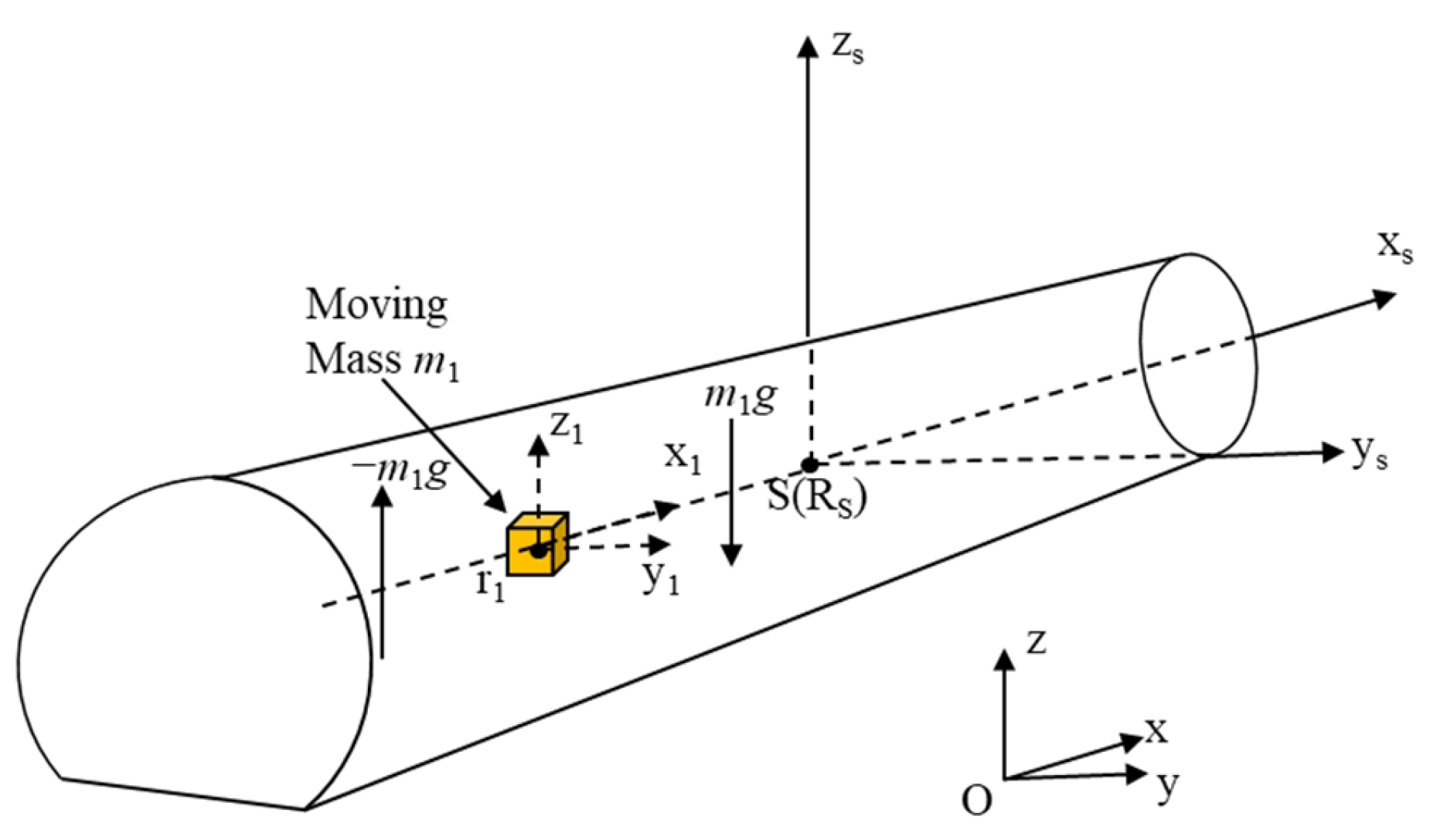
The basic configuration of the high-altitude, low-speed, high-aspect-ratio unmanned aerial vehicle studied in this paper is shown in
Figure 1 and
Figure 2, with the slider arranged longitudinally along the body.
The slider offset could generate the pitching moment to replace the elevator surface.
,
, and
are used to denote the mass of UAV body, slider, and the entire system, respectively; these satisfy the following relationship:
Thus, the ratios of body mass and slider mass to the mass of the entire system can be expressed as:
The position of the slider in the body coordinate system can be expressed as:
The slider is installed in the
oxBzB plane of the body coordinate system, and the slider is parallel to the
oxB axis, i.e.:
2.1. UAV System Description Based on MMC Scheme
UAV Configuration Based on MMC Scheme
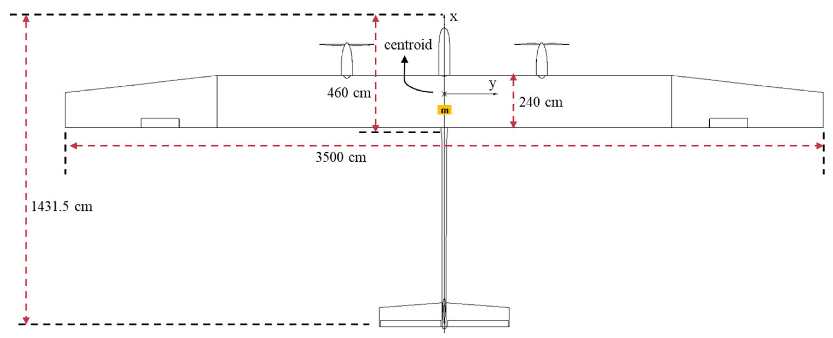
The basic configuration of the HALE UAV studied in this paper is shown in
Figure 2.
Based on the traditional configuration, a single sliding block was arranged longitudinally along the fuselage. The forward and backward movement of the slider could generate the pitching moment that enabled the UAV to carry out the pitching motion, thus realizing the replacement of the elevator plane. The lateral movement of the UAV was still controlled by the aileron and rudder.
In this scheme, the zero-bias position of the slider was located at the intersection point between the plane of oxBzB and the slide rail in the body frame. Compared with the conventional elevator control scheme, this had the advantage of being simple in structure and highly efficient in operation.
The position coordinates of the center of mass of the entire system, the center of mass of the body, and the center of mass of the slider in the body frame are
,
, and
, respectively. Therefore, one can write:
where
,
, and
are the position vectors of system centroid, body centroid, and slider centroid in body frame, respectively. Then:
To simplify the study, the following assumptions were made:
a. Ignore the effect of wind.
b. The density of the slider was large enough to be approximated as a particle.
c. The slide rail was fixed to the UAV body and was regarded as a part of the body.
d. The slide rail was located in the axis in the plane of the body frame, i.e., .
2.2. Motion Model Based on MMC Scheme
Based on Newton’s law of motion and moment of momentum theorem, the kinematic and dynamical models of the HALE UAV based on the MMC scheme are developed in this section, respectively. Among these, the translational kinematics equations of the center of mass are established in the geographic coordinate system The rotational kinematics equations, the translational dynamics equations, and the translational dynamics equations of the center of mass are established in the body frame.
2.2.1. Kinematic Model
The UAV kinematic equations based on the MMC scheme are identical to those based on the conventional elevator control scheme:
where
pn,
pe, and
ph are the position coordinates of the UAV in the ground coordinate system.
2.2.2. Dynamic Model
According to Newton’s law of motion and the theorem of moment of momentum, the kinematics model and dynamic model of the object studied in this paper were derived. The equation of dynamics can be obtained as:
in Equation (12) are the components of the combined force acting on the drone on the three axes of the body coordinate system and can be derived as:
And
in Equation (12) is given as:
Equations (14) and (15) are derived in
Appendix A.
in Equation (13) represents the triaxial components of the external torque received by the UAV in the body frame, and the inertia matrix can be expressed as:
According to the calculation rules of the inertia moment and inertia product, the following equations can be obtained:
where
,
,
,
,
, and
represent the inertia moments and inertia products of the body without the slider. For the surface configuration of the UAV studied in this paper,
=
= 0.
The derivative of Equation (17) is:
in Equation (13) is expressed as:
2.2.3. Force and Moment
In this section, the external force and torque of a HALE UAV based on a moving mass control scheme is modeled. Different from the traditional elevator control scheme, the mechanism of the MMC scheme to generate the pitching moment is to offset the system’s mass center through the slider’s movement to generate the gravity moment relative to the origin of the body frame.
The gravity
of the UAV system could be converted to the body coordinate system and is represented as:
The gravity acting point of the system is located at the center of mass S of the system, and the gravitational torque generated by it relative to the origin of the body frame can be expressed as:
To sum up, all the external forces and torques acting on the unmanned aerial vehicle system in the body frame are shown in Equations (22) and (23):
The three parts on the right in Equations (22) and (23) represent the force and moment of gravity, thrust, and aerodynamics, respectively.
2.2.4. Supplementary Equations
In order to solve the UAV equations based on the MMC scheme, it was necessary to supplement the equations regarding the angle of attack
, the angle of sideslip
, and the system centroid velocity
in the body frame:
2.3. Dynamic Model Analysis
Using Equations (12), (13), (22) and (23), the derivative of the velocity and angular velocity could be written as:
where
,
and
are written as:
As can be seen in the above dynamic model, for the HALE UAV based on an MMC scheme, the influence of the longitudinal single slider on the UAV’s dynamics is mainly reflected in the following aspects:
a. For centroid translational dynamics, since the term contains the position along the longitudinal movement of the slider, the sliding of the slider will affect the centroid translational dynamics of the UAV by changing the value of . The item also contains the slider moving speed in and acceleration , which means that the slider’s own motion state can also affect the centroid translational dynamics by changing the value of .
b. For rotational dynamics, the inertia tensor matrix contains the position where the slider moves along the longitudinal direction, so the sliding of the slider will change the moment of inertia and inertia product of the system, thus affecting the rotational dynamics of the UAV.
c. The term of gravity torque also contains , so the sliding of the slider will change the magnitude of the gravity torque generated by the system gravity vector on the body frame, thus affecting the attitude of the UAV.
d. contains the system’s moment of inertia and product of inertia as well as their derivatives, so the position of the slider and moving speed affect the value of and the UAV’s rotational dynamics.
e. The movement of the slider does not affect the system gravity , engine thrust , aerodynamic force , thrust moment , or aerodynamic moment .
2.4. Linearized Model of the UAV Longitudinal Motion
In order to quantitatively analyze the longitudinal dynamic characteristics of the HALE UAV based on the MMC scheme and conduct a modal analysis through numerical simulation, the linearized model of the UAV longitudinal motion was obtained by using the small disturbance linearization method:
where the state vector is expressed as
.
and
shown in Equations (31) and (32) are the state matrix and control matrix, respectively. In addition, the control vector
contains the position of the slider and the speed of the propeller motor.
where the specific expression of each parameter is as follows:
Since these five parameters include the system’s moment of inertia
, the moving position of the slider
, the static derivative of pitching moment with respect to the moving position of the slider
, and the static derivative of resistance with respect to the moving position of the slider
, the position of the slider moving along the longitudinal direction will affect the state matrix and control matrix by changing these parameters. These parameters embody the key characteristics of the MMC; that is, the slider affects the flight state of the aircraft by changing the center of gravity and moment of inertia of the aircraft. Therefore, the linear model of UAV longitudinal motion is different from that controlled by the traditional elevator plane. The remaining parameters in Equation (33) are shown in [
21].
3. Pitch Handling Characteristic Analysis
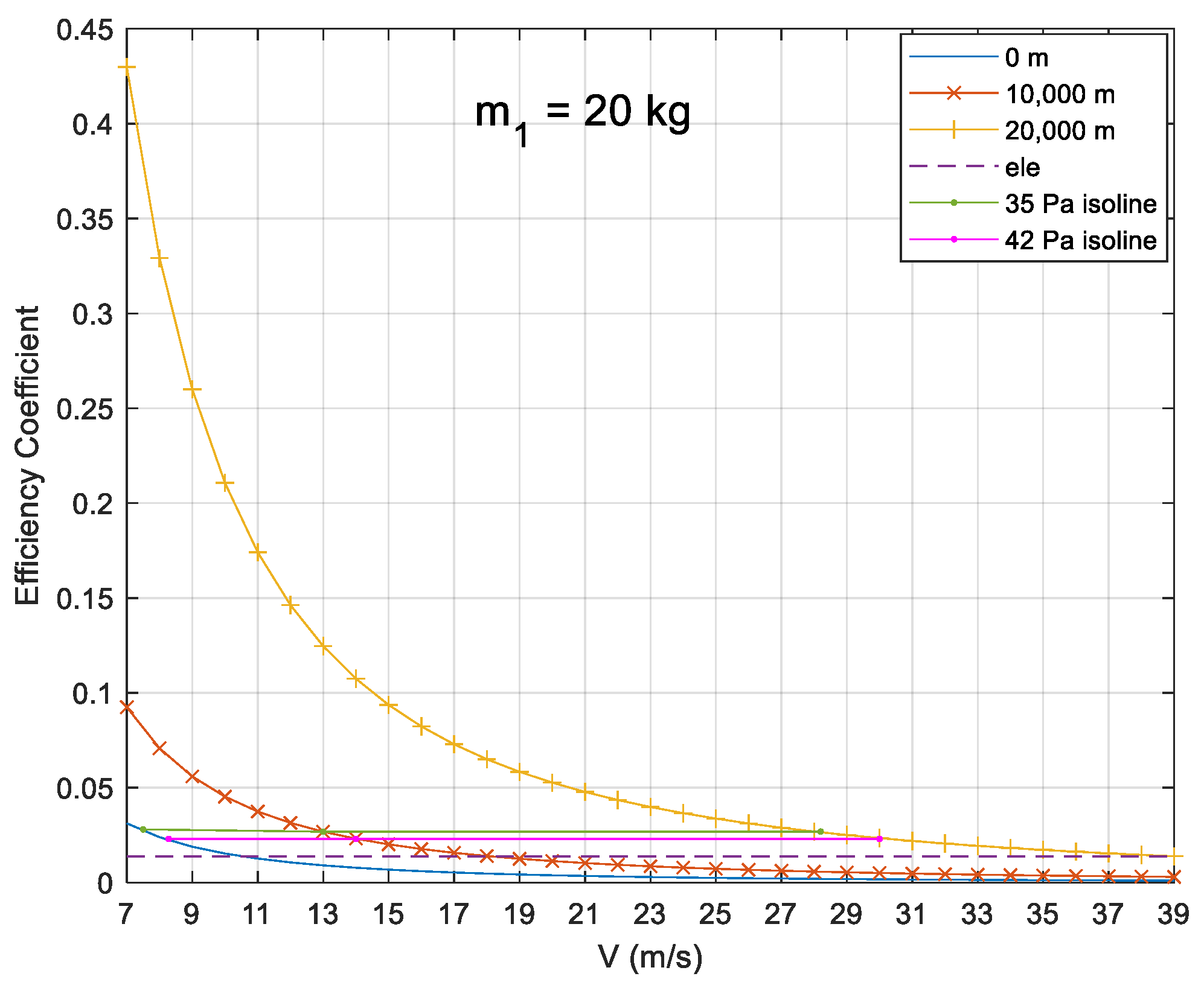
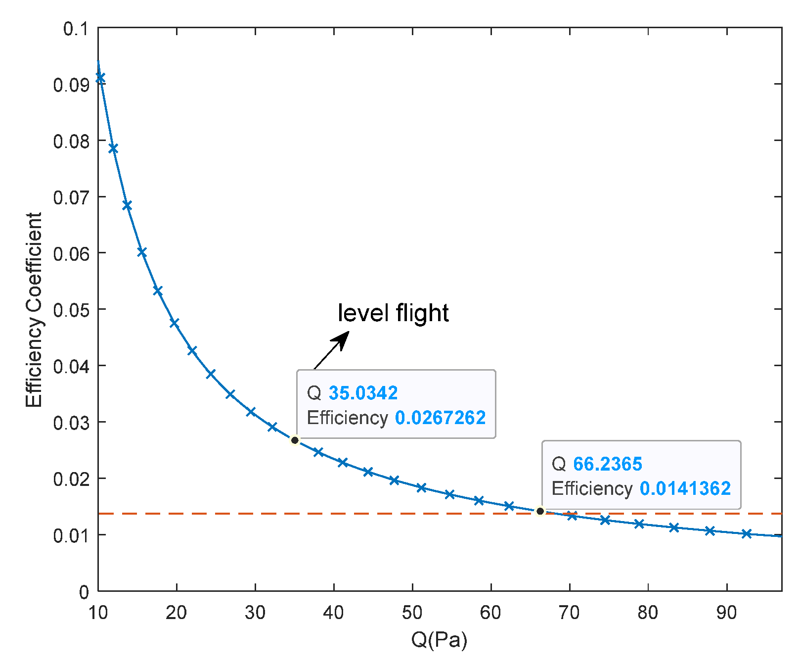
To measure the control efficiency of the MMC scheme, it was necessary to define a suitable evaluation index. In this regard, the slider efficiency coefficient applicable to the moving mass control scheme and the elevator efficiency coefficient applicable to the traditional pneumatic rudder surface control scheme were defined. The physical significance of the two is similar, where the former refers to the change value of the pitching moment coefficient caused by the unit slider offset. The expression is:
It can be seen in Equation (34) that the efficiency coefficient of the slider is inversely proportional to the square of the flight speed of the UAV; that is, the lower the speed of the UAV, the higher the control efficiency of the slider. Therefore, the MMC scheme has more advantages in high-altitude and low-speed conditions. However, for the traditional aerodynamic elevator control scheme, the efficiency coefficient of the elevator does not change significantly with the flight speed of the UAV, which can be approximately regarded as a constant value. For the object studied in this paper, its value was = 0.0137.
Figure 3 shows that, as expected, when the speed decreased, the efficiency coefficient of the slider changed sharply with the speed, and the change in its value gradually slowed down with the increase in the UAV’s flight speed. On the other hand, the efficiency coefficient of the slider increased significantly with the increase in altitude. Under the dynamic pressures needed for level flight of 35 Pa and 42 Pa at the altitudes of 0 m, 10,000 m, and 20,000 m, for the MMC scheme (20 kg), the efficiency coefficient was 200% of that of elevator scheme. Therefore, the longitudinal MMC scheme proposed in this paper is suitable for HALE UAVs in high-altitude and low-speed conditions and can realize efficient control of such UAVs.
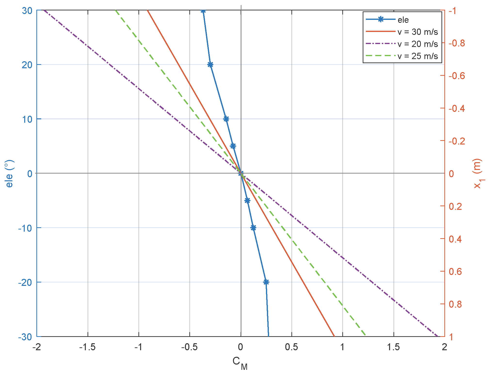
The elevator’s efficiency was directly related to its deflection angle, and when the deflection exceeded 20°, the efficiency coefficient would appear nonlinear due to the significant airflow separation phenomenon. For the MMC, according to Equation (34), the efficiency coefficient did not change with the displacement of the slider, which allowed the MMC to avoid the nonlinear efficiency. The stable pitch control moment made the MMC superior to the elevator in control efficiency. At the same time, the pitch moment coefficient of the MMC was also significantly higher than that of the elevator scheme and could reach 200–1000% of the elevator scheme at a speed of 20–30 m/s (
Figure 4). Therefore, the MMC scheme can achieve pitch control equivalent to elevator scheme by moving the slider within 10% of the fuselage length. Furthermore, by expanding the movement range of the slider, the mass of the slider can be reduced to achieve smooth control or greater pitch control.
4. Modal Analysis Based on Numerical Simulation
Based on the small disturbance linearization model in Equation (30), the longitudinal motion stability, damping characteristics, and other basic attributes of the UAV under the MMC scheme could be analyzed by solving the characteristic roots of the state matrix
. Feature points were selected as the horizontal straight flight of the UAV with speed V = 26.5563 m/s. When the slider mass was selected as 20 kg, the characteristic roots of the state matrix
could be obtained as shown in
Table 1.
According to the classical control theory, the absolute value of the real part of the characteristic root determines the attenuation velocity of the system, which reflects the damping characteristics of the system itself. The stability of the system can be judged according to the positive or negative value of the real part of the characteristic root. The absolute value of the imaginary part of the characteristic root determines the oscillation angular frequency of the system itself and reflects the frequency characteristics of the system itself. The half-value time t
1/2 describes the time required for the modal motion parameters to change to half of the initial values. The oscillation number N
1/2 in the half-value time reflects the relationship between the frequency and damping. A greater value means the oscillation frequency is too high or the damping is too small. It can be seen in
Table 1 and
Table 2 that the t
1/2 of the MMC scheme was smaller (that is, the convergence was faster), and the N
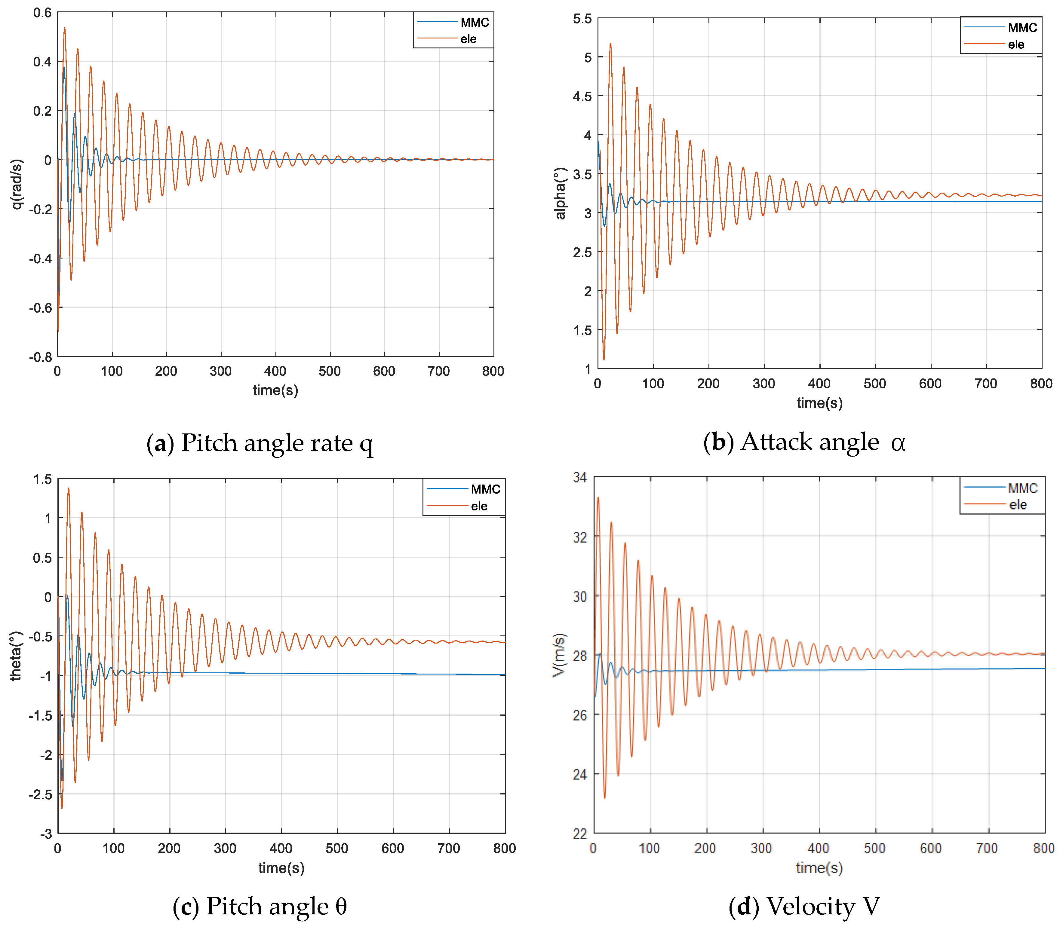
1/2 was also smaller, indicating a lower oscillation frequency and more appropriate damping. Because the five parameters in Equation (33) were different from the fixed values of the elevator scheme, the system moment of inertia changed in the anti-disturbance balancing process, which caused the change in these five parameters, which caused the UAV to resist the disturbance and restore the equilibrium state faster, and the system stability was higher. The step response in
Figure 5 can confirm that in the pitch channel, the MMC scheme could make the angle of attack
α, pitch rate
q, pitch angle
θ, and velocity
V converge faster and with fewer oscillations than the elevator scheme.
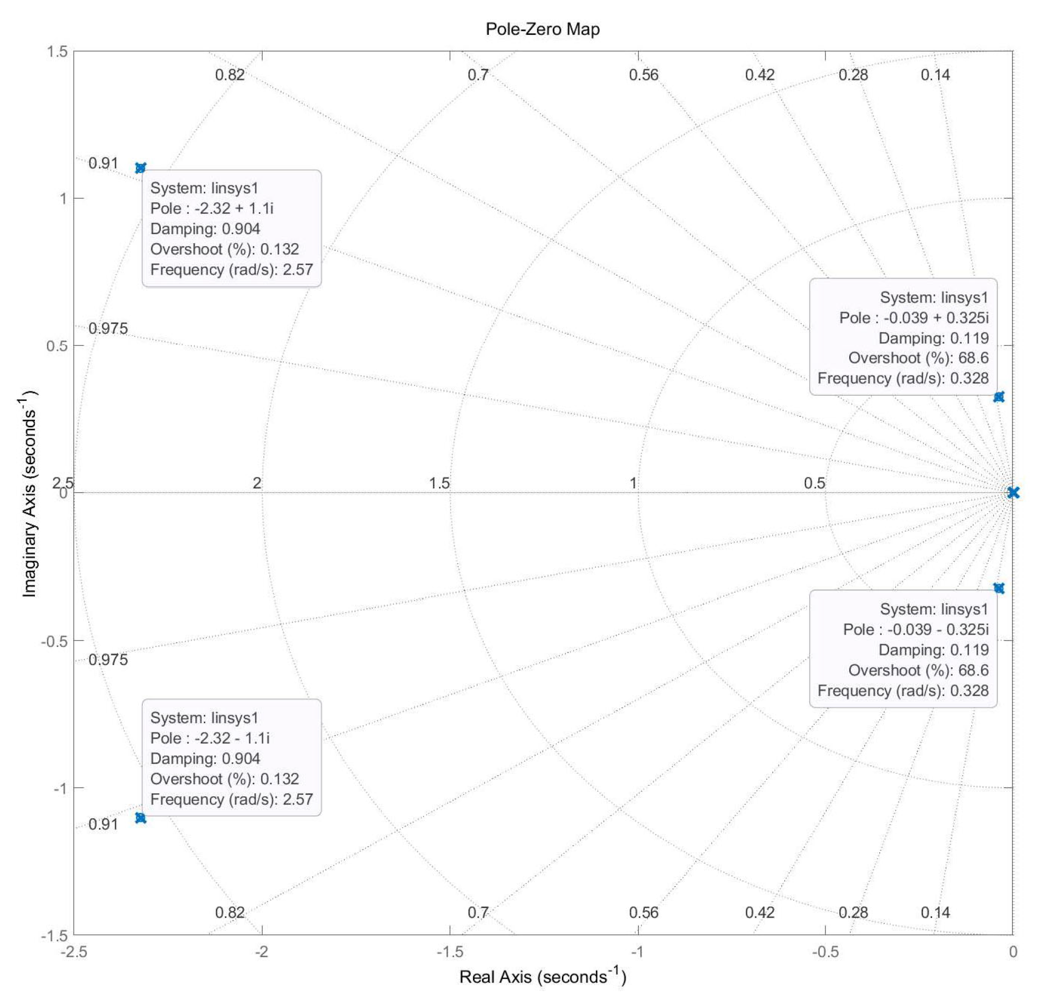
As shown in
Figure 6, the real parts of the characteristic roots were the same with REAL < 0 and IMAG ≠ 0. This indicates that the system was in a stable under-damped region, which means the moving slider could ensure the pitch stability of the UAV system.
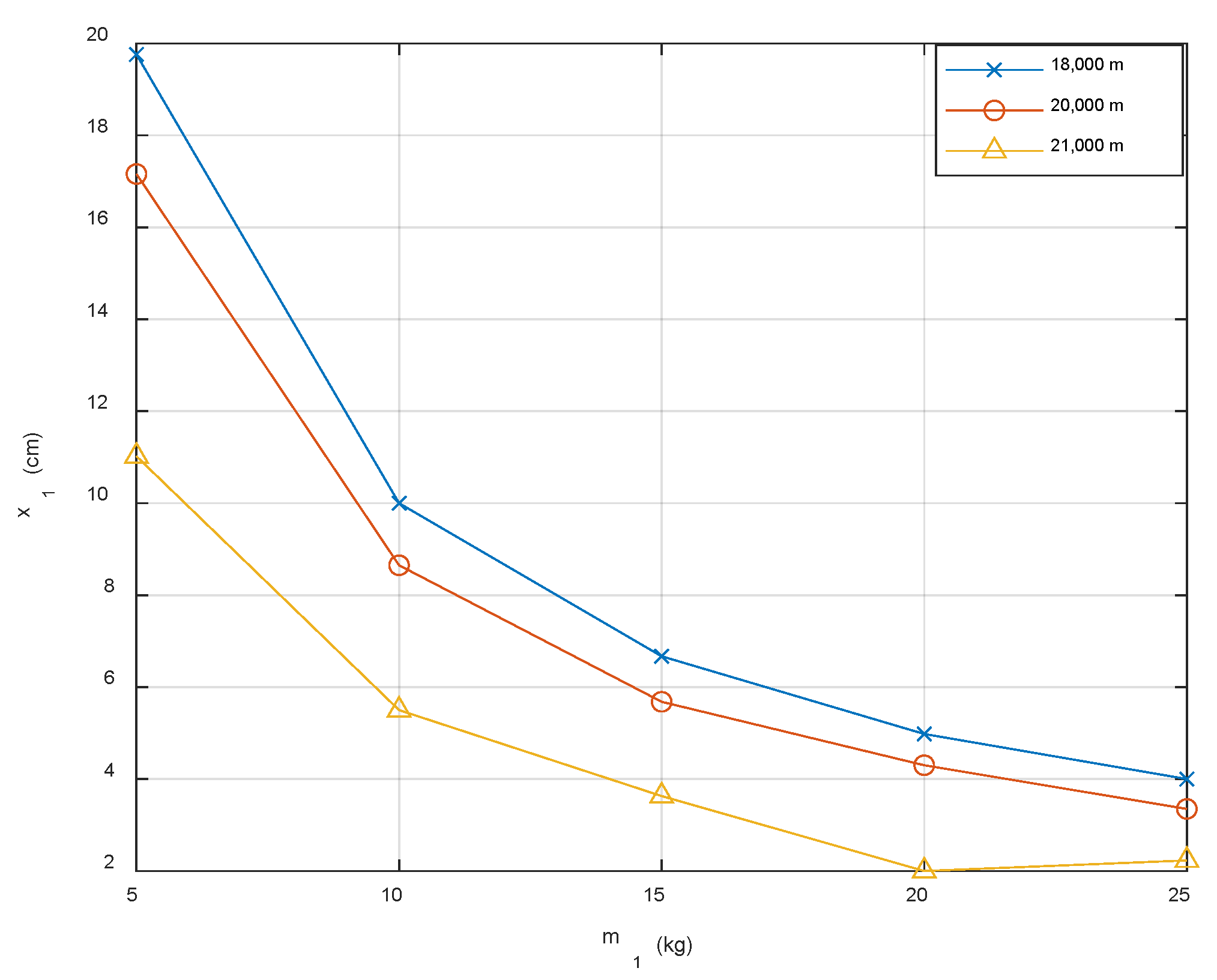
Furthermore, feature points were selected at different heights for trimming. It can be seen in
Figure 7 that with the increase in the height and mass of the slider, the movement of the slider required for trimming significantly decreased from 20 cm, which only accounted for 8% of the fuselage length, and this x
1 would significantly decrease to 4% of the fuselage length as the height decreased. This verifies the conclusion above that the MMC scheme is suitable for HALE UAVs in high-altitude and low-speed conditions.
The short period modal was mainly manifested in the initial stage of disturbance recovery, and
was approximately considered to be 0. Then, according to Equation (30), the tangential force equation was omitted, and the approximate equation mainly reflecting the characteristics of short-period mode could be obtained as:
and the characteristic equation could be expressed as:
According to the stability criterion of the second-order system, if the short period is stable, the coefficient of the characteristic equation must be greater than zero. By converting the conditions into dimensionless aerodynamic coefficients, the critical condition could be obtained as:
Furthermore, the critical condition could be derived as:
where
is the aerodynamic focus in the body frame.
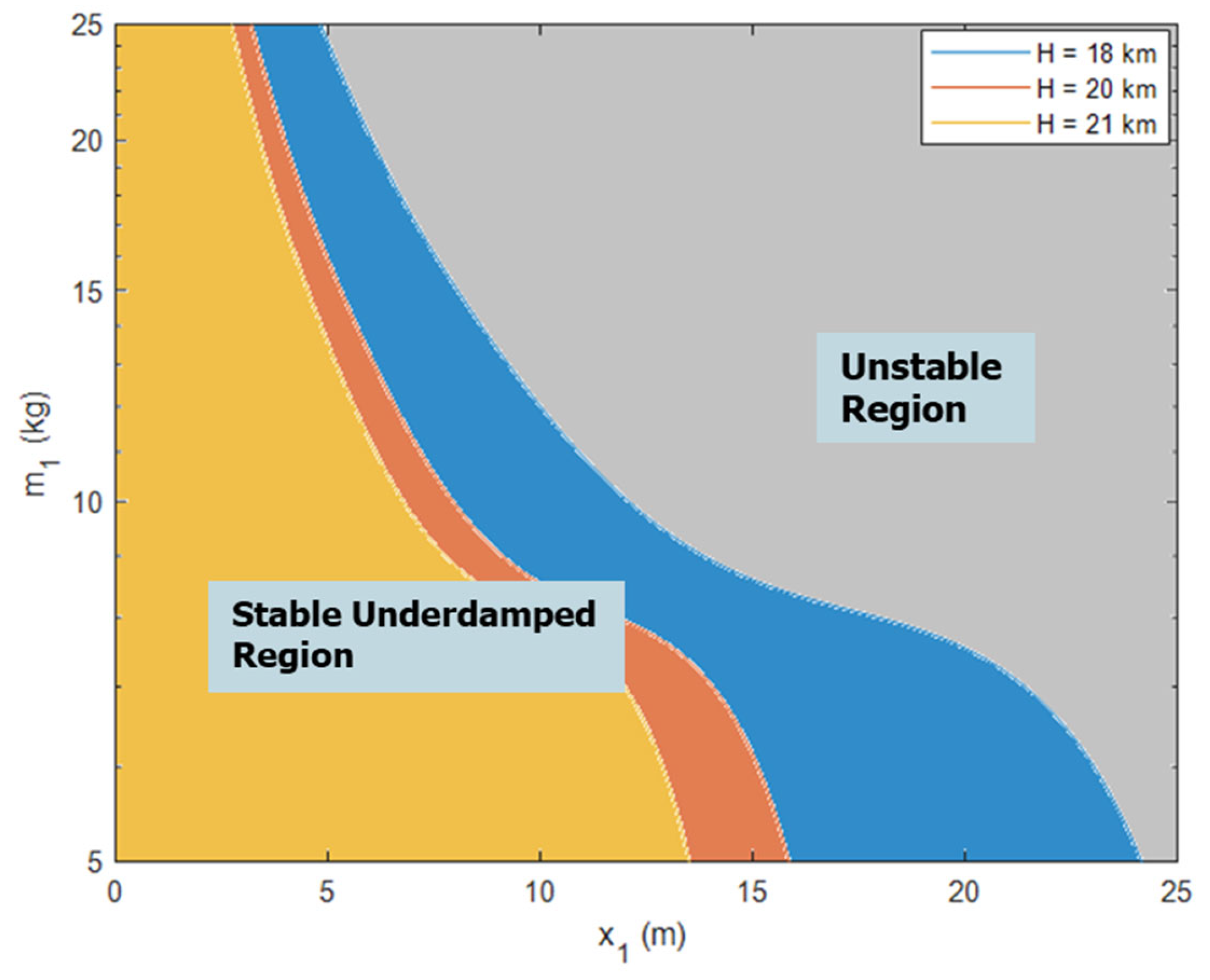
According to Equations (38)–(40), it can be concluded that the longitudinal short-period stability is related to the position of the slider, the air density, and the mass of the slider. Therefore, the longitudinal short-period dynamic characteristic distribution at different heights can be represented as shown in
Figure 8.
As can be seen in
Figure 8, with the increase in the flight altitude and mass of the slider, the stability region on the left gradually decreased. According to the stability margin, by increasing the moving distance of the slider, the mass of the slider in the MMC scheme can be appropriately reduced to lighten the entire system’s weight. However, within the control requirements of the UAV, the moving distance of the slider (
Figure 2) ranging within 20 cm before and after the mass center could keep the system in the stable region; that is, the stability margin was large enough.
Based on the above analysis of the handling characteristics, trim point characteristics, and longitudinal static stability margin, it can be seen that replacing the elevator scheme with the MMC scheme can significantly increase the pitch control torque by 200–1000%. In addition, with the increase in height, not only the control efficiency was significantly improved, but the moving distance of the sliding block required for trim also decreased from 20 cm at 18 km to 11 cm at 21 km, and the longitudinal static stability margin was extremely large.
5. Conclusions
In this paper, an MMC scheme was proposed to apply to the pitch control of HALE UAVs in high-altitude and low-speed conditions, and the slider was located in the UAV’s fuselage. The following conclusions can be stated:
(1) The movement of the slider led to the change in the system’s inertia and was coupled with the movement behavior of the slider itself.
(2) The control efficiency of the MMC scheme could reach 200% of the traditional elevator control scheme at cruise speed.
(3) The change in parameters in the state matrix and control matrix of the linearized equations resulted in a shorter half-amplitude time and a faster convergence for the long period in addition to a lower oscillation frequency for the short period of the MMC scheme. The numerical simulation results also proved that the MMC scheme had a sufficient stability margin in the HALE UAVs’ longitudinal control at high altitude and low speed.
Subsequent studies will develop the HALE UAVs’ control system based on MMC. In the design of an MMC system, the dynamic behavior of the moving mass and the aeroelasticity of the UAV must be considered in the design of the moving quality-control system. The combination of fuzzy logic and a neural network with PID control is expected to achieve this goal. An RBF neural network will be used to estimate the unknown parts of the UAV dynamics equations due to coupling, parameter perturbation, and external disturbance, and the controller will be designed based on the estimated values.


