
Quadcopter Drone for Vision-Based Autonomous Target Following


Abstract
:1. Introduction
- The tracking capability of the commercial miniature UAV is still immature [12,13]. The methods developed in the papers might not be applicable in real-world applications [14,15]. These methods are feasible, but are slightly restricted from the viewpoint of practical applications. For human target following, this research proposes an adaptive target identification system to resolve the problem when the specific target is in a crowd.
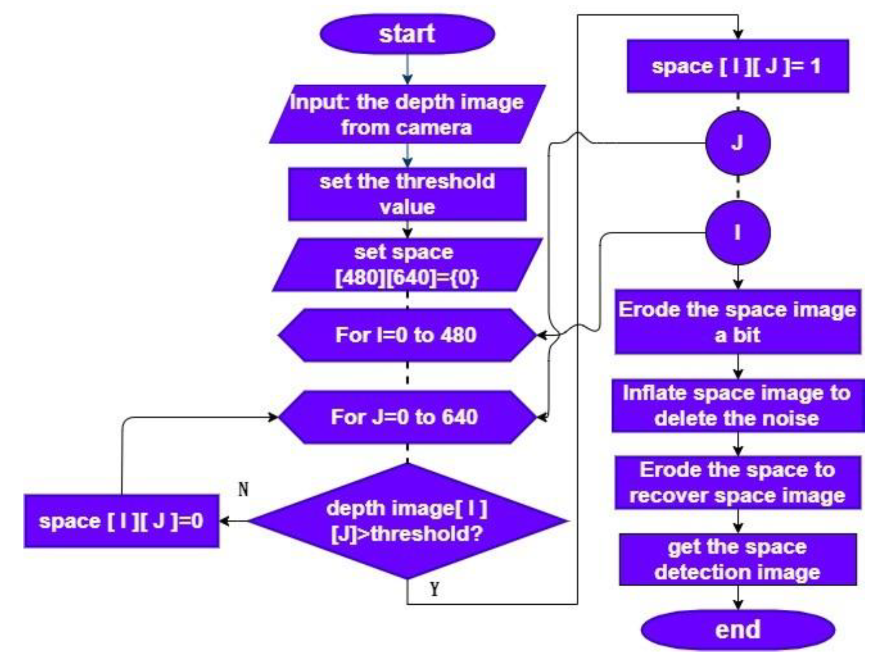
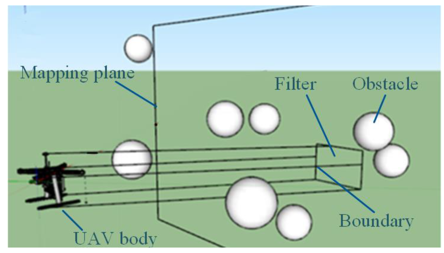
- The current UAV obstacle avoidance algorithms revealed in the papers were difficult to implement in the small-scale embedded system because of the large computational sizes. Here, we propose a novel contour and spiral convolution space detection (CASCSD) algorithm to tackle the issue. Through the emulated expansion and etching of the image processing, we can filter out noises while enlarging imaging signals to indicate that if the obstacles might interfere with the flight path. This algorithm consumes less computational resources and is appropriate to be used in the current miniature UAV applications.
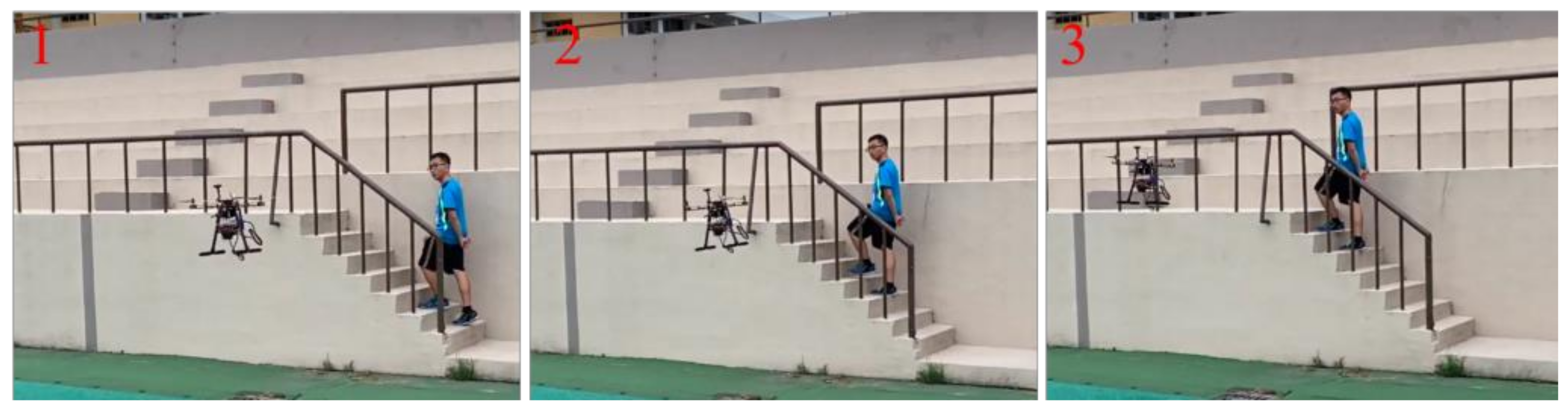
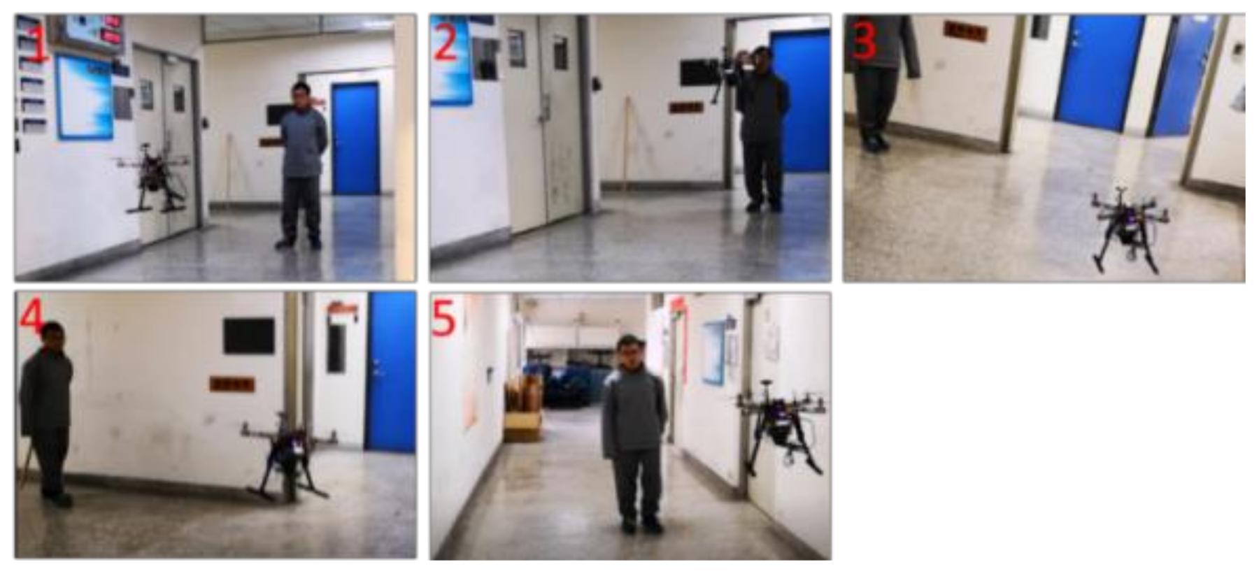
- Intelligent mobile assistants have recently become popular; however, UAVs moving inside a building, on stairs, or in rugged areas is still a challenge. A miniature UAV drone is one of the potential substitutes for work under these scenarios.
2. System Description
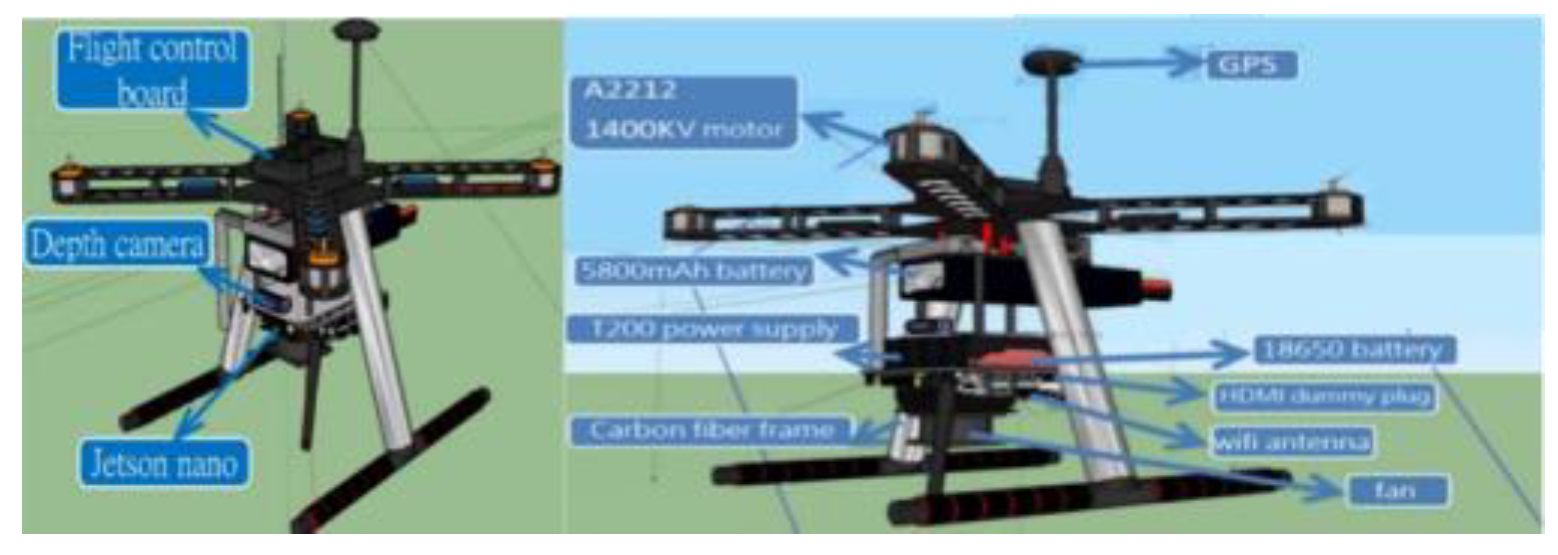
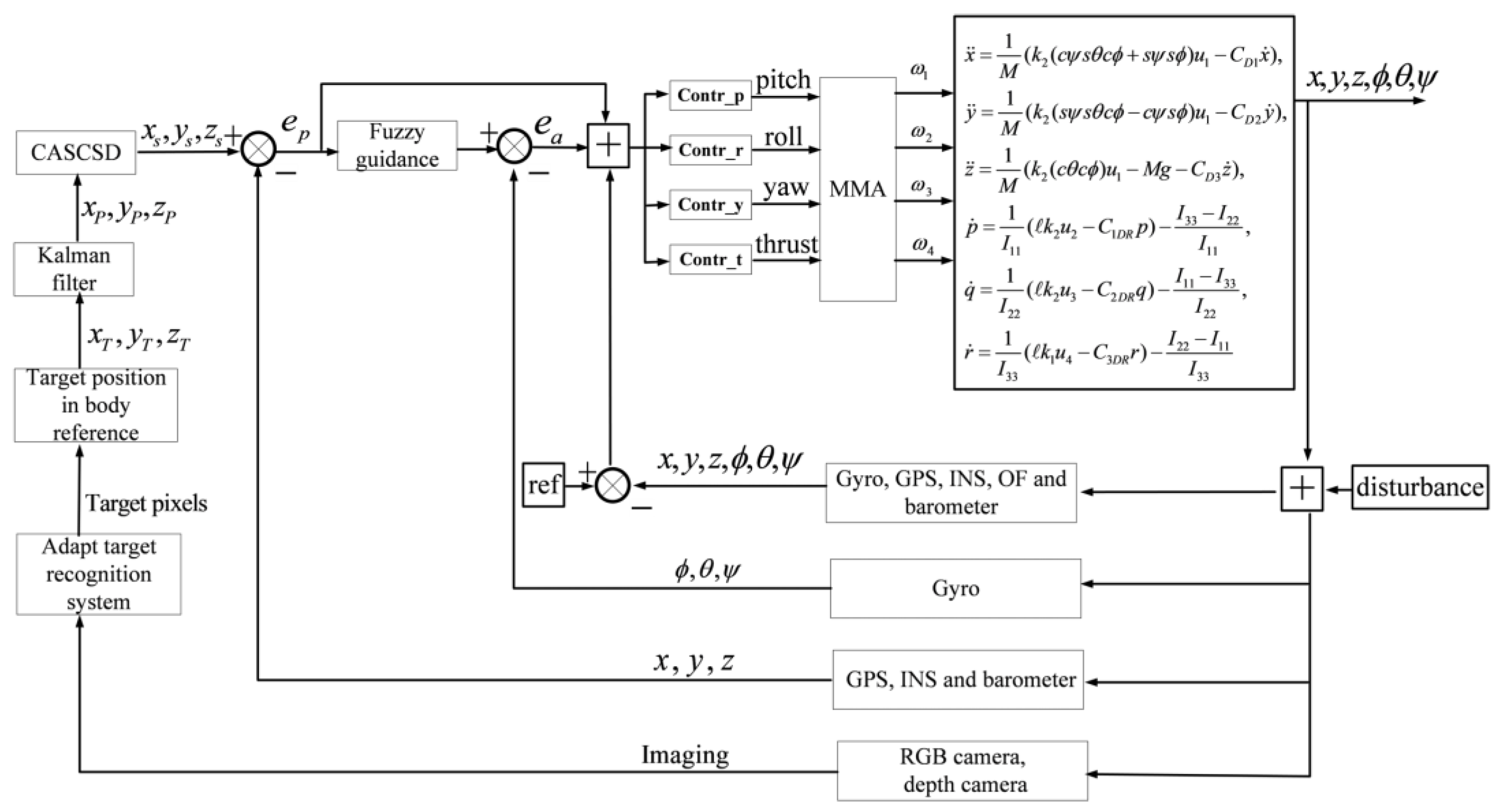
2.1. Architecture
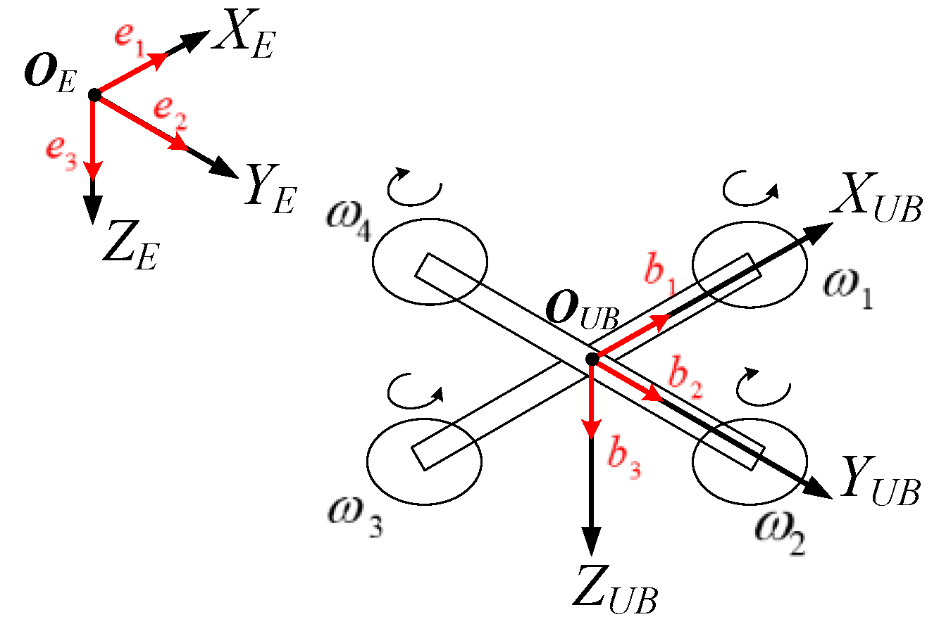
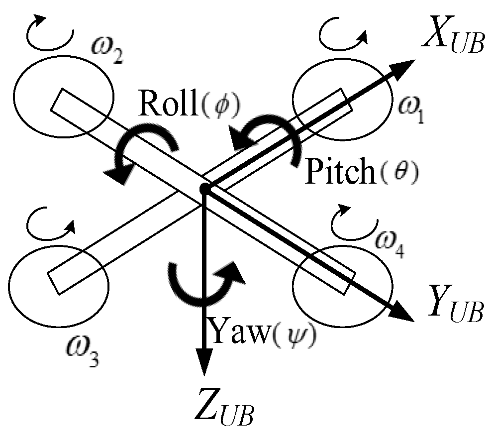
2.2. Modeling
Flight Dynamics Model (FDM) Description
3. Target Tracking and Obstacle Avoidance
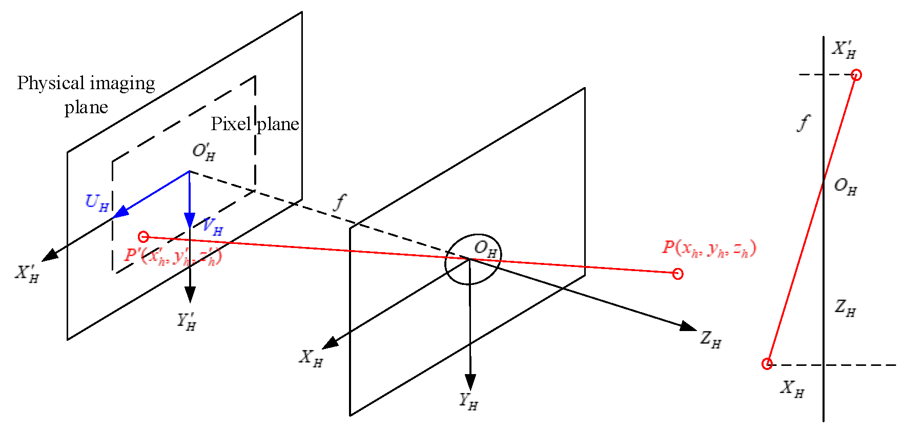
3.1. Calibration and Coordinate Conversion
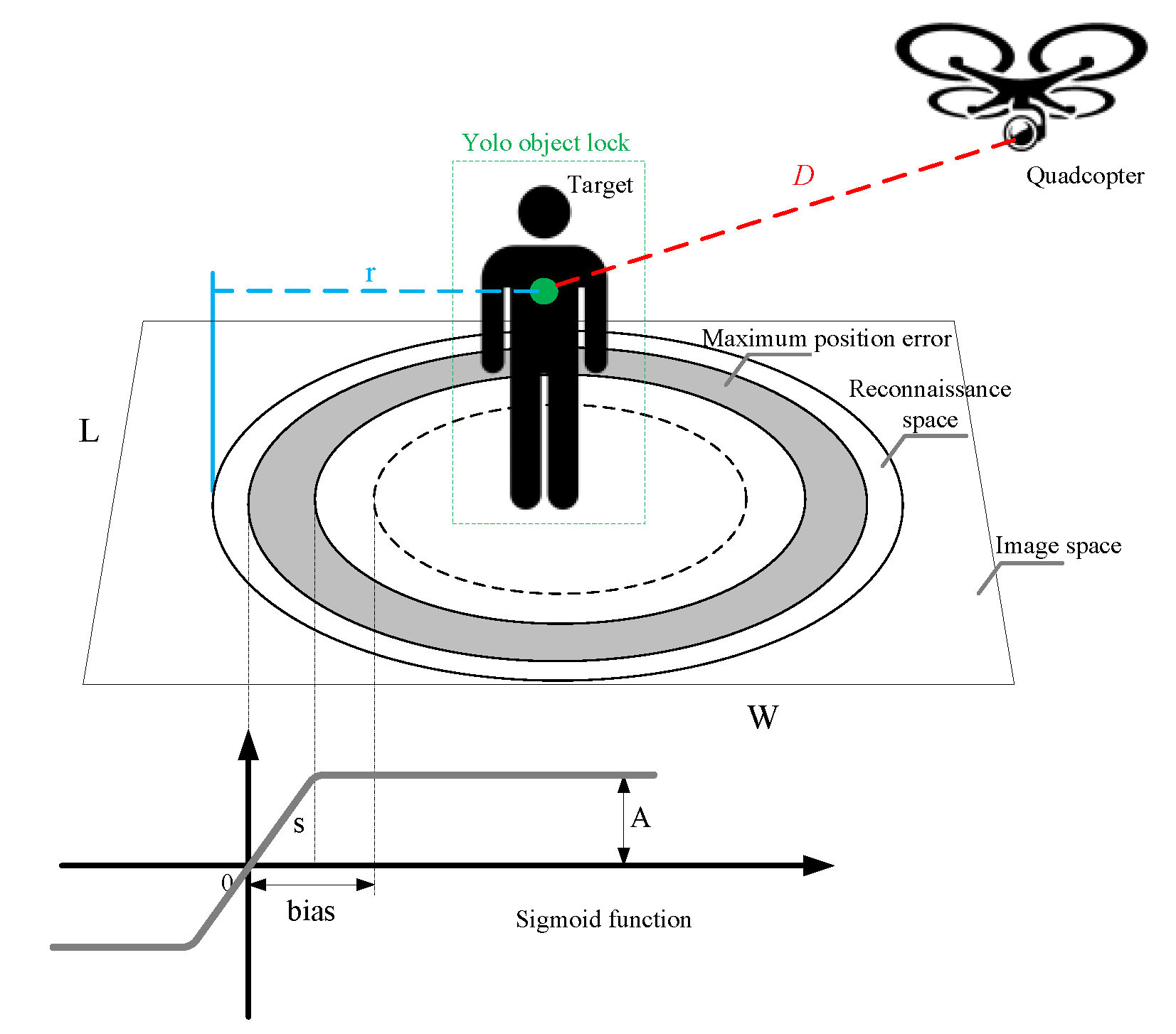
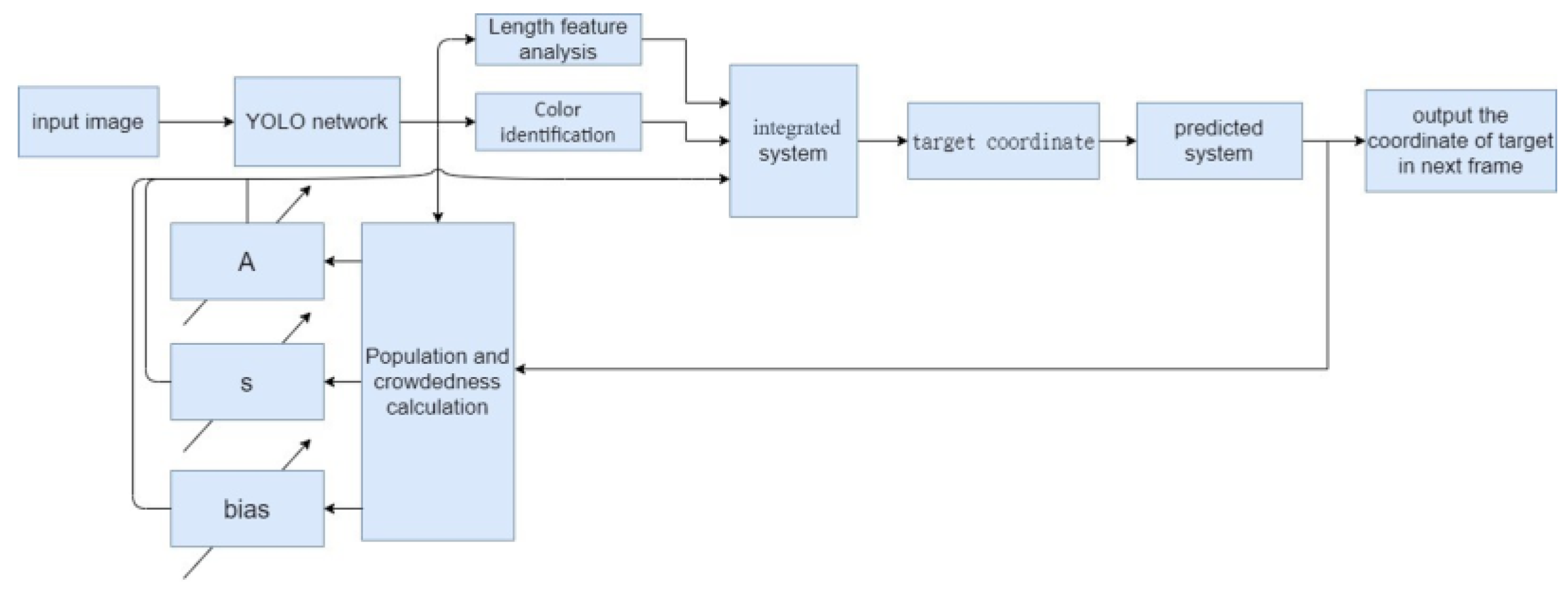
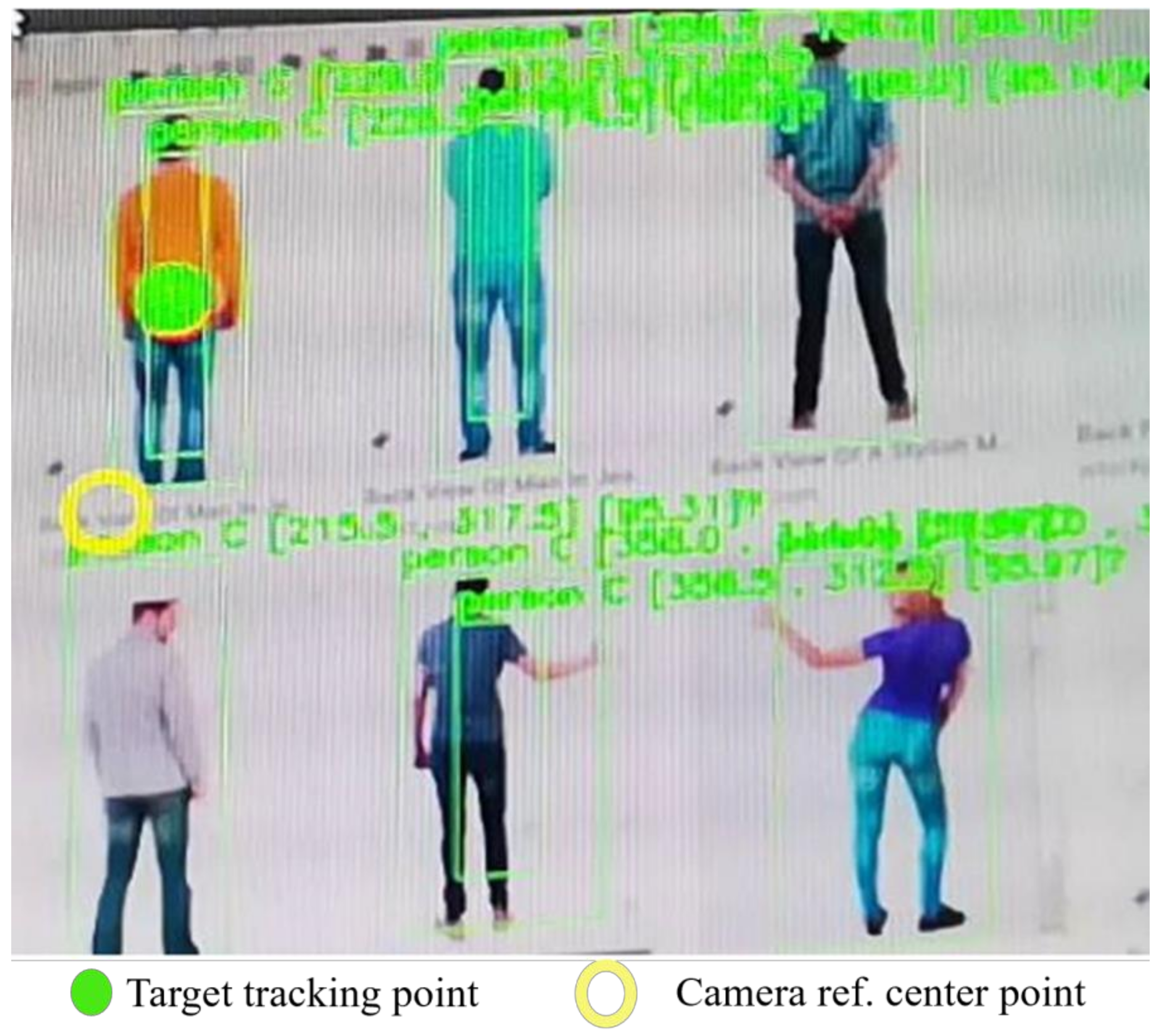
3.2. Dynamic Target ID and Locking
- There are many people that appear in the image. The bias is increased to reflect the noisy background.
- There are few people in the image, but they are tightly crowded. The bias is decreased and s is increased by increasing to rise discriminative sensitivity.
- There are many people, but they are widely dispersed. The bias is decreased to aid highlighting the target.
- There are few people and they are widely dispersed. The bias is set to zero and a large s is suggested to boost the discriminative effect.
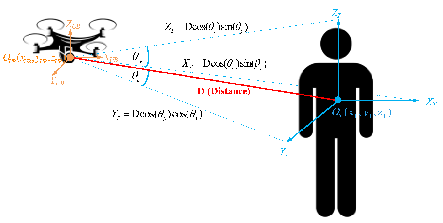
3.3. Target Positioning in 3D Space
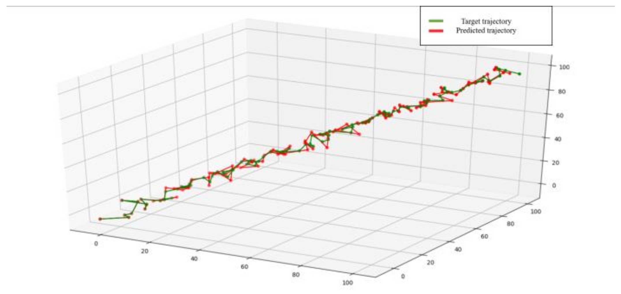
3.4. Target Movement Estimation
3.5. Flight Path Planning
4. Adaptive Cruise Control (ACC)
4.1. Thrust Force
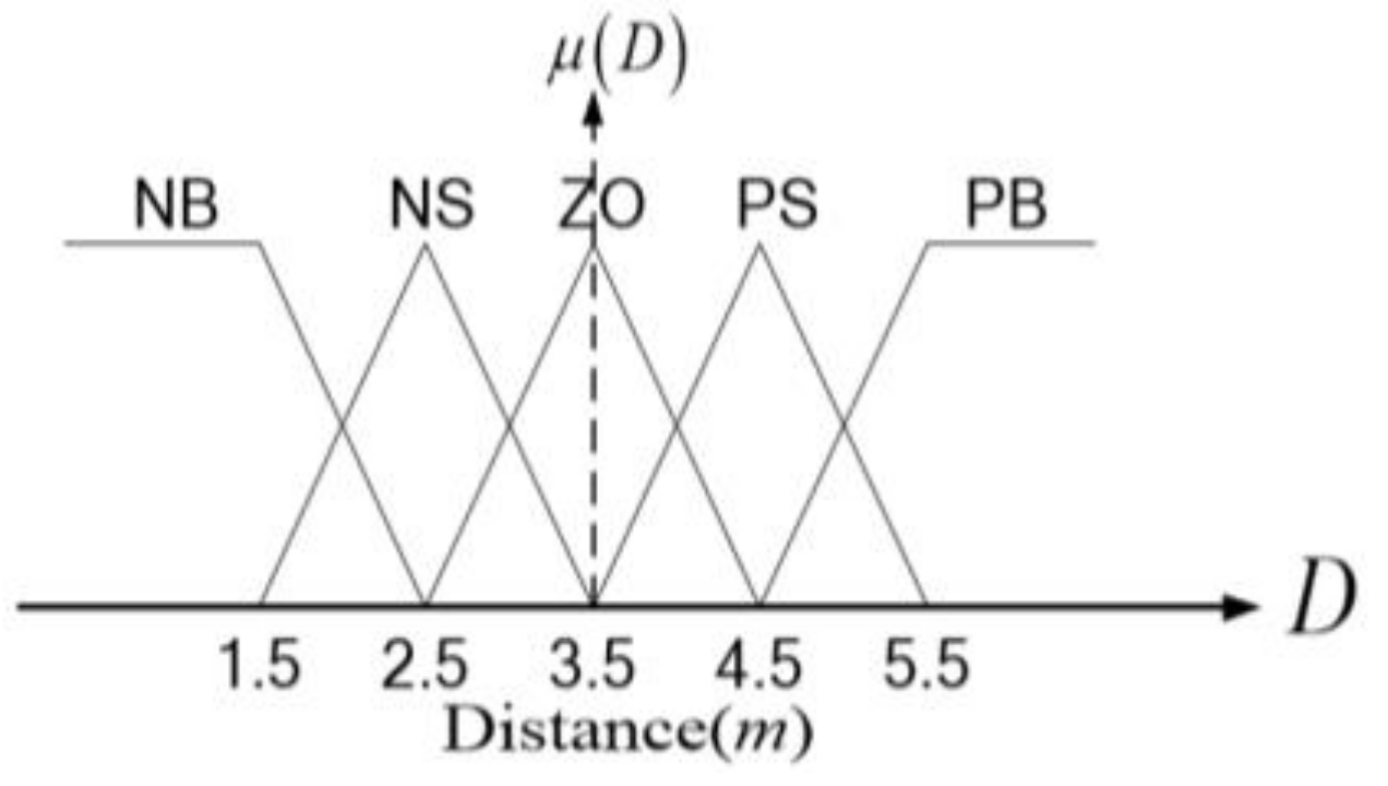
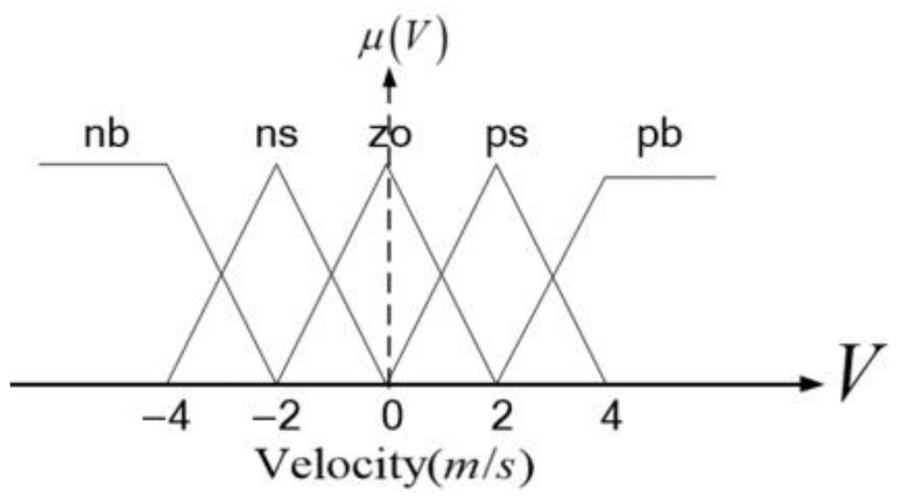
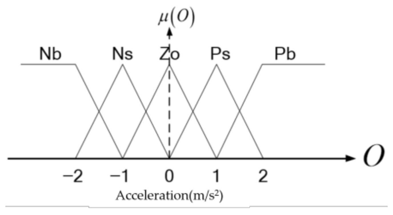
4.2. Fuzzy Control Implementation
5. Experimental Verification
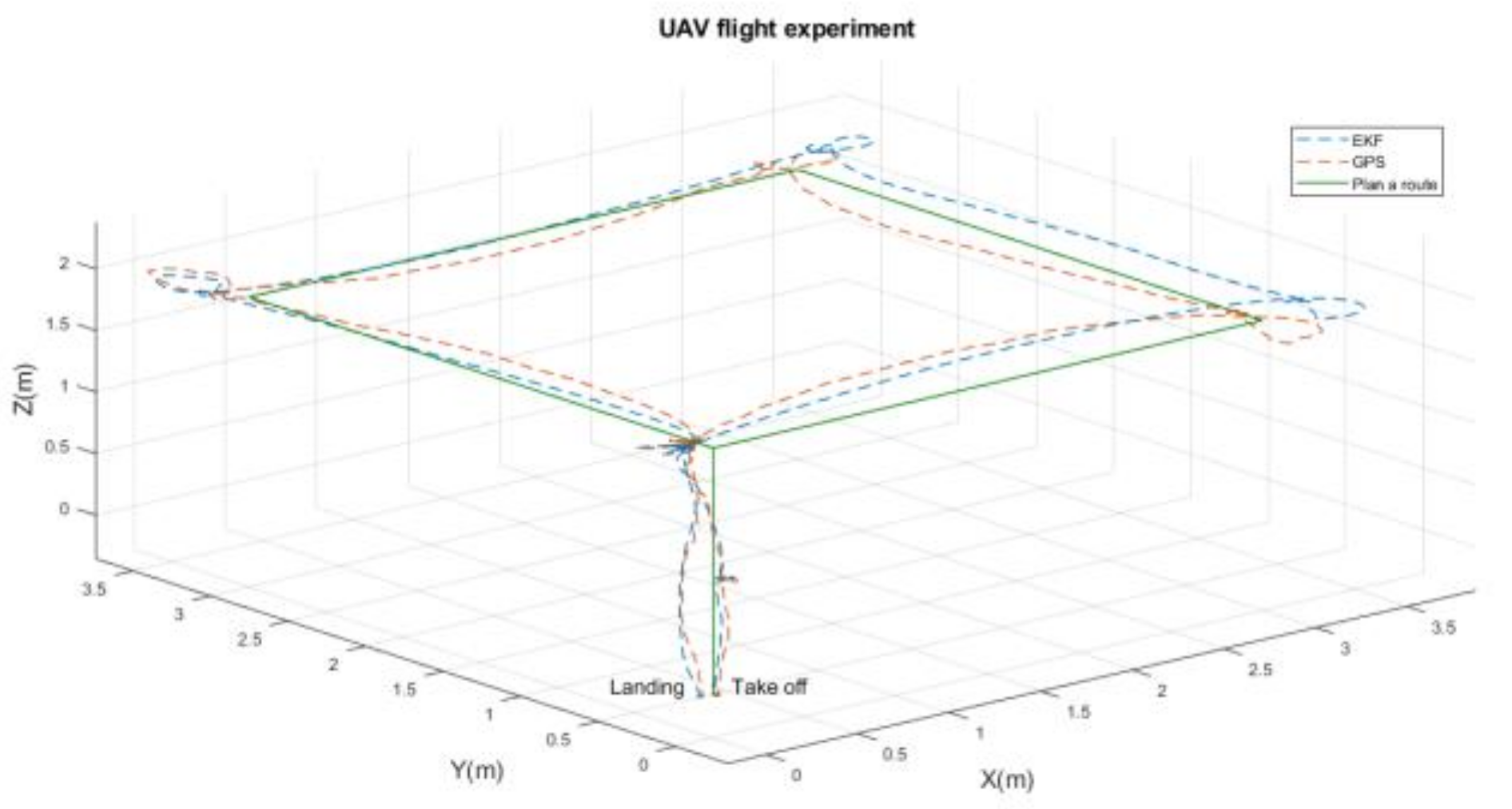
5.1. Autonomous Flight
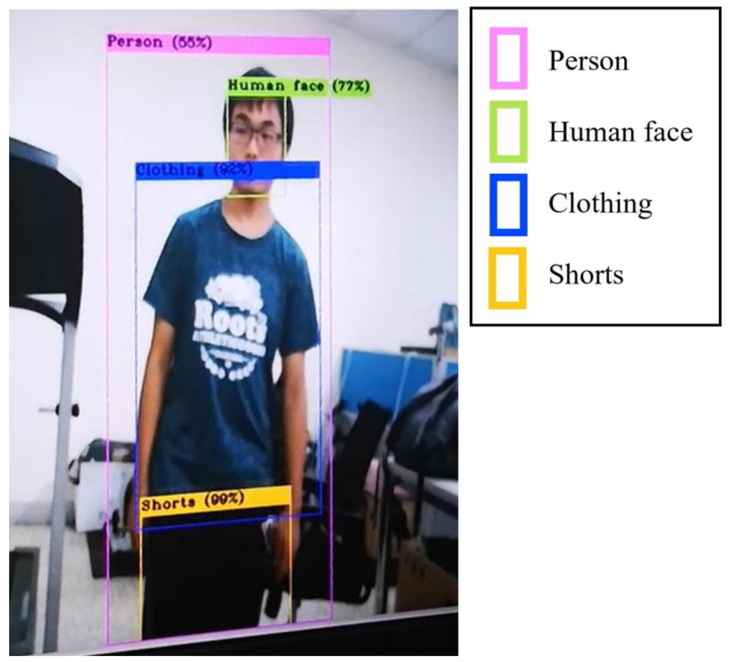
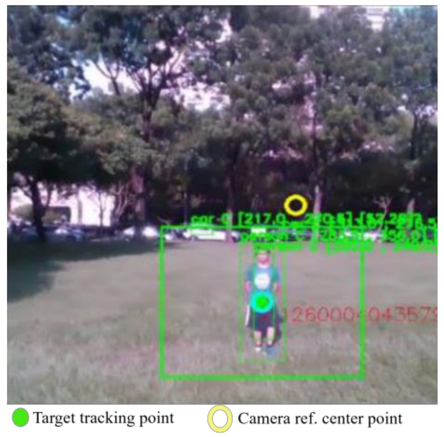
5.2. Target Identification
5.3. Estimation of Target Movement
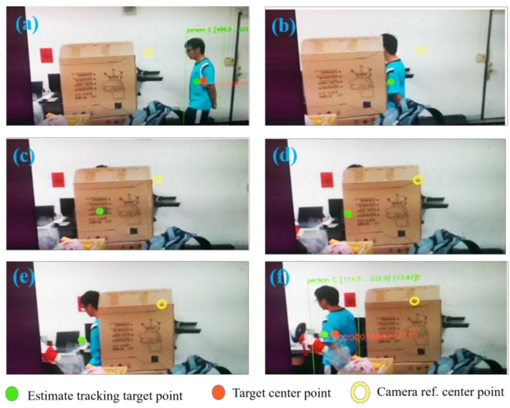
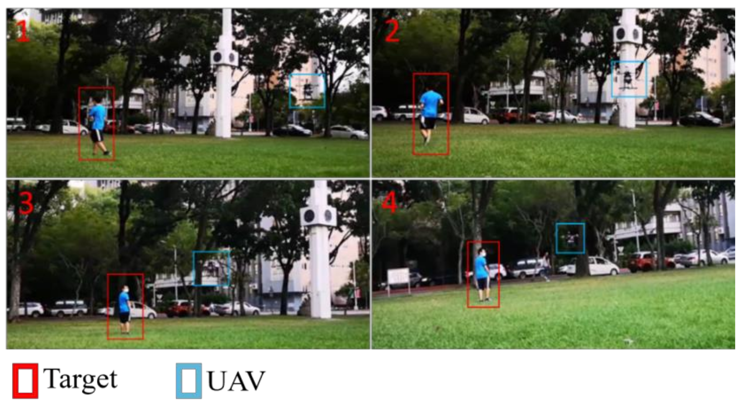
5.4. Dynamic Target Tracking
5.5. Feature Comparison
6. Conclusions
Author Contributions
Funding
Conflicts of Interest
Appendix A
References
- Karar, A.S.; Said, S.; Beyrouthy, T. Pepper Humanoid Robot as A Service Robot: A Customer Approach. In Proceedings of the 2019 3rd International Conference on Bio-engineering for Smart Technologies (BioSMART), Paris, France, 24–26 April 2019. [Google Scholar]
- Cuthbertson, A. Watch: Is Google’s New Two-Legged Robot the Soldier of the Future? In Newsweek; IBT Media: NY, USA, 2016. [Google Scholar]
- Ou, S.Q. Vision-based Path Planning and Control of a Mobile Robot Based on DNN Object Recognition and ORB-SLAM2. Master’s Thesis, National Chiao Tung University, Taiwan, 2019. [Google Scholar]
- Kiss, G. External Manipulation of Autonomous Vehicles. In Proceedings of the 2019 IEEE Smartworld, Ubiquitous Intelligence & Computing, Advanced & Trusted Computing, Scalable Computing & Communications, Cloud & Big Data Computing, Internet of People and Smart City Innovation, Leicester, UK, 19–23 August 2019. [Google Scholar]
- NTU. Singapore and Volvo Unveil World’s First Full Size, Autonomous Electric Bus. 2019. Available online: https://www.volvobuses.com/en/news/2019/mar/volvo-and-singapore-university-ntu-unveil-world-first-full-size-autonomous-electric-bus.html (accessed on 8 June 2020.).
- Jeong, H.Y.; Song, B.D.; Lee, S. The Flying Warehouse Delivery System: A Quantitative Approach for the Optimal Operation Policy of Airborne Fulfillment Center. IEEE Trans. Intell. Transp. Syst. 2020, 22, 7521–7530. [Google Scholar] [CrossRef]
- Palmer, A. Amazon Wins FAA Approval for Prime Air Quadcopter Delivery Fleet. In Consumer News and Business Channel; NBC Universal: Englewood Cliffs, NJ, USA, 2020. [Google Scholar]
- Yang, N.K.; San, K.T.; Chang, Y.S. A Novel Approach for Real Time Monitoring System to Manage UAV Delivery. In Proceedings of the 2016 5th IIAI International Congress on Advanced Applied Informatics, Kumamoto, Japan, 10–14 July 2016. [Google Scholar]
- Mechali, O.; Xu, L.; Xie, X.; Iqbal, J. Theory and practice for autonomous formation flight of quadrotors via distributed robust sliding mode control protocol with fixed-time stability guarantee. Control Eng. Pract. 2022, 123, 105150. [Google Scholar] [CrossRef]
- Chen, L.; Liu, Z.; Gao, H. Robust adaptive recursive sliding mode attitude control for a quadrotor with unknown disturbances. ISA Trans. 2022, 122, 114–125. [Google Scholar] [CrossRef] [PubMed]
- Guo, K.; Jia, J.; Yu, X.; Guo, L.; Xie, L. Multiple observers based anti-disturbance control for a quadrotor UAV against payload and wind disturbances. Control Eng. Pract. 2020, 102, 104560. [Google Scholar] [CrossRef]
- Qin, X.; Wang, T. Visual-based Tracking and Control Algorithm Design for Quadcopter UAV. In Proceedings of the 2019 Chinese Control and Decision Conference (CCDC), Nanchang, China, 3–5 June 2019. [Google Scholar]
- Zhang, W.; Song, K.; Rong, X.; Li, Y. Coarse-to-Fine UAV Target Tracking with Deep Reinforcement Learning. IEEE Trans. Autom. Sci. Eng. 2019, 16, 1522–1530. [Google Scholar] [CrossRef]
- Wang, Z.; Liu, Z.; Wang, D.; Wang, S.; Qi, Y.; Lu, H. Online Single Person Tracking for Unmanned Aerial Vehicles: Benchmark and New Baseline. In Proceedings of the ICASSP 2019–2019 IEEE International Conference on Acoustics, Speech and Signal Processing, Brighton, UK, 12–17 May 2019. [Google Scholar]
- Vasconcelos, F.; Vasconcelos, N. Person-Following Uavs. In Proceedings of the IEEE Winter Conference on Applications of Computer Vision, Lake Placid, NY, USA, 7–10 March 2016. [Google Scholar]
- Shen, Q.; Jiang, L.; Xiong, H. Person Tracking and Frontal Face Capture with UAV. In Proceedings of the IEEE 18th International Conference on Communication Technology, Chongqing, China, 8–11 October 2018. [Google Scholar]
- Singla, A.; Padakandla, S.; Bhatnagar, S. Memory-Based Deep Reinforcement Learning for Obstacle Avoidance in UAV with Limited Environment Knowledge. IEEE Trans. Intell. Transp. Syst. 2019, 22, 107–118. [Google Scholar] [CrossRef]
- Hou, J.; Zhang, Q.; Zhang, Y.; Zhu, K.; Lv, Y.; Yu, C. Low Altitude Sense and Avoid for MUAV Based on Stereo Vision. In Proceedings of the 2016 35th Chinese Control Conference, Chengdu, China, 27–29 July 2016. [Google Scholar]
- Li, B.W. Obstacle Detection and Collision Avoidance for Multicopters; National Central University: Taichung, Taiwan, 2017. [Google Scholar]
- Han, D.; Yang, Q.; Wang, R. Three-Dimensional Obstacle Avoidance for UAV Based on Reinforcement Learning and RealSense. J. Eng. 2020, 13, 540–544. [Google Scholar] [CrossRef]
- Zheng, Z.; Yao, H. A Method for UAV Tracking Target in Obstacle Environment. In Proceedings of the 2019 Chinese Automation Congress, Hangzhou, China, 22–24 November 2019. [Google Scholar]
- Wang, Y.; Wang, H.; Lun, Y. Shortest Path Planning of UAV for Target Tracking and Obstacle Avoidance in 3D Environment. In Proceedings of the Chinese Control Conference, Shenyang, China, 27–30 July 2020. [Google Scholar]
- Heidari, A.; Navimipour, N.J.; Unal, M.; Zhang, G. Machine Learning Applications in Internet-of-Drones: Systematic Review, Recent Deployments, and Open Issues. ACM Comput. Surv. 2022. [Google Scholar] [CrossRef]
- Tanaka, S.; Asignacion, A.; Nakata, T.; Suzuki, S.; Liu, H. Review of Biomimetic Approaches for Drones. Drones 2022, 6, 320. [Google Scholar] [CrossRef]
- Guo, K.; Tang, P.; Wang, H.; Lin, D.; Cui, X. Autonomous Landing of a Quadrotor on a Moving Platform via Model Predictive Control. Aerospace 2022, 9, 34. [Google Scholar] [CrossRef]
- Tian, X.; Jia, Y.; Luo, X.; Yin, J. Small Target Recognition and Tracking Based on UAV Platform. Sensors 2022, 22, 6579. [Google Scholar] [CrossRef]
- Solak, S.; Bolat, E.D. A new hybrid stereovision-based distance-estimation approach for mobile robot platforms. Comput. Electr. Eng. 2018, 67, 672–689. [Google Scholar] [CrossRef]
- Li, B.; Wu, Y. Path Planning for UAV Ground Target Tracking via Deep Reinforcement Learning. IEEE Access 2020, 8, 29064–29074. [Google Scholar] [CrossRef]
- Henkel, P.; Lamm, M.; Mittmann, U.; Fritzel, T.; Strauß, R.; Steinert, H.-J.; John, M. Verification of RTK Positioning of UAVs with High-Precision Laser Tracker. In Proceedings of the 2022 16th European Conference on Antennas and Propagation (EuCAP), Madrid, Spain, 27 March–1 April 2022. [Google Scholar]
- Gao, S.; Zhang, T. 14 Lectures on Visual SLAM; Publishing House of Electronics Industry: Beijing, China, 2017. [Google Scholar]
- Zhang, Z. A flexible new technique for camera calibration. IEEE Trans. Pattern Anal. Mach. Intell. 2000, 22, 1330–1334. [Google Scholar] [CrossRef] [Green Version]
- Redmon, J.; Farhadi, A. Yolov3: An Incremental Improvement. arXiv 2018, arXiv:1804.02767. [Google Scholar]
- Chen, W.C. Design and Implementation of an Intelligent UAV. Master’s Thesis, National Chung Hsing University, Taiwan, 2021. [Google Scholar]
- Huang, Q. Mathematical Modeling of Quadcopter Dynamics; Rose-Hulman Scholar: Terre Haute, IN, USA, 2016. [Google Scholar]


| O | D | |||||
|---|---|---|---|---|---|---|
| Nb | Ns | Zo | Ps | Pb | ||
| nb | Pb | Pb | Ps | Ps | Zo | |
| ns | Pb | Ps | Ps | Zo | Ns | |
| V | zo | Ps | Ps | Zo | Ns | Ns |
| ps | Ps | Zo | Ns | Ns | Nb | |
| pb | Zo | Ns | Ns | Nb | Nb | |
| Object No. | 1 | 2 | 3 |
|---|---|---|---|
| RR (%) | 99.7 | 41.0 | 7.5 |
| Object No. | 4 | 5 | 6 |
| RR (%) | 41.0 | 15.1 | 5.2 |
| Comparator | Application Field | Functional Narrative |
|---|---|---|
| This article | Indoor, outdoor (low altitude), stairwell | Identify by clothing; available for crowd, tracking, and obstacle avoidance |
| [15] | Indoor, outdoor (low altitude) | QR-code identification (strict conditions), tracking but no obstacle avoidance |
| [23] | Outdoor (high altitude) | Recognition and tracking functions are used for drones to park on the landing zone on the roof of the car |
| [24] | Outdoor (high altitude) | UAVs identify and track targets at a high altitude |
| [26] | Indoor | Use 3D vision to measure the distance between UAVs and objects (can be used for obstacle avoidance) |
| [28] | Outdoor | Using deep learning and simulating multiple UAV tracking and obstacle avoidance (simulation only) |
Disclaimer/Publisher’s Note: The statements, opinions and data contained in all publications are solely those of the individual author(s) and contributor(s) and not of MDPI and/or the editor(s). MDPI and/or the editor(s) disclaim responsibility for any injury to people or property resulting from any ideas, methods, instructions or products referred to in the content. |
© 2023 by the authors. Licensee MDPI, Basel, Switzerland. This article is an open access article distributed under the terms and conditions of the Creative Commons Attribution (CC BY) license (https://creativecommons.org/licenses/by/4.0/).
Share and Cite
Chen, W.-C.; Lin, C.-L.; Chen, Y.-Y.; Cheng, H.-H. Quadcopter Drone for Vision-Based Autonomous Target Following. Aerospace 2023, 10, 82. https://doi.org/10.3390/aerospace10010082
Chen W-C, Lin C-L, Chen Y-Y, Cheng H-H. Quadcopter Drone for Vision-Based Autonomous Target Following. Aerospace. 2023; 10(1):82. https://doi.org/10.3390/aerospace10010082
Chicago/Turabian StyleChen, Wen-Chieh, Chun-Liang Lin, Yang-Yi Chen, and Hsin-Hsu Cheng. 2023. "Quadcopter Drone for Vision-Based Autonomous Target Following" Aerospace 10, no. 1: 82. https://doi.org/10.3390/aerospace10010082