Article

Numerical Simulations on the Performance of Two-Dimensional Serpentine Nozzle: Effect of Cone Mixer Angle and Aft-Deck

by
Hamada Mohmed Abdelmotalib Ahmed
1,*,
Byung-Guk Ahn
2 and
Jeekeun Lee
3
1
Department of Mechanical Power and Energy Engineering, Faculty of Engineering, Minia University, Minia 61511, Egypt
2
School of Advanced Materials Engineering, College of Engineering, Jeonbuk National University, Jeonju-si 54896, Republic of Korea
3
Division of Mechanical System Engineering, Jeonbuk National University, Jeonju-si 54896, Republic of Korea
*
Author to whom correspondence should be addressed.
Aerospace 2023, 10(1), 76; https://doi.org/10.3390/aerospace10010076
Submission received: 5 December 2022 / Revised: 24 December 2022 / Accepted: 9 January 2023 / Published: 11 January 2023
(This article belongs to the Special Issue Thermal Fluid Dynamics and Control in Aerospace)

Abstract

:
The current study addresses the effect of different designs of the exhaust mixer and aft-deck on the performance of a two-dimensional convergent nozzle represented by the internal and external flows and heat transfer process. The effect of different exhaust mixer cone angles of 10°, 15°, and 20°, and different aft-deck lengths of 140 mm, 280 mm, and 420 mm on the nozzle performance was investigated. To address the effect of an aft-deck, the flow behavior of a nozzle with an aft-deck was compared to that of a nozzle without an aft-deck. Then, the effect of different aft-deck lengths and different aft-decks with rectangular and trapezoid shapes was investigated. The results demonstrated that increasing the mixer cone angle resulted in decreasing the high-temperature core flow and increasing the low-temperature bypass flow. Increasing the mixer cone angle resulted in reducing the velocity inside the nozzle and at the exhausted jet, which can reduce the noise generated by the engine. Furthermore, increasing the mixer cone angle decreased the internal temperature of the nozzle and, along with the exhausted jet, decreased the infrared radiation. The results also illustrated that the presence of the aft-deck resulted in decreasing the pressure, temperature, and velocity inside the nozzle. The aft-deck also decreased the length and size of the potential core. The aft-deck length had no clear effect on the internal flow. However, increasing the aft-deck length resulted in a decrease in the exhaust gas temperature, which can decrease the infrared radiation. On another hand, using trapezoid and triangle aft-deck can enhance the performance of the nozzle by decreasing the velocity and temperature inside the nozzle and at the exhausted jet.

1. Introduction

An area of military application interest is stealth technology that needs to decrease infrared radiation and jet noise. The infrared radiation is mainly emitted by the walls of high-temperature including nozzle walls, the exit of the turbine, and the booster sleeve, in addition to hot gases generated from the exhaust system. About 90% of infrared radiation is provided by the exhaust nozzle and turbine section [1]. Therefore, the management and suppression of the infrared radiation of the exhaust system are very important to enhance the aircraft’s stealth performance [2,3]. There are various techniques that can be used to minimize infrared radiation. The most vital methods that are used in almost all military aircraft include using a jacket in cold water around the exhaust walls and using a material with low emissivity for coating the nozzle’s inner surface. However, using a jacket of cold-water results in extra weight problems on the aircraft, and using coating technology has a limitation on the capability of material heat resistance [4]. Moreover, a nozzle with a curved shape and rectangular or ellipse shape can be used to reduce both infrared radiation and jet noise. Serpentine nozzles are widely employed on different types of aircraft to increase survivability for their performance to suppress the infrared radiation signature. The curved shape of the serpentine nozzle can reduce the turbine exit’s high temperature. The serpentine nozzle can be used to decrease infrared radiation by 70%. Consequently, a serpentine nozzle has been used in a series of UAVs and stealth bombers to suppress the IR radiation resulting from an engine exhaust system [1]. The two-dimensional rectangular exit of the nozzle can intensify the mixing process between the hot jet and atmospheric air, which can reduce the size and length of the high-temperature potential core. The performance of the serpentine nozzle can be further improved by adding an aft-deck at the nozzle exit [5].
In the open literature, there are few studies [1,2,3,4,5,6,7,8,9,10,11,12,13,14,15,16,17,18,19,20,21,22,23] that investigate the flow characteristics of the serpentine nozzle. The double serpentine nozzle flow characteristics were numerically investigated by Xiao et al. [1]. The influence of the length ratio that defined the first S length to the second S length on the nozzle performance was studied. The Flow characteristics, such as total and static pressures, wall shear stress, and streamlines of the Mach number, were investigated. Compared to the axisymmetric nozzle, a double serpentine nozzle has different static pressure distribution at the lower walls and upper walls. The influence of the ratio of length to the diameter, aspect, and offset ratios on the infrared radiation and flow characteristics of the serpentine nozzle was studied by Yong et al. [2]. The study indicated that both thrust coefficient and total pressure recovery were first improved by increasing the offset ratio, and both parameters rapidly decreased. The friction and viscous losses resulting from stream vortices dominated the aerodynamic performance of the nozzle. The infrared radiation can be decreased by a higher 50% double S-shaped nozzle compared to the circular nozzle. Increasing the aspect and offset ratios can suppress the plume radiation. In another study by Xiao et al. [3], a numerical study was performed to study the effect of specific design parameters at the first serpentine exit on the flow field. Among the six different turbulent models used in this study, a shear-stress transport (SST) k-ω model achieved more accurate results and was used to simulate a serpentine nozzle flow. Increasing the width ratio W1/D increased the friction losses because of increasing the wetted perimeter, while small values of the width ratio resulted in increasing secondary flow losses. High flow velocity was induced in the first duct for a small area of the first serpentine duct. High local losses resulted from the steep offset distance of the first serpentine nozzle. These results demonstrated that the first serpentine duct width was recommended to range from one to three, and its area should be as large as possible, while the offset distance should be small. The serpentine nozzle friction losses were high because of the steep passage slope and rapid turning. Wen et al. [4] investigated the influence of engine swirl on the infrared radiation of the serpentine nozzle. The study results indicated the ability of engine swirl to suppress the infrared signature. The hot streak can be produced by the engine swirl, which can affect the infrared signature on the walls. The total infrared radiation could be reduced by 31.21% in the vertical plane and by 13.84% in the horizontal plane, compared to the engine without a swirl. An experimental study was conducted by Rajkumar et al. [5] to study the influence of pressure ratio on the flow characteristics in a single serpentine nozzle. The flow behavior was analyzed based on wall static pressure measurements and exhausted jet flow visualization. The pressure coefficient variation was symmetric, along with various pressure ratios. The flow of the core increased because the geometric transition resulted in transferring to sonic and supersonic flow. The symmetry of flow is reduced at the extension section exit with the constant area. The presence of an aft-deck can prevent barrel shock formation. In the study by Hamada et al. [6], the effect of different types of annular mixers on the performance of a two-dimensional nozzle was investigated. An annular mixer with different lengths of 140 and 280 mm, different diameters of 320 and 340 mm, and different shapes were used. The results indicated that decreasing the mixer diameter increased the cold bypass flow and improved the mixing between the hot core flow and cold bypass flow, which resulted in decreasing the temperature inside the nozzle and at the external jet. The mixer with a cone shape decreased the temperature inside the nozzle and increased it at the external jet. The results demonstrated that the best nozzle performance could be obtained using a smaller cylindrical mixer with a shorter length and a smaller diameter. Sun et al. [7] studied the effect of a serpentine nozzle on the bypass ratio of the turbofan engine exhaust and compared it to that of an axisymmetric nozzle. The results indicated that the bedded duct at the serpentine nozzle generated a pressure gradient in the streamline’s directions that resulted in a change in the flow through the bypass and core. Compared to the axisymmetric nozzle, the exhaust bypass ratio of the serpentine nozzle was higher by 8.1%. The impact of the shield ratio on the infrared radiation of the serpentine nozzle was studied by Wen et al. [8]. The infrared radiation of the serpentine and circular nozzles was numerically studied at various shield ratios. The results showed that, compared to the circular nozzle, the serpentine nozzle could reduce infrared radiation by 28.9. The complete nozzle shielding had no apparent advantages on the shielding ratio and infrared radiation, but it had a small influence on the serpentine nozzle outlet gases. The area ratio of double and single serpentine nozzles should be lower than 0.35 and 0.15, respectively, to achieve an effective reduction in the infrared radiation. The influence of aspect ratio on the flow characteristics of the double serpentine nozzle was studied by Sun et al. [9]. The aerodynamic performance based on internal flow and the external jet was numerically investigated for six different models of a nozzle with different aspect ratios of 3, 5, 7, 9, and 11. The variation in the lateral width leads to different pressure gradients and vortex distribution in the lateral direction. The length of the potential core was reduced by increasing the aspect ratio. The results demonstrated that an aspect ratio of five could achieve the best aerodynamic characteristics. The double serpentine nozzle flow characteristics for different inlet configurations were studied by Sun et al. [10]. The influence of strut setting angles and inlet swirl angles on the performance and flow field was also studied. The results indicated that the vortices found at the corner did not affect the tail con, struts, and bypass. There were differences in high-vorticity regimes of the core region due to the presence of a tail cone. Increasing strut setting angles and an inlet swirl angle resulted in reducing the high static temperature region. As the angles of the strut setting and inlet swirl increased, the serpentine nozzle decreased.
Most studies, including the above studies, focus on investigating the performance of the serpentine nozzle without considering the exhaust system, which exists in real turbofan engines. Furthermore, the utilization of the aft-deck can improve the nozzle performance by decreasing the external jet length and shielding the high-temperature sections, which can reduce IR radiation by 90% [16]. Therefore, this study investigates numerically the serpentine nozzle performance and considers the engine exhaust system and aft-deck. This study is an extension of a previous study [6] to achieve more understanding of the internal flow and exhausted jet characteristics of the nozzle. The effect of different mixer cone angles of 10°,15°, and 20° on the serpentine nozzle operation was studied. Then, the effect of an aft-deck on the flow characteristics and heat transfer process was studied. First, the nozzle performance of a nozzle with an aft-deck was compared to a nozzle without an aft-deck. Second, the influence of different aft-deck lengths of 140 mm, 280 mm, and 420 mm on the nozzle performance was studied. The simulation study was conducted using Commercial STAR CCM+ software via a three-dimensional model of the serpentine nozzle.

2. The Exhaust System Geometry

The exhaust system of an aircraft represents the main source of IR radiation in a band of 3–5 µm due to the large quantity of heat generated by the engine turbine, which increases the temperature of turbine entry above 2000 K [4]. Therefore, infrared radiation treatment requires more attention during the engine exhaust system design process. The exhaust system of the aircraft has two sections: the exhaust mixer and the nozzle section. The mixer part has double ducts called a bypass and core, as well as a mixer and tail cone. The exiting hot gases flow through the core, while low-temperature fluids flow through the bypass. The nozzle, as illustrated in Figure 1, has a curved shape with a circular inlet and an internal diameter of 470 mm, which is converted to a rectangular exit with a major and minor axis of 728 × 146 mm and hydraulic diameter (Dh) of 266 mm. The transformation from a circular inlet shape into a rectangular exit provides a serpentine shape so that the serpentine nozzle can shield the high-temperature parts. The serpentine nozzle was attached to a conical mixer with a length of 140 mm and diameter (D2) of 320 mm, and different cone angles (θ) of 10°, 15°, and 20°. The mixer is coupled with a central cone with a length of 280 mm and a diameter (D3) of 135 mm. The nozzle exit is attached to an aft-deck with a width of 728 mm with different lengths of 140 mm, 280 mm, and 420 mm, and different shapes.

3. Numerical Method

3.1. Numerical Model Setup

The three-dimensional model of the serpentine nozzle used in the simulation study is shown in Figure 2. A block with dimensions of 5 × 5 × 20 m was set as the computational flow domain to simulate the flow from the nozzle and the exhaust jet. The grid system shown in Figure 2 was used in the simulations, and the base size of the flow domain was 10 mm; for the nozzle wall, cone, and annular mixer, the mesh size was reduced to 0.5 mm. Two prism layers were used as the boundary cells with a total length of 0.5 mm. The bypass and core were considered pressure inlet boundary conditions with a uniform total temperature, pressure, and turbulence intensity. The nozzle exit was treated as a pressure outlet and subjected to atmospheric pressure and temperature. The walls of the nozzle were considered adiabatic walls, where the insulating material is typically used, and no-slip boundary conditions were considered. The SST (k-ω) turbulence model was used to model the flow inside the nozzle. For wall treatment, the all-y+ wall treatment was selected and provided the best results compared to other wall treatments provided by STAR CCM+ software. The all-y+ wall treatment is a hybrid treatment that uses a mixed wall function that emulates the high y+ wall treatment for coarse mesh and the low-y+ wall treatment for fine mesh. Consequently, the all-y+ wall treatment is relevant for a wide range of near-wall grid conditions. Table 1 summarizes the pressure and temperature values at different flow regions. The simulations were carried out using STAR CCM+ software, in which the equations were discretized with a finite volume method for each control volume. For spatial discretization, a second-order upwind scheme was used. The conservation equations of continuity, momentum, and energy were solved by using a coupled implicit flow solver in which the conservation equations are solved simultaneously as a vector of equations. The velocity field is obtained from the momentum equation, and the density is estimated from the equation of state. The flow inside the nozzle was treated as the ideal gas generated by mixing the high-temperature gases from the core with low-temperature gases from the bypass at high pressure, which results in different complicated features inside the nozzle. In this study, the flow-through core and bypass regions were considered air with the properties given in Table 2.
The flow characteristics inside the nozzle were determined at different locations in the axial direction (X), which were non-dimensionalized with the length of the nozzle (L). The axial locations of 0, 0.12, 0.26, 0.5, 0.78, and 1 were selected to evaluate the different flow characteristics. The axial location X/L = 0 refers to the nozzle inlet, the axial location X/L = 0.12 refers to the annular mixer end, the axial location X/L = 0.26 refers to the cone outlet, and the axial location X/L = 1 refers to the nozzle exit [6]. The variation of the nozzle frontal area along its length is shown in Figure 3. The frontal area is defined as the area projected along the fluid flow path to a plane perpendicular to the direction of motion. As illustrated by the figure, the frontal area gradually increased until it reached the axial location of 0.26 and then gradually reduced until the axial location of 0.78 before the nozzle area was almost the nozzle outlet.
For the grid independence study, three grids were used in the simulations with a total number of cells of one million and 200,150 cells, five million and 420,193 cells, and twelve million and 360,253 cells for the course, medium, and fine grids, respectively. Figure 4 indicates the flow characteristics inside the nozzle at different sections along the nozzle length for the different grids. As shown in the figure, both medium and fine grids have almost the same results indicating that at a certain cell size, the results are not affected by the cell size. To save the solution time, the medium grid is used in the simulations.

3.2. Model Validation

The simulation results were validated using the experimental results. The experimental procedure is mentioned in detail in the previous study [6]. The nozzle used in the experiments, as shown in Figure 5, was manufactured from a polylactic acid material using a technology of 3D printing and modeled using CATIA V5 software. The nozzle had an around inlet and rectangular exit attached with a rectangular aft-deck. To measure the wall static pressure, the nozzle thickness of 10 mm was used to attach the required pressure taps. The upper and lower wall pressures were measured using ten pressure taps connected to a microprocessor micro-manometer (FCO510) and LAB VIEW data acquisition software. The experiments were carried out at a temperature of 295 K and at an inlet air pressure of 0.25 bar. The experiments were repeated ten times, and the averaged values were considered. Figure 6 shows the profile of static pressure for the lower and upper walls of the nozzle. The figure indicates a good agreement between experimental and simulation results with a deviation of 5%. The method by Kline and Mcclintock [24] was selected for the uncertainty analysis.

4. Results and Discussion

4.1. Effect of the Mixer Cone Angle

The conical mixer has two flow areas: the core inlet, where the hot gases enter, and the bypass flow inlet, where cold air enters. The flow through the bypass region depends on the flow through the core region and the static pressure distribution at the conical mixer end. The ratio between the core and bypass flow rates is an important parameter that affects the operation of the nozzle. The values of the core and bypass flow rates at different mixer cone angles are given in Table 3. Despite all used models being subjected to the same inlet conditions, both the core and bypass flow rates varied with the variation in the mixer cone angle. Increasing the mixer cone angle resulted in reducing core flow rates and increasing bypass flow rates. The variation in the core and bypass flow rates is due to the variation in the static pressure at the end of the conical mixer resulting from the core flow with a high velocity. Decreasing the cone angle resulted in decreasing the area available for core flow, and increasing the area available for bypass flow resulted in reducing core flow rates and increasing bypass flow rates. The effect of the variation of core and bypass flow rates with mixer angles will be explained based on internal flow and exhausted jet characteristics in the following sections.
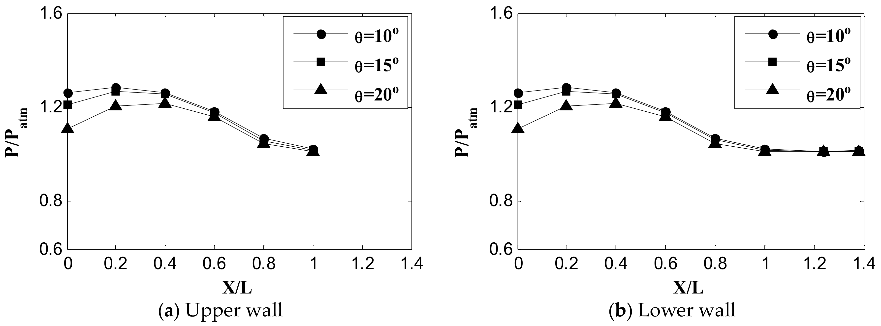
The variation in static pressure along the upper and lower nozzle walls at different mixer cone angles is shown in Figure 7. As shown by the figure, the pressure gradually decreased with the decreasing nozzle area. The pressure decreased with the increasing mixer cone angle because increasing the cone angle led to a greater expansion of flow inside the nozzle, which resulted in decreasing the pressure near the nozzle walls. The pressure along the upper and lower walls was almost identical due to the symmetry of the nozzle. Increasing the mixer cone angle reduced the pressure along the upper and lower walls.
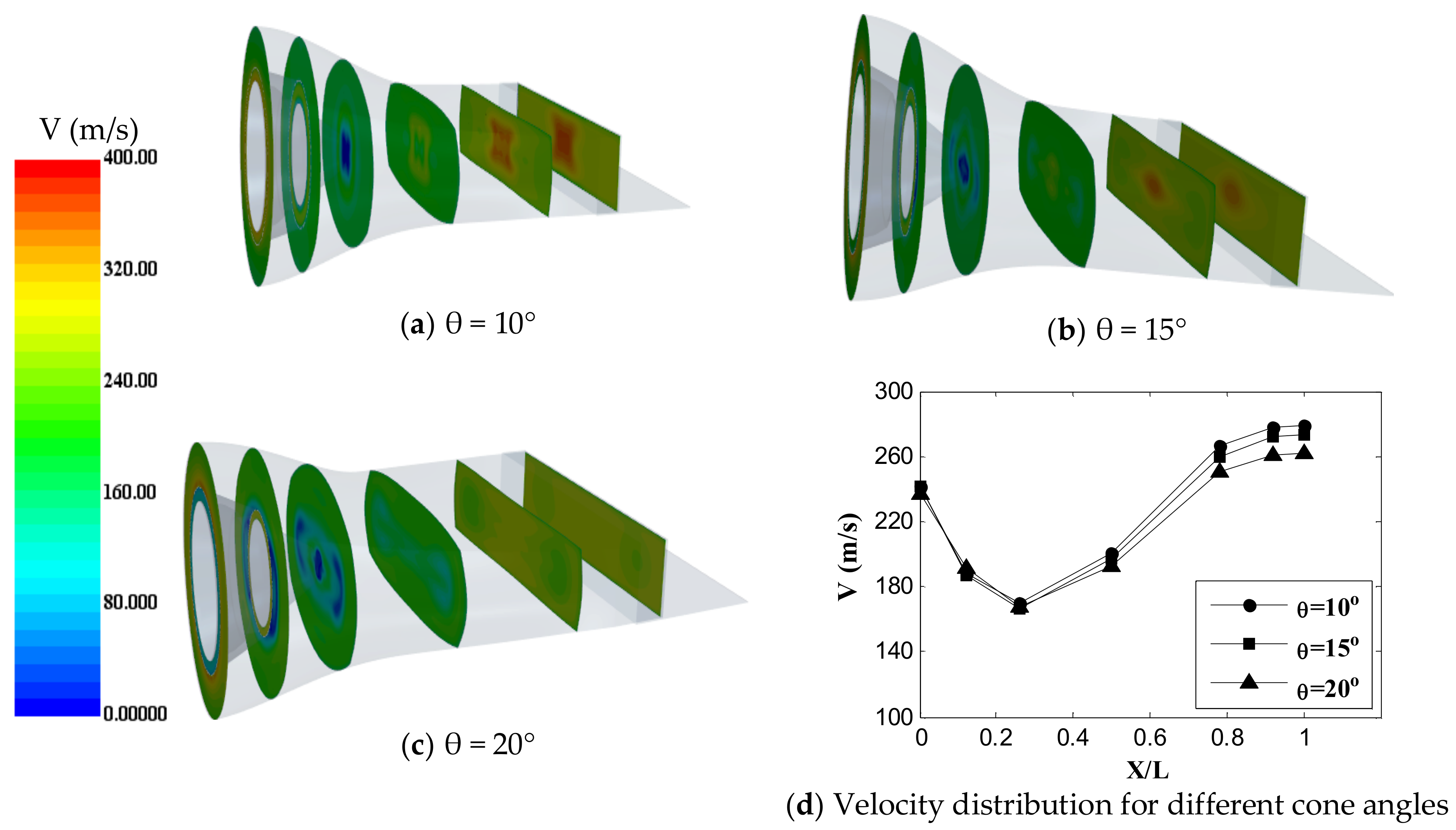
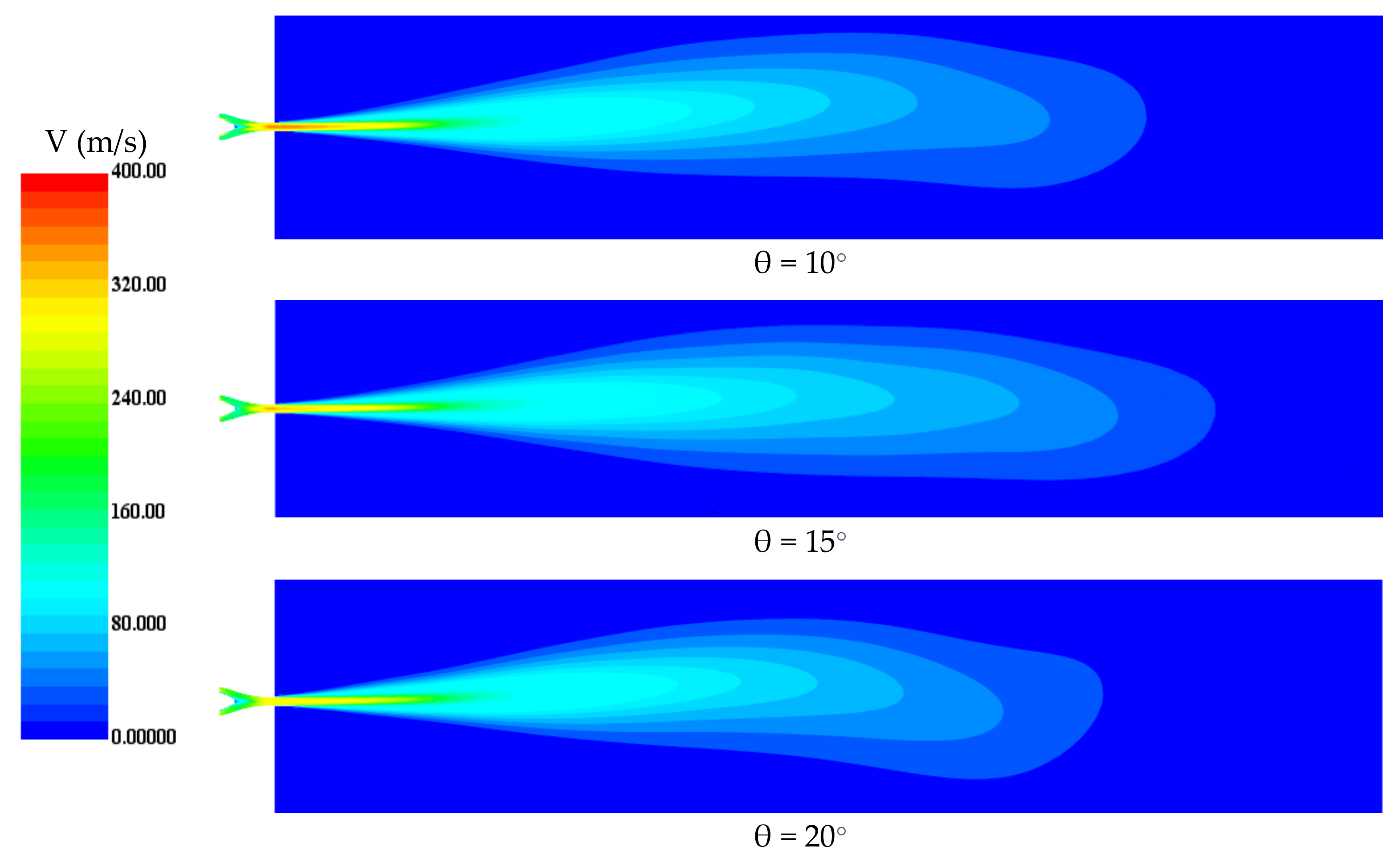
Figure 8 indicates the velocity contour and distribution at different locations inside the nozzle at different mixer cone angles. The figure indicated that the velocity decreased from the nozzle inlet until the end of the cone at X/L of 0.26, then the velocity gradually increased up to the nozzle exit as the area of the nozzle decreased. The velocity contours show the exiting of the core region at the center of the nozzle with the highest velocity. The size and velocity of the core region decreased with the increasing mixer cone angle. Figure 8d shows the average velocity distribution at different locations along the nozzle length. The figure demonstrates that increasing the mixer cone angle decreased the velocity inside the nozzle. This may be due to the flow separation point moving upstream. Additionally, as indicated by the velocity contour, the size of the core region with the highest velocity decreased with the increasing mixer cone angle due to the reduction in the core flow rate, as given in Table 3. This indicated that the velocity inside the nozzle strongly depended on the core flow rates and hence the mixer cone angle despite the constant area of the nozzle.
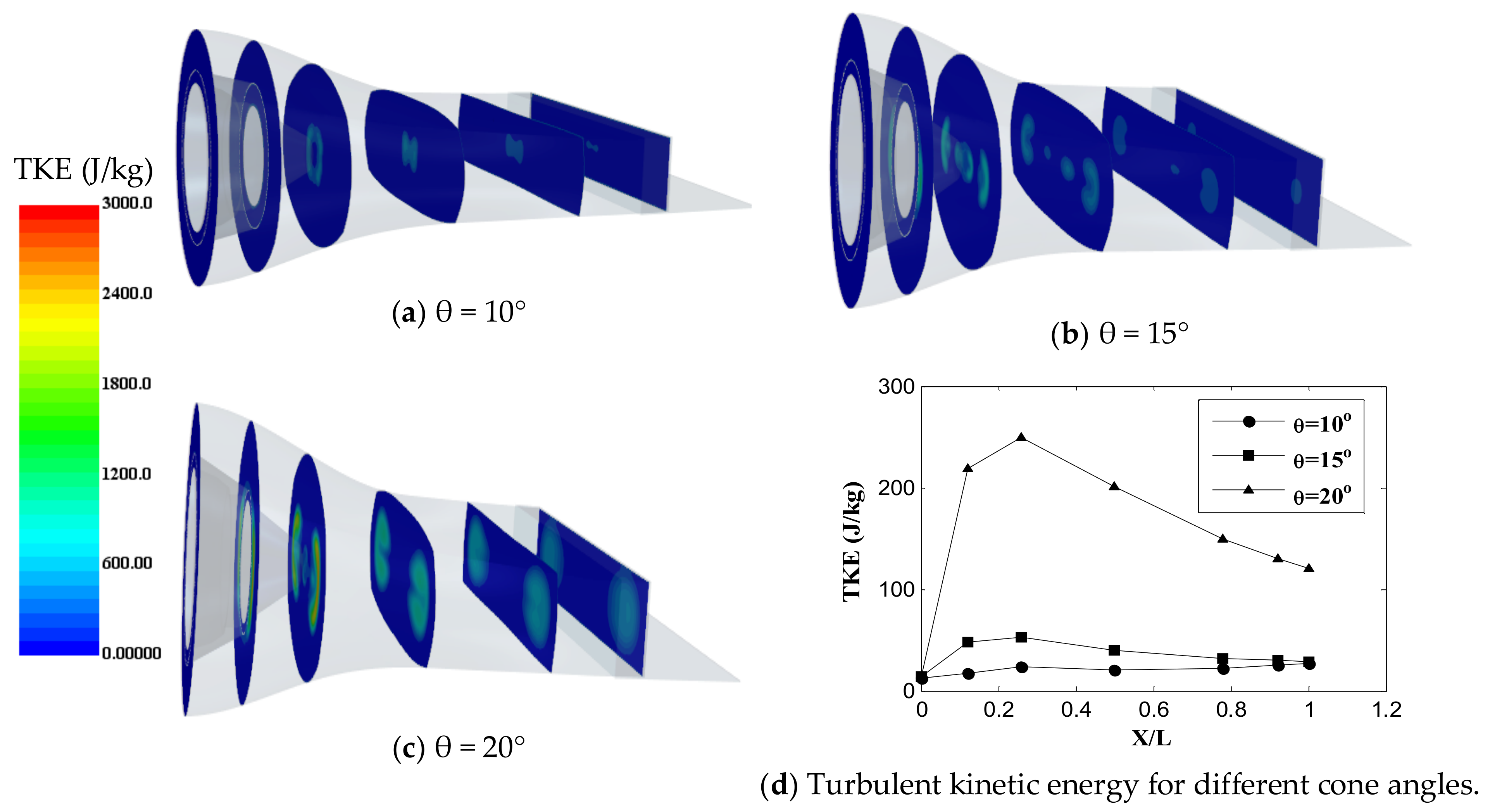
The turbulent kinetic energy (TKE) contours and distribution are shown in Figure 9. TKE is the most important parameter in the fluid flow because it is a measure of turbulence intensity and is directly related to momentum and heat. TKE can be used as an indication of mixing intensity. TKE was the highest at the end of the mixer cone, where the mixing between the lower-temperature bypass flow and higher-temperature core flow occurs. Figure 9d indicates the average values of TKE at different locations along the nozzle length. The figure indicates that the TKE was the highest at the largest mixer cone angle, demonstrating that increasing the mixer cone angle increased the turbulence motion inside the nozzle and hence improved the mixing process between the hot and cold streams, which resulted in decreasing the temperature.
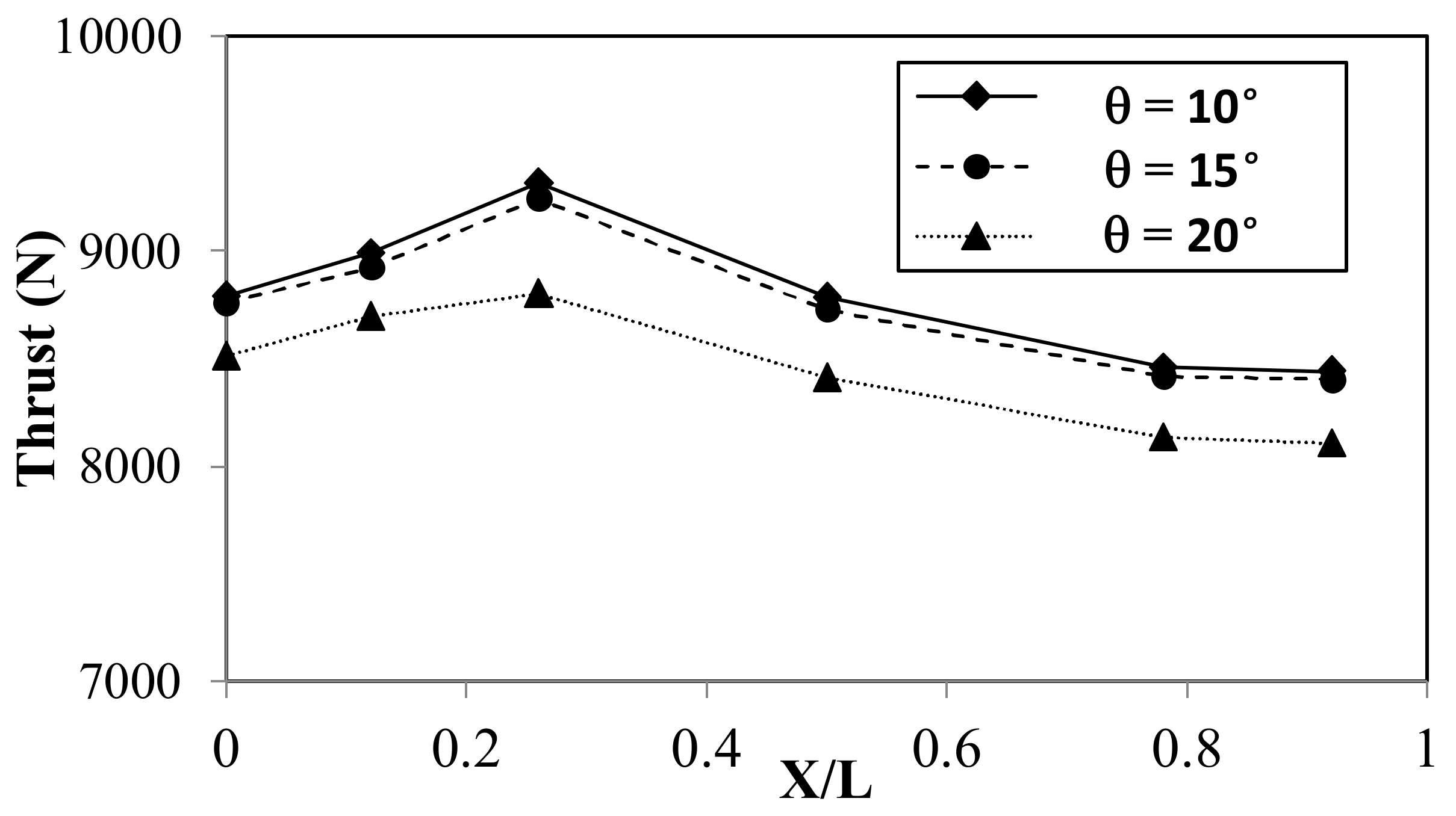
Figure 10 indicates the distribution of thrust force at different locations for different cone angles. The thrust force proportion with the nozzle area increased gradually up to the mixer end as the nozzle area increased, then gradually decreased and became nearly constant near the nozzle exit, where the area was almost the same. The thrust force accelerates the flow inside the nozzle by decreasing the pressure and increasing the velocity so that the velocity gradually increases after the mixer ends up at the nozzle exit, as shown in Figure 8. The figure shows that the thrust decreased with the increasing cone angle. As the cone angle increased, the area available for flow decreased, resulting in a reduction in the flow rate and hence decreasing the thrust.
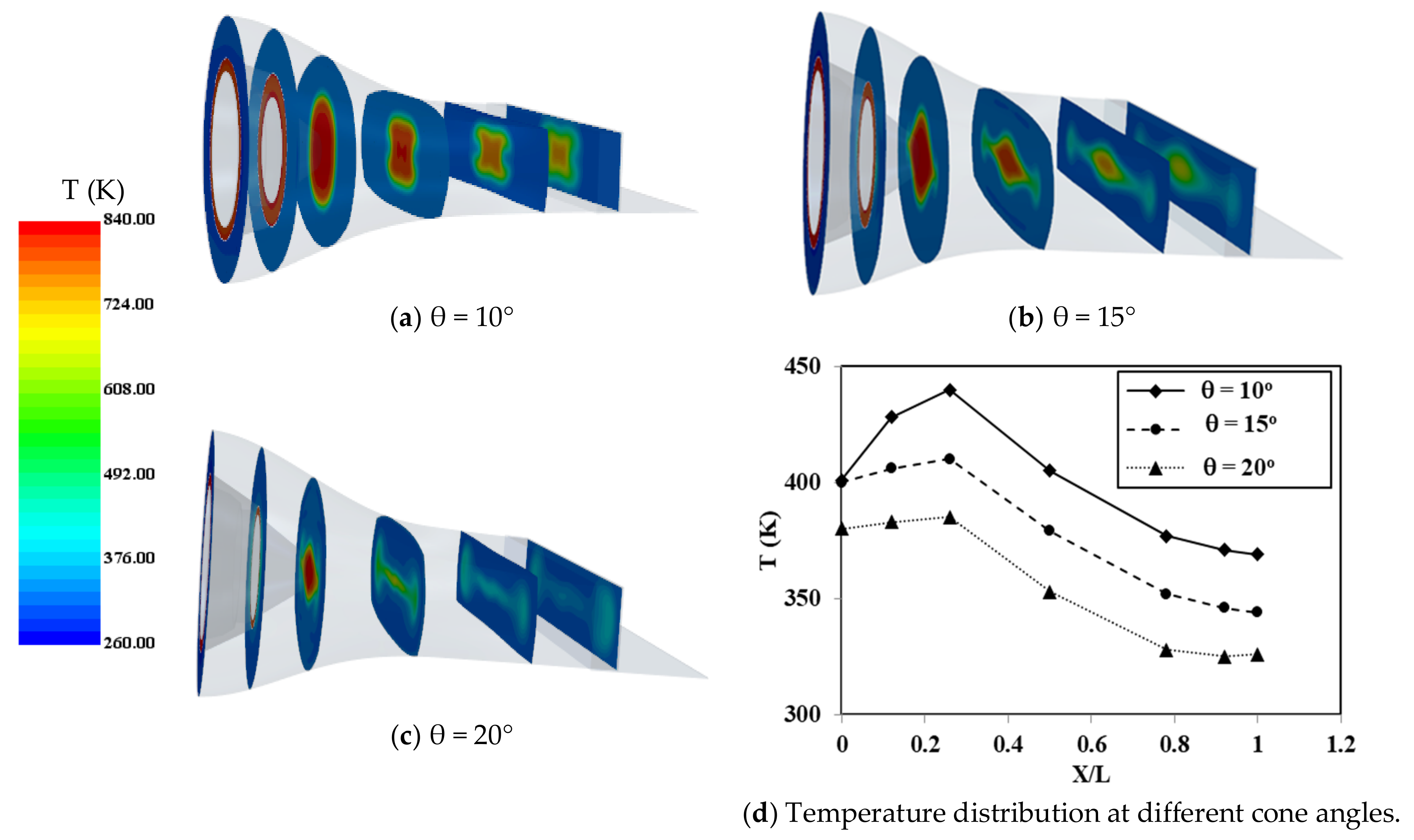
The distribution and temperature contours at different sections along the length of the nozzle for different cone angles of the mixer are illustrated in Figure 11. As shown by the temperature contours, there was a core flow region with high temperature surrounded and separated by a bypass flow with low temperature. As indicated by the figure, the temperature of the core region at the center of the nozzle decreased with the increasing mixer cone angle due to the reduction in the core flow rate. The average temperature of the selected sections, as shown in Figure 11d, decreased gradually from the end of the tail cone up to the nozzle exit because the nozzle geometry shields the temperature. The reduction in the temperature results from increasing the mixer cone angle, which is due to the reduction in a high-temperature core flow and increasing bypass cold flow, as indicated in Table 3. Additionally, improving the mixing process due to increasing the turbulence motion, as illustrated by TKE in Figure 9, was another reason.
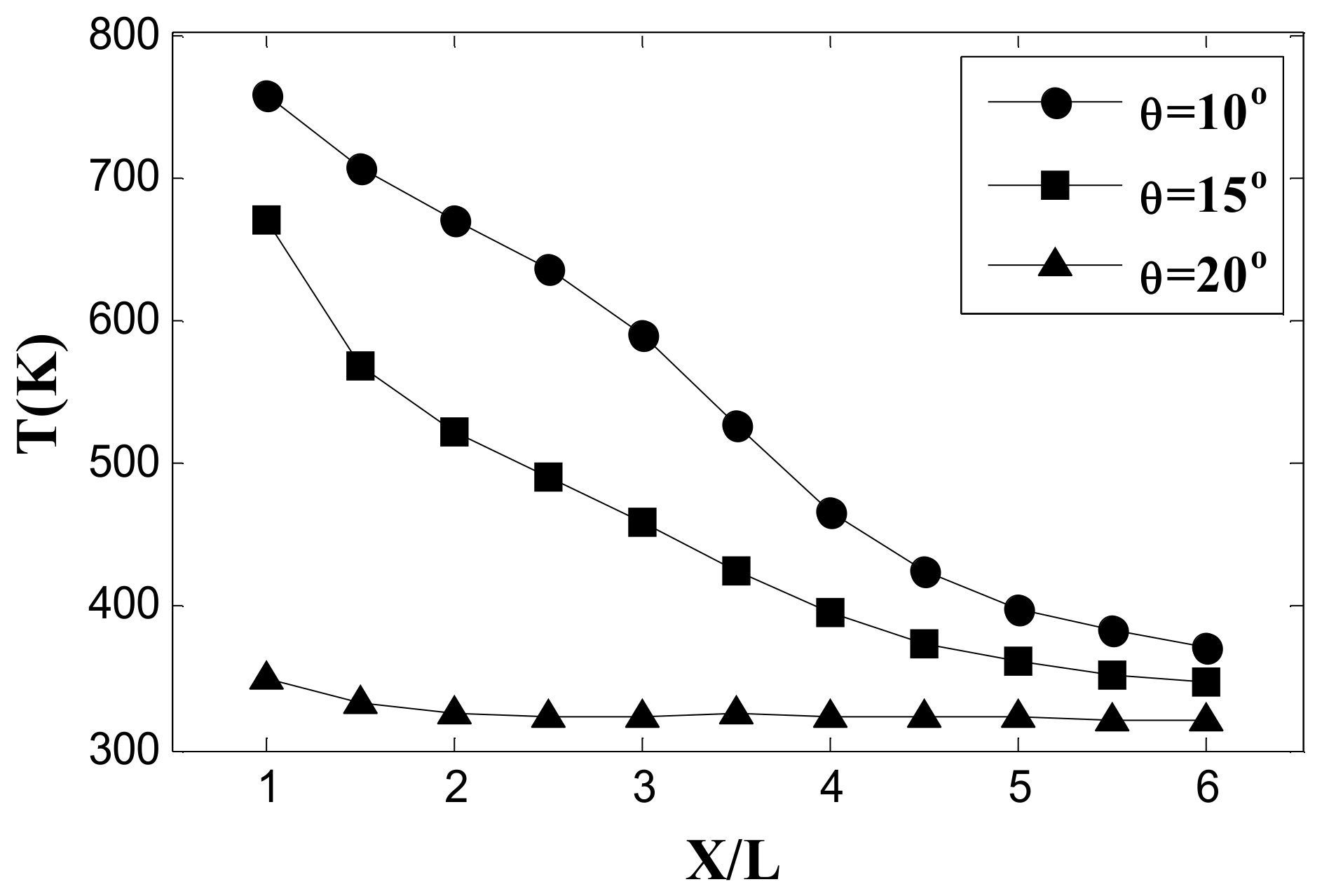
The exhausted jet, which is indicated by velocity contour and radial velocity distribution at different axial locations along the jet length at different mixer cone angles, is shown in 
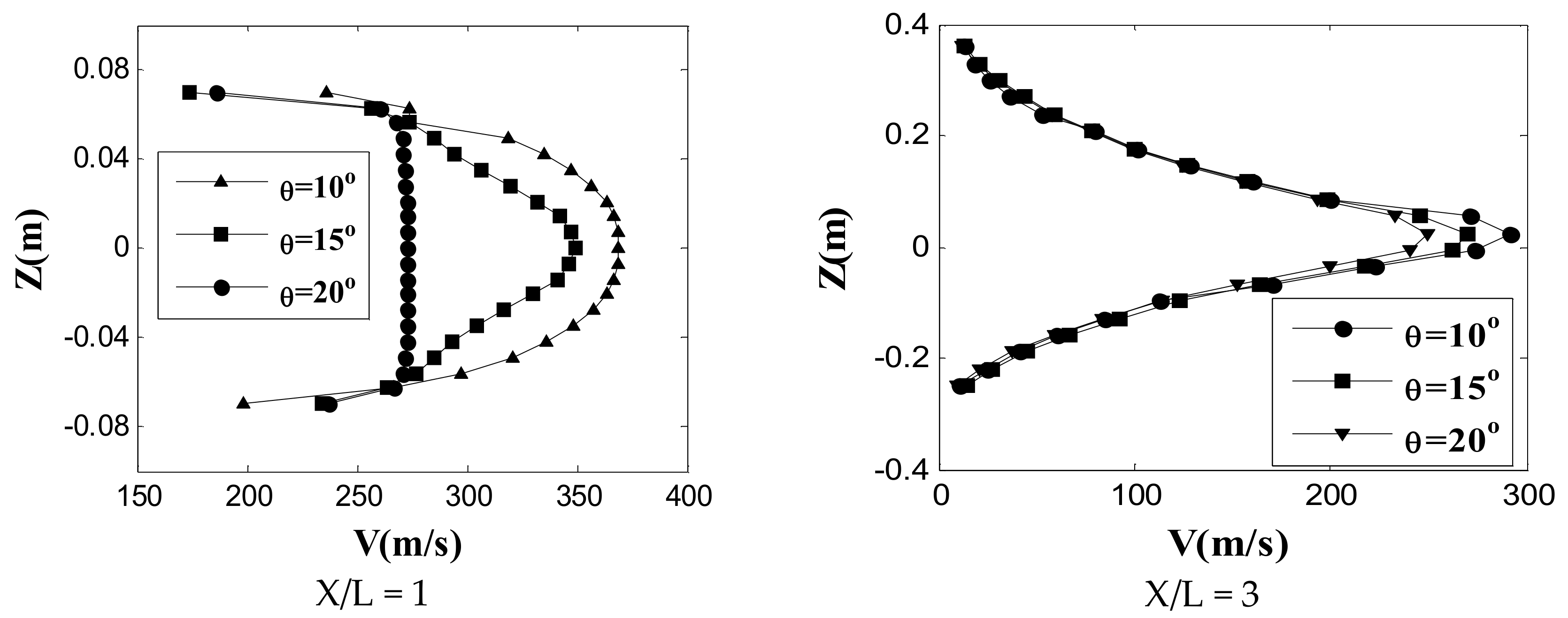
Figure 12. As indicated by the velocity contour, the external jet is characterized by the highest velocity region at its centerline, which is called a potential core region. The potential core is known as a region in the jet where the centerline velocity is uniform and equal to the exit centerline velocity, as indicated by the velocity distribution. The jet’s initial regime is known as the region of the establishment of flow and extends from the exit of the nozzle until the potential core apex. The other region is known as the region of stabled flow, which starts at the potential core end and is characterized by the gradual reduction in the centerline velocity. The velocity distribution illustrated in Figure 13 shows that the velocity increased at the nozzle exit, where the mixing between the ambient air and exhausting hot gases was weak. With increasing the distance from the nozzle exit, the surrounding air was entrained into the exhausted jet and resulting in an increase in the jet size in the axial direction and a reduction in the centerline velocity. The figure also indicated that the higher mixer cone angle had the lowest velocity at the nozzle exit at X/L = 1. This demonstrated that increasing the mixer cone angle could decrease the noise generated by the engine nozzle by decreasing the peak velocity at the nozzle exit.
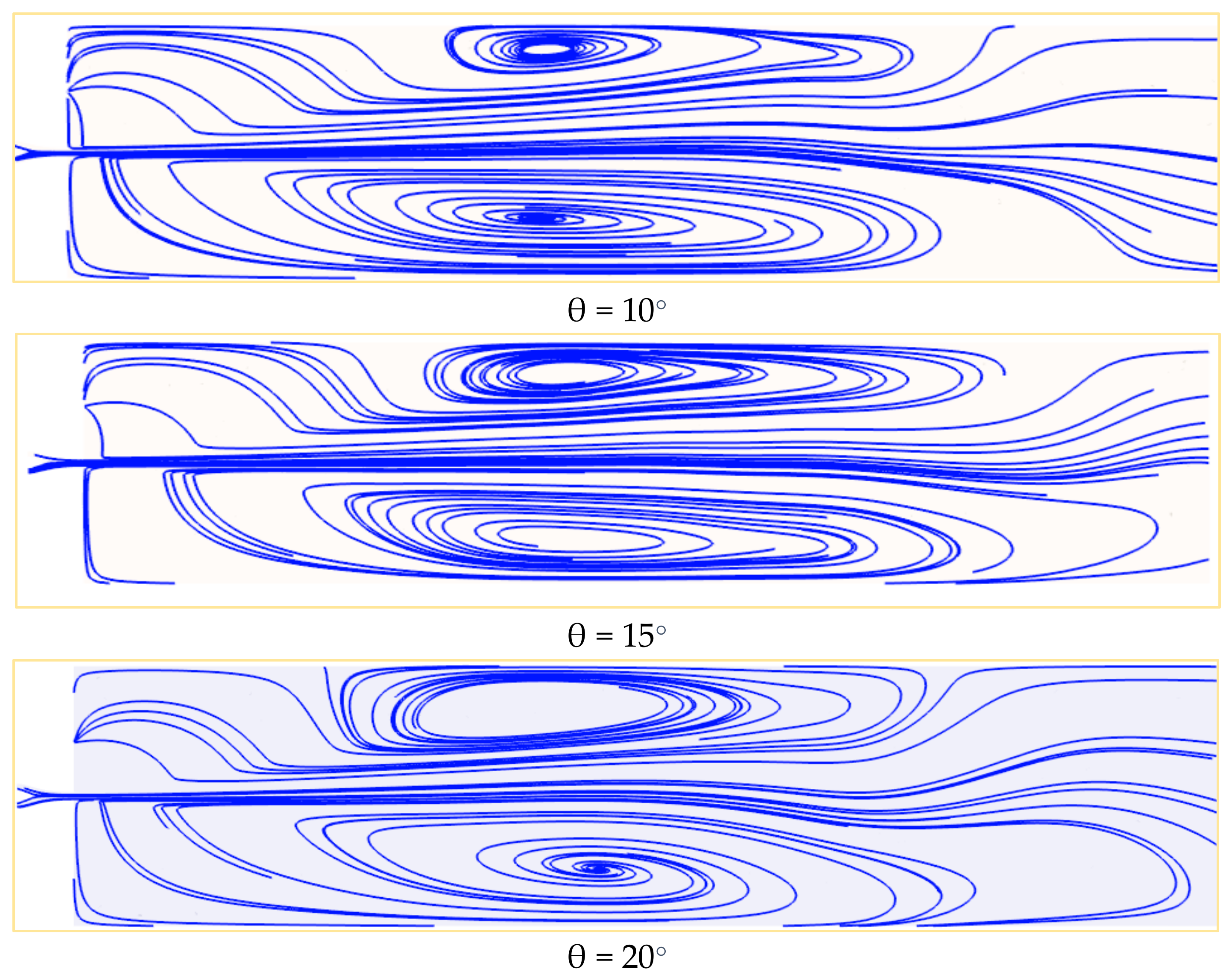
Figure 14 indicates constrained streamlines at the vertical plane along with the computational domain for different mixer cone angles. As indicated by the figure, large-scale vortices are formed on the jet boundary so that vortices can entrain the surrounding air into the exhausted jet. The entrained ambient air with low momentum tries to gain momentum from the high-velocity exhausted jet that prevails in the centerline of the exhausted jet. This results in the transfer of entertain air into the jet centerline, leading to a reduction in the velocity and temperature at this region.
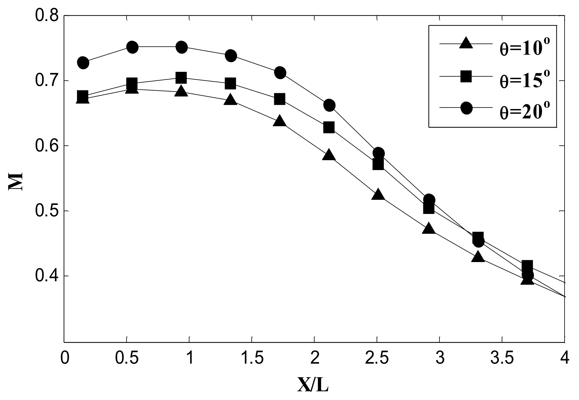
The M distribution at the centerline of the exhausted jet for different mixer cone angles is shown in Figure 15. As shown by the figure, M increased from the nozzle exit up to X/L = 1.3, indicating the extension of the core region in the axial direction. After the core region, there was a steep reduction in M along the centerline of the jet. At the core region, the mixing was the lowest and resulted in increasing M, and with increasing the distance from the nozzle exit, the mixing process increased until reaching the jet centerline, which resulted in increasing the spread of the jet and vanishing the core region leading to a further decrease in M. The M distribution at the jet centerline decreased with the increasing mixer cone angle, indicating the improvement of the mixing process between the exhausted jet and entrained ambient air. The velocity contour and M distribution show that the length of the core region is almost the same for different mixer angles.
Figure 16 illustrates the temperature distribution along the centerline of the exhausted jet at different angles. The temperature increased near the nozzle exit along the potential core region, and then the temperature gradually reduced due to the spreading of the jet, thus improving the mixing between the exhausted gases and surrounding air. The figure indicated that the temperature distribution along the jet centerline decreased with the increasing mixer cone angle. As shown by the temperature contour in Figure 11, the size and temperature at the nozzle exit decreased with the increasing mixer cone angle, which resulted in the reduction of the centerline temperature. Moreover, as discussed in the previous sections, increasing the mixer cone angle improved the mixing between the hot gases and cold surrounding air, which resulted in reducing the temperature. The reduction in the temperature downstream of the nozzle exit reduced the infrared radiation.

4.2. Effect of Aft-Deck

In this section, the effect of the aft-deck on the nozzle performance was discussed. The nozzle performance with aft-deck was compared to that of the nozzle without aft-deck. Then, the effect of the aft-deck length and shape was studied. The internal flow at different sections of the serpentine nozzle without and with an aft-deck is shown in Figure 17. 
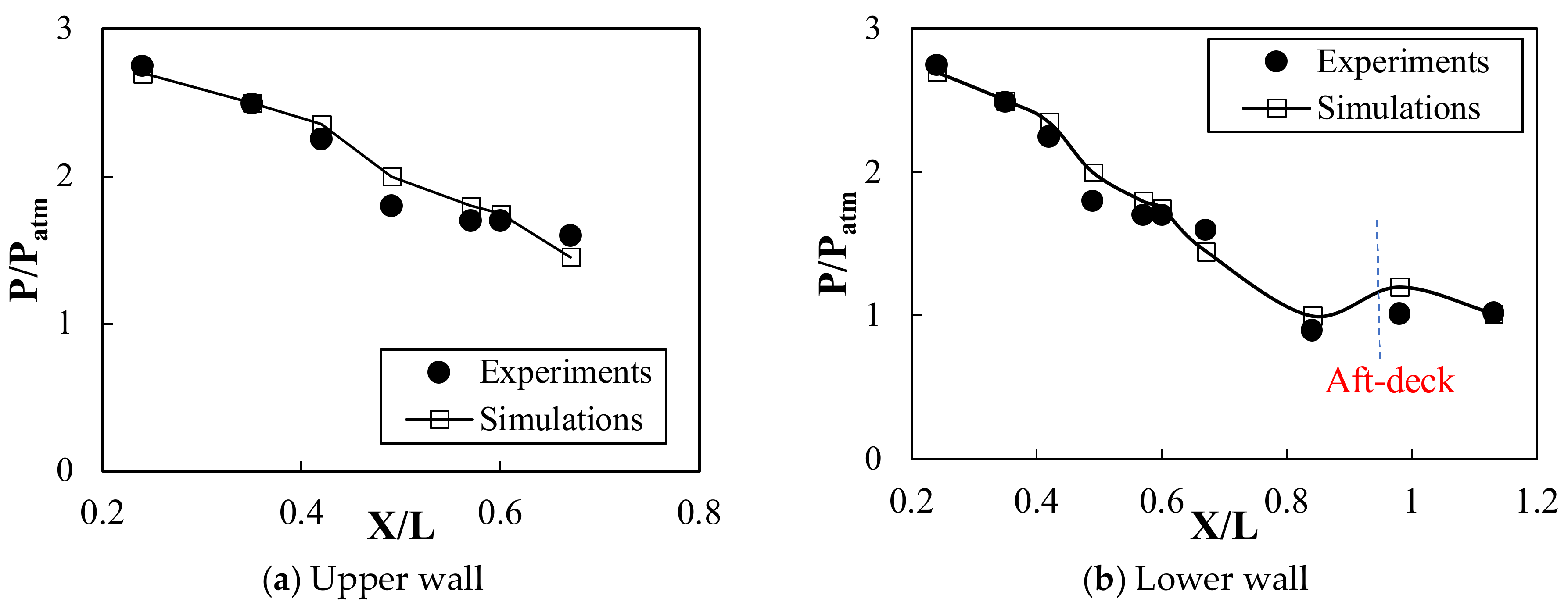
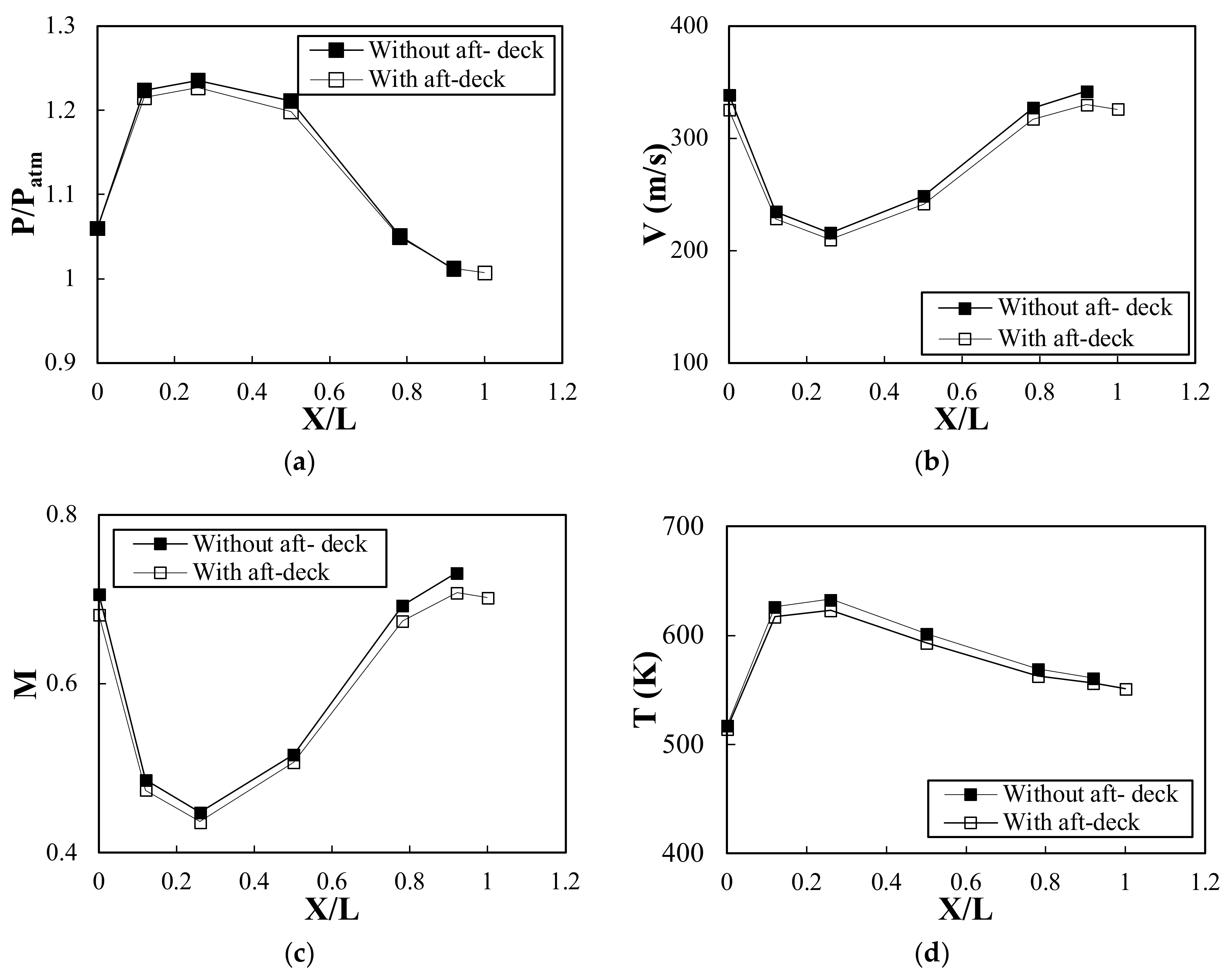
Figure 17a indicates the pressure distribution at different sections along the length of the nozzle. The pressure (P) was nondimensionalized with atmospheric pressure (Patm). For the two nozzles, the pressure increased gradually until X/L = 0.26 as the area increased, and then it decreased downstream until the distance of X/L = 0.78 as the area gradually decreased, and the flow expanded. The two nozzles have an almost constant area region from distance X/L = 0.78; in this region, the pressure was almost constant up to the nozzle exit. The nozzle without the aft-deck had an almost higher-pressure distribution than that of the nozzle with the aft-deck. As mentioned by Nageswara and Kushari [15], the presence of the aft-deck resulted in an additional nozzle length leading to an increase in the wetted surface and boundary layer thickness in this section, so the flow accelerated in the central part of the nozzle cross-sectional area to satisfy the mass conservation that resulted in a greater expansion of flow inside the nozzle and hence decreased the pressure inside the nozzle.
Figure 17b indicates the velocity magnitude at different locations inside the nozzle without and with an aft-deck. As shown by the figures, the velocity decreased gradually from the nozzle inlet until the distance of X/L = 0.26 and then increased gradually up to the nozzle exit exhibiting the opposite trend of pressure. As it is known, the area variation of the nozzle area along its length resulted in converting pressure energy into kinetic energy. The figure illustrated that the velocity of the nozzle with aft-deck was lower than that of the nozzle without the aft-deck. The lower velocity of the nozzle with an aft-deck may be attributed to the viscous interaction between the aft- deck and the jet, which decreased the velocity.
The distribution of Ma at various locations along the nozzle length without and with an aft-deck is shown in Figure 17c. As shown by the figure, the Ma of the nozzle with an aft-deck is lower than that of the nozzle without an aft-deck. The aft-deck at the exit of the nozzle restricted the entrainment of the surrounding fluid at the aft-deck side. This resulted in reducing the momentum gains from the fluid with a high momentum surrounding the jet axis, leading to a reduction in the spreading of the jet.
Figure 17d illustrates the distribution of the temperature at different locations along the length of the nozzle without and with an aft-deck. The temperature decreased gradually after a distance of X/L = 0.26, where the annular mixer intensified the mixing process between cold air from bypass and core hot gases, and resulted in a reduction in temperature. The temperature inside the nozzle with the aft-deck was almost lower than that of the nozzle without an aft-deck. As mentioned in the above sections, the presence of the aft-deck increases the flow expansion inside the nozzle and enhances the mixing process between the bypass cold air and core hot gases leading to a decrease in the temperature inside the nozzle.
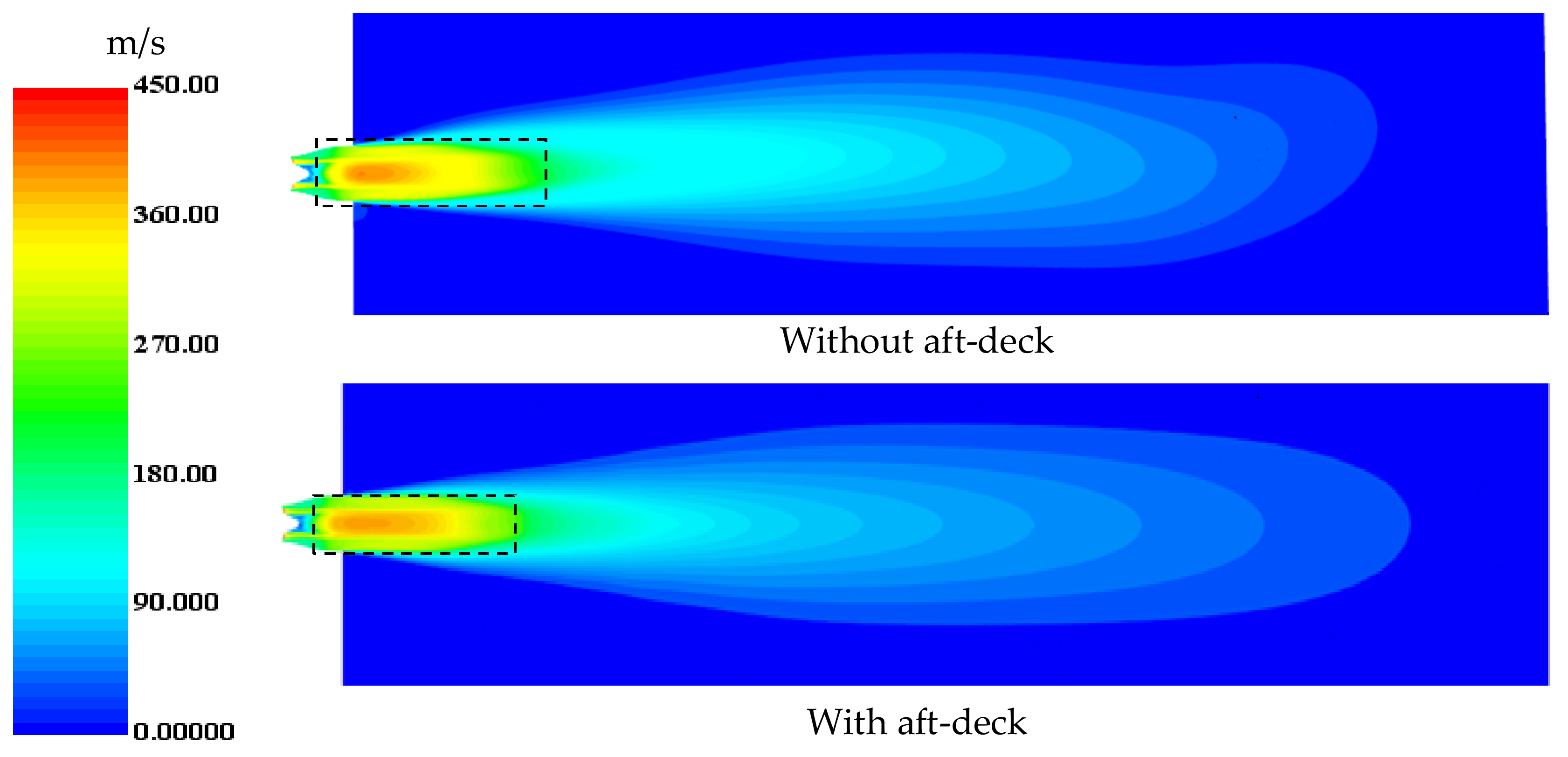
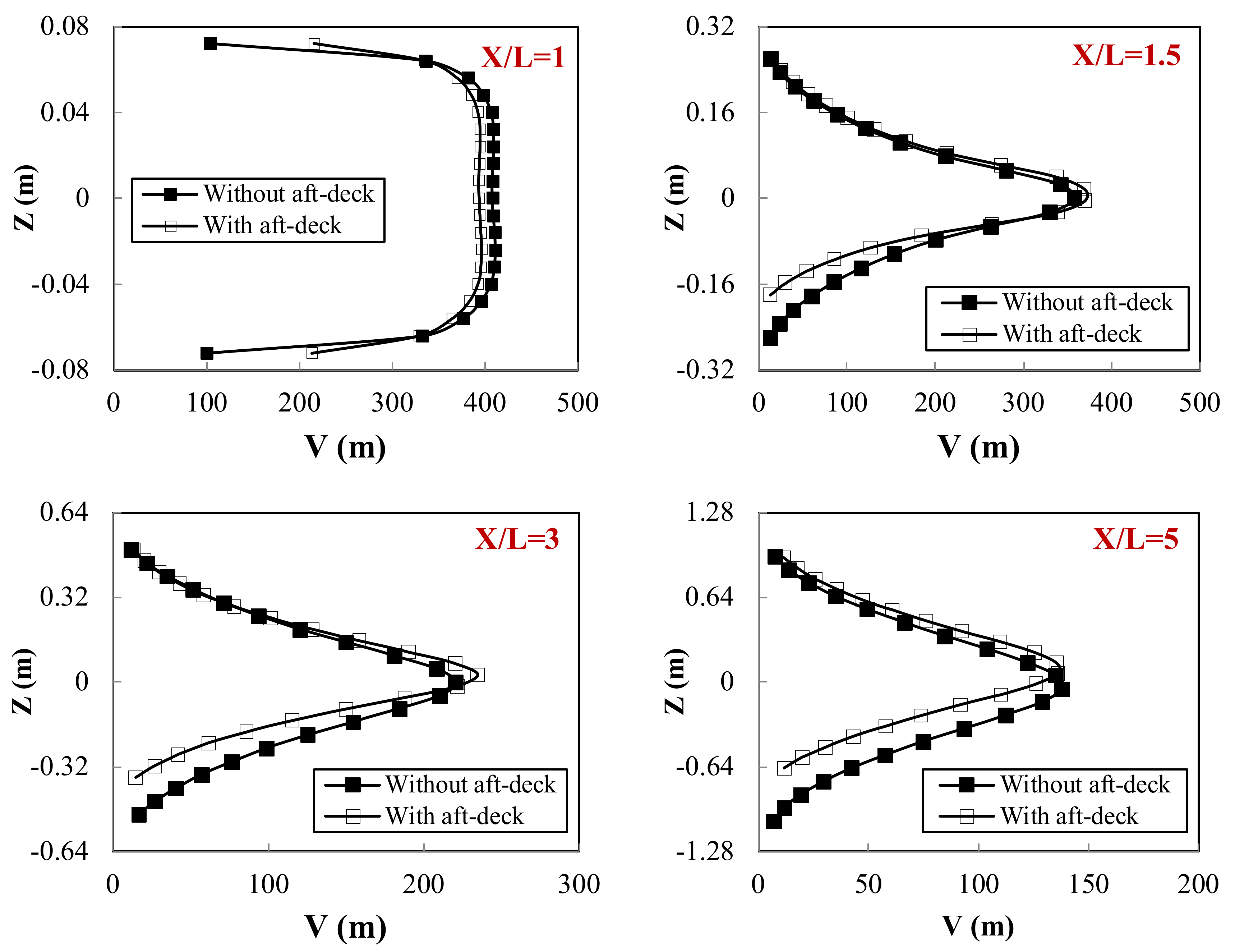
The velocity contour at the horizontal plane and radial velocity profiles along the jet length of the nozzle with and without an aft-deck is shown in Figure 18 and Figure 19, respectively. As shown in the figure, at the exit of the nozzle (X/L = 1), the jet velocity was uniform and at the highest level, with a nearly top-hat profile because the mixing process between the jet and ambient air was weak. A thin shear layer was created at the exit of the nozzle because of the large velocity difference between the jet and ambient air, and this shear layer continuously grew downstream. With the increase in the shear layer, the entrainment of the ambient air into the jet increased, increasing the mixing process. As a consequence, the jet spreads outward in a radial direction, and the velocity of the jet gradually decreases downstream. The region at the nozzle exit along the central portion of the jet with an almost uniform mean velocity refers to the potential core region (represented as a dotted box). The potential core eventually disappears due to the spreading of the jet and the shear layer. Beyond the potential core region, the velocity profiles convert to a bell-shaped profile at an axial distance (X/L) from three to five. The aft-deck increased the length of the nozzle; hence, the wetted perimeter area at the exit of the nozzle increased, which resulted in a reduction of the size and length of the potential core of the jet, which is considered the highest temperature region, as illustrated by the velocity contour shown in Figure 18 that can reduce the infrared radiation. On the other hand, the reduction in the velocity at the nozzle exit can reduce the noise produced by the nozzle.
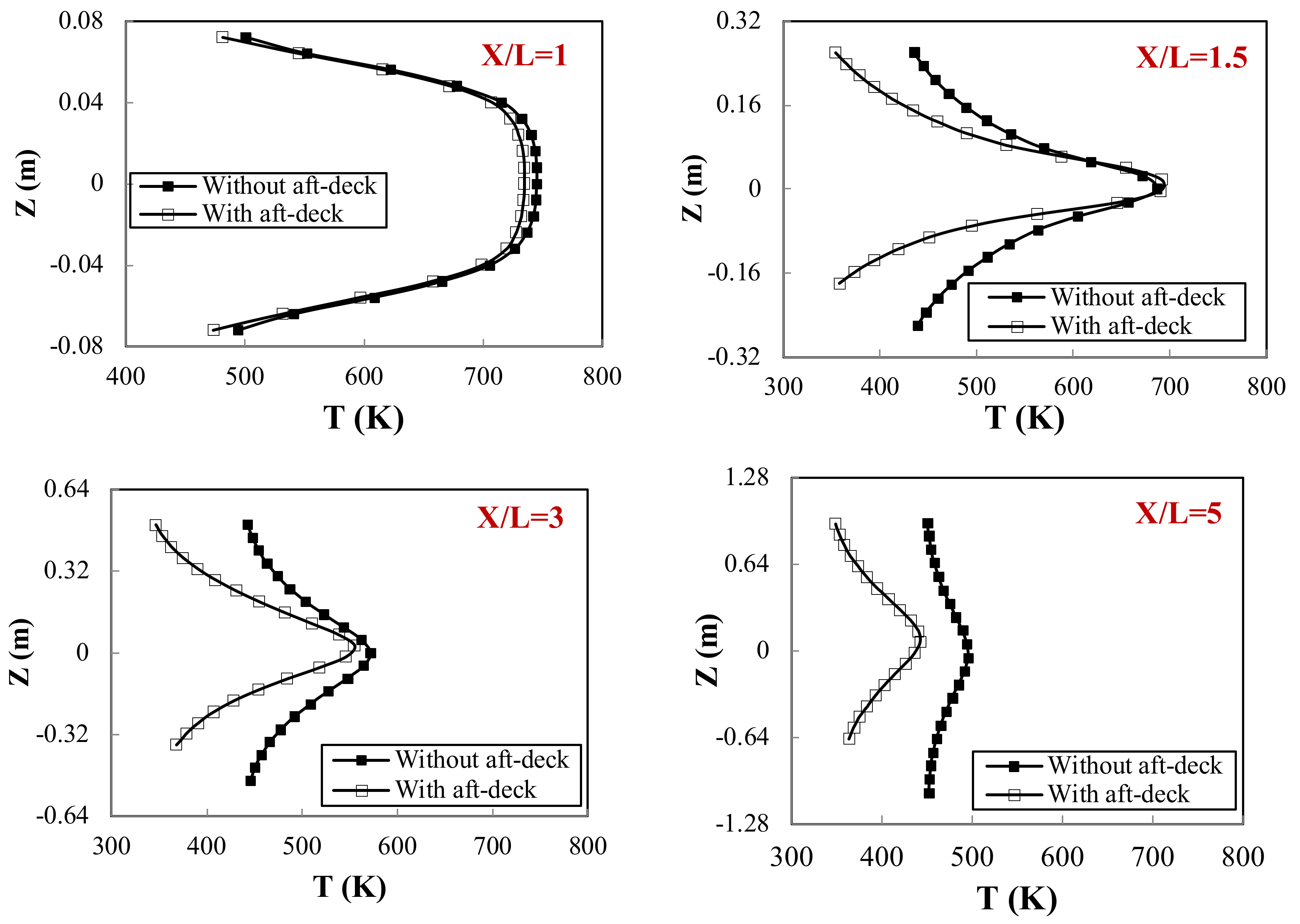
Figure 20 illustrates the temperature profiles at different locations (X/L) of 1, 1.5, 3, and 5 along the jet length for the nozzle with and without an aft-deck. As indicated by the figure, the temperature was the highest at the nozzle exit where the highest temperature core region is exited. With the increasing distance from the nozzle exit, the temperature decreased as the mixing between the exhausted gases and ambient air increased, and the exhausted jet expanded more. Furthermore, the figure demonstrated that the presence of the aft-deck decreased the temperature of the exhausted gas. As discussed in the above sections, the aft-deck reduced the length and size of the potential core with the highest temperature. Additionally, the aft-deck increased the wetted area at the nozzle exit, which improved the mixing process between exhausted gases and ambient air and increased the expansion of the exhausted gases, which resulted in a decreasing temperature.
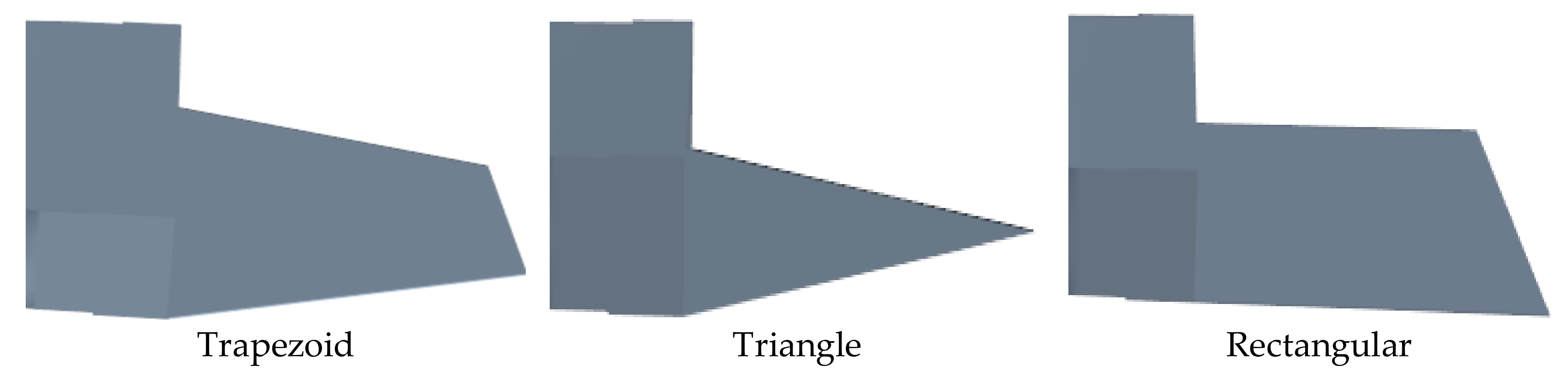
This section investigated the effect of the aft-deck length and shape on the flow characteristics. Three aft-deck lengths of 140, 280, and 420 mm and three different models of aft-deck with trapezoid, triangle, and rectangular shapes, as shown in Figure 21, were investigated. The length of all shapes was kept at the largest length of 420 mm.
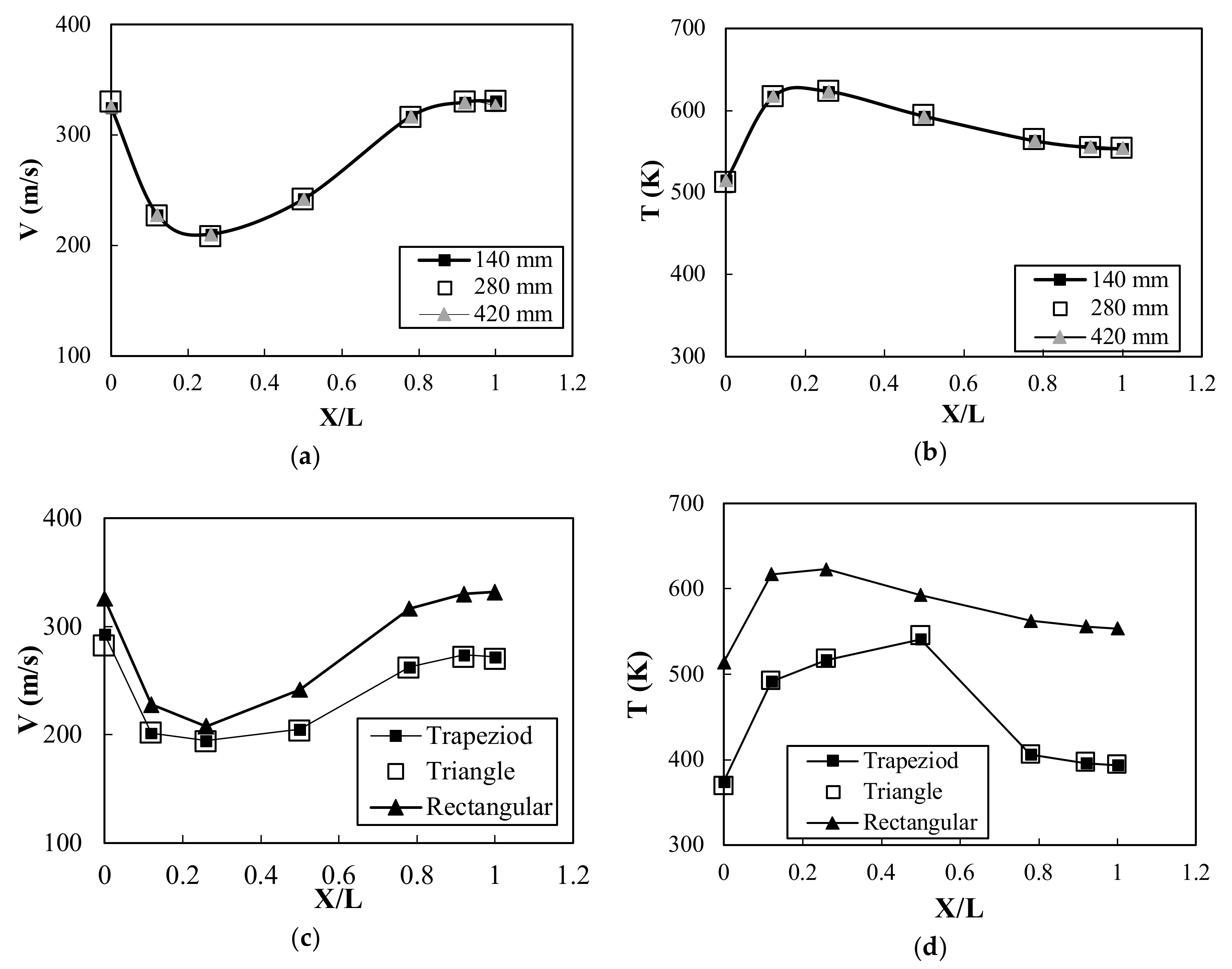
Figure 22 indicates the average velocity magnitude and temperature distributions at different locations along the nozzle length for different lengths and shapes of the aft-deck. As shown in Figure 22a,b, the aft-deck had no effect on the velocity and temperature distributions inside the nozzle. Although increasing the aft-deck length increased the length of the nozzle and wetted area at the exit, this had no effect on the internal flow. On another hand, as indicated by 
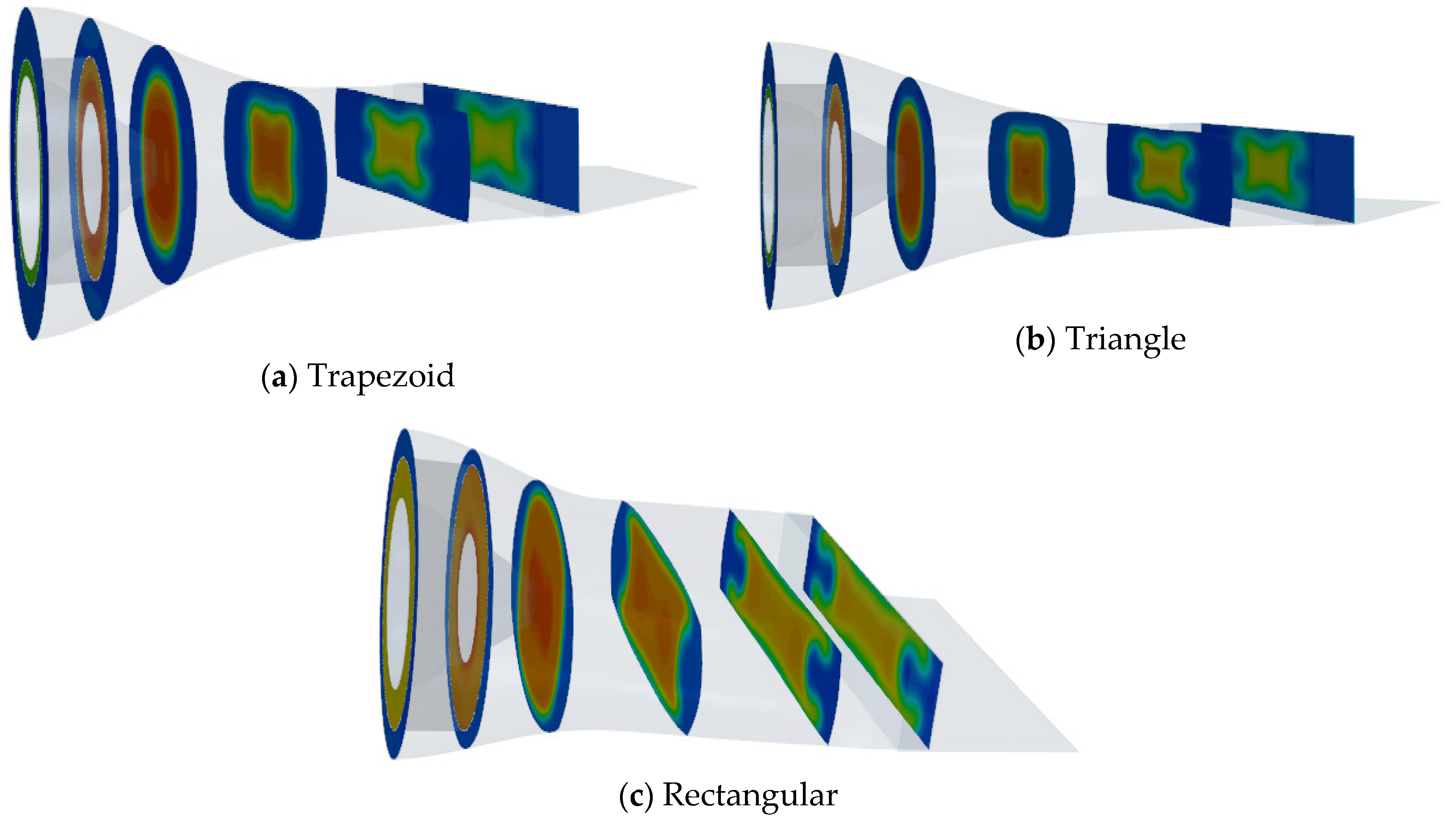
Figure 22c,d, the velocity and temperature inside the nozzles with a trapezoid and triangle aft-deck was the same, and it was high for the nozzle with a rectangular aft- deck. This demonstrated that the aft-deck with a rectangular shape can increase the expansion of flow inside the nozzle, which resulted in decreasing the pressure and, hence, increasing the velocity. The increase in temperature for the nozzle with a rectangular aft-deck can be explained using the temperature contours indicated by Figure 23a–c. As illustrated by the figure, the size and temperature of the hottest core region for the nozzle with a trapezoid and triangle aft-deck were smaller than that of the nozzle with a rectangular aft-deck. Therefore, the average temperature at each location, indicated by the temperature contour for the triangle and trapezoid aft-deck shapes, was lower than that of a rectangular aft-deck. It can be concluded that the aft-deck with trapezoid and triangle shapes had the same effect on the internal flow characteristics. The trapezoid and triangle aft-deck shapes could increase the flow expansion inside the nozzle, which can reduce the velocity, and the noise generated by the nozzle, as well as decrease the wall temperature by decreasing the high-temperature core flow, which results in decreased infrared radiation. The figure demonstrated that the length of the aft-deck had no effect on the internal flow characteristics, but its shape could affect it.
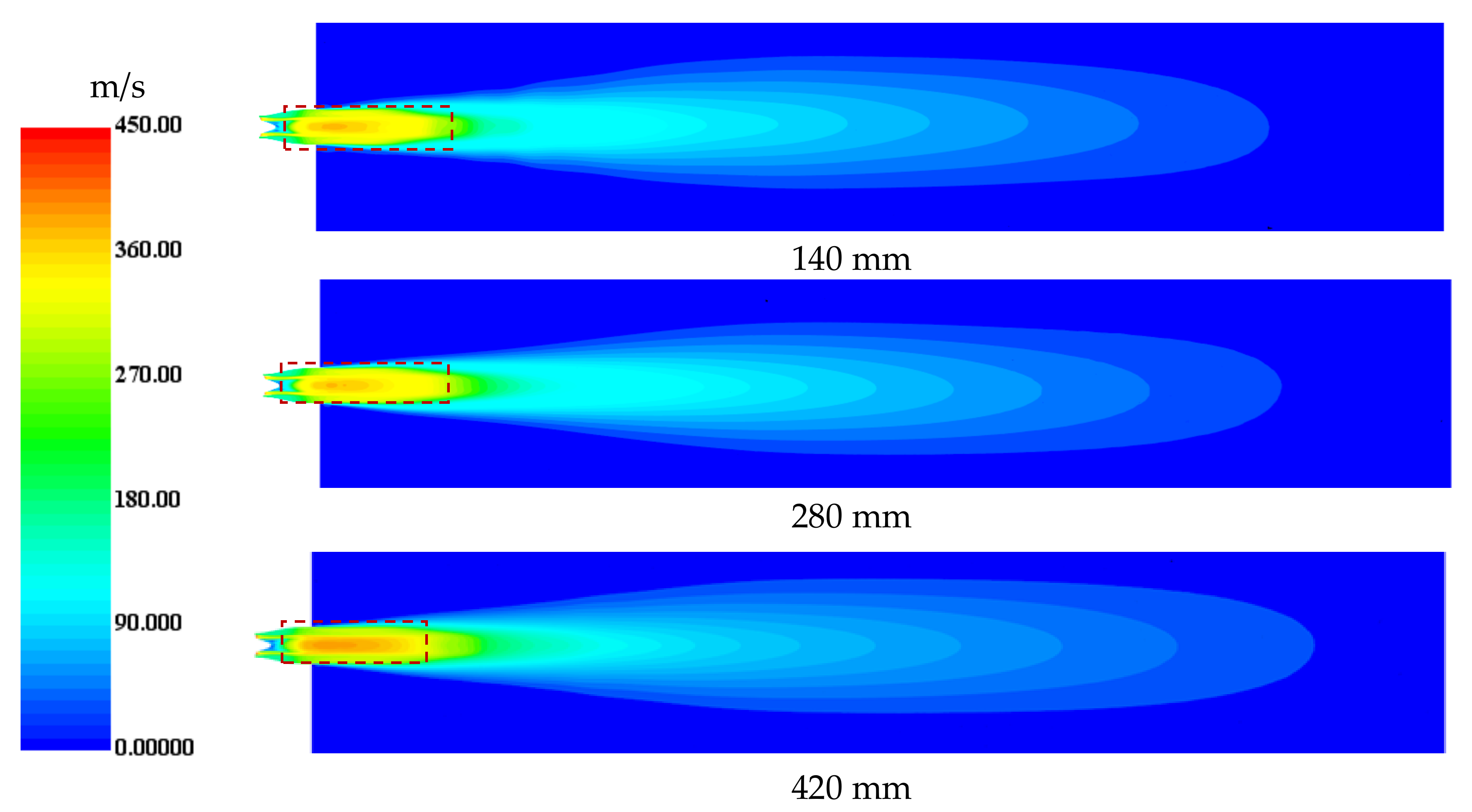
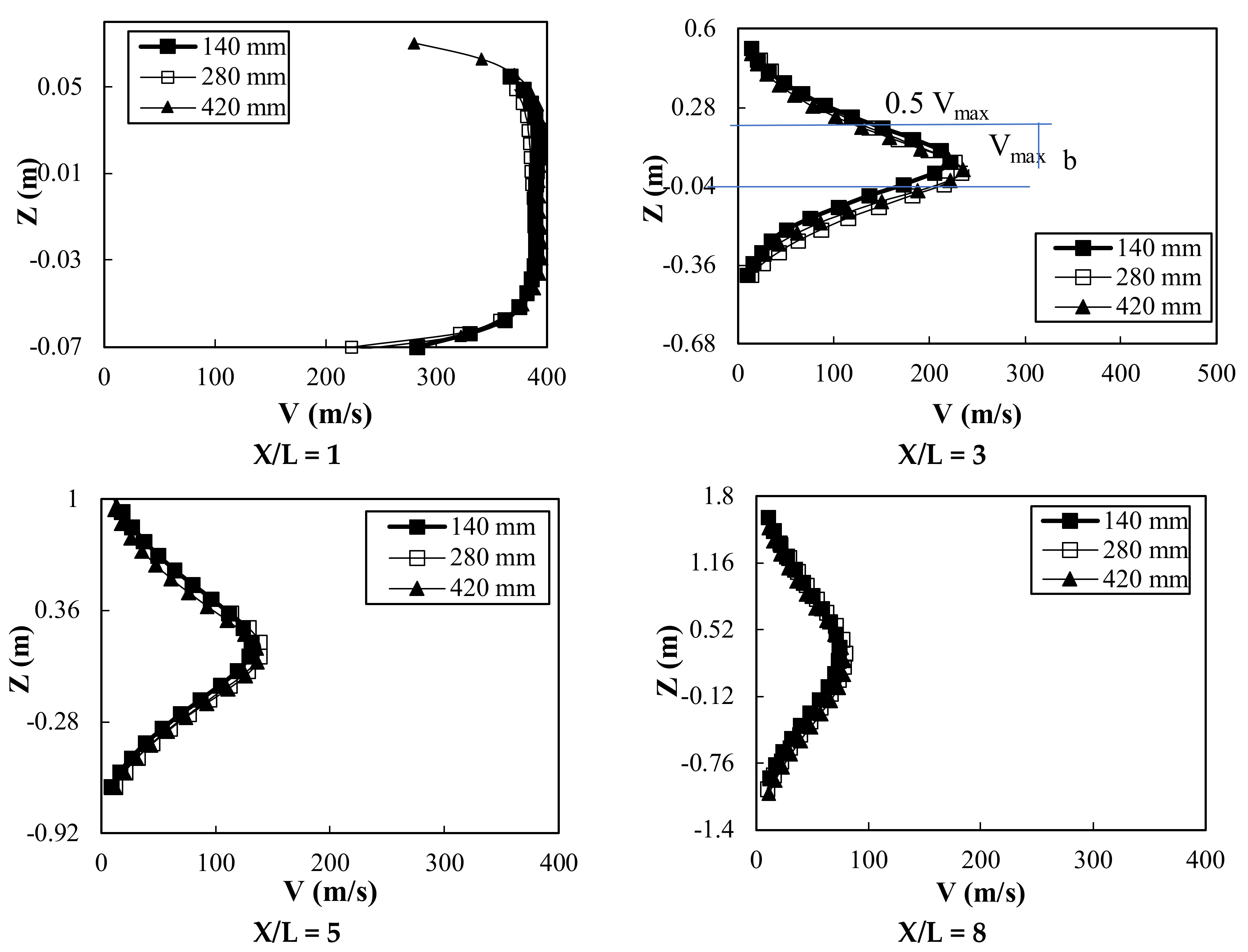
Figure 24 and Figure 25 illustrate the velocity contour in the horizontal plane and the radial distribution of velocity at different aft-deck lengths. The two figures demonstrate that an aft-deck had no obvious effect on the jet velocity. However, the velocity contours shown in 
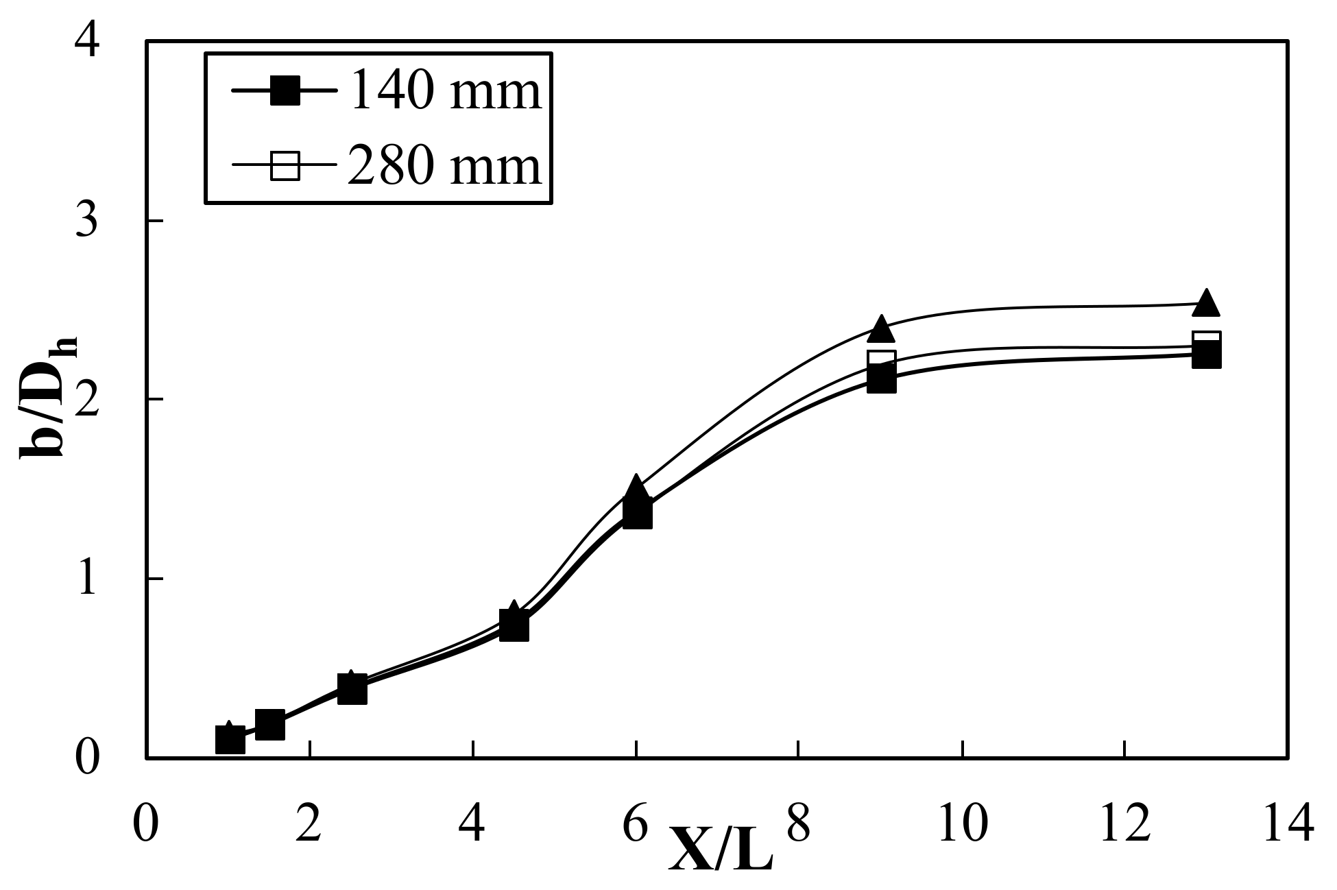
Figure 24 indicate that an aft-deck can increase the spreading of the jet. This can be explained by using a new parameter that can characterize the external jet called the half jet width. The velocity distribution shown in Figure 22 indicated that the maximum mean velocity was located at the jet centerline. The distance from the jet centerline to that at which the velocity is equal to a half maximum velocity is known as the width of the half-jet (b), and this characterizes the jet growth. The jet half-width (b) normalized by the nozzle exit hydraulic diameter (Dh) at different axial lengths for different aft-deck lengths is shown in Figure 26. As indicated by the figure, increasing the axial distance from the exit of the nozzle increased the jet’s half-width because the jet gradually spread. Figure 24 and Figure 26 demonstrate that increasing the aft-deck length increased the half-jet width, which resulted in the increased spreading of the jet.
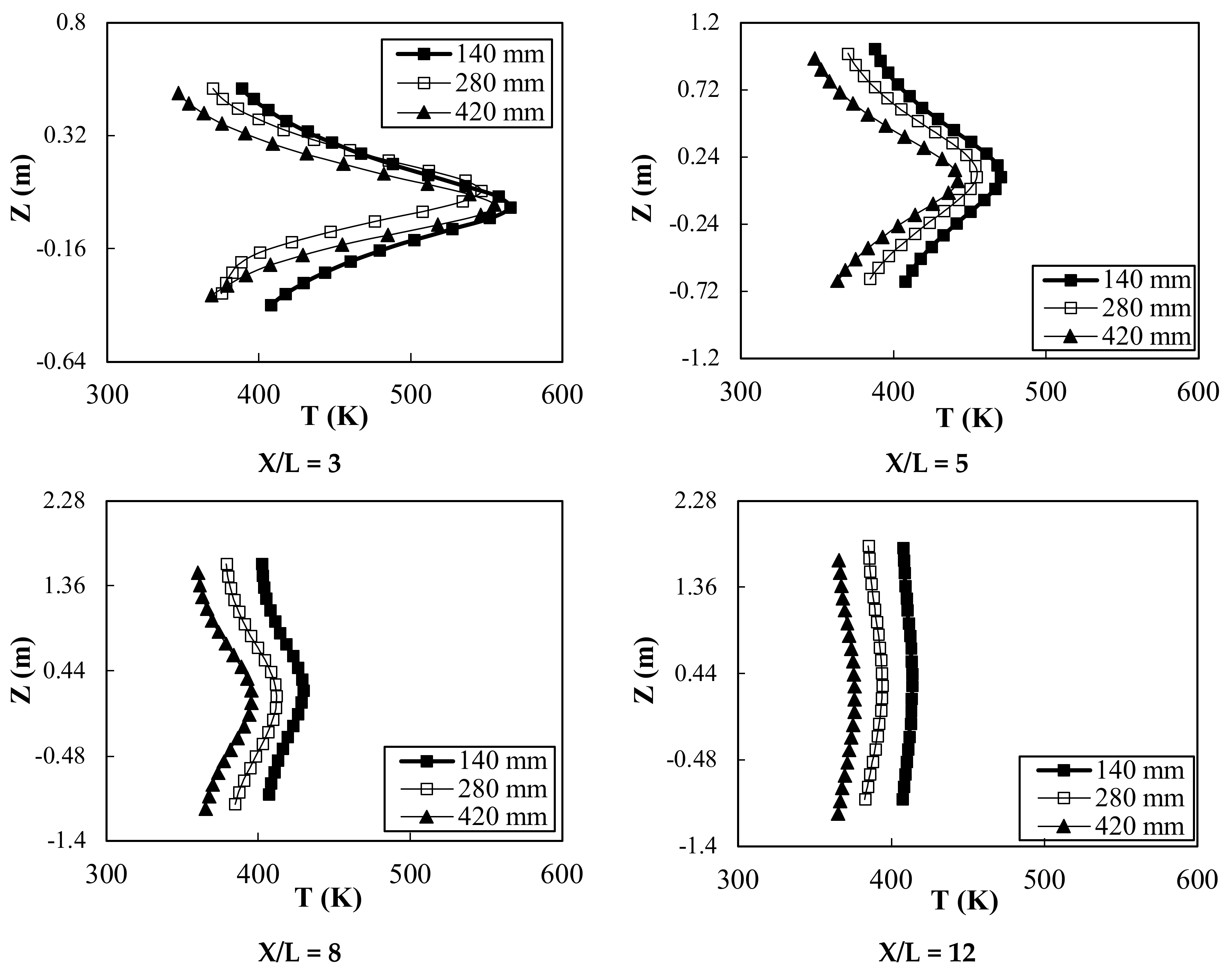
The temperature profiles at different locations at the jet centerline and at different aft-deck lengths are shown in Figure 27. The figure indicates that increasing the length of the aft-deck resulted in decreasing the temperature from the nozzle exit by up to 10 m. Increasing the aft-deck length leads to an increase in the wetted area and, hence, increases the expansion of the exhausted jet, as shown in Figure 24. This resulted in intensive mixing between the jet and ambient air, which resulted in reducing the temperature of the exhausted jet. Furthermore, with increasing the distance from the nozzle exit, the temperature reduced as the jet expanded more, as shown in velocity contours.
Figure 28a,b illustrate the velocity contour and velocity distribution, respectively, downstream at the nozzle exit. 
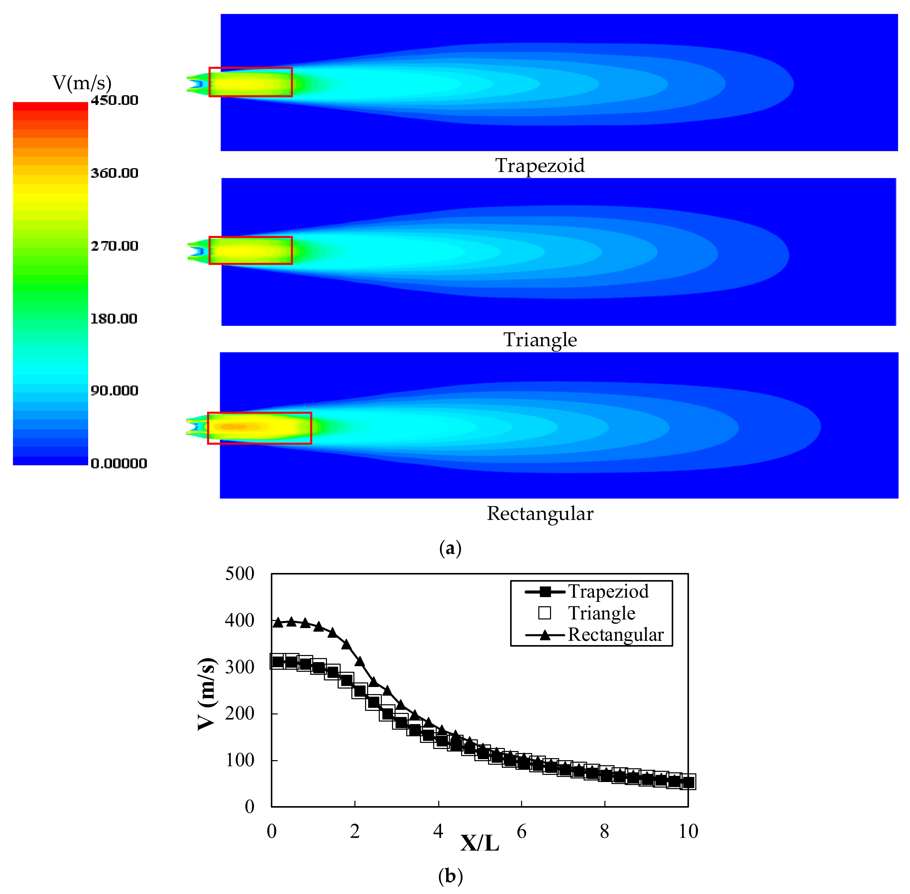
Figure 28a shows the exhausted jet indicated by velocity contours at a vertical plane for different aft-deck shapes. The velocity contour indicates that the potential core of the exhausted jet for the nozzle with a rectangular aft-deck was almost higher than that of the nozzle with a trapezoid or triangle aft-deck. The velocity distribution along the centerline of the exhausted jet is shown in Figure 28b. The velocity at the nozzle exit was the highest and gradually decreased with the increasing distance from the nozzle exit. Due to the momentum exchange, the surrounding air was entrained with the exhausted jet. As a consequence, the flow of the jet gradually increased in the axial direction, which led to the expansion of the jet volume and, hence, a decrease in the velocity. As shown by the velocity distribution, the velocity at the nozzle exit of the nozzle with a trapezoid and a triangle aft-deck was lower than that of the nozzle with a rectangular aft-deck shape; this also demonstrated that using both the triangle and trapezoid aft-deck could reduce the noise generated by the engine and improve the performance of the nozzle.
The temperature distribution along the centerline of the exhausted jet for different shapes of the aft-deck is shown in Figure 29. The figure shows that the temperature was the highest at the nozzle exit where the potential core region exited, and then the temperature gradually reduced with the increasing distance from the nozzle exit due to the mixing between the exhausted jet and ambient air. The figure demonstrates that using a nozzle with a trapezoid or triangle aft-deck can reduce the temperature at the nozzle exit compared to using a nozzle with a rectangular aft-deck. This can reduce the infrared radiation and hence improve the nozzle performance. Both the trapezoid and triangle aft-deck increased the projected area available for the exhausted jet to mix with the surrounding air, which enhanced the mixing process and led to the decreasing size and length of the potential core region, as shown in Figure 28.

5. Conclusions

The serpentine nozzle is of strategic interest to researchers and military forces because it can shield the high-temperature components of the engine. Most studies in the open literature only investigate the serpentine nozzle performance; however, in the actual aircraft, the serpentine nozzle is attached to the engine exhaust system. The engine exhaust system consists of a double duct, mixer, and tail cone. Furthermore, the serpentine nozzle performance can be further improved by adding an aft-deck to the end of the nozzle. Therefore, the main goal of this study was to investigate the performance of a serpentine nozzle considering the engine exhaust system and aft-deck and using the computational fluid dynamics technique. The main conclusions can be summarized in the following.
  • A new design of a mixer with a cone shape was used, and the effect of different mixer cone angles of 10°, 15°, and 20° was studied.
  • The importance of the aft-deck was indicated by comparing the performance of nozzles with and without an aft-deck. Then, the influence of aft-deck lengths and shapes was also investigated.
  • Increasing the mixer cone angle resulted in a decrease in the high-temperature core flow and an increase in the low-temperature bypass flow. The velocity inside the nozzle and at the exhausted jet decreased with the increasing mixer cone angle and could reduce the noise generated from engine exhaust systems.
  • Increasing the mixer cone angle resulted in a decrease in the internal temperature of the nozzle and at the exit jet, which could minimize the infrared radiation.
  • Compared to the nozzle without an aft-deck, the presence of an aft-deck resulted in a decrease in the pressure, temperature, and velocity inside the nozzle. The aft- deck also reduced the temperature of exhausted gases, which helped decrease infrared radiation. Furthermore, the aft-deck can decrease the velocity at the nozzle exit, which can decrease the noise generated from the nozzle.
  • The aft-deck length did not affect the internal flow characteristics. However, increasing the aft-deck length can decrease the temperature of the external jet, which can reduce infrared radiation.
  • The shape of the aft-deck affects the internal flow and exhaust jet characteristics. Using a trapezoid and triangle aft-deck improved the nozzle performance compared to a rectangular aft-deck. Using the aft-deck with trapezoid and triangle shapes reduced the velocity and temperature inside the nozzle, and the exhausted jet could reduce the noise and infrared radiation.

Author Contributions

H.M.A.A.: Conceptualization, Methodology, analysis, Investigation; B.-G.A.: resources, review and editing; J.L.: funding acquisition, project administration, supervision, review and editing. All authors have read and agreed to the published version of the manuscript.

Funding

This research received no external funding.

Data Availability Statement

The data that support the findings of this study are available from the corresponding author upon reasonable request.

Conflicts of Interest

The authors have no conflict to disclose.

References

  1. Sun, X.-l.; Wang, Z.-x.; Shi, J.-w.; Li, Z.; Liu, Z.-w. Experimental and computational investigation of double serpentine nozzle. Proc. Inst. Mech. Eng. Part G J. Aerosp. Eng. 2014, 229, 2035–2050. [Google Scholar] [CrossRef]
  2. Shan, Y.; Zhou, X.; Tan, X.; Zhang, J.; Wu, Y. Parametric Design Method and Performance Analysis of Double S-Shaped Nozzles. Int. J. Aerosp. Eng. 2019, 2019, 4694837. [Google Scholar] [CrossRef] [Green Version]
  3. Sun, X.-l.; Wang, Z.-x.; Li, Z.; Liu, Z.-w.; Shi, J.-w. Influences of Design Parameters on a Double Serpentine Convergent Nozzle. J. Eng. Gas Turbines Power 2016, 138, 072301. [Google Scholar] [CrossRef]
  4. Cheng, W.; Wang, Z.; Zhou, L.; Shi, J.; Sun, X. Infrared signature of serpentine nozzle with engine swirl. Aerosp. Sci. Technol. 2019, 86, 794–804. [Google Scholar] [CrossRef]
  5. Rajkumar, P.; Chandra, S.T.; Abhijit, K.; Bhavik, M.; Biju, U. Flow Characterization for a Shallow Single Serpentine Nozzle with Aft deck. J. Propuls. Power 2017, 33, 1–10. [Google Scholar] [CrossRef]
  6. Hamada, M.A.; Changwook, L.; Yechan, S.; Jeekeun, L. A computational study of two-dimensional serpentine nozzle performance with different annular mixer configurations. Int. J. Mech. Sci. 2021, 208, 106690. [Google Scholar]
  7. Sun, P.; Zhou, L.; Wang, Z.; Sun, X. Effect of Serpentine Nozzle on Bypass Ratio of Turbofan Engine Exhaust. In Proceedings of the American Institute of Aeronautics and Astronautics 2018 Joint Propulsion Conference, Cincinnati, OH, USA, 9–11 July 2018. [Google Scholar] [CrossRef]
  8. Chen, W.; Wang, Z.; Zhou, L.; Sun, X.; Shi, J. Influences of shield ratio on the infrared signature of serpentine nozzle. Aerosp. Sci. Technol. 2017, 71, 299–311. [Google Scholar] [CrossRef]
  9. Sun, X.; Wang, Z.; Zhou, L.; Shi, J.; Cheng, W. Internal flow and external jet characteristics of double serpentine nozzle with different aspect ratio. Proc. Inst. Mech. Part G J. Aerosp. Eng. 2017, 231, 1–15. [Google Scholar] [CrossRef]
  10. Sun, X.; Wang, Z.; Zhou, L.; Shi, J.; Cheng, W. Flow characteristics of double serpentine convergent nozzle with different inlet configuration. ASME J. Eng. Gas Turbines Power 2018, 140, 082602. [Google Scholar] [CrossRef]
  11. Zhang, Y.C.; Wang, Z.X.; Shi, J.W.; Fang, L.; Kong, D.Y. Analysis on flow and infrared radiation characteristics of double S-nozzle. J. Aerosp. Power 2013, 28, 2468–2474. [Google Scholar] [CrossRef]
  12. Yu, M.F.; Ji, H.H.; Li, N. Numerical analysis on infrared radiation characteristics of two-dimensional S-nozzle with small offset. J. Aerosp. Power 2015, 30, 2080–2087. [Google Scholar] [CrossRef]
  13. Wang, D.; Ji, H.H.; Hang, W. A serpentine 2-D exhaust system with high thrust and low infrared signature. J. Eng. Thermophys. 2017, 38, 1944–1951. [Google Scholar]
  14. Parviz, B.; James, J.M. Underexpanded Jet Development from a Rectangular Nozzle with Aft-Deck. AIAA J. 2015, 53, 1287–1298. [Google Scholar] [CrossRef] [Green Version]
  15. Wei, Y.B.; Ai, J.Q. Parameter design method of double juxtaposition 3-D asymmetric several S-shaped nozzles. J. Aerosp. Power 2015, 30, 271–280. [Google Scholar] [CrossRef]
  16. Nageswara, R.A.; Kushari, A. Underexpanded Supersonic Jets from Elliptical Nozzle with Aft-deck. J. Propuls. Power 2019, 36, 1–15. [Google Scholar] [CrossRef]
  17. Luo, M.D.; Ji, H.H.; Huang, W. Numerical evaluation on infrared radiant intensity of exhaust system of turbine engine without afterburning. J. Aerosp. Power 2007, 22, 1609–1616. [Google Scholar]
  18. Xie, Y.; Zhong, C.; Ruan, D.F.; Liu, K.; Zheng, B. Effect of core flow inlet swirl angle on performance of lobed mixing exhaust system. J. Mech. 2016, 32, 325–337. [Google Scholar] [CrossRef]
  19. Li, Y.; Yang, Q. Influence on radar cross-section of S-shaped two-dimensional convergent nozzles with different outlet width-height radios. J. Aerosp Power 2014, 29, 645–651. [Google Scholar] [CrossRef]
  20. Zhang, J.; Xie, Z. Three-Dimensional Computational Study for Flow Fields within Forced Lobe Mixer; ISABE Paper 2003-1104; ISABE: Cleveland, OH, USA, 2003. [Google Scholar]
  21. Shan, Y.; Zhang, J.Z. Numerical investigation of flow mixture enhancement and infrared radiation shield by lobed forced mixer. Appl. Therm. Eng. 2009, 29, 3687–3695. [Google Scholar] [CrossRef]
  22. Liu, C.; Ji, H. Numerical simulation on infrared radiation characteristics of serpentine 2-D nozzle. J. Aerosp Power 2013, 28, 482–1488. [Google Scholar] [CrossRef]
  23. Liu, C.; Ji, H. Numerical simulation on infrared radiant characteristics of 2D S-nozzle. J. Eng. 2010, 31, 1567–1570. [Google Scholar]
  24. Kline, S.J.; McClintock, F.A. Describing uncertainties in single sample experiments. Mech. Eng. 1953, 75, 3–8. [Google Scholar]
Figure 1. The CAD model and schematic of the serpentine nozzle with conical mixer under study.
Aerospace 10 00076 g001
Figure 2. Grid system used in the simulations [6].
Aerospace 10 00076 g002
Figure 3. Variation of the frontal area along the nozzle length.
Aerospace 10 00076 g003
Figure 4. Flow characteristics inside the nozzle for different grids.
Aerospace 10 00076 g004aAerospace 10 00076 g004b
Figure 5. Photo of serpentine nozzle used in the experiments [6].
Aerospace 10 00076 g005
Figure 6. Axial distribution of the pressure at the upper and lower nozzle walls for experiments and simulations [6].
Aerospace 10 00076 g006
Figure 7. Pressure distribution on the upper and lower nozzle walls for different mixer cone angles.
Aerospace 10 00076 g007
Figure 8. Velocity contour and distribution at different locations along the nozzle length for different mixer cone angles.
Aerospace 10 00076 g008
Figure 9. Turbulent kinetic energy contour and distribution at different locations along the nozzle length for different mixer cone angles.
Aerospace 10 00076 g009
Figure 10. Thrust force distribution at different locations along the nozzle length for different mixer cone angles.
Aerospace 10 00076 g010
Figure 11. Temperature contour and distribution at different locations along the nozzle length for different mixer cone angles.
Aerospace 10 00076 g011
Figure 12. Velocity contour at the vertical plan downstream nozzle exit for different mixer cone angles.
Aerospace 10 00076 g012
Figure 13. Velocity distribution at the centerline of the exhausted jet for different mixer cone angles.
Aerospace 10 00076 g013
Figure 14. Constrain streamlines at the vertical plane for different mixer cone angles.
Aerospace 10 00076 g014
Figure 15. M distribution at the centerline of the exhausted jet for different mixer cone angles.
Aerospace 10 00076 g015
Figure 16. Temperature distribution at the centerline of the exhausted jet for different mixer cone angles.
Aerospace 10 00076 g016
Figure 17. Internal flow characteristics at different sections along the length of the nozzle without and with an aft-deck. (a) Pressure distribution, (b) Velocity distribution, (c) M distribution, (d) Temperature distribution.
Aerospace 10 00076 g017
Figure 18. Velocity magnitude contours for nozzle without and with an aft-deck.
Aerospace 10 00076 g018
Figure 19. Radial profiles of velocity magnitude at different locations along jet length.
Aerospace 10 00076 g019
Figure 20. Temperature radial profiles at different locations along jet length. Effect of the length and shape of the aft-deck.
Aerospace 10 00076 g020
Figure 21. Different shapes of aft-deck used in the study.
Aerospace 10 00076 g021
Figure 22. The velocity and temperature profiles inside the nozzle at different axial positions: (a,b) For different aft-deck lengths, (c,d) For different aft-deck shapes.
Aerospace 10 00076 g022
Figure 23. Temperature contour inside the nozzle at different axial locations for different aft-deck shapes.
Aerospace 10 00076 g023
Figure 24. Velocity contour of the nozzle at different aft-deck lengths.
Aerospace 10 00076 g024
Figure 25. Radial velocity distribution at different axial lengths along the jet centerline for different aft-deck lengths.
Aerospace 10 00076 g025
Figure 26. Jet half-length distributions at different axial lengths for different aft-deck lengths.
Aerospace 10 00076 g026
Figure 27. Temperature distribution at different locations along the jet centerline for different aft-deck lengths.
Aerospace 10 00076 g027
Figure 28. Velocity contour and (a) velocity distribution, (b) at the exhausted jet for different aft-deck shapes.
Aerospace 10 00076 g028
Figure 29. Temperature distribution at the centerline of the exhausted jet for different aft-deck shapes.
Aerospace 10 00076 g029
Table 1. Boundary conditions at different regions used in the simulations.
RegionTypePressure (Bar)Temperature (K)Turbulent Intensity
CorePressure inlet0.458000.01
BypassPressure inlet0.483300.01
OutletPressure outlet1.0132880.01
Table 2. Properties of air used in the calculations.
PropertyValueUnit
Dynamic viscosity1.85508 × 10−5Pa·s
Molecular weight28.9664kg/kmol
Specific heat1003.62J/kg·K
Thermal conductivity0.0260305W/m·K
Prandtl Number0.9-
Table 3. The flow rates at core and bypass regions for different mixer cone angles.
Cone AngleCore Flowrate (kg/s)Bypass Flowrate (kg/s)Total Flowrate (kg/s)
10°3.082730.08
15°2.1628.3530.46
20°1.2729.1730.44
Disclaimer/Publisher’s Note: The statements, opinions and data contained in all publications are solely those of the individual author(s) and contributor(s) and not of MDPI and/or the editor(s). MDPI and/or the editor(s) disclaim responsibility for any injury to people or property resulting from any ideas, methods, instructions or products referred to in the content.

