
Microstructural Evolution and Mechanical Properties of Ti2AlNb/GH99 Superalloy Brazed Joints Using TiZrCuNi Amorphous Filler Alloy

 , and
, and
Abstract
:1. Introduction
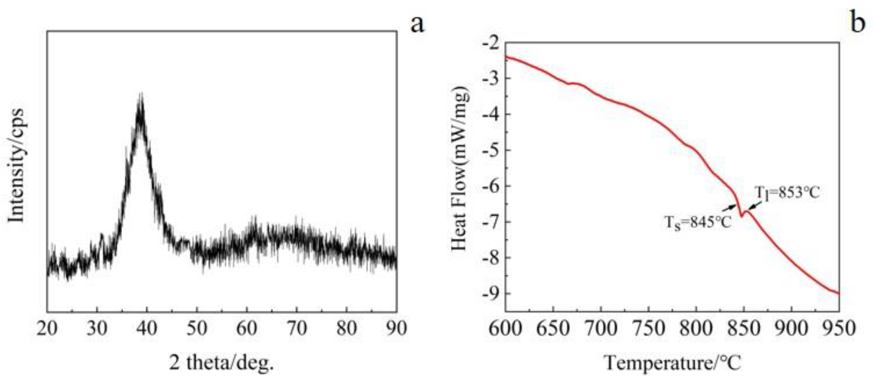
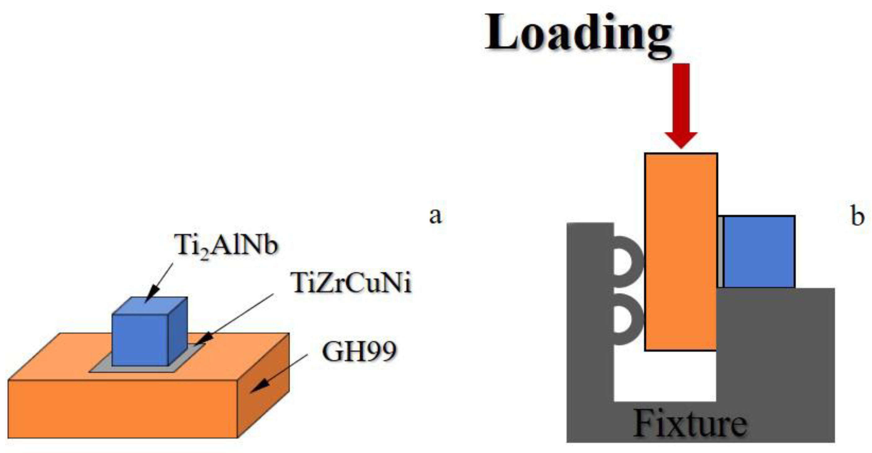
2. Experiment
3. Results and Discussion
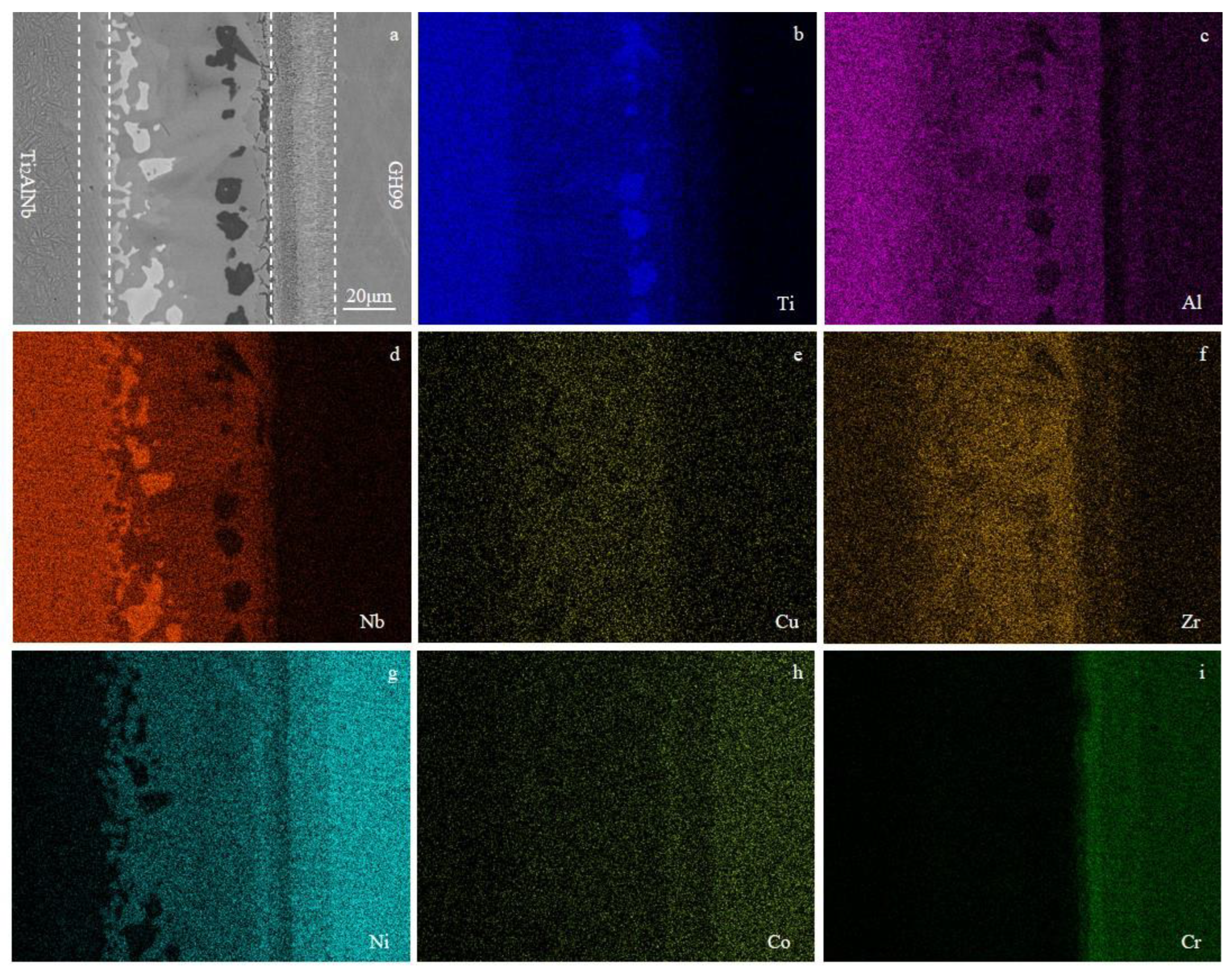
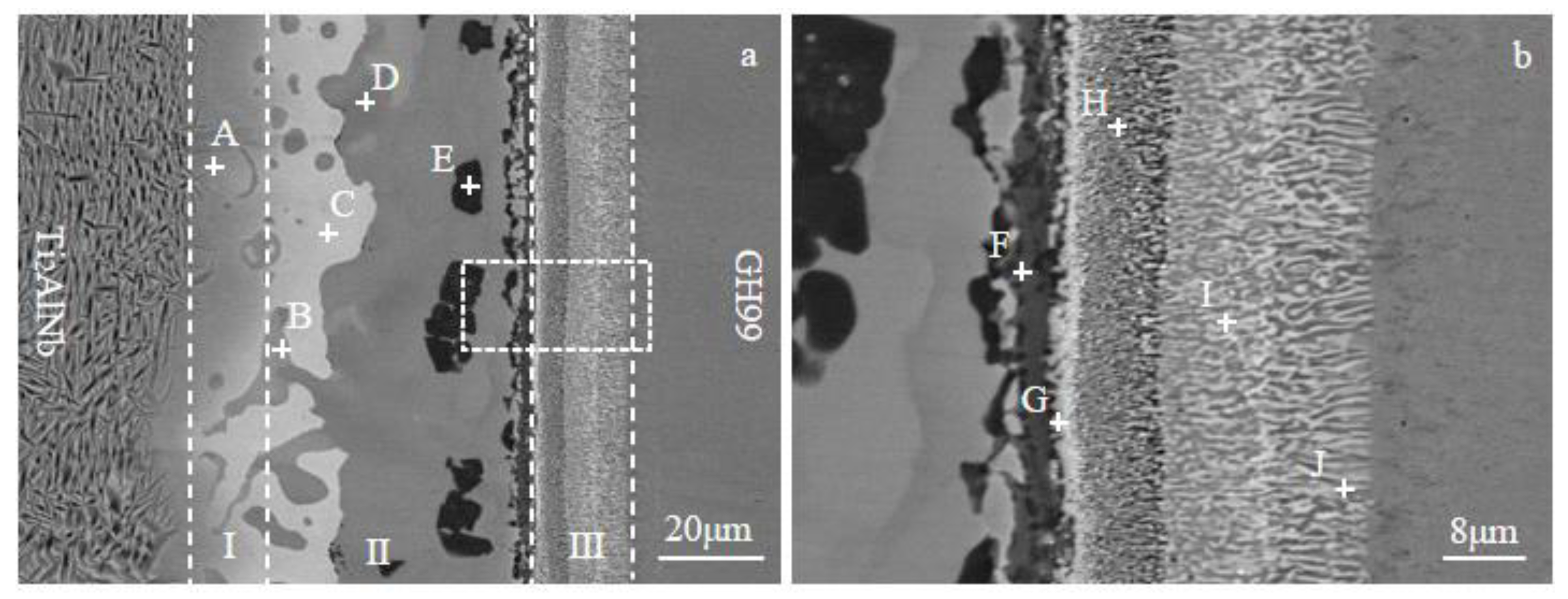
3.1. Typical Interfacial Microstructure of Ti2AlNb/TiZrCuNi/GH99 Joint
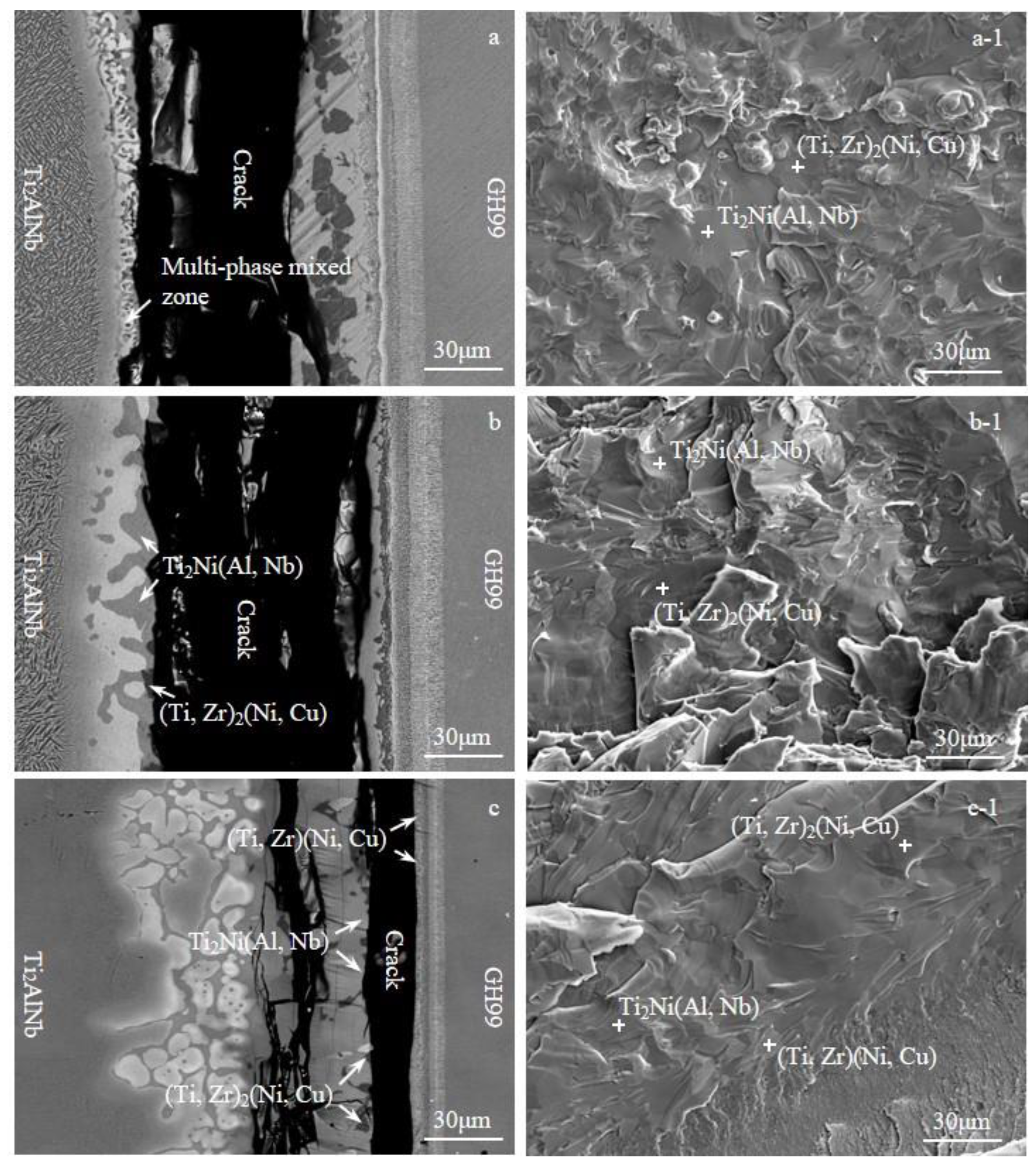
3.2. Effect of Brazing Parameters on the Microstructure of Ti2AlNb/GH99 Brazed Joints
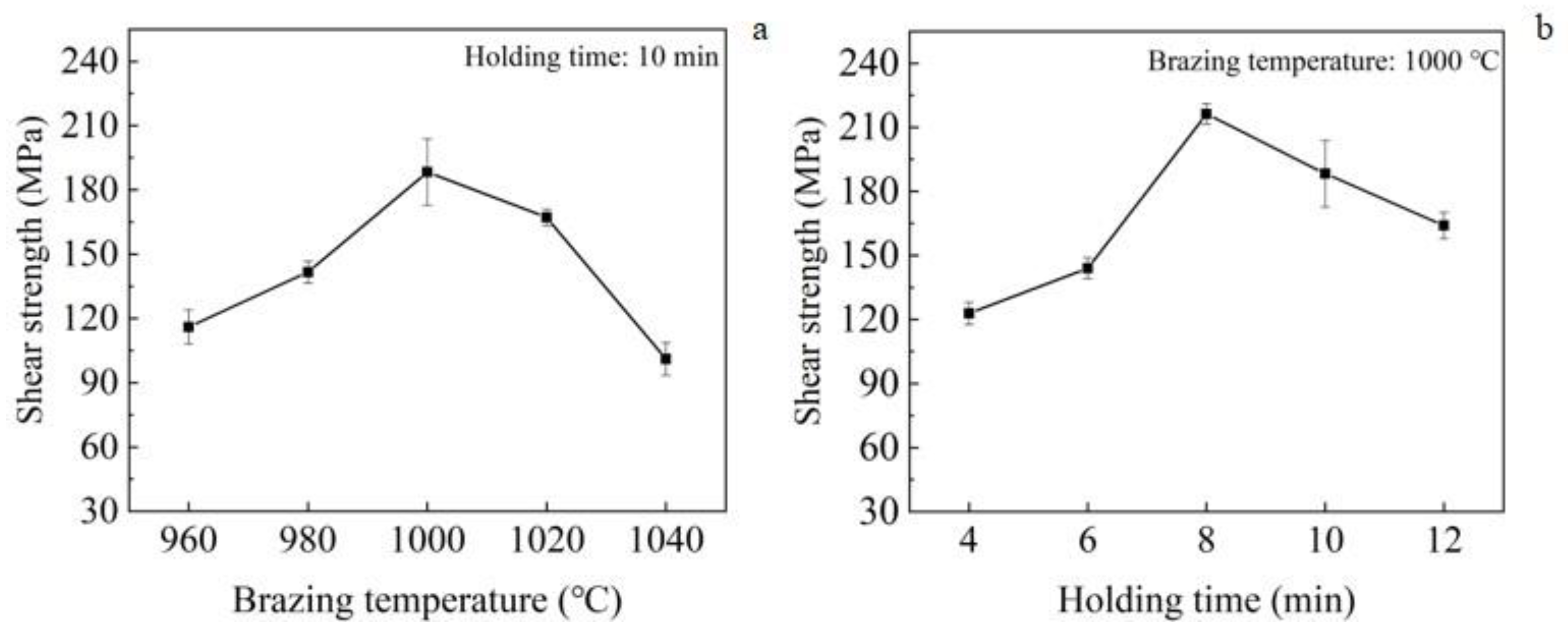
3.3. Effect of Brazing Parameters on the Mechanical Properties of Ti2AlNb/GH99 Brazed Joints
4. Conclusions
- (1)
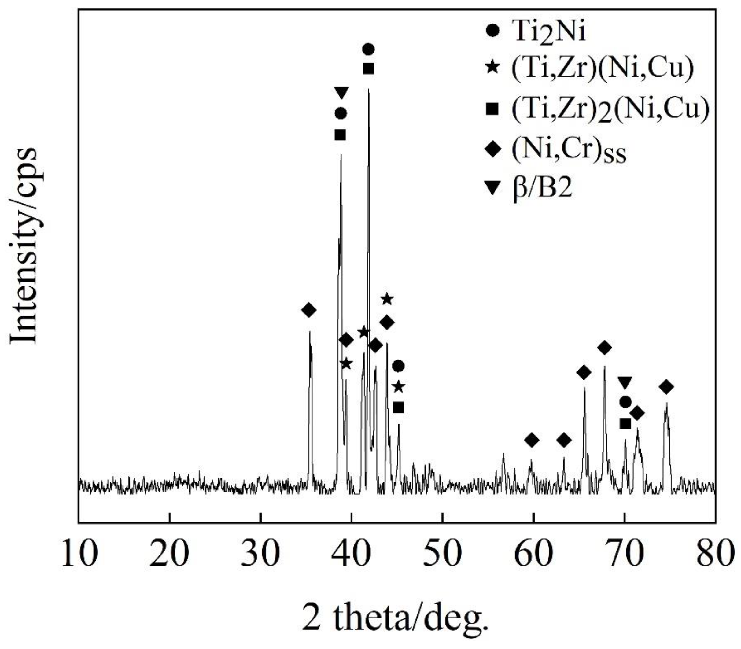
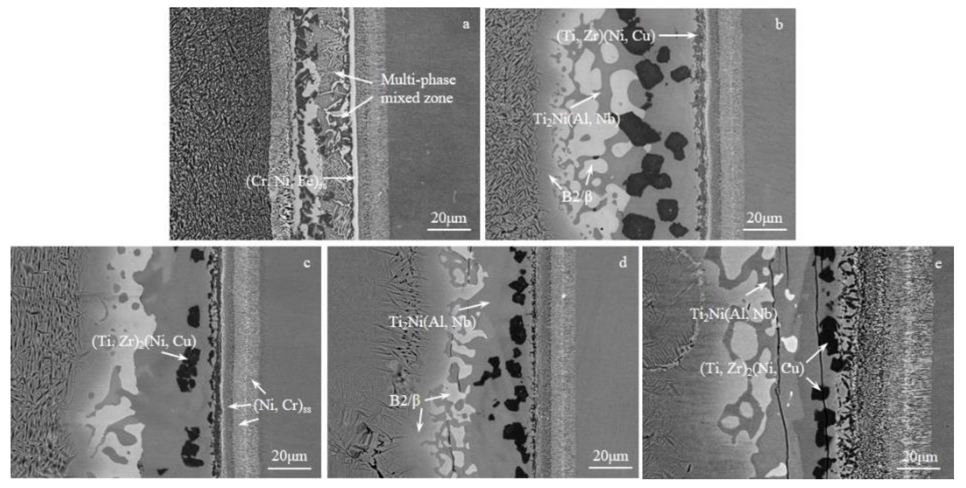
- The characteristic interfacial microstructure of Ti2AlNb/GH99 joint brazd with TiZrCuNi filler brazed at 1000 °C for 10 min was Ti2AlNb alloy/B2/β/Ti2Ni (Al, Nb) + B2/β + (Ti, Zr)2(Ni, Cu) + (Ti, Zr)(Ni, Cu)/(Cr, Ni, Ti) ss + (Ni, Cr) ss/GH99 alloy. The brazing seam was mainly composed of Ti2Ni (Al, Nb) and (Ti, Zr)2(Ni, Cu) phases.
- (2)
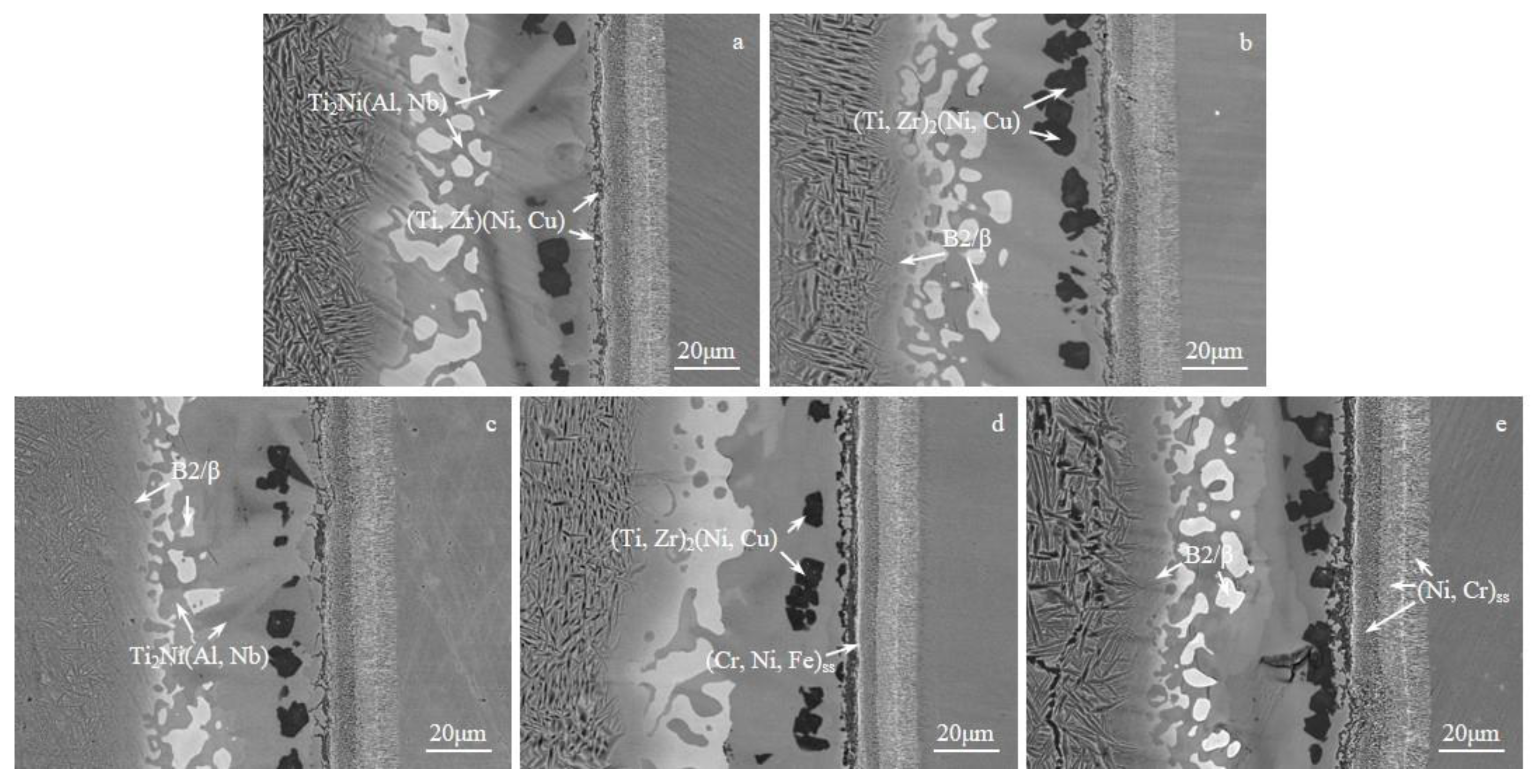
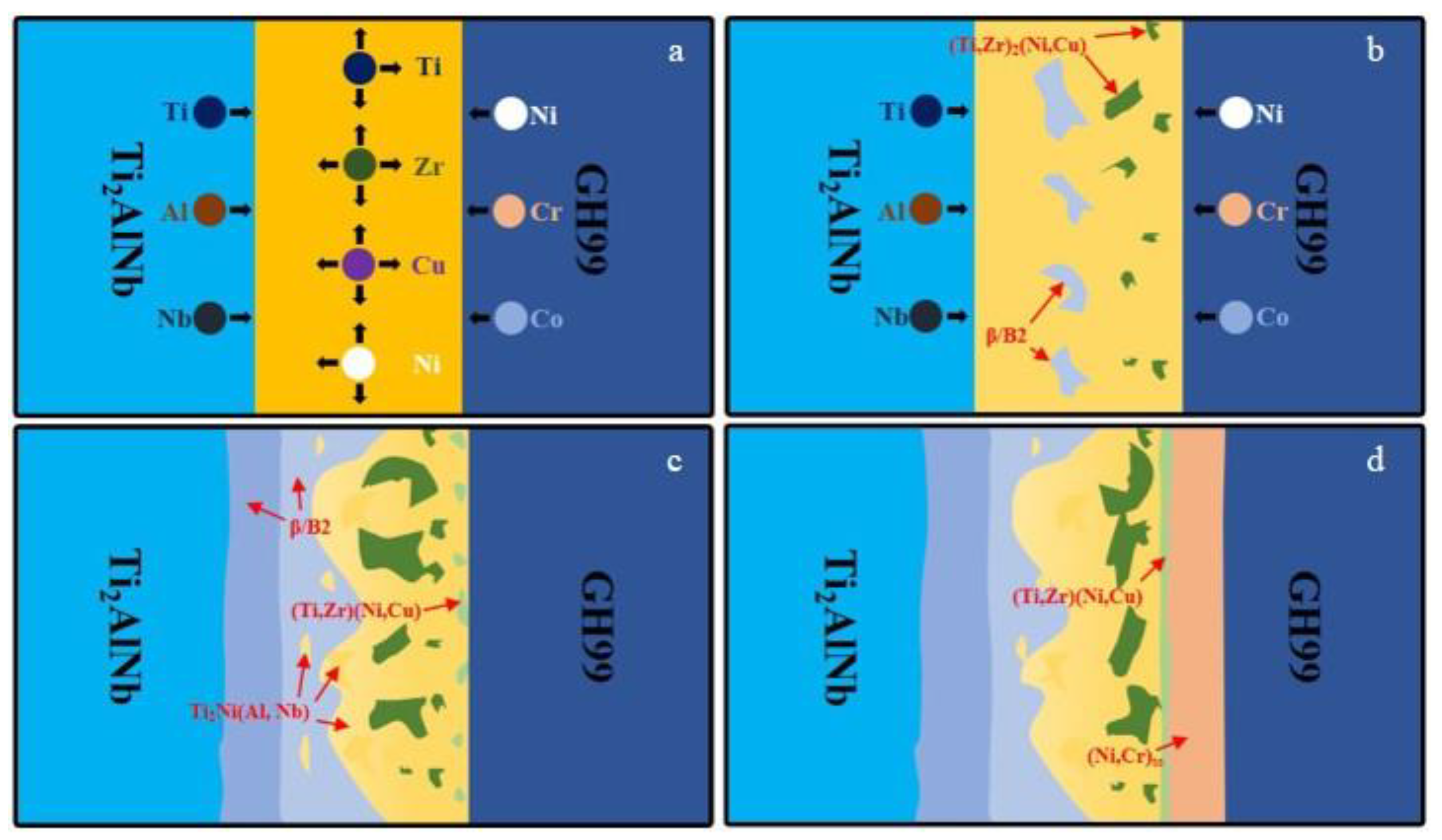
- Higher brazing temperature or longer holding time promoted atomic diffusion between the parent metals and the filler alloy, which enhanced the metallurgical reaction between them, resulting in the increase in Ti2Ni (Al, Nb) phase and the coarsening of (Ti, Zr)2(Ni, Cu) phase.
- (3)
- The existence of coarse (Ti, Zr)2(Ni, Cu) phase and continuous Ti2Ni (Al, Nb) phase in the brazing seam resulted in cracks that could easily sprout and expand in these brittle phases, and the performance of Ti2AlNb/GH99 brazed joint was decreased dramatically. The joints reached a maximum average shear strength of ~216.2 MPa when brazed at 1000 °C for 8 min. The fracture results showed that the cracks extend in the brazed seam.
Author Contributions
Funding
Data Availability Statement
Conflicts of Interest
References
- Pollock, T.M.; Tin, S. Nickel-based superalloys for advanced turbine engines: Chemistry, microstructure, and properties. J. Propul. Power 2006, 22, 361–374. [Google Scholar] [CrossRef]
- Wang, P.; Chen, D.; Fan, J.; Sun, K.; Wu, S.; Li, J.H.; Sun, Y. Study on the influence of process parameters on high performance Ti-6Al-4V parts in laser powder bed fusion. Rapid Prototyp. J. 2022; ahead-of-print. [Google Scholar] [CrossRef]
- Wang, Y.; Shao, W.Z.; Zhen, L.; Yang, L.; Zhang, X.M. Flow behavior and microstructures of superalloy 718 during high temperature deformation. Mater. Sci. Eng. A-Struct. Mater. Prop. Microstruct. Process. 2008, 497, 479–486. [Google Scholar] [CrossRef]
- Nespoli, A.; Bennato, N.; Villa, E.; Passaretti, F. Study of anisotropy through microscopy, internal friction and electrical resistivity measurements of Ti-6Al-4V samples fabricated by selective laser melting. Rapid Prototyp. J. 2022, 28, 1060–1075. [Google Scholar] [CrossRef]
- Farzaneh, A.; Khorasani, M.; Farabi, E.; Gibson, I.; Leary, M.; Ghasemi, A.M.H.; Rolfe, B.F. Sandwich structure printing of Ti-Ni-Ti by directed energy deposition. Virtual Phys. Prototyp. 2022, 17, 1006–1030. [Google Scholar] [CrossRef]
- Chen, R.R.; Dong, S.L.; Guo, J.J.; Ding, H.S.; Su, Y.Q.; Fu, H.Z. Microstructure evolution and mechanical properties of directionally-solidified TiAlNb alloy in different temperature gradients. J. Alloys Compd. 2015, 648, 667–675. [Google Scholar] [CrossRef]
- Kesler, M.S.; Goyel, S.; Ebrahimi, F.; Manuel, M.V. Effect of microstructural parameters on the mechanical behavior of TiAlNb(Cr,Mo) alloys with gamma plus sigma microstructure at ambient temperature. J. Alloys Compd. 2017, 695, 2672–2681. [Google Scholar] [CrossRef] [Green Version]
- Cai, X.Q.; Wang, Y.; Yang, Z.W.; Wang, D.P.; Liu, Y.C. Transient liquid phase (TLP) bonding of Ti2AlNb alloy using Ti/Ni interlayer: Microstructure characterization and mechanical properties. J. Alloys Compd. 2016, 679, 9–17. [Google Scholar] [CrossRef]
- Prasad, K.S.; Rao, C.S.; Rao, D.N. Effect of process parameters of pulsed current micro plasma arc welding on weld pool geometry of Inconel 625 welds. Met. Mater. 2012, 50, 175–181. [Google Scholar] [CrossRef] [Green Version]
- Cai, X.L.; Sun, D.Q.; Li, H.M.; Meng, C.; Wang, L.; Shen, C.J. Dissimilar joining of TiAl alloy and Ni-based superalloy by laser welding technology using V/Cu composite interlayer. Opt. Laser Technol. 2019, 111, 205–213. [Google Scholar] [CrossRef]
- Gaikwad, V.T.; Mishra, M.K.; Hiwarkar, V.D.; Singh, R.K.P. Microstructure and mechanical properties of friction welded carbon steel (EN24) and nickel-based superalloy (IN718). Int. J. Miner. Metall. Mater. 2021, 28, 111–119. [Google Scholar] [CrossRef]
- Ren, X.; Ren, H.; Shang, Y.; Xiong, H.; Zhang, K.; Zheng, J.; Liu, D.; Lin, J.; Jiang, J. Microstructure evolution and mechanical properties of Ti2AlNb/TiAl brazed joint using newly-developed Ti–Ni–Nb–Zr filler alloy. Prog. Nat. Sci. Mater. Int. 2020, 30, 410–416. [Google Scholar] [CrossRef]
- Dong, D.; Shi, K.; Zhu, D.; Liang, Y.; Wang, X.; Wei, Z.; Lin, J. Microstructure evolution and mechanical properties of high Nb–TiAl alloy/GH4169 joints brazed using CuTiZrNi amorphous filler alloy. Intermetallics 2021, 139, 107351. [Google Scholar] [CrossRef]
- Sequeiros, E.W.; Guedes, A.; Pinto, A.M.P.; Vieira, M.F.; Viana, F. Microstructure and Strength of gamma-TiAl alloy/Inconel 718 brazed joints. In Proceedings of the 6th International Materials Symposium (MATERIALS 2011)/15th Meeting of SPM, Guimaraes, Portugal, 18–20 April 2011; pp. 835–840. [Google Scholar]
- Ren, H.S.; Xiong, H.P.; Long, W.M.; Chen, B.; Shen, Y.X.; Pang, S.J. Microstructures and mechanical properties of Ti3Al/Ni-based superalloy joints brazed with AuNi filler metal. J. Mater. Sci. Technol. 2019, 35, 2070–2078. [Google Scholar] [CrossRef]
- Liu, D.; Song, Y.; Shi, B.; Zhang, Q.; Song, X.; Niu, H.; Feng, J. Vacuum brazing of GH99 superalloy using graphene reinforced BNi-2 composite filler. J. Mater. Sci. Technol. 2018, 34, 1843–1850. [Google Scholar] [CrossRef]
- Li, X.; Li, L.; Hu, K.; Qu, S. Vacuum brazing of TiAl-based intermetallics with Ti–Zr–Cu–Ni–Co amorphous alloy as filler metal. Intermetallics 2015, 57, 7–16. [Google Scholar] [CrossRef]
- Wang, G.; Wu, P.; Wang, W.; Zhu, D.D.; Tan, C.Q.; Su, Y.S.; Shi, X.Y.; Cao, W. Brazing Ti-48Al-2Nb-2Cr Alloys with Cu-Based Amorphous Alloy Filler. Appl. Sci. 2018, 8, 920. [Google Scholar] [CrossRef] [Green Version]
- Ren, H.; Ren, X.; Long, W.; Chen, B.; Pang, S.; Xiong, H. Formation mechanism of interfacial microstructures and mechanical properties of Ti2AlNb/Ni-based superalloy joints brazed with NiCrFeSiB filler metal. Prog. Nat. Sci. Mater. Int. 2021, 31, 310–318. [Google Scholar] [CrossRef]
- Raghavan, V. Handbook of ternary alloy phase diagrams. J. Phase Equilib. Diffus. 2006, 27, 371. [Google Scholar] [CrossRef] [Green Version]
- Lee, M.K.; Kim, K.H.; Lee, J.G.; Rhee, C.K. Growth of isothermally-solidified titanium joints using a multi-component Zr-Ti-Cu-Ni-Be amorphous alloy as a brazing filler. Mater. Charact. 2013, 80, 98–104. [Google Scholar] [CrossRef]
- Li, H.; Wei, H.; He, P.; Lin, T.; Feng, J.; Huang, Y. Effects of alloying elements in GH99 superalloy on microstructure evolution of reactive brazing TiAl/GH99 joints. Intermetallics 2013, 34, 69–74. [Google Scholar] [CrossRef]
- He, P.; Wang, J.; Lin, T.; Li, H. Effect of hydrogen on diffusion bonding of TiAl-based intermetallics and Ni-based superalloy using hydrogenated Ti6Al4V interlayer. Int. J. Hydrogen Energy 2014, 39, 1882–1887. [Google Scholar] [CrossRef]
- Hayama, A.O.F.; Andrade, P.N.; Cremasco, A.; Contieri, R.J.; Afonso, C.R.M.; Caram, R. Effects of composition and heat treatment on the mechanical behavior of Ti–Cu alloys. Mater. Des. 2014, 55, 1006–1013. [Google Scholar] [CrossRef]
- Schuster, J.C.; Pan, Z.; Liu, S.; Weitzer, F.; Du, Y. On the constitution of the ternary system Al–Ni–Ti. Intermetallics 2007, 15, 1257–1267. [Google Scholar] [CrossRef]
- Zhang, B.C.; Chen, J.; Coddet, C. Microstructure and Transformation Behavior of in-situ Shape Memory Alloys by Selective Laser Melting Ti-Ni Mixed Powder. J. Mater. Sci. Technol. 2013, 29, 863–867. [Google Scholar] [CrossRef]


| Ti | Zr | Ni | Cu | Al | Nb | Cr | W | Co | Mo | |
|---|---|---|---|---|---|---|---|---|---|---|
| Ti2AlNb (at.%) | Bal. | — | — | — | 11.72 | 32.31 | — | — | — | 1.7 |
| GH99 (at.%) | 1.42 | — | Bal. | — | 1.05 | — | 18.32 | 8.23 | 6.56 | 2.93 |
| Spots | Al | Zr | Nb | Ti | Cr | Co | Ni | Cu | Possible Phase |
|---|---|---|---|---|---|---|---|---|---|
| A | 18.33 | 1.74 | 22.99 | 52.50 | 0.44 | 0.88 | 2.37 | 0.75 | β/B2 |
| B | 16.08 | 6.17 | 11.56 | 39.57 | 0.40 | 1.34 | 20.41 | 4.47 | Ti2Ni (Al, Nb) |
| C | 12.56 | 2.84 | 29.52 | 52.80 | 0.50 | 0.09 | 1.33 | 0.36 | β/B2 |
| D | 15.07 | 6.33 | 10.45 | 40.53 | 0.43 | 1.63 | 20.92 | 4.64 | Ti2Ni (Al, Nb) |
| E | 0.24 | 1.63 | 1.26 | 63.14 | 0.36 | 2.40 | 27.95 | 3.02 | (Ti, Zr)2(Ni, Cu) |
| F | 6.41 | 2.01 | 1.39 | 36.40 | 0.35 | 4.76 | 47.45 | 1.14 | (Ti, Zr)(Ni, Cu) |
| G | 5.92 | 5.36 | 5.93 | 19.74 | 29.76 | 5.65 | 27.08 | 0.56 | (Cr, Ni, Ti) ss |
| H | 15.43 | 2.70 | 2.03 | 15.30 | 28.99 | 3.90 | 31.30 | 0.35 | (Ni, Cr) ss |
| I | 2.24 | 2.08 | 1.58 | 14.12 | 20.26 | 3.74 | 55.57 | 0.41 | (Ni, Cr) ss |
| J | 10.26 | 0.88 | 1.31 | 4.74 | 21.87 | 5.22 | 55.45 | 0.26 | (Ni, Cr) ss |
Disclaimer/Publisher’s Note: The statements, opinions and data contained in all publications are solely those of the individual author(s) and contributor(s) and not of MDPI and/or the editor(s). MDPI and/or the editor(s) disclaim responsibility for any injury to people or property resulting from any ideas, methods, instructions or products referred to in the content. |
© 2023 by the authors. Licensee MDPI, Basel, Switzerland. This article is an open access article distributed under the terms and conditions of the Creative Commons Attribution (CC BY) license (https://creativecommons.org/licenses/by/4.0/).
Share and Cite
Cai, J.; Hu, S.; Liu, H.; Lin, D.; Fu, W.; Song, X. Microstructural Evolution and Mechanical Properties of Ti2AlNb/GH99 Superalloy Brazed Joints Using TiZrCuNi Amorphous Filler Alloy. Aerospace 2023, 10, 73. https://doi.org/10.3390/aerospace10010073
Cai J, Hu S, Liu H, Lin D, Fu W, Song X. Microstructural Evolution and Mechanical Properties of Ti2AlNb/GH99 Superalloy Brazed Joints Using TiZrCuNi Amorphous Filler Alloy. Aerospace. 2023; 10(1):73. https://doi.org/10.3390/aerospace10010073
Chicago/Turabian StyleCai, Junjie, Shengpeng Hu, Hongbing Liu, Danyang Lin, Wei Fu, and Xiaoguo Song. 2023. "Microstructural Evolution and Mechanical Properties of Ti2AlNb/GH99 Superalloy Brazed Joints Using TiZrCuNi Amorphous Filler Alloy" Aerospace 10, no. 1: 73. https://doi.org/10.3390/aerospace10010073