Article

Influence of Spinner Shape on Droplet Impact over Rotating Spinners

1
Research Institute of Aero-Engine, Beihang University, Beijing 100191, China
2
McCormick School of Engineering, Northwestern University, Evanston, IL 60208, USA
*
Author to whom correspondence should be addressed.
Aerospace 2023, 10(1), 68; https://doi.org/10.3390/aerospace10010068
Submission received: 2 December 2022 / Revised: 24 December 2022 / Accepted: 6 January 2023 / Published: 9 January 2023
(This article belongs to the Special Issue Advances in Aerospace Sciences and Technology III)

Abstract

:
Droplet impact affects water collection, which is the key to investigating the icing process on an aero-engine spinner. Different from a stationary spinner, droplet impact is affected by Coriolis acceleration and centrifugal acceleration on rotating aero-engine spinners, showing different impact dynamics. Based on the Eulerian method, using the rotating coordinate system we numerically investigated droplet impact characteristics on three different shapes of aero-engine spinners using ANSYS Fluent. The results indicate that the impact area covered all the windward surface on the conical spinner, and only covered the windward surface prior to the impingement limit of the elliptical spinner and the coniptical spinner. The sensitivity of water collection to inflow velocity declined in the order of coniptical the spinner, the elliptical spinner, and the conical spinner. In addition, the elliptical region could effectively improve aerodynamic performance, as shown in a lower total pressure loss through the spinner. This work is relevant to the anti-icing system of a rotating aero-engine spinner.

1. Introduction

When the windward surface of an aircraft passes through clouds, supercooled droplets adhere to the solid surface and freeze when the surface temperature is far below the freezing point of water. Icing is one of the common causes of aviation accidents [1], and the icing problem of aero-engines is particularly serious [2]. Ice reduces the flow area, changes the natural frequency and destroys the dynamic balance of the rotor. Falling ice may damage the blades or cause surge [3]. In aero-engines, icing mainly occurs at the inlet lip, rotating spinner and the first-stage rotor blades. As the front part of the engine, the rotating spinner has a serious icing phenomenon. Therefore, to reduce the danger of aero-engine icing, it is necessary to consider the influence of the rotating spinner on icing.
Previous work [4,5,6,7] has been done in solving the problems of aircraft icing. Once ice has formed, a common removal technique is the hot-air-based anti-icing system. Al-Khalil et al. [4] established an efficient numerical simulation method for estimating the hot-air-based anti-icing system for engine intake at subsonic speeds, pointing out that the method could be applied to airfoils and other components. Li et al. [5] carried out air-intake guide vane deicing experiments based on hot air. The results showed that when reasonable parameters of hot air are set to provide enough heat flux through guide vane, the system could achieve complete deicing of the guide vane, and the heat utilization efficiency was high. Another common de-icing technique is the electric-thermal anti-icing system. Jung et al. [6] developed a meta-model for icing and accurately evaluated an electric heating anti-icing system on two-dimensional airfoil and intakes of rotor engines. Gutiérrez et al. [7] used a liquid film model and a robust evaporation model to solve energy conservation laws and compute aerodynamic quantities; the results agree well with experimental results. The above active anti-icing systems reduce the efficiency of the engine [8]. Passive anti-icing technology, which focuses on interfering with the icing process instead of relying on active heating, has received more attention. The key to developing both active and passive anti-icing technology is to have a comprehensive understanding of the droplet impingement dynamics and the icing process on stationary and rotating components.
A number of researchers have investigated icing on stationary components, such as the airfoil and inlet lip. Ahn et al. [9] numerically and experimentally demonstrated that droplet size has a great influence on icing, and its influence increases with the growth of the droplet size at the air intake of a rotorcraft. W. Dong et al. [10] used a wind tunnel to measure the main characteristics of ice growth and ice type under different temperature, inflow velocity and water content conditions on engine inlet lips. Experimental results showed that water flow patterns, temperature distribution and ice shapes are depended on the parameter of freestream.
For rotating components, although some conclusions made on stationary parts still hold, the freezing mechanism is complicated by centrifugal and Coriolis forces. Recently, several studies have documented the icing characteristics on rotating blades [11,12], and on rotating spinners [13,14,15,16]. Bidwell et al. [13] found that the extent of icing of the spinner increases with the increase of droplet size, while that on the downstream components decreases. However, once the increasing of droplets size causes splashing, the icing amount on upstream components shifts to the downstream components. Li et al. [14] studied the transient icing process on rotating spinners and fan blades. It was found that different combinations of temperature and water content produce different icing geometry characteristics. Feather-like icicles are formed due to centrifugal force under glaze icing conditions, while the ice profile is consistent with the engine surface under rime ice conditions. Zheng et al. [15] argued that temperature determines the freezing rate, and the fluctuation of the rate leads to the formation of icicles. The rotation speed determines the angle and length of the icicles, and affects ice shedding. Mu et al. [16] suggested that rotation would strengthen ice accumulation and greatly affect the uniformity of icing in the case of incoming flow with attack angle.
A few experimental works have been devoted to the effect of spinner shape on icing. Li et al. [17] monitored the ice accumulation process using three types of spinners and measured their icing rates, finding that the amount of icing, the cover area, and the position of the icicles are closely related to the spinner shape. According to the study of Hu et al. [18], the cone angle of the conical spinner has a decisive influence on the thickness of the ice, ice shedding and the occurrence of icicles. Linke [19] observed that ice on elliptical-shaped spinner is the thickest among all spinners.
Numerical simulation of the icing process on a rotating spinner is complicated, and is affected by droplet impact [20], the flowing film [21], and thermodynamics of icing [22]. Distinguishing the influence of these factors on the icing process is important in understand the principles of engine icing. Simulation of droplet impingement mainly focuses on impingement range and the amount of adhesion of droplets, which should be basically consistent with the icing range and icing amount. When designing anti-icing systems, this can be used as a reference for preliminary design, such as locating hydrophobic coatings or heating devices, and estimating energy consumption. At the same time, the results of water droplet impact can be used as the boundary conditions of the heat transfer calculation, which is the premise of accurate simulation of icing phenomenon. Therefore, droplet impact simulation is the first and most important step in the freezing phenomenon. Some researchers [23,24,25,26,27] have independently studied water collection characteristics on rotating spinners. Conclusions were that the local collection efficiency and impact area of the spinner increase with increase of droplet diameter and airflow velocity; for large droplets, the splashing effect reduces the collection coefficient, and the effects of rotational speed and attack angle are significant for the blades, but not for the spinners.
Previous research on the influence of spinner structure on water collection characteristics has the following shortcomings. First, there has been a lack of comparative study of spinners with different geometric shapes and diameter to length ratios under different working conditions of aero-engines. In addition, existing research only describes the water collection characteristics by the change law of water collection efficiency with coordinates. However, the upwind area does not change linearly with radius, and different inflow conditions result in different water collection characteristics, so that water collection efficiency does not directly show differences in the mass of the collected water.
Therefore, we numerically investigated droplet impingement characteristics on three different shapes of aero-engine spinners, including conical, coniptical, and elliptical spinners. The sensitivity of the three types of spinner shapes to inflow velocity and diameter to length ratio was also considered. The results indicate that the sensitivity of water collection to inflow velocity declines in the order of coniptical spinners, elliptical spinners, and conical spinners. In addition, the elliptical region can effectively improve aerodynamic performance, which is manifested in a lower total pressure loss through the spinner. This work is relevant to the anti-icing system of a rotating aero-engine spinner.

2. Mathematical Model

2.1. Droplet Motion Model

The water droplet impact phenomenon was simplified with the following assumptions: (1) in the undisturbed region, water droplets and air move at the same speed; (2) supercooled water droplets are uniformly distributed in the air flow field; (3) the supercooled water droplets maintain a spherical state without deformation, secondary breakup and rebound, and Medium Volume Diameter (MVD) can be used to characterize droplet size; (4) there is only a unidirectional effect of air on the water droplet, so the air flow can be calculated separately [28]; (5) in the process of movement and impact, the physical parameters of water droplets and air do not change.
For rotating components, the flow field in the stationary coordinate system is unsteady. In the study, with the coordinate system rotating with the components at the same angular velocity, the flow field can be calculated with steady boundary conditions.
In the Euler approach, the water droplets are treated as a continuous liquid phase. After introducing the volume fraction of water droplets α , the governing equations of the drop are as follows:
ρ α t + ρ α V r = 0
ρ α V r t + ρ α V r V r + ρ α 2 ω × V r + ω × ω × r = ρ α K V a V r
Here, ρ is the density of water droplets, V a   a n d   V r are the velocity vectors of air and water droplets in the rotating coordinates system, ω is the rotating velocity vector, a n d r is the radius vector.
In momentum Equation (2), 2 ω × V r is the Coriolis acceleration, ω × ( ω × r ) is centrifugal acceleration, ρ α V r V r represents the inertia force, ρ α K V a V r represents the aerodynamic force, K is the air-water droplet exchange coefficient, and the calculation formula is as follows [29]:
K = 18 μ a f ρ d 2
Here, μ a is the coefficient of kinetic viscosity of air, d is the droplet diameter, and f is the resistance function, which is given by the following formula:
f = C d R e 24
w h e r e   C d is the resistance coefficient, a n d   R e is the relative Reynolds number. The calculation formula is as follows:
C d = { 24 ( 1 + 0.15 R e 0.687 ) R e , R e < 1000 0.44 , R e 1000
R e = ρ a | V a V | d μ a

2.2. Model for Droplet Impact Characteristics

To quantitatively describe the impact characteristics of water droplets, the water collection coefficient β, and the mass flow rate of collected water W ˙ β are defined.
In a micro-element, the water collection coefficient β, which characterizes the amount of collected water, is the ratio between the mass flux impinging on the surface and the mass flux in freestream. In the rotating coordinate system β is expressed as [30]:
β = α V r n α V
The mass flow rate of collected water at the surface of a micro-element W ˙ β is expressed as:
W ˙ β = v d H ( L W C ) β
Here, v is the inflow velocity, LWC is the liquid water content, H is the area perpendicular to the direction of incoming flow. The total mass flow rate of collected water W ˙ can be calculated by summing W ˙ β of all windward micro-elements.

2.3. Solution Method of the Model

The user-defined functions (UDFs) provided by ANSYS Fluent [31] were used to determine the governing equation and impact characteristics of water droplets. The SIMPLE solution methods, standard k-ε turbulence model and standard wall function based on pressure solver were used to calculate the air flow field. Based on the results of the air flow field, the User Defined Scalar (UDS) was used. Taking the volume fraction α and the velocity components u , v , w as unknowns, the mass conservation Equation (1) and momentum Equation (2) were solved. The Coriolis force and centrifugal force were treated as the source terms. After solving the above four scalars, the local water collection coefficient and the total water collection were calculated according to Equations (7) and (8).

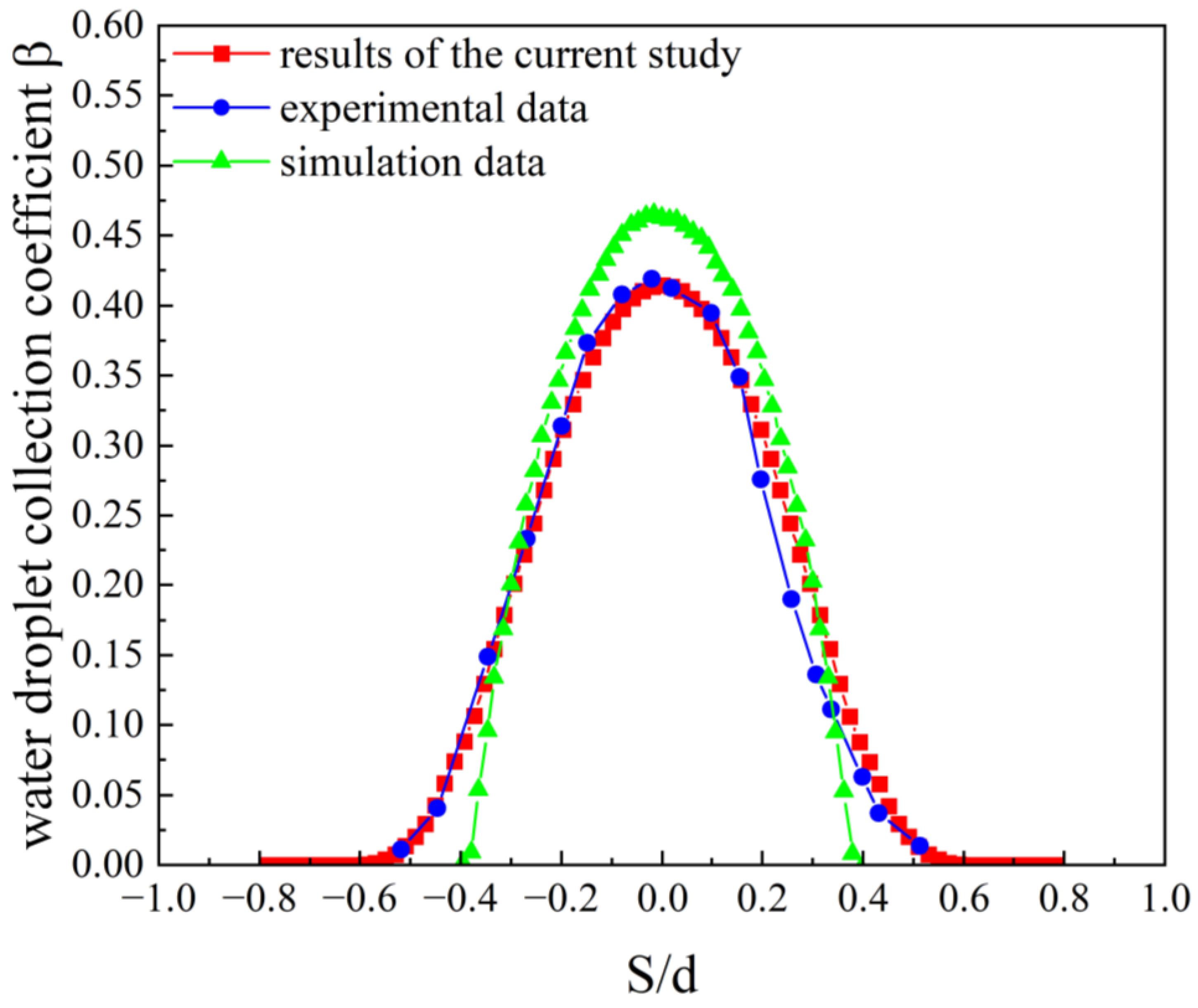
2.4. Verification of the Calculation Method

Experimental measurement of the water droplet collection coefficient is limited by the properties of fluid, so there are few previous experiments to measure the water droplet collection coefficient in simple geometric models. That was also one of the purposes of the numerical simulation study of droplet collection in the rotating spinners.
To verify the accuracy of the calculation, we compared our simulation results with experimental and simulation data [32,33] in the cylinder model, as shown in Figure 1. The data show that the maximum collection coefficient is at the front of the windward surface of the cylinder, and it gradually decreases along the direction of inflow velocity. S is the arc length from the most upstream point to a position along the surface of the cylinder, and d is the diameter of cylinder. The reason for the difference between the simulated data and experimental data is that all droplet diameters were not the same in the experiment, and the single diameter hypothesis in the simulation was not satisfied. However, the droplet conforms to certain statistical rules. In this study, the Langmuir-D distribution [33] was used to correct the simulation results. After comparison of the droplet collection coefficient along the cylinder, our calculation results were shown to be in good agreement with the experimental data, and the mean deviation was less than 6.9%.

3. Calculation Model and Working Condition

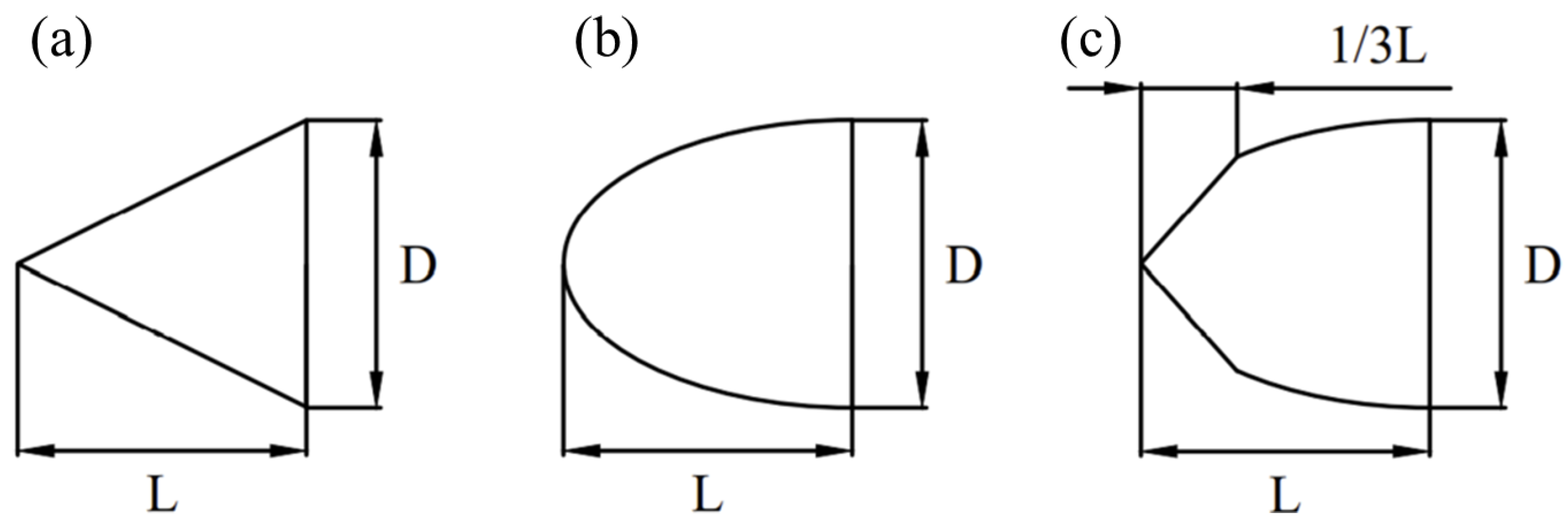
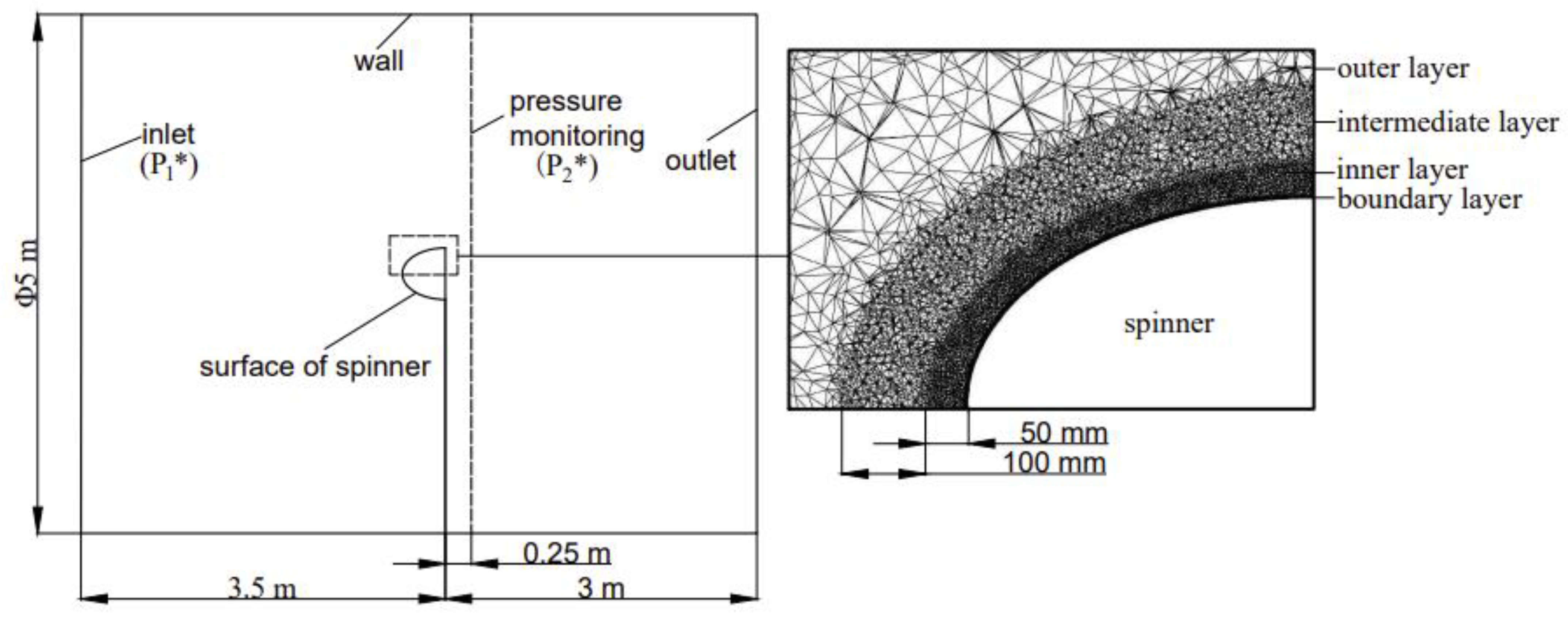
3.1. Geometric Modeling and Meshing

The three most commonly used shapes of an aero-engine spinner, including conical, elliptical, and coniptical shapes [19], were investigated in the study, as shown in Figure 2. Each kind of spinner has the same bottom diameter (D), which is 0.5 m, and three different lengths (L). The length of the conical part of the coniptical-shaped spinner is 1/3 L. As listed in Table 1, D/L = 1, 1.2 and 1.67. The range of D/L is determined with reference to the experimental data range of Hu et al. [18].
For all the spinner models, the calculation area is a cylindrical area with a length of 6.5 m and a diameter of 5m. According to the distance from the spinner surface, the calculation area is divided into four mesh zones: outer layer zone, intermediate layer zone, inner layer zone, and boundary layer zone. The mesh density increases successively towards the spinner surface, and the computational model is meshed by unstructured grids, as shown in Figure 3. The geometric dimensions and cell numbers of each model are also shown in Table 1.

3.2. Working Condition

To explore the trends of water collection characteristics of the three kinds of spinner, the inflow velocity and diameter to length ratio (D/L) were changed from 80 m/s to 200 m/s, and from 1 to 1.67, respectively. The rotation speed of the spinner was 8000 r/min, and the Liquid Water Content (LWC) was 1.5 g/m3. The Medium Volume Diameter (MVD) of the water droplet was 16μm. The inflow velocities used in the model are shown in Table 1. Eighteen groups of examples were calculated in the study. The inflow parameters were selected based on actual flight conditions of civil aircraft and the range of ice accumulation parameters were provided by icing wind tunnel data [10,18]. In our study, since the water droplet size of 16μm was small, and no account was taken of droplet rebound and splash phenomena, the water droplets were assumed to stick to the spinner surface after droplet impact.

4. Results and Analysis

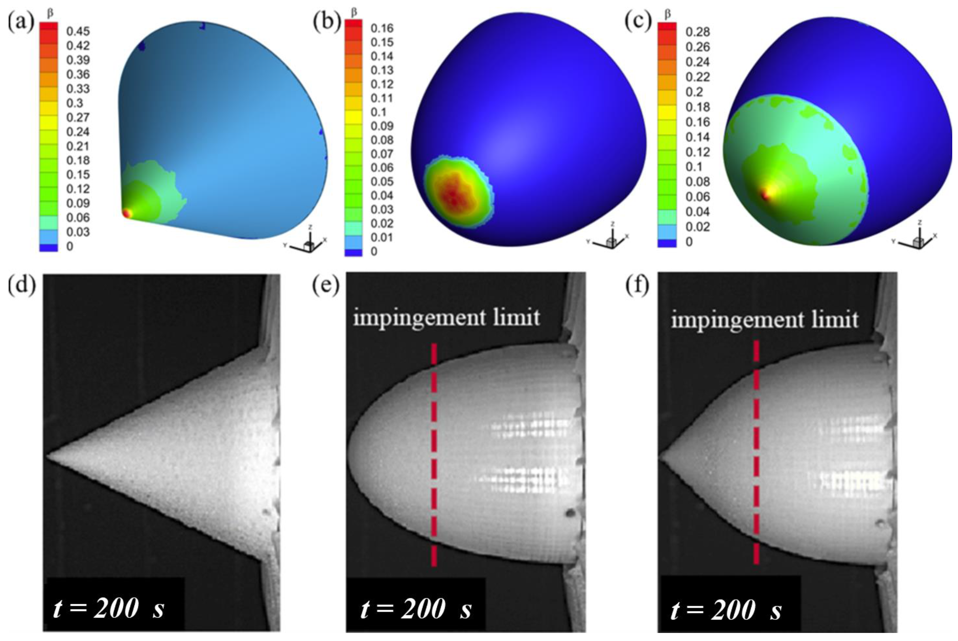
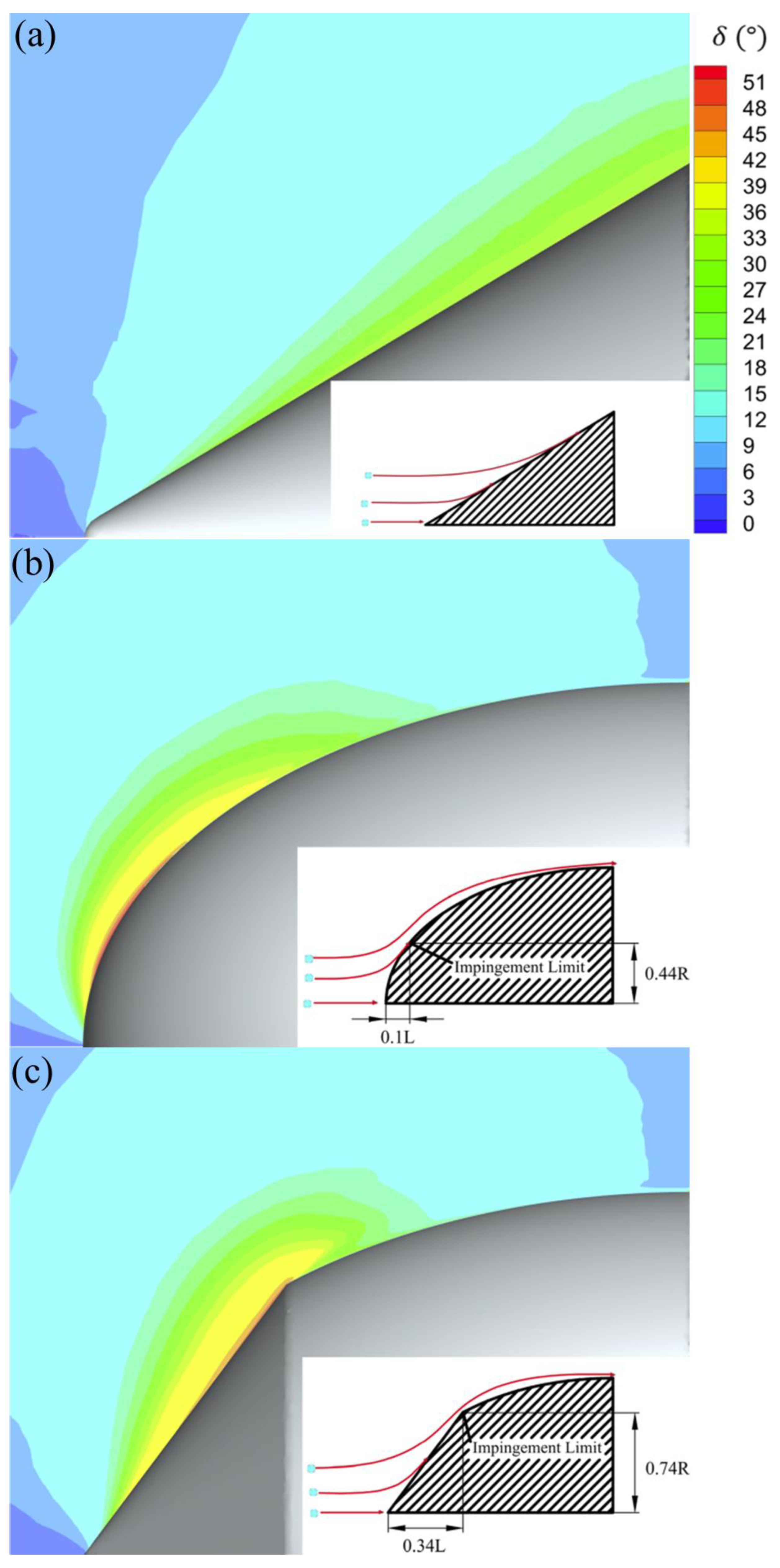
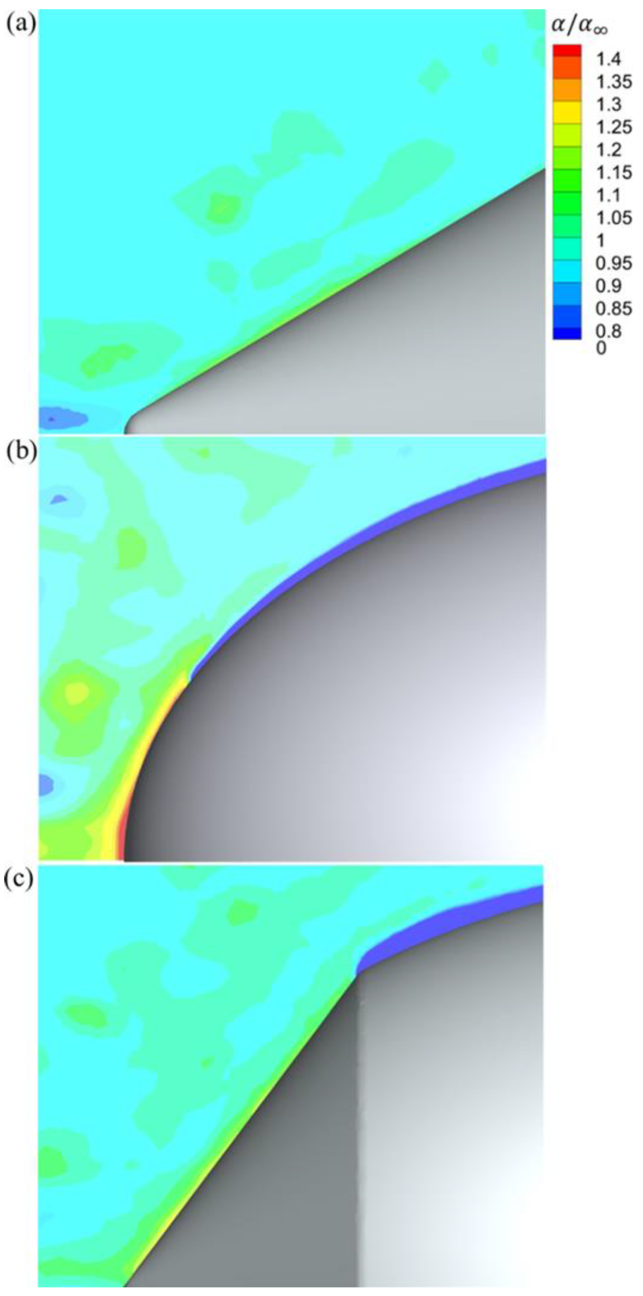
4.1. Effect of Spinner Shape on Droplet Impact Characteristics

In this section, the effect of spinner shape on droplet impact characteristics is discussed, as well as exploration of the mechanism of the dynamic ice accretion process in the experiments [17] (see Figure 4). Three geometric models were selected with different spinner shapes, and the inflow velocity was maintained at 80 m/s and D/L = 1.2 (1, 5, and 9 in Table 1). The distributions of water droplet collection coefficients β on the three types of spinner surfaces are shown in Figure 4a–c. The results indicate that the impact area covered all the windward surface on the conical-shaped spinner. However, the impact area only covered the front part of the windward surface on the elliptical-shaped spinner and the windward surface of the conical region on the coniptical-shaped spinner.
Here, the impingement limit was defined as the position where the water droplet collection coefficient becomes zero. At the downstream of the impingement limit, no droplets land on the rotating surface. In the icing experiment, the impingement limit was the most upstream position where no icing occurs (see Figure 4e,f). The simulation results are consistent with the characteristics of the icing distribution and the position of the impingement limit observed in the experiments of Li et al. [17].
Figure 5 shows the variation of the water droplet collection coefficient along the dimensionless radius (r/R, R is the bottom radius of the spinner) on the Y = 0 plane. For all spinner shapes, the maximum collection coefficient was located on the top point of the spinner surface and decreased continuously along the direction of air flow. The influences of spinner shape on the local water droplet collection coefficient were different. Surrounding the top point, the water droplet collection coefficient of the conical-shaped spinner was highest, followed by the coniptical-shaped spinner and the elliptical-shaped spinner. There was no impingement limit on the surface of the conical-shaped spinner. Once reaching the impingement limit, water droplet collection coefficient decayed to zero on the surfaces of coniptical-shaped spinner and the elliptical-shaped spinner. However, the impingement limit of the elliptical shape occurred at r/R~0.35, while that of coniptical shape appeared at r/R~0.75.
The results show that on the droplet-covered surface, the elliptical shape had the smallest mass flow rate of water collection at 0.292 g/s. Mass flow rates of water collection were 0.329 g/s and 0.739 g/s on the conical-shaped spinner and the coniptical-shaped spinner, respectively. Thus, water droplet collection was considerably different on the three spinner shapes, which is further analyzed in the following section.

4.2. Difference Analysis of Droplet Impact Characteristics of Three Spinners

Force analysis of a single droplet was carried out in a stationary coordinate system to analyze the influence mechanism of spinner shape on water collection characteristics. According to Newton’s second law, the equation of motion of a single water droplet is expressed as:
m w V t = 1 2 ρ a A C d V a V V a V
The mass of a single droplet with the diameter of d , m w , is given by:
m w = 1 6 π ρ d 3
The windward area of water droplets A is expressed as:
A = 1 4 π d 2
Substituting Equations (10), (11), (5) and (6) into Equation (9), we get:
V t = 3 4 μ a ρ d 2 C d R e V a V
At the front of spinner shape there is a point O on the center line of the spinner (see Figure 6), while on the spinner surfaces there is a point A ( A 1 , A 2 , o r A 3 ) with the distance of r to the center line. The origin of the coordinate axis is located at the stationary point of the spinner. The angle θ is defined as the angle between the center line and the line of O A . The angle between the motion direction of the water droplet and the axial direction is defined as δ. As shown in Figure 6, the windward area of the three types of spinner shapes has different distributions along the axial position, and the angle θ increases from the conical shape, to the coniptical shape to elliptical shape. The change of the angle θ that forms at the front of the spinner shape leads to differences in axial deceleration and radial acceleration regions, and further influences the force of droplets.
Based on Equation (12), the aerodynamic force is positively related to the velocity difference between water droplets and air. The more dramatic the change in air velocity, the greater the force on the water droplets. Since air always tends to flow parallel to the wall, a larger θ results in a larger velocity gradient. As a result, the axial and radial aerodynamic forces of water droplets are influenced by spinner shape.
When the inflow velocity was 120 m/s (No. 2, 6 and 10 in Table 1), the air velocity and aerodynamic force in front of spinners were compared at distances of r / R = 0 and r / R = 0.4 , as in Figure 7 and Figure 8.
Since the spinner shape is symmetric, the water droplets move along the center line only, with an axial velocity of u a . Figure 7a shows the axial velocity of air along the center line with r / R = 0 . At x / D = 1.5 ,   u a is not influenced by spinner shape. As the droplet approaches the spinner surface along the center line, u a first decreases slowly and then decreases quickly to zero for all the spinner shapes. For the conical shape, the rapid decrease of u a begins at the location of x / D = 0.1 , while for elliptical shape and coniptical shape x / D ~ 0.3 . Thus, the spinner shape would change the local velocity of air in the front of the spinners. As a result, the axial force acting on the water droplet F a x i a l shows different trend lines for the three spinner shapes (see Figure 7b): F a x i a l of droplets in the elliptical spinner is increases quickly, followed by the coniptical and conical spinners. As the droplet approaches the surface, the change rate of F a x i a l is highest for the conical shape.
Except for the center line, water droplets move towards the spinner shape with the angle δ between the motion direction of water droplets and the axial direction. Under the aerodynamic force, the motion of droplets is influenced by the velocity of the local air. The velocity of the local air has two velocity components: the axial velocity u a , and the radial velocity v a . Figure 8 shows the change of u a and v a at r / R = 0.4 , as well as F a x i a l (axial force acting on droplets) and F r a d i a l (radical force acting on droplets).
For the three spinner shapes, u a continuously decreases towards the spinner surface while v a increases, but the velocity gradients of u a and v a are influenced by the spinner shape. Figure 8b,d shows the trend lines of F a x i a l and F r a d i a l . As the droplets approach the surface, both F a x i a l and F r a d i a l first increase and then decrease. The maximum F a x i a l and F r a d i a l occur on the elliptical shape, followed by the coniptical and conical spinners, which can be explained by the detailed change of the angle δ towards to the spinner surface.
Figure 9 shows the distribution of the angle δ between the motion direction of the water droplet and the axial direction. Along the conical spinner surface, δ continuously increases, but δ is always smaller than the half angle of the cone (~31 °), so droplets impact on the whole spinner surface, even in the rear of the spinner (see Figure 10a). Similar phenomena occur on the conical segment of the coniptical spinner. Initially, the impingement limit, δ , along elliptical spinner surface is smaller than the angle between the local tangent line and axial direction. In contrast, after passing through the impingement limit (see elliptical spinner and the elliptical segment of the coniptical spinner in Figure 9b,c), δ of the local droplet velocity is larger than the angle between the local tangent line and axial direction, so no droplets land on the surface (see Figure 10b,c). The conical segment guides water droplets to move parallel to the surface, while the elliptical segment causes water droplets to move away from the wall.
The δ distribution of water droplets is consistent with the law obtained from the experimental data measured by PIV [17]. Both showed that the impact of water droplets occurs at different ranges on spinner surfaces of different shape.
Figure 10 shows the distribution of the ratio of the local water volume fraction ( α ) to the water volume fraction at the inlet ( α ) for the three types of spinners. In the front of the spinner, α / α is highest on the elliptical spinner surface, followed by the coniptical spinner surface and conical spinner surface. The stronger the deceleration effect ( V / t ), the greater the force to prompt the local droplets to adjust direction of motion. Once the motion direction of droplets δ is smaller than the angle between the local tangent line and axial direction, the droplets impact the spinner surface.
The total mass flow rate of water collection W ˙ was 0.984 g/s on the elliptical shape, which was lowest among the three spinner shapes. Mass flow rates of water collection were 1.033 g/s and 2.053 g/s on the conical-shaped spinner and the coniptical-shaped spinner, respectively. Therefore, the spinner shape significantly affects the local air flow and the force acting on the local droplet, further changing the motion direction and the local collection of water droplets.

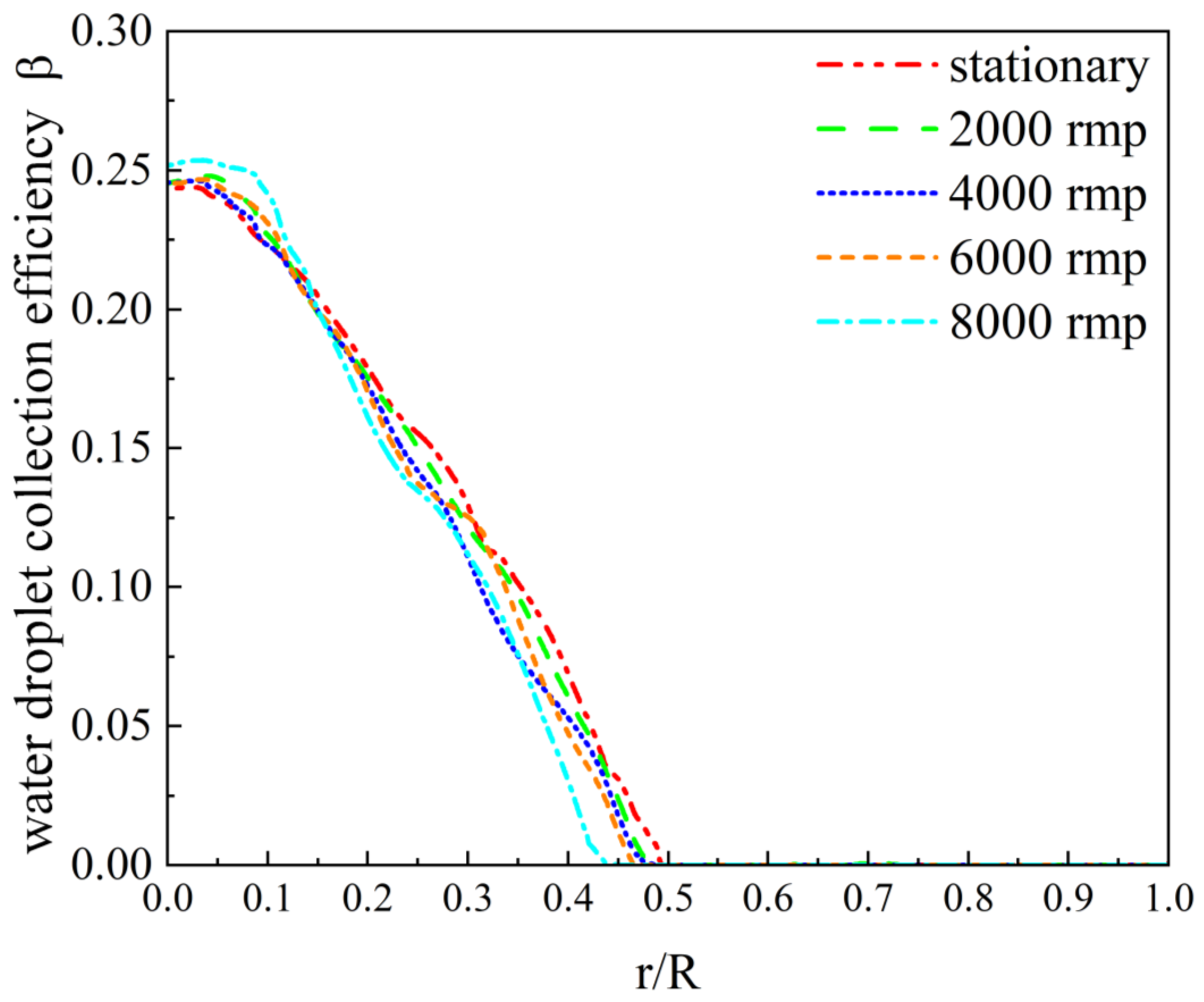
4.3. Effect of Rotational Speed on Droplet Impact Characteristics

In the range of the rotational speed of the spinner from 0 to 8000 rpm, the effect of rotational speed on droplet impact characteristics was analyzed on the elliptical spinner. The inflow velocity was maintained at 120 m/s and D/L = 1.2 (see No. 6 in Table 1). Figure 11 shows the influence of rotational speed on water droplet collection efficiency β. The trend lines of β are similar at different rotational speeds. However, the high rotational speed slightly shortens the distance from the stagnation point to the impingement limit. The position of the impingement limit r⁄R was 0.5 on the stationary surface, while r⁄R was 0.44 at the rotational speed of 8000 rpm. Similar phenomena are described in the literature [15,16].
The influence of rotational speed on the spinner was further analyzed from the aspect of forces acting on the droplets. In a rotating coordinate system, the governing equation of elemental volume is expressed by Equation (2), and the influence of centrifugal force F e and Coriolis force F c on the motion of droplets is shown in Figure 12. The axial velocity independent of the Coriolis and centrifugal forces is ignored in the discussion.
Three conditions are included in the force analysis of the elemental volume of droplets. First, the motion of droplets that are far away from the spinner surface are not affected by the spinner shape. In the rotating coordinate system, the droplets move in a uniform circle. The direction of the centrifugal force is opposite to the Coriolis force, and F e = 1 2 F c . The combined force of F e and F c provides the centripetal acceleration.
When close to the boundary layer, the motion of droplets is affected by the spinner shape. There is an angle δ between the motion direction of the water droplet and the axial direction, so the vertical velocity component of droplets is v y . In addition to the radial Coriolis force F c r , the circumferential Coriolis force F θ r = 2 ω v y promotes the increase of circumferential velocity. In a state of force balance, rotational speed would not change the impact characteristics.
In the boundary layer, enhanced viscous force considerably reduces circumferential velocity, so the force balance cannot be maintained, forcing the droplet to move centrifugally. This effect is aggravated with an increase of rotational speed. Since the thickness of the boundary layer is very thin, the rotational speed only has a slight effect on the water droplet collection coefficient, which is not considered in the following discussion. Our conclusions are made based on a rotationally symmetric surface. For rotating blades, the influence of rotational speed must be considered.

4.4. Effect of Inflow Velocity on Droplet Impact Characteristics

In the range of inflow velocities from 80 m/s to 200 m/s, the effect of inflow velocity on droplet impact characteristics on the three spinner shapes was investigated (1–12 in Table 1), as shown in Figure 13. Figure 13a shows variations of the water droplet collection coefficient β at different inflow velocities on the conical spinner. As the inflow velocity increases, the water droplet collection coefficients on the whole windward surface increase correspondingly.
Figure 13b shows the variation of β at different inflow velocities on the elliptical spinner. With the increase of velocity, not only the local water droplet collection coefficient increases sharply, but more windward surfaces are impacted by the water droplets, resulting in the axial extension of the impingement limit. Similar rules on spinner and engine air intake were obtained by simulation [9,27] and icing wind tunnel experiments [9] of other researchers.
Figure 13c shows the variation of β at different inflow velocities on the coniptical spinner. The increase of inflow velocity results in a larger local β in the conical segment of the coniptical spinner, but does not affect the position of impingement limit of the coniptical spinner.
Effect of inflow velocity on the total mass flow rate of water collection W ˙ is shown in Figure 14. At an inflow velocity of 80 m/s, W ˙ of the elliptical spinner (~0.292 g/s) is the lowest among three spinner shapes. As the inflow velocity increased to 160 m/s and 200 m/s, W ˙ of the conical spinner was the lowest while that of the coniptical spinner was still the highest. With the increase of inflow velocity, the water collection of the elliptical spinner surpassed that of the conical spinner. The reason is that the higher inflow velocity leads to a higher water droplet collection coefficient β, and axial extension of the impingement limit on the elliptical spinner. In other words, water collection on the elliptical spinner is more sensitive to the inflow velocity than in the other two spinners.

4.5. Effect of Diameter to Length Ratio on Droplet Impact Characteristics

Effect of diameter to length ratio (D/L) on droplet impact characteristics was analyzed at the inflow velocity of 80 m/s, and D/L = 1, 1.2 and 1.67 (see 1, 5, 9, and 13 to 18 in Table 1). Figure 15 shows the influence of D/L on water droplet collection efficiency β on the conical spinner and the elliptical spinner. At the stagnation point, the greater the diameter to length ratio D/L, the lower β on the conical spinner and the elliptical spinner. At the rear of the spinner surface of the conical spinner, and close to the impingement limit on the elliptical spinner, the influence of D/L on β is opposite: the greater diameter to length ratio D/L, the higher β . On the elliptical spinner, the diameter to length ratio D/L also affects the position of the impingement limit, and the higher D/L tends to extend the impingement limit.
Figure 16 shows the influence of the diameter to length ratio D/L on the total mass flow rate of water collection W ˙ . Interestingly, with the increase of D/L, W ˙ increased on the conical-shaped spinner and the coniptical-shaped spinner, but decreased on the elliptical-shaped spinner. When D/L = 1 to 1.67, W ˙ decreased from 0.306 g/s to 0.205 g/s on the elliptical spinner. Although the higher D/L slightly extends the droplet-covered windward surface on the elliptical spinner, water droplet collection efficiency β considerably decreases, and hence the total mass flow rate of water collection W ˙ also decreases.

4.6. Comparison of Aerodynamic Characteristics

The improvement of the aerodynamic performance is desirable for the design of an aero-engine spinner. In our study, the effects of spinner shape on pressure loss and uniformity of pressure distribution were considered. To quantitatively compare the pressure loss through the spinner, the total pressure loss coefficient C p was defined as:
C p = P 1 * P 2 * 1 2 ρ v 2
Here, P 1 * is the total pressure of the inflow, P 2 * is the total pressure of the pressure at the downstream of the spinner surface (see Figure 3), and 1 2 ρ v 2 represents the dynamic pressure of the inflow. A location 25 cm behind the spinner (~half of the chord length of the fan blade) was selected for monitoring the change of P 2 * , showing the aerodynamic condition of the fluid flowing through the spinner.
Figure 17 shows the profile of the total pressure loss coefficient C p along the radial axis for the three spinner shapes ( 1 r / R 2 ). The inflow velocity was maintained at 80 m/s and D/L=1.2 (No. 1, 5, 9 in Table 1). The trend lines of C p through the elliptical spinner and the coniptical spinner were similar: the maximum C p was ~0.8 and the area of pressure loss was within r / R 1.4 . The trend line of C p through the conical spinner was above the lines of the other two types of spinners. The maximum value of C p was 1.45 and the area of pressure loss was within r / R 1.6 .
At the rear part of the spinners, the surface of the conical spinner still maintained a large angle with the axial direction, which caused the air to flow parallel to the wall and form a large area with low pressure after passing through the spinner. In contrast, in spinners with elliptical region guides, the air flows gradually parallel to the axial direction. This is consistent with the assertion of Linke-Diesinger [19], that elliptical spinners have better aerodynamic performance

5. Conclusions

Droplet impact characteristics on conical-shaped, coniptical-shaped, and elliptical-shaped aero-engine spinners were numerically investigated.
The spinner shape significantly affected the local air flow and the force acting on the local droplet, changing the motion direction and the local collection of water droplets, leading to different water collection characteristics.
(1)
The droplets impacted on the entire conical spinner surface, the front segment of the elliptical spinner, but only the conical segment of coniptical spinner.
(2)
The conical spinner had the smallest mass flow rate of water collection among the three spinners at high inflow velocities greater than 160 m/s, while the elliptical spinner had the smallest mass flow rate of water collection at low inflow velocities below 120 m/s.
(3)
With increasing diameter to length ratio D/L, W ˙ increased for the conical spinner, but decreased for the elliptical spinner.
(4)
Air pressure loss through the conical spinner was the largest and uniformity was the lowest. The elliptical spinner had the smaller pressure loss and the best uniformity.
From an anti-ice point of view, the conical spinner was most suitable for a spinner with small conical angle at high inflow velocity, and the elliptical spinner was most suitable for a design with a low eccentricity profile and low-speed flight.

Author Contributions

Conceptualization, X.G., Z.W.; methodology, X.G., B.Q.; software and simulation, B.Q.; formal analysis, B.Q.; writing—original draft preparation, X.G., B.Q.; writing—review and editing, X.G., Z.W.; supervision, H.L.; project administration, H.L.; funding acquisition, X.G.; H.L. All authors have read and agreed to the published version of the manuscript.

Funding

This work was supported by the National Natural Science Foundation of China (No. 52206066).

Institutional Review Board Statement

Not applicable.

Informed Consent Statement

Not applicable.

Data Availability Statement

Not applicable.

Conflicts of Interest

The authors declare no conflict of interest.

References

  1. Cao, Y.; Tan, W.; Wu, Z. Aircraft icing: An ongoing threat to aviation safety. Aerosp. Sci. Technol. 2018, 75, 353–385. [Google Scholar] [CrossRef]
  2. Venkataramani, K.; McVey, L.; Holm, R.; Montgomery, K. Inclement weather considerations for aircraft engines. In Proceedings of the 45th AIAA Aerospace Sciences Meeting and Exhibit, Reno, NV, USA, 8–11 January 2007; p. 695. [Google Scholar]
  3. Veres, J.P.; Jorgenson, P.C.E. Modeling commercial turbofan engine icing risk with ice crystal ingestion. In Proceedings of the 5st AIAA Atmospheric and Space Environments Conference, San Diego, CA, USA, 24–27 June 2013; p. 2679. [Google Scholar]
  4. Al-Khalil, K.M.; Keith, T.G.; De Witt, K.J. Icing calculations on a typical commercial jet engine inlet nacelle. J. Aircr. 1997, 34, 87–93. [Google Scholar] [CrossRef]
  5. Li, L.; Liu, Y.; Tian, L.; Hu, H.; Hu, H.; Liu, X.; Hogate, I.; Kohli, A. An experimental study on a hot-air-based anti-/de-icing system for aero-engine inlet guide vanes. Appl. Therm. Eng. 2020, 167, 114778. [Google Scholar] [CrossRef]
  6. Jung, S.; Raj, L.P.; Rahimi, A.; Jeong, H.; Myong, R.S. Performance evaluation of electrothermal anti-icing systems for a rotorcraft engine air intake using a meta model. Aerosp. Sci. Technol. 2020, 106, 106174. [Google Scholar] [CrossRef]
  7. Gutiérrez, B.A.; Della Noce, A.; Gallia, M.; Bellosta, T.; Guardone, A. Numerical simulation of a thermal Ice Protection System including state-of-the-art liquid film model. J. Comput. Appl. Math. 2021, 391, 113455. [Google Scholar]
  8. Lian, W.; Xuan, Y. Experimental investigation on a novel aero-engine nose cone anti-icing system. Appl. Therm. Eng. 2017, 121, 1011–1021. [Google Scholar] [CrossRef]
  9. Ahn, G.B.; Jung, K.Y.; Myong, R.S. Numerical and experimental investigation of ice accretion on rotorcraft engine air intake. J. Aircr. 2015, 52, 903–909. [Google Scholar] [CrossRef] [Green Version]
  10. Dong, W.; Zheng, M.; Zhu, J.; Lei, G.; Zhao, Q. Experimental investigation on anti-icing performance of an engine inlet strut. J. Propul. Power 2017, 33, 379–386. [Google Scholar] [CrossRef]
  11. Kreeger, R.E.; Douglass, R.; Gazella, M.; Koster, Z.; Turk, J.; Work, A.H. Analysis and prediction of ice shedding for a full-scale heated tail rotor. In Proceedings of the 8th AIAA Atmospheric and Space Environments Conference, Washington, DC, USA, 13–17 June 2016; p. 3443. [Google Scholar]
  12. Li, Y.; Sun, C.; Jiang, Y.; Feng, F. Scaling Method of the Rotating Blade of a Wind Turbine for a Rime Ice Wind Tunnel Test. Energies 2019, 12, 627. [Google Scholar] [CrossRef] [Green Version]
  13. Bidwell, C.S. Particle Trajectory and Icing Analysis of the E (sup 3) Turbofan Engine Using LEWICE3D Version 3. In Proceedings of the International Conference on Aircraft and Engine Icing and Ground Deicing, Chicago, IL, USA, 13–17 June 2011; NASA Glenn Research Center: Cleveland, OH, USA, 2011. No. NASA/TM-2012-217696. [Google Scholar]
  14. Li, L.; Liu, Y.; Hu, H. An Experimental Study of the Dynamic Ice Accreting Process over a Rotating Aero-engine Fan Model. In Proceedings of the Atmospheric and Space Environments Conference, Atlanta, GA, USA, 25–29 June 2018; p. 3013. [Google Scholar]
  15. Zheng, M.; Guo, Z.; Dong, W.; Guo, X. Experimental investigation on ice accretion on a rotating aero-engine spinner with hydrophobic coating. Int. J. Heat Mass Transf. 2019, 136, 404–414. [Google Scholar] [CrossRef]
  16. Mu, Z.; Lin, G.; Bai, L.; Shen, X.; Bu, X. 3D Numerical Simulation of Ice Accretion on a Rotating Surface. Int. J. Aeronaut Space 2017, 18, 352–364. [Google Scholar] [CrossRef]
  17. Li, L.; Liu, Y.; Hu, H. An experimental study on dynamic ice accretion process over the surfaces of rotating aero-engine spinners. Exp. Therm. Fluid Sci. 2019, 109, 109879. [Google Scholar] [CrossRef]
  18. Hu, Y.P.; Ji, H.H.; Wang, J.; Chen, N.L.; Cao, G.Z.; Tong, H.; Pang, L. Experiment on effect of cone angle on ice accretion of rotating spinner. J. Aerosp. Power 2014, 29, 495–503. [Google Scholar]
  19. Linke-Diesinger, A. Systems of Commercial Turbofan Engines: An Introduction to Systems Functions; Springer Science & Business Media: Berlin/Heidelberg, Germany, 2008. [Google Scholar]
  20. Shen, X.; Tan, Y.; Yu, R.; Liu, X.; Lin, G.; Xu, Z.; Guo, Y. Effects of upstream component and air injection on water droplet impingement characteristics for downstream surfaces. Int. J. Aerosp. Eng. 2021, 2021, 2698028. [Google Scholar] [CrossRef]
  21. Wang, D.; Sun, M.; Ma, R.; Shen, X. Numerical Modeling of Ice Accumulation on Three-Dimensional Bridge Cables under Freezing Rain and Natural Wind Conditions. Symmetry 2022, 14, 396. [Google Scholar] [CrossRef]
  22. Feng, K.; Lu, Z.; Yun, W. Aircraft icing severity analysis considering three uncertainty types. AIAA. J. 2019, 57, 1514–1522. [Google Scholar] [CrossRef]
  23. Tong, X.; Luke, E. Eulerian simulations of icing collection efficiency using a singularity diffusion model. In Proceedings of the 43rd AIAA Aerospace Sciences Meeting and Exhibit, Reno, NV, USA, 10–13 January 2005. [Google Scholar]
  24. Shen, X.; Zhao, W.; Qi, Z.; Lin, G.; Wang, L. Analysis of Numerical Methods for Droplet Impingement Characteristics under Aircraft Icing Conditions. Aerospace 2022, 9, 416. [Google Scholar] [CrossRef]
  25. Cao, Y.; Xin, M. Numerical simulation of supercooled large droplet icing phenomenon: A Review. Arch. Comput. Methods Eng. 2019, 27, 1231–1265. [Google Scholar] [CrossRef]
  26. Shen, X.; Zhang, Z.; Lin, G.; Mu, Z.; Bu, X. Droplet impingement calculation on complex surface of rotating part. Acta Aerodyn. Sin. 2016, 34, 709–713. [Google Scholar]
  27. Wu, M.; Chang, S.; Leng, M.; Wang, C. Simulation of droplet impingement characteristics of spinner based on Eulerian method. J. Beijing Univ. Aeronaut. Astronaut. 2014, 40, 1263. [Google Scholar]
  28. Xie, L.; Li, P.; Chen, H.; Liu, H. Robust and efficient prediction of the collection efficiency in icing accretion simulation for 3D complex geometries using the Lagrangian approach I: An adaptive interpolation method based on the restricted radial basis functions. Int. J. Heat Mass Transf. 2020, 150, 119290. [Google Scholar] [CrossRef]
  29. Lavoie, P.; Radenac, E.; Blanchard, G.; Laurendeau, E.; Villedieu, P. Penalization Method for Eulerian Droplet Impingement Simulations Toward Icing Applications. AIAA. J. 2022, 60, 641–653. [Google Scholar] [CrossRef]
  30. Han, H.; Yin, Z.; Ning, Y.; Liu, H. Development of a 3D Eulerian/Lagrangian Aircraft Icing Simulation Solver Based on OpenFOAM. Entropy 2022, 24, 1365. [Google Scholar] [CrossRef]
  31. Ansys Inc. Ansys FLUENT User’s Guide, Software Package; Version 19.1; Ansys Inc.: Pune, India, 2019. [Google Scholar]
  32. Armand, C. Techniques and Facilities Used at the OneraModane Centre for Icing Tests; AGARD-AF-127; North Atlantic Treaty Organization Advisory Group for Aerospace Research and Development: Neuilly sur Seine, France, 1978. [Google Scholar]
  33. Boutanios, Z.; Bourgault, Y.; Habashi, W.; Issac, G.; Cober, S. 3D droplets impingement analysis around an aircraft’s nose and cockpit using FENSAP-ICE. In Proceedings of the 36th AIAA Aerospace Sciences Meeting and Exhibit, Reno, NV, USA, 6–9 January 1998; p. 200. [Google Scholar]
Figure 1. Verification of the calculation method by comparing simulation results with experimental data [32] and simulation data [33].
Aerospace 10 00068 g001
Figure 2. Schematic of three shapes of spinner models: (a) conical shape; (b) elliptical shape; (c) coniptical shape.
Aerospace 10 00068 g002
Figure 3. Schematic of mesh division with four mesh zones.
Aerospace 10 00068 g003
Figure 4. Water droplet collection coefficient β on three types of spinners: (a) conical-shaped spinner; (b) elliptical-shaped spinner; (c) coniptical-shaped spinner. Ice over the surfaces of three types of spinners under the rime icing condition [17] (df).
Aerospace 10 00068 g004
Figure 5. Variation of the water droplet collection coefficient of the three spinners.
Aerospace 10 00068 g005
Figure 6. Main difference between the three types of cap structure.
Aerospace 10 00068 g006
Figure 7. Aerodynamic force analysis of water droplets at r / R = 0 . (a) Axial velocity of air u a ; (b) axial force of water droplets F a x i a l .
Aerospace 10 00068 g007
Figure 8. Aerodynamic force analysis of water droplets at r / R = 0.4 . (a) Axial velocity of air u a ; (b) axial force of water droplets F a x i a l ; (c) radial velocity of air v a ; (d) radial force of water droplets F r a d i a l .
Aerospace 10 00068 g008
Figure 9. Distribution of the angle, δ , of water droplets: (a) conical spinner; (b) elliptical spinner; (c) coniptical spinner.
Aerospace 10 00068 g009
Figure 10. Distribution of the ratio of the local water volume fraction ( α ) to the water volume fraction at the inlet ( α ): (a) conical spinner; (b) elliptical spinner; (c) coniptical spinner.
Aerospace 10 00068 g010
Figure 11. Water droplet collection efficiency β with different rotational speeds on the elliptical spinner.
Aerospace 10 00068 g011
Figure 12. Force analysis of elemental volume. F e is the centrifugal force, F c r is the radial Coriolis force, F c θ is the circumferential Coriolis force.
Aerospace 10 00068 g012
Figure 13. Influence of inflow velocity on water droplet collection efficiency with varied spinner shapes: (a) conical spinner; (b) elliptical spinner; (c) coniptical spinner.
Aerospace 10 00068 g013
Figure 14. Comparison of water collection on three spinners with different inflow velocity.
Aerospace 10 00068 g014
Figure 15. Influence of D/L on water droplet collection efficiency: (a) elliptical spinner; (b) conical spinner.
Aerospace 10 00068 g015
Figure 16. Influence of D/L on the total mass flow rate of water collection W ˙ .
Aerospace 10 00068 g016
Figure 17. Total pressure loss coefficient C p behind the spinner.
Aerospace 10 00068 g017
Table 1. Model and working condition.
No.ShapeD/LInflow Velocity (m/s)Number of Cells
1conical1.28010.7 million
2conical1.212010.7 million
3conical1.216010.7 million
4conical1.220010.7 million
5elliptical1.28012.4 million
6elliptical1.212012.4 million
7elliptical1.216012.4 million
8elliptical1.220012.4 million
9coniptical1.28012.2 million
10coniptical1.212012.2 million
11coniptical1.216012.2 million
12coniptical1.220012.2 million
13conical18010.6 million
14elliptical18012.9 million
15coniptical18012.5 million
16conical1.67809.7 million
17elliptical1.678011.8 million
18coniptical1.678011.7 million
Disclaimer/Publisher’s Note: The statements, opinions and data contained in all publications are solely those of the individual author(s) and contributor(s) and not of MDPI and/or the editor(s). MDPI and/or the editor(s) disclaim responsibility for any injury to people or property resulting from any ideas, methods, instructions or products referred to in the content.

