Article

Design and Qualification of an Additively Manufactured Manifold for Aircraft Landing Gears Applications

1
Magnaghi Aeronautica of MA Group Company, Aeronautical Industry, via Galileo Ferraris 76, 80146 Napoli, Italy
2
Aidro S.r.l., 21020 Taino, Italy
*
Author to whom correspondence should be addressed.
Aerospace 2023, 10(1), 69; https://doi.org/10.3390/aerospace10010069
Submission received: 28 November 2022 / Revised: 27 December 2022 / Accepted: 5 January 2023 / Published: 10 January 2023
(This article belongs to the Special Issue Metal Additive Manufacturing for Aerospace Applications)

Abstract

:
The continuous pursuit of reducing weight and optimizing manufacturing processes is increasingly demanded in transportation vehicles, particularly in the aerospace field. In this context, additive manufacturing (AM) represents a well-known technique suitable for re-engineering traditional systems, minimizing the product’s weight/volume and print time. The present research activity allowed for the exploration of the feasibility to replicate a conventional hydraulic manifold already certified for defence application with a lightweight and more compact issue through typical stringent aeronautical qualification steps. Computational modelling with lab test efforts made it possible to assess the compliance of the device with airworthiness certification requirements, giving a special focus to the fulfilment of structural requirements. In particular, the fatigue life characterization is still a crucial point to be well investigated in aeronautical components dfAM (designed for additive manufacturing) to demonstrate the maturity of the technology in the certification scenario. The new AM-driven design offers a more than 40 per cent weight reduction.

1. Introduction

The current manufacturing philosophy is rapidly evolving towards the use of additive manufacturing (AM) techniques in various fields of metallurgy. AM actually allows for a major level of design freedom when compared to conventional manufacturing practices, such as subtractive machining and casting; consequently, the component geometry can be adjusted layer-by-layer, reducing material mass and improving functionality, within the same space envelope [1,2].

1.1. Additive Manufacturing in the Aerospace Sector

The considerable development of this technology today has been particularly prompted by the multiple functional and profitable chances in the aerospace business. There are a lot of extreme applications in such a field including liquid-based fuel rocket engines, oleo-dynamic valves, propellant reservoirs, satellite parts, heat exchangers, and turbomachinery [3,4]. Blakey-Milner, B. et al. provide, in [5], a comprehensive review of numerous successful examples of metal AM applications in the aerospace field, with a detailed focus on the current state of the art and associated challenges. Most metal AM applications in aerospace are steered towards significant advantages for reducing cost and schedule time, as well as weight reduction and geometry simplification from previous designs [6]. However, the real economic savings can be measured only in the long term. Many open issues regard process maturity issues, combined also with high non-recurrent costs and expertise gained [7,8,9]. Currently, the AM process is still based on prototype and experimental lines for which the production rates are not yet so high as to be able to guarantee a favourable profit margin in the whole supply chain. Several key AM technologies are applied with DED (directed energy deposition) and LPBF (Laser Powder Bed Fusion) processes. The first category is preferred for larger volumes or for repairing existing components [10,11,12,13,14,15,16,17]. LPBF is nevertheless the most widely used for aerospace applications where high density or shape complexity are required [18,19,20,21]. The AM-based production of metal parts, although in rapid growth, has many points still to be consolidated, especially in terms of certification processes, quality control methods, and the repeatability of thermo-mechanical properties. In the case of the aerospace sector, test and qualification protocols are being developed by the main government entities such as the EASA (European Union Aviation Safety Agency), NASA (National Aeronautics and Space Administration), ESA (European Space Agency), and the FAA (Federal Aviation Administration) [22]. The definition of a well-recognized qualification process is identified as a possible factor that could accelerate a reliable adoption of AM to a great extent in the aerospace industry [10,23,24]. Structural integrity is among the vital aspects for mission-critical aerospace applications, particularly if considering the cyclic and impact loads. If on the one hand, actually, a quite mature level of confidence has been reached in the characterization of the static behaviour of metal alloys destined for AM technology (even better than standard specimens [25,26,27,28]), there is still an uncertainty regarding the fatigue and creep mechanical properties [29]. The samples forged as per AM tend to have a high percentage of porosity and surface roughness representing a source of premature fatigue damage (both HCF and LCF) [10,30]. Such superficial flaws can reduce the material ductility and introduce residual surface stresses capable of triggering potential cracks [31,32,33,34]. However, many advances have been made in mitigating these manufacturing imperfections: special processes such as heat treatments and HIP (hot isostatic pressing) can certainly improve these issues [35,36].

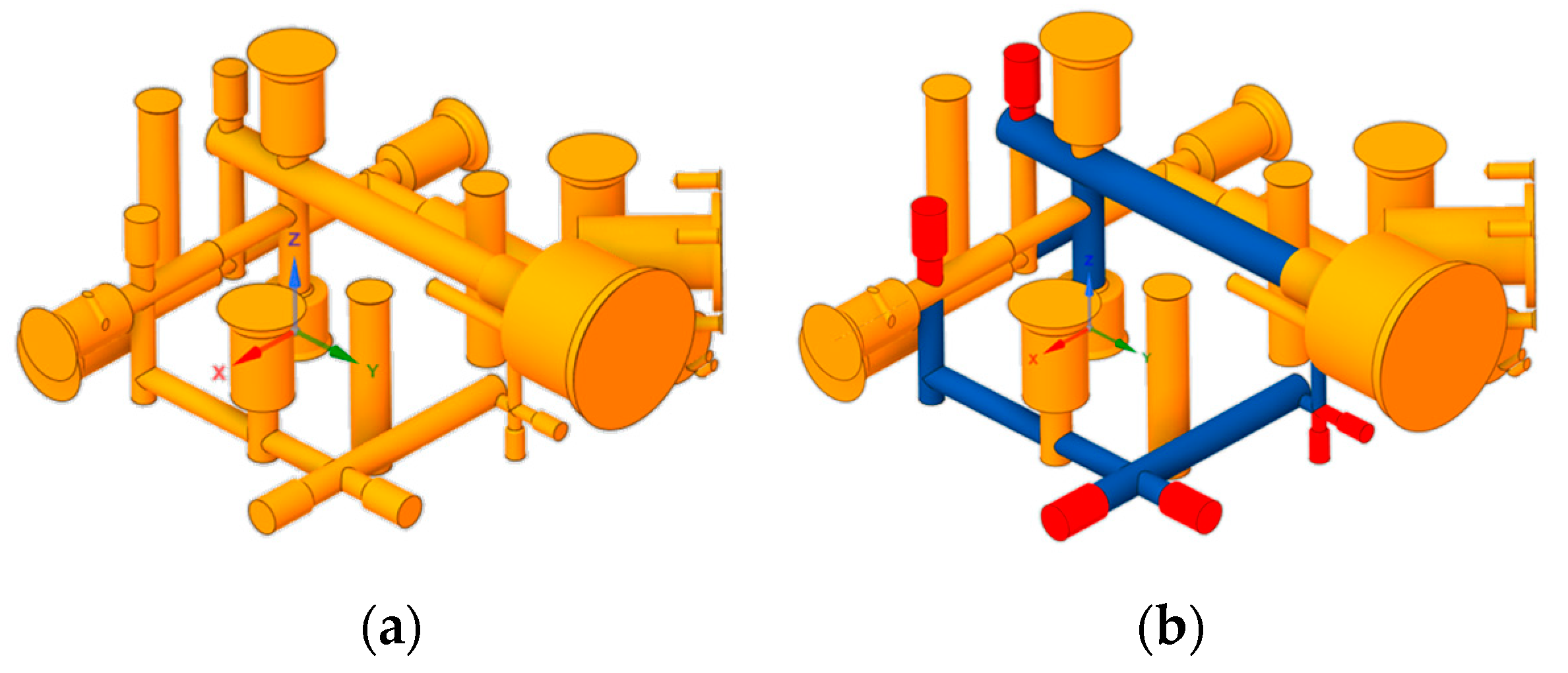
1.2. Hydraulic Equipment Designed for Additive Manufacturing

AM capabilities are generally better suited for the realization of small batches of highly customized products; strictly speaking in the aerospace framework, AM is really advantageous for metallic applications where a high level of geometry complexity occurs. Hydraulic manifolds can be considered attractive candidates for these novel optimization processes [37]. Such components are used to manage the flow communications among pumps, valves, and actuators in an oleo-dynamic circuit; it is manufactured starting from a stainless steel or aluminium alloy billet. The flow internal pathways are then finished by drilling processes using dedicated tooling, which is often really expensive. For this last issue, the hydraulic manifolds are actually highly suitable candidates to be designed for additive manufacturing (dfAM), due to their internal ducts and complex features; the potential weight/volume optimization is surely another considerable selling point. An automated CAD (computer-aided design) procedure for generating design features well matched on AM constraints and drastically reducing the repetitive manual loops is discussed in [38]. Diegel, O. et al. describes, in [39], a design guide-line including key dfAM steps for optimizing manifold aspects such as material amount, geometric details (i.e., Manhattan distances), weight figure, derived costs and residual stress. Furthermore, high-fidelity CFD (computational fluid dynamics) simulations are performed to ensure the appropriate hydraulic performance, providing an operative status of the pressure drops, flow velocity and thermal profiles [40]. Compared with a standard hydraulic manifold, a SLM (Selective Laser Melting [41]) version gave actual evidence of an improved level of flow efficiency (average pressure loss reduction of 31%) and weight (mass reduction and space size reduction of 80% and 46%, respectively) [42]. In the wake of these technical works, the authors explored the possibility of replicating a standard hydraulic manifold following the usual steps of aeronautical qualification. In this context, the present research aims to assess the functional and structural capabilities of a hydraulic manifold tailored in particular for the landing gear (LGs) controls in both normal and emergency conditions. These kinds of primary system control components demand the highest standards of quality, precision and repetitiveness during production. Designed according to Safe-Life criteria, i.e., for integrity and functionality along their life cycles, the devices are safety-critical flying equipment integrated on an LG’s actuation system. Data acquired from the validation campaign allowed for the evaluation of the pros and cons of the new solution with respect to the well-known traditional one. Conventionally, valve block manufacturing starts from forged raw material, which is then machined, trimmed, drilled and, finally, assembled. This process chain is time-consuming and complex, leaving little room for optimization. However, the sheer number of process steps illustrates the room for the possible improvements that can be achieved by metal 3D printing. Clearly, substitution alone is not enough; the new part must be lighter, more cost-effective and eco-friendly to demonstrate the feasibility of additive manufacturing as a promising technology of the future. Some applications for aerospace systems based on AM have been investigated by Safran [43], Liebherr [44] and Airbus [45]. The great challenge concerns the standardization of the design and production processes of mechanical parts, especially those with a high structural significance. Due to the harsh environments and extreme operational loading where LGs are required to work, lead times are really lengthy and fabrication processes still expensive. Moreover, the need for forging and machining tasks adds large costs, delays, and complication to the manufacturing. Billet-based materials are readily certified but imply extensive induced costs, related to the waste during machining. The layer-by-layer manufacturing for definition produces little to no waste with optimized buy-to-fly ratios. The profits of AM can only be appreciated over the long term. Like any highly innovative activity, the initial cost level should cover the purchase of all the machinery and tools for the processes as well as proper know-how acquisition. Once a reliable production process has matured, AM technology could allow the major disadvantages of traditional production to be overcome; in this sense, a process should be as repeatable as possible. For this reason, the costs incurred in the experimental research phase are still comparable to those generally required for traditional solutions. Through the re-designing process of LGs’ former parts, AM could firstly replace assemblies into single or less numerous parts, and secondly provide alternative shapes with the optimal strength to weight ratio. This means that weight reduction directly relates to augmented technical and economic performance, comprising reduced fuel costs, lower emissions, larger payloads and increased range; for example, the latest generations of eVTOL (electric vertical take-off and landing) vehicles oriented towards unconventional geometries with minimized overall dimensions. Table 1 outlines a direct comparison of both the technical and commercial aspects which influence the growth of AM in the aerospace framework.

1.3. Scope of the Activity

On the basis of literature analysed above, AM can be therefore considered among the most promising technologies in the aerospace field for the improvement of performance and stiffness per mass ratio. The benefits brought by using dfAM components at the aircraft level are accompanied on the other side by the drawbacks of the enabling technologies. The attempt to solve such issues—mainly involving structural integrity and safety issues—moves through the tuning of novel design approaches, ensuring the consolidation of reliable structural solutions which are adequately mature for rapid certification and in-flight operations. This work presents the main development phases of a hydraulic manifold conceived for military aircraft applications in the framework of a research program. The component is part of an Emergency Control Module (ECM) designed to supply pressure in case of an emergency landing gear extension/retraction request. The iterative topology optimization process has driven the benchmark mass reduction to over 40%. The manuscript covers some of the main AM design aspects with emphasis on the prototype strength: burst testing and hydraulic impulse fatigue are in fact often critical for this class of components. The authors of [46] underlined a lack of details on identifying the fatigue behaviour of AM components, stimulating the technical community to deepen this topic in aerospace engineering, particularly. Fatigue represents a constraint during aeronautical design to meet all the structural requirements due to the cyclic loads encountered in service. In the case of 3D-printed parts, fatigue performance depends especially on several aspects such as the material microstructure, manufacturing process, surface roughness and treatments (cadmium/chromium/sulphuric plating, oxidation, etc.). Focusing on hydraulic manifolds, AM technology can adjust shape particulars as abrupt right-angle turns which, in addition to increasing the local fluid separation and recirculation not discussed here, may intrinsically represent crucial sources of crack initiation. Replacing these flow pathways with gradually curved turns could significantly decrease the loss of flow efficiency and high stress concentrations. The AM literary references dwell mainly on mechanical fatigue properties. The life assessment of AM fatigue-critical aerospace parts has been addressed in [47]: Finite Element Analyses (FEA) results were used in the iterative design process to determine the life of a typical aerospace joint in titanium Ti-6Al-4V under cyclic loadings. The same alloy was analysed in [48] to achieve sufficient confidence and knowledge for predicting fatigue life and crack growth propagations. Airbus investigated the feasibility of replicating critical structural joints in titanium [49,50]. The cyclic integrity at hydraulic impulse loads is instead an open issue for this kind of component; in such a sense, the work, even if based on almost standard procedures, introduces a novel aspect into the AM aerospace scenario. For this reason, the research consortium considered the landing gear system of really current interest and a crucial benchmark to investigate the AM application. Simulations and ground validation tests, combined in a step-by-step approach, allowed for the demonstration of the compliance of the optimized system with aeronautical standards.

2. Materials and Methods

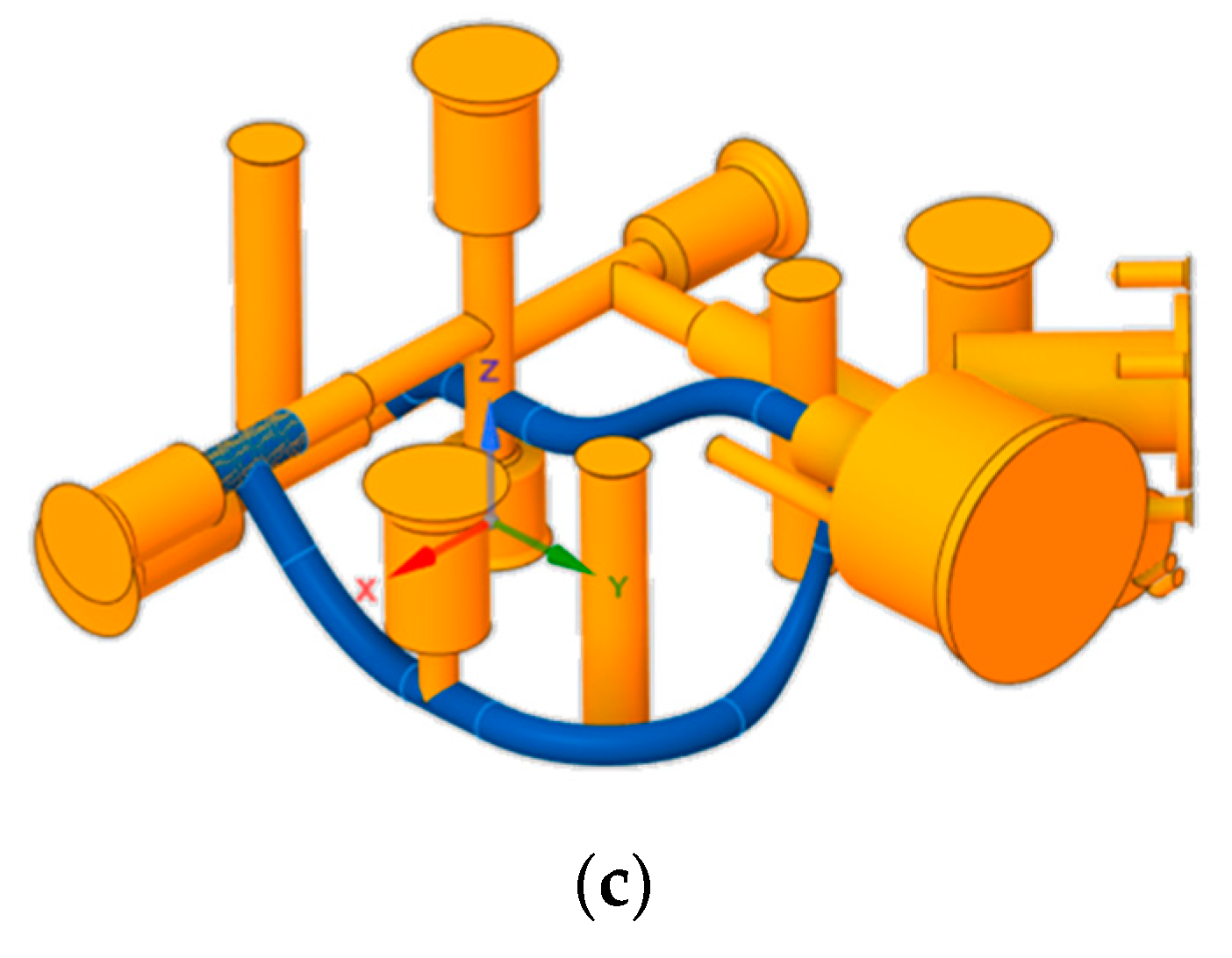
2.1. Design Optimization Process

Starting from an existing manifold for military applications (MA confidential data) in a 2024 aluminium alloy, a redesign for AM was made using CAD, with the aim of removing unnecessary mass and improving the fluid dynamic performance of the channels with pressurized oil. The starting constraints were represented by the positioning and size of cavities, ports and fixing points (Figure 1). dfAM allows for the removal of the auxiliary portions, such as connection channels, holes and plugs. Smooth channels allow for improved fluid dynamic performance, as the 90° angles typical of Computer Numerical Control (CNC) machining are no longer needed, as well as straight channels at a constant diameter. The design process started from the design of the fluidic part, always taking into account the future printability of the piece. Then, the metallic skin was drawn around the fluidic channel. Its typical initial thickness was 5 mm, suitable for pressures at stake. Through iterations with verification of the static resistance of the designed solution, the thickness of the metal skin of the canal was increased (typically up to max 40%), or ribs were introduced to the structures to allow adequate stiffening. The channels must by definition be self-supporting, because it would not be an additional value having to mechanically remove supports inside the channel by means of time-consuming post-processing. With circular sections up to 10 mm in diameter, this was generally verified. In this specific case, the maximum internal diameter of the channel was 7 mm. The external supports were then limited to the surfaces where these are strictly necessary, or where the geometry cannot be optimized for 3D printing due to the need to install the component or due to the interface. The surface that covered the various channels thus designed was joined to better distribute the tensions. Note that metal 3D printing offers opportunities not available for traditional CNC technologies: if stress concentrations or deformations occur during the modelling phase, it is always possible to change the section of the channel, increasing its size in some points, or smoothly passing from a circular section to elliptical and then return to circular. Once the geometry has been defined and validated, the raw model for 3D printing was defined with the addition of special allowances and, if needed, areas for anchoring to the base plate. The supports and the arrangement of the piece on the printing plate were defined with a 3D printing software (Materialise® Magics 3D [51]); with the proprietary software of the printer (EOS M290, 52), the process parameters of the building chamber were defined, (e.g., base plate temperature, argon flow speed, recoater speed, etc.), as well as the laser exposure set for parts and supports, including the metal powder layer thickness. The design of internal channels was based on minimizing the tensile stress due to the cyclic pressure loads; impulse testing is very essential in order to demonstrate the reliability of hydraulic systems especially in AM aerospace components. The objective was to reach a particular max principal stress within the fatigue limit, in this case of the alloy AlSi10Mg already characterized. A FE-based analysis might accurately detect where the highest stress concentration will be, but with more difficulty will accurately forecast the lifespan of the component since it cannot account for all of the production tolerances or other effects of the manufacturing process which can affect fatigue life. The more robust method of assessing failure modes and effects is to conduct an accelerated test which most closely replicates the operative conditions experienced during the service. One of the limitations of the AM technology as indicated in Table 1 is, in fact, the still narrow availability of experimental data representative of the metal alloys for layer-by-layer printing. Furthermore, the cyclic integrity at hydraulic impulse loads is an open topic worthy of being investigated to ensure an actual applicability in the aeronautical field. The workflow sees an iterative analysis process aimed at identifying the structural criticalities and smoothing them out with geometric adjustments (Figure 2). The most discharged areas identified were lightened by respecting the functional or assembly constraints. Once a threshold of structural safety margins was established, the design was “frozen” and examined for the layer-by-layer manufacturing process. All the drilling and turning operations for the threads were carried out on the final raw material. The test article was finally subjected to the main qualification tests listed in Table 2.
These groups of tests were carried out just in the certification stage. Subsequently, in the case of a qualified component an acceptance test procedure (ATP) was adequate to demonstrate serially the right operation of sub-systems before the in-service commissioning. It generally covered a performance and leakage test. The outcome of the current design activity was a manifold 40% lighter than the initial solution made by conventional CNC machining. A CFD analysis was not conducted in this redesign phase for AM, but it has been based on the empirical assumption that the fluid dynamic performance of the redesigned manifold in AM is equal to or better than that of a block produced by CNC with straight channels. Although the roughness inside the channels in the as-printed condition is higher, and therefore could induce a greater pressure drop, this would be amply compensated by the lower pressure drop deriving from the smooth connected channels.

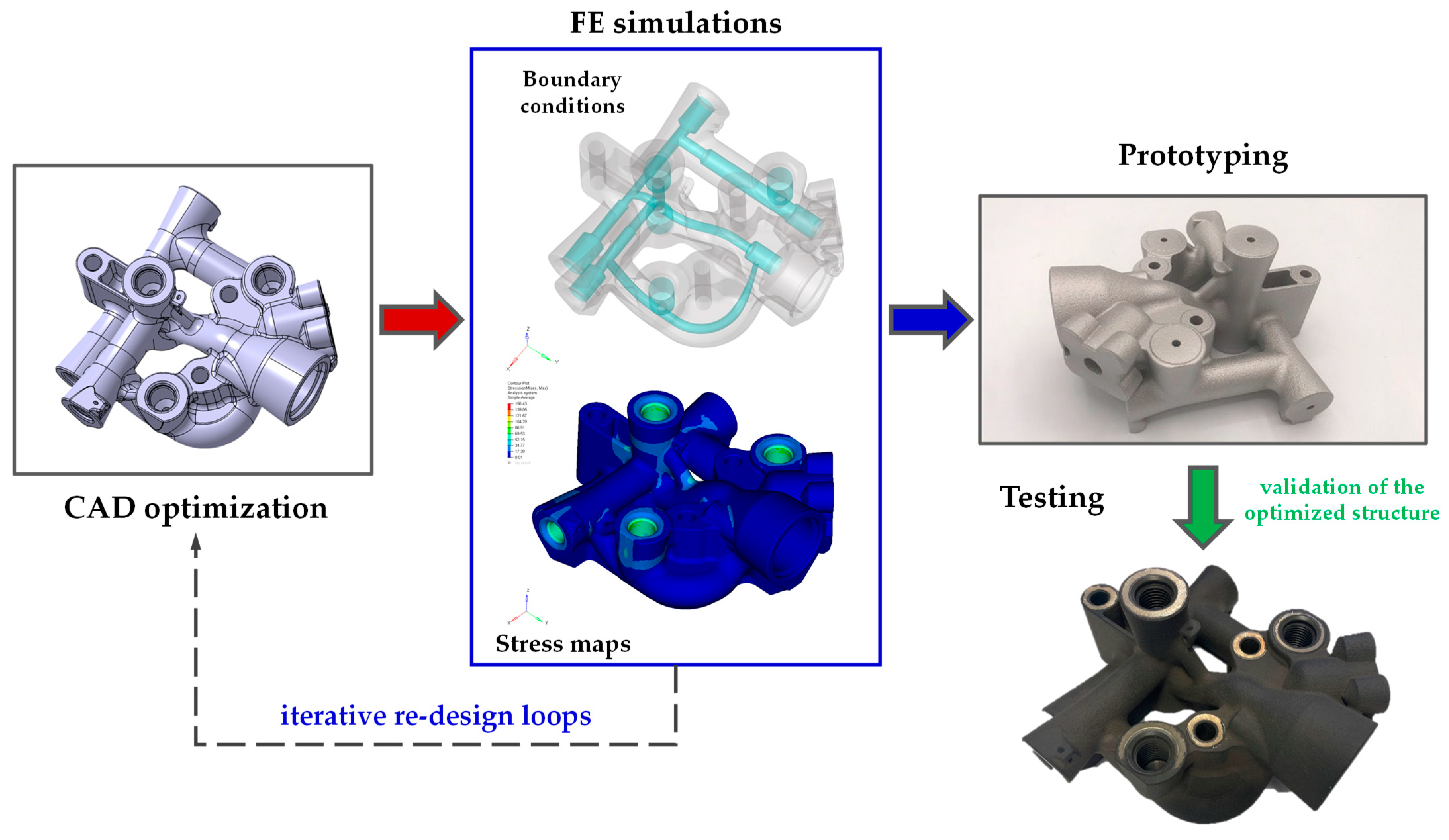
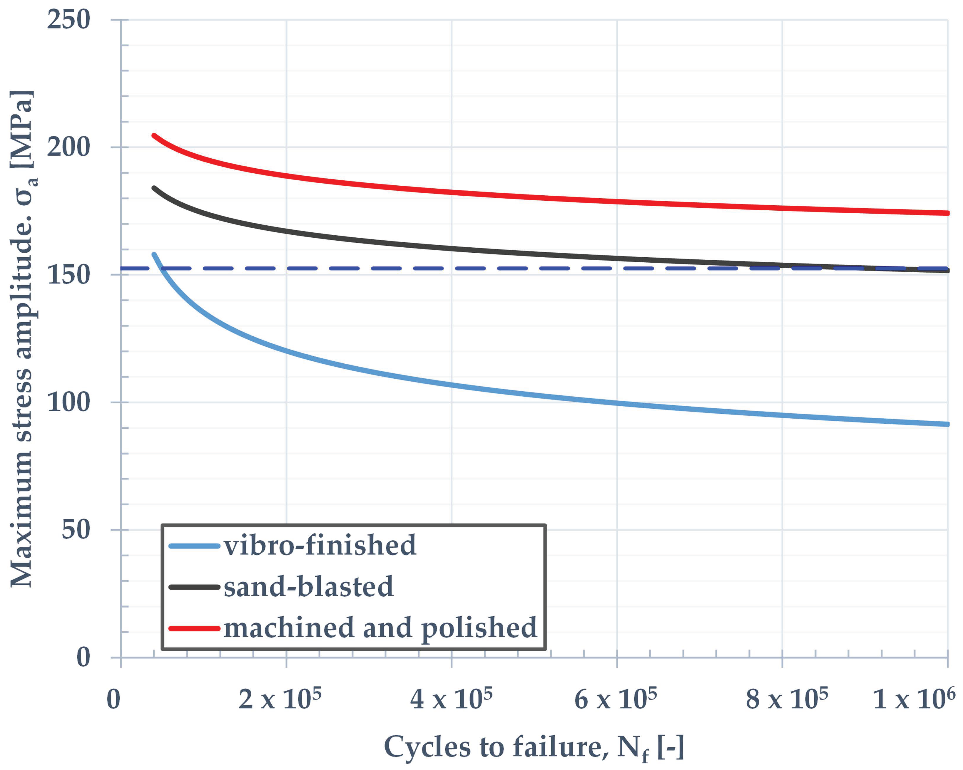
2.2. Material Properties Description

The material for the current application refers to an AlSi10Mg alloy already analysed by the Aidro company at sample level in previous projects; the 3D tester for this investigation was manufactured by an EOS M290 LPBF system (Krailling, Germany [52]) using a 400 W continuous Yb-fiber laser in Argon atmosphere. Strength properties depicted in Figure 3 were obtained according to EN ISO 6892-1:2016 standard [53] at room temperature by means of an MTS Alliance RT/100 universal testing frame (Minneapolis, MN, USA). The samples featured a gauge diameter of d = 8 mm and a gauge length of Lp = 40 mm, as recommended by standard [54] for fatigue testing. Uniaxial fatigue tests as per EN ISO 1099:2017 standard [54] were carried out with a fatigue stress ratio R = 0.1 at room temperature conditions for three different surface treatments (Figure 4). The static and fatigue data herein presented were extensively studied and discussed in the paper [55], from a cooperation of Aidro with Politecnico di Milano and Rosler Italiana Srl company.
Fatigue data regression was performed assuming a best-fit Basquin rule in log-log scale [55,56]. The stress amplitude (σa) as function of number of cycles to failure (Nf) can be expressed as Equation (1):
σ a = A ( N f ) B
The fatigue limit (FL) was statistically estimated on the basis of a minimum of 12 specimens per batch.
Vibro-finished, VF:Log(A) = 2.68 ± 0.07; B = −0.17 ± 0.01
Sand-blasted, SB:Log(A) = 2.24 ± 0.03; B = −0.06 ± 0.006
Machined and polished, MP:Log(A) = 2.24 ± 0.04; B = −0.05 ± 0.006
The vibro-finishing (VF) treatment was reached in a vibratory bowl filled with plastic abrasive cones media. Sand-blasting (SB) indicated a hand operation in a controlled-pressure closed environment using corundum spheres. It reflects the condition used for the herein presented hydraulic manifold. The third, more expensive case (MP, machining and polishing) allowed for the minimizing of surface and sub-surface flaws during the LPBF process. The relevant static and cyclic properties are listed in Table 3.

3. Structural Simulations

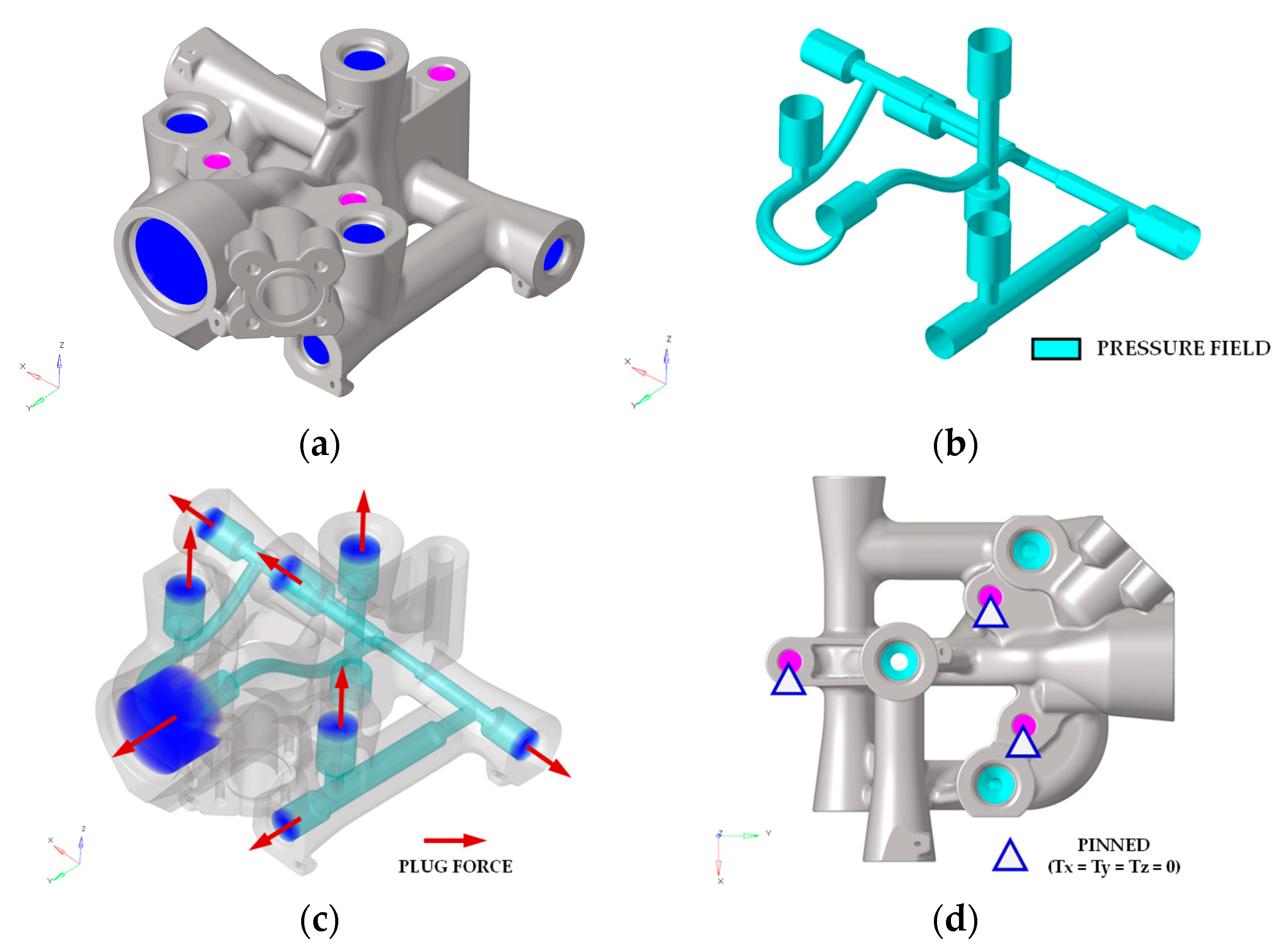
3.1. Load Conditions

The scope of this section is to provide the structural analysis of the hydraulic manifold with respect to the following loading cases detailed in Table 4.

3.2. Finite Element Model Description

Structural FE analysis was carried out using a 3D FEM modelling (in Altair Hypermesh environment); the 3D FE model is represented in Figure 5. A high density of nodes and elements (solid mesh ctet10 [62]) allowed for the easy identification of the stress distributions close to critical design details (hydraulic pipes, high curvature sections), generally the source of crack initiation. The main FE entities are listed in Table 5. The stress analysis was performed considering a uniform pressure field (pload4, [62]) acting on the internal wall surface (shell elements ctri3 [62]) (Figure 5b). Rigid elements rbe3 were used to schematize the plug reaction on the housing (Figure 5c) while rbe2 were used for positioning the external constraints (Figure 5d). The FE analyses were actually carried out considering the hydraulic manifold pinned (tx = ty = tz = 0) at the three interface holes.

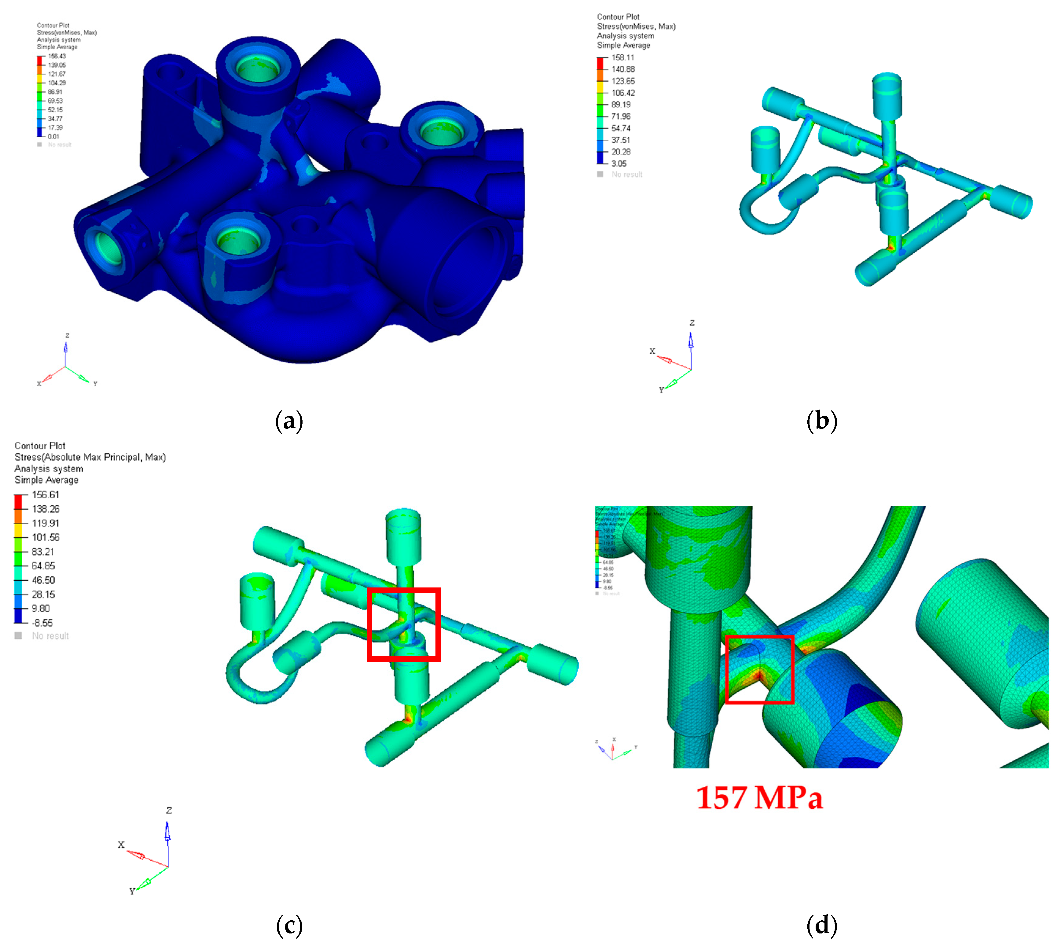
3.3. Finite Element Analysis Results

The structural FE analyses were performed with respect to the design hydraulic loads of Table 4. The final stress maps are represented in Figure 6. The Von Mises stress peak (158 MPa) occurred at the internal ducts, typically representing the critical areas of this kind of component (Figure 6b). The Max Principal stress field used for impulse fatigue analysis is given in Figure 6c; the relevant peak (157 MPa) is highlighted in Figure 6d. The design of the flow channels was iteratively updated in order to optimize the stress concentration factors, maintaining a maximum stress level contained within the fatigue limit estimated with the SN curves (Figure 4). Convergence studies were conducted in the critical areas to check the mesh size order assuming an error of about 1.0% acceptable. Safety margins at static and cyclic load are indicated in Table 6.

4. Qualification of Additively Manufactured Component for Use in Aircraft

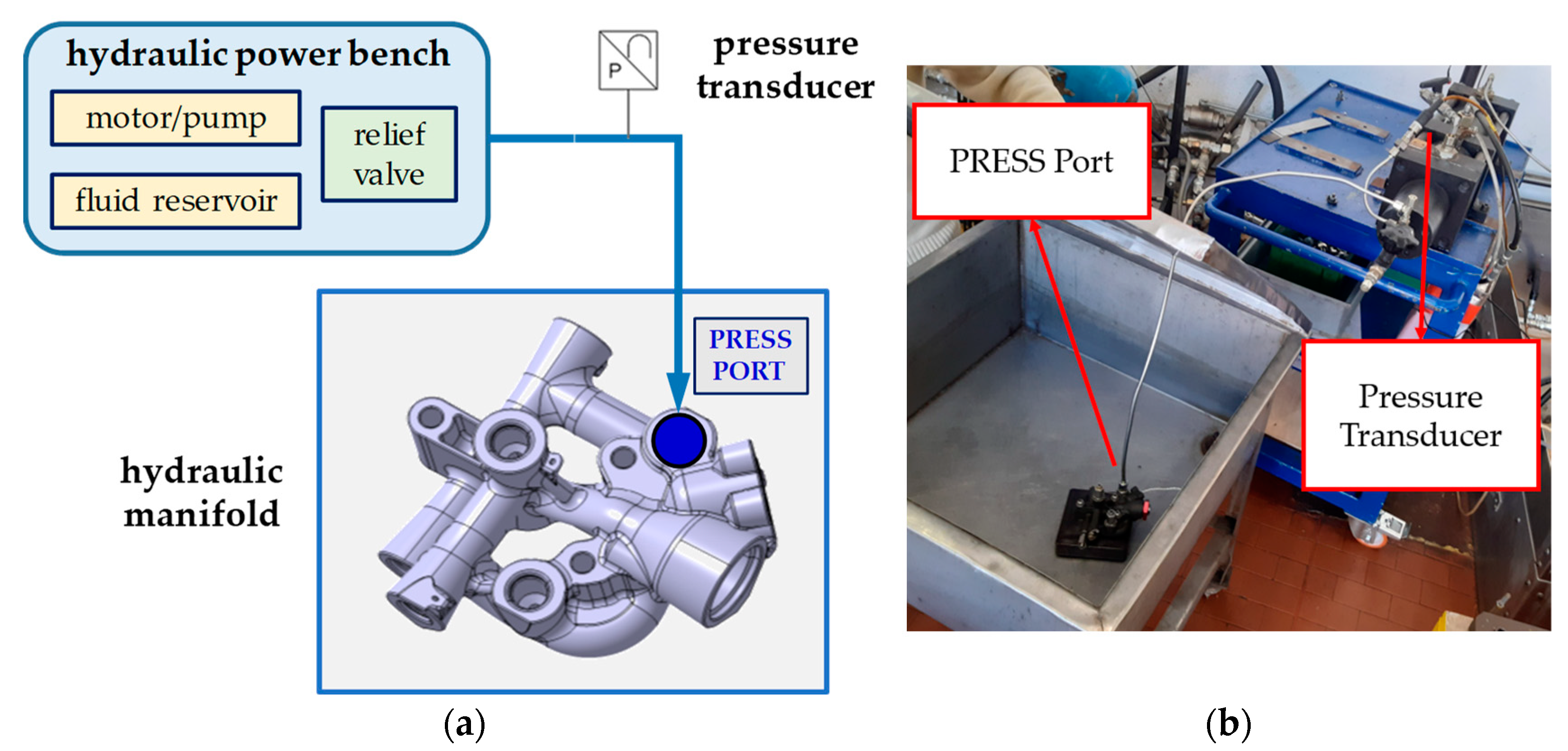
4.1. Qualification Hydraulic Tests Outline

In order to validate the compliance of the device with the airworthiness certification requirements, several structural tests have been performed on the AM hydraulic manifold. The following Table 7 summarizes the strength and endurance tests carried out. The burst pressure test was lastly performed because of its destructive nature. The qualification test campaign of the dfAM hydraulic manifold has been carried out at Magnaghi Aeronautica Laboratory, Naples, Italy.
A hydraulic fluid conforming to MIL-PRF-5606J type II was used for supply pressure [63]. The temperature was set at about (+30 ± 15 °C). The contamination level of the hydraulic fluid was class 7 or better as per NAS 1638.

4.2. Test Set-Up Description

The hydraulic fluid was supplied to the PRESS Port, while the pressure value was recorded by means of a pressure transducer (Figure 7). All the other ports were closed with actual plugs and hydraulic fittings.

4.3. Proof Pressure (Limit Load)

The proof pressure (PP) test demonstrates that the equipment is able to withstand a load of:
PP = 1.5 × DOP = 1.5 × 207 = 310.5 bar
without permanent deformation, pressure drop and external leakage. The hydraulic fluid was supplied at the PRESS port, increasing the pressure up to 310.5 bar and holding for 2 min (Figure 8), according to aeronautical standard SAE AS8775 [60].

4.4. Endurance Test

The main objective of this test is to determine the capability of the equipment of functioning without leakage or evidence of excessive wear or malfunctioning. The hydraulic manifold was tested for 5000 cycles as per the following sequence:
5 bar–(DOP = 207 bar)–185 bar–195 bar–(DOP = 207 bar)–5 bar
The hydraulic fluid was supplied at the PRESS port, increasing the pressure up to the desired values (Figure 9), according to the legacy qualification spectrum.

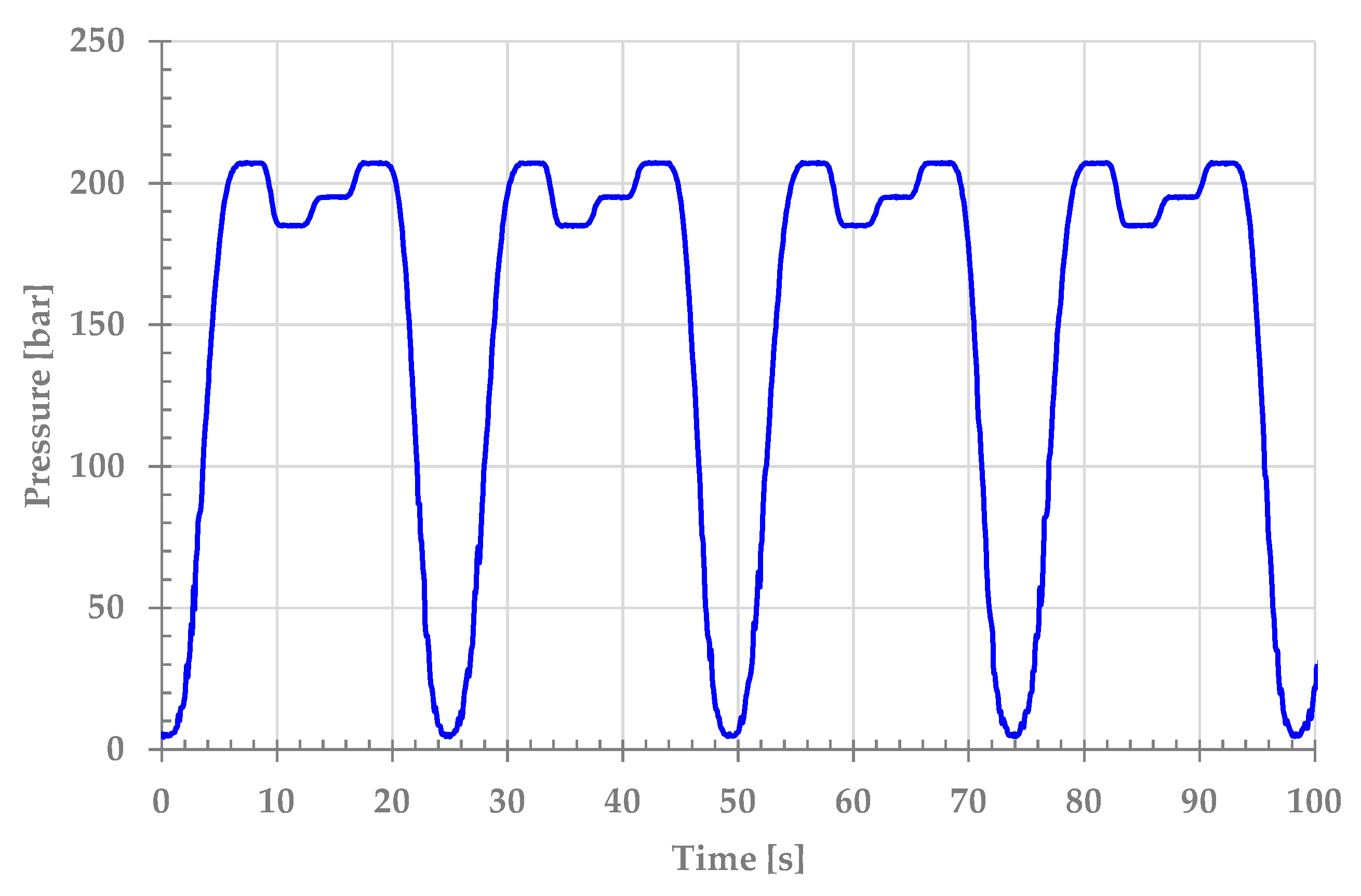
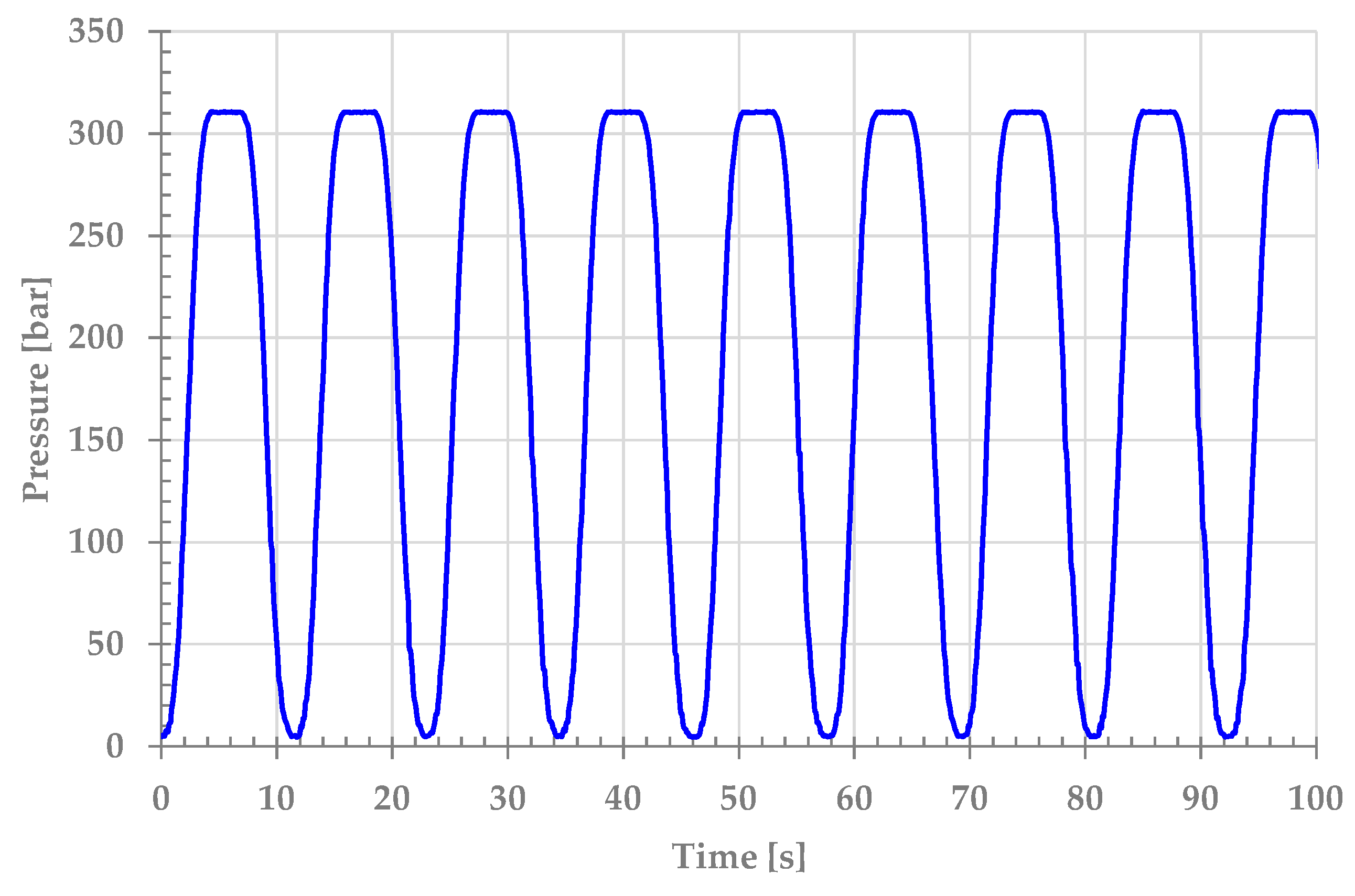
4.5. Impulse Fatigue Test

The main objective of this test is to demonstrate that the equipment is able to pass without failure or permanent deformation of any part of it when subjected to pressure impulse cycles. The hydraulic manifold was tested for 100,000 fatigue cycles supplying hydraulic fluid to the PRESS port according to the following pulse spectrum:
5 bar − (PP = 310.5 bar) − 5 bar
The spectrum is defined by aeronautical standard SAE ARP183 Rev. C [61]. The applicable alternate impulse trace for supply cavities is a square wave (Figure 10).

4.6. Burst Pressure (Ultimate Load)

The main objective of this test is to demonstrate that the equipment is able to withstand a load of:
BP = 2.5 × DOP = 2.5 × 207 = 517.5 bar
without rupture, pressure drop or external leakage.
The hydraulic fluid was supplied at the PRESS port, increasing the pressure up to 517.5 bar and holding for 3 s, according to aeronautical standard SAE AS8775 [60]. The pressure load profile is represented in Figure 11.

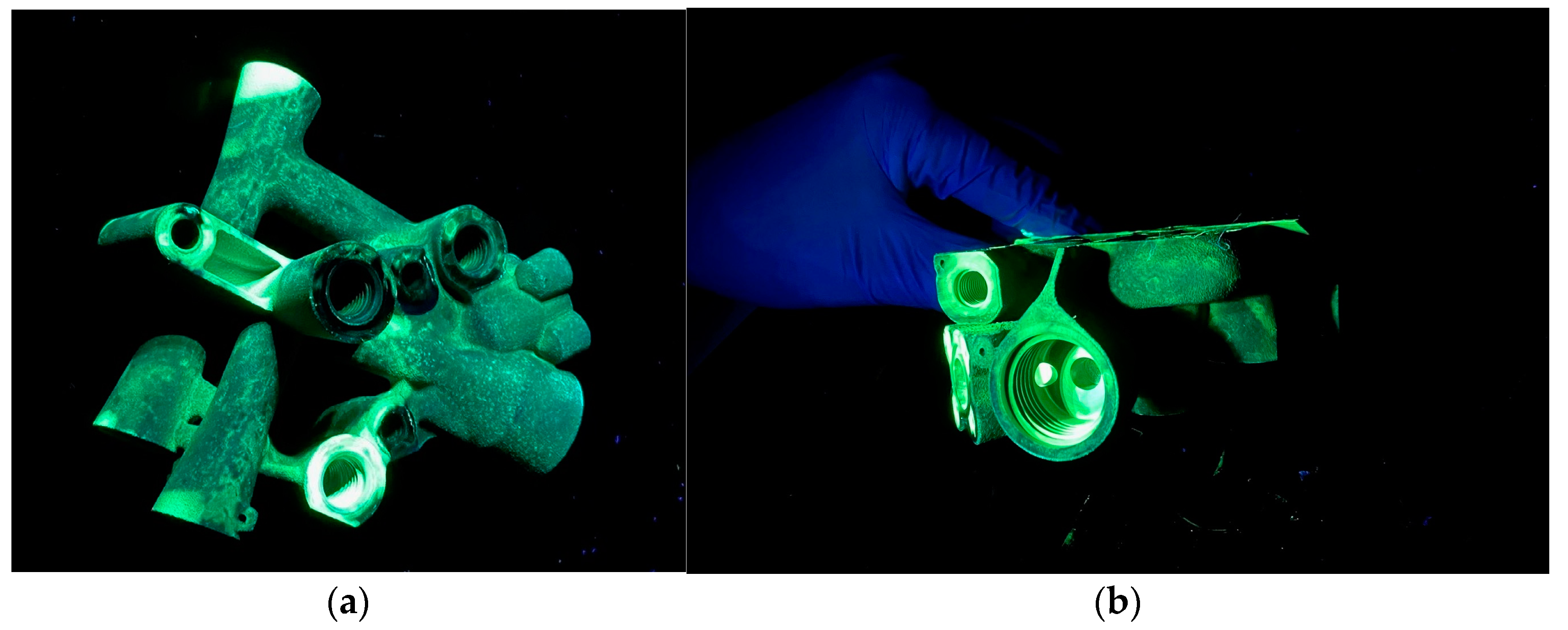
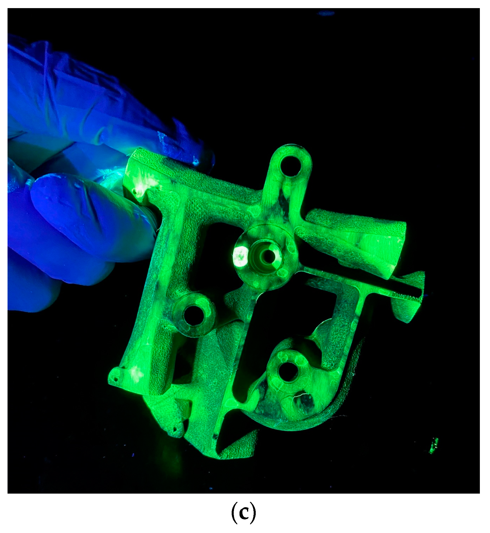
4.7. Experimental Results

A visual inspection was performed on the test article at the end of each test in order to verify the compliance with the requirements. After the completion of the test campaign, the AM hydraulic manifold was subjected to NDT checks, by means of Dye Penetrant Inspection (DPI) in order to detect cracks, in particular on the surface and threads, according to standards ASTM E 1417 [64] and EN ISO 3452 [65]. The AM hydraulic manifold was preliminarily pre-cleaned to remove any dirt, oil, grease or any loose scale that could either keep penetrant out of a defect or cause false indication. Then, the penetrant was applied to the test component by dipping. After a dwell time of 30 min to soak the penetrant into any flaws, the excess penetrant was removed from the surface, then a contrasting developer was applied on the surface. The item was inspected under an ultraviolet light in a dark room to look for indications that there may be cracks or other surface discontinuities. No anomalies on the AM hydraulic manifold were detected during the inspection. The photos taken during the DPI are shown in Figure 12.
The compliance to the following airworthiness certification requirements has been verified:
-
No permanent deformation and evidence of external leakage or pressure drops have been detected following the limit load (PP pressure);
-
No external leakage, excessive wear, malfunctioning, excessive abrasion, damage or excessive backlash was detected after the endurance test;
-
No cracks of any part of the item or external leakage occurred during the pulse fatigue test;
-
No fracture occurred at ultimate load (BP pressure).

5. Conclusions

The current paper demonstrates the standard AM-based process that could be followed for optimizing conventionally manufactured components. Starting from a highly mature technological solution of a hydraulic manifold already certified, the case study explained in this paper walks through the iterative AM steps in the re-engineering of a lightweight version with over 40% weight savings. The valve is part of a module for controlling the extension and retraction of a landing gear system in an emergency case. Hydraulic components for aeronautical applications need to satisfy tight strength requirements (i.e., proof, burst, endurance and impulse pressure are generally the most critical load conditions). In view of these issues—decisive for full release into service—the optimization was rationally driven by the structural integrity aspects. The characterization of AM-based components at impulse loads still represents a crucial topic to be well investigated in order to validate the technology maturity and its readiness for certification, due to the lack of industrial production standards and consequent uncertainties on allowable designs. The FE simulations predictively supported the shape modifications in order to minimize the stress concentrations by improving the fatigue behaviour. Experimental demonstrations according to aeronautical equipment qualification standards successfully validated the design process. In this way, the hydraulic manifold technology experienced a well-sustained maturation process up to the consolidation of a full-scale prototype for final functionality tests in real operative conditions. Along this direction, research lines will be encouraged and oriented to the following key-points:
  • Defining solid certification specifications and processes;
  • Reducing the mechanical complexity by decreasing the number of constitutive parts and replacing entire sub-assemblies with integral components;
  • Streamlining the manufacturing and assembly steps through the adoption of rational design solutions for fast series production.
The next activities will concern the development of a fully automatic procedure to improve the flow channels, also with respect to the thermo-hydraulic performances and environmental compatibility not explicitly addressed here.

Author Contributions

All the authors (M.A., P.A., V.R., F.B., T.T. and M.C.) have equally contributed to this research paper. All authors have read and agreed to the published version of the manuscript.

Funding

This research received no external funding.

Data Availability Statement

Data sharing not applicable.

Acknowledgments

The authors are grateful to all four reviewers for their critical and constructive comments on this paper.

Conflicts of Interest

The authors declare no conflict of interest.

References

  1. Yadroitsev, I.; Yadroitsava, I.; du Plessis, A.; MacDonald, E. Fundamentals of Laser Powder Bed Fusion of Metals, 1st ed.; Elsevier Inc.: Amsterdam, The Netherlands, 2021. [Google Scholar]
  2. Gibson, I.; Rosen, D.; Stucker, B. Additive Manufacturing Technologies: 3D Printing, Rapid Prototyping, and Direct Digital Manufacturing, 2nd ed.; Springer: New York, NY, USA, 2015. [Google Scholar]
  3. Minet, K.; Saharan, A.; Loesser, A.; Raitanen, N. Superalloys, powders, process monitoring in additive manufacturing. In Additive Manufacturing for the Aerospace Industry; Elsevier Inc.: Amsterdam, The Netherlands, 2019; pp. 163–185. [Google Scholar] [CrossRef]
  4. Gradl, P.R.; Greene, S.E.; Protz, C.; Bullard, B.; Buzzell, J.; Garcia, C.; Wood, J.; Osborne, R.; Hulka, J.; Cooper, K.G. Additive Manufacturing of Liquid Rocket Engine Combustion Devices: A Summary of Process Developments and Hot-Fire Testing Results. In Proceedings of the 2018 Joint Propulsion Conference, Cincinnati, OH, USA, 9–11 July 2018. [Google Scholar] [CrossRef] [Green Version]
  5. Blakey-Milner, B.; Gradl, P.; Snedden, G.; Brooks, M.; Pitot, J.; Lopez, E.; Leary, M.; Berto, F.; du Plessis, A. Metal additive manufacturing in aerospace: A review. Mater. Des. 2021, 209, 110008. [Google Scholar] [CrossRef]
  6. Najmon, J.C.; Raeisi, S.; Tovar, A. Review of additive manufacturing technologies and applications in the aerospace industry. In Additive Manufacturing for the Aerospace Industry; Elsevier: Amsterdam, The Netherlands, 2019; pp. 7–31. [Google Scholar]
  7. Allen, J. An Investigation into the Comparative Costs of Additive Manufacture vs. Machine from Solid for Aero Engine Parts, Cost Effective Manufacture via Net-Shape Processing; Proc. Meet. RTO-MP-AVT-139, Neuilly-sur-Seine, France, May 2006, NATO; ROLLS-ROYCE PLC: Derby, UK, 2006; pp. 17-1–17-10. [Google Scholar]
  8. Joshi, S.C.; Sheikh, A.A. 3D printing in aerospace and its long-term sustainability. Virtual Phys. Prototyp. 2015, 10, 175–185. [Google Scholar] [CrossRef]
  9. Gebler, M.; Schoot Uiterkamp, A.J.M.; Visser, C. A global sustainability perspective on 3D printing technologies. Energy Policy 2014, 74, 158–167. [Google Scholar] [CrossRef]
  10. Uriondo, A.; Esperon-Miguez, M.; Perinpanayagam, S. The present and future of additive manufacturing in the aerospace sector: A review of important aspects. Proc. Inst. Mech. Eng. Part G J. Aerosp. Eng. 2015, 229, 2132–2147. [Google Scholar] [CrossRef]
  11. Pereira, J.; Borovkov, H.; Zubiri, F.; Guerra, M.; Caminos, J. Optimization of Thin Walls with Sharp Corners in SS316L and IN718 Alloys Manufactured with Laser Metal Deposition. J. Manuf. Mater. Process. 2021, 5, 5. [Google Scholar] [CrossRef]
  12. Gradl, P.R.; Protz, C.S.; Wammen, T. Additive Manufacturing and Hot-fire Testing of Liquid Rocket Channel Wall Nozzles Using Blown Powder Directed Energy Deposition Inconel 625 and JBK-75 Alloys. In Proceedings of the AIAA Propulsion and Energy 2019 Forum, Indianapolis, IN, USA, 19–22 August 2019. [Google Scholar] [CrossRef]
  13. Yu, J.; Rombouts, M.; Maes, G.; Motmans, F. Material Properties of Ti6Al4V Parts Produced by Laser Metal Deposition. Phys. Procedia 2012, 39, 416–424. [Google Scholar] [CrossRef] [Green Version]
  14. Kelly, S.M.; Kampe, S.L. Microstructural evolution in laser-deposited multilayer Ti-6Al-4V builds: Part II. Thermal modeling. Met. Mater. Trans. A 2004, 35, 1869–1879. [Google Scholar] [CrossRef]
  15. Kelly, S.M.; Kampe, S.L. Microstructural evolution in laser-deposited multilayer Ti-6Al-4V builds: Part I. Microstructural characterization. Met. Mater. Trans. A 2004, 35, 1861–1867. [Google Scholar] [CrossRef]
  16. Antonysamy, A. Microstructure, Texture and Mechanical Property Evolution during Additive Manufacturing of Ti6Al4V Alloy for Aerospace Applications. Ph.D. Dissertation, University of Manchester, Manchester, UK, 2012. [Google Scholar]
  17. Wang, F.; Williams, S.; Colegrove, P.; Antonysamy, A.A. Microstructure and Mechanical Properties of Wire and Arc Additive Manufactured Ti-6Al-4V. Met. Mater. Trans. A 2012, 44, 968–977. [Google Scholar] [CrossRef]
  18. Ladani, L.; Sadeghilaridjani, M. Review of Powder Bed Fusion Additive Manufacturing for Metals. Metals 2021, 11, 1391. [Google Scholar] [CrossRef]
  19. Yap, C.Y.; Chua, C.K.; Dong, Z.L.; Liu, Z.H.; Zhang, D.Q.; Loh, L.E.; Sing, S.L. Review of selective laser melting: Materials and applications. Appl. Phys. Rev. 2015, 2, 041101. [Google Scholar] [CrossRef]
  20. Bhavar, V.; Kattire, P.; Patil, V.; Khot, S.; Gujar, K.; Singh, R. A review on powder bed fusion technology of metal additive manufacturing. In Proceedings of the 4th International conference and exhibition on Additive Manufacturing Technologies-AM-2014, Bangalore, India, 1–2 September 2014; pp. 1–2. [Google Scholar]
  21. Emmelmann, C.; Herzog, D.; Kranz, J. Design for Laser Additive Manufacturing; Elsevier BV: Amsterdam, The Netherlands, 2017; pp. 259–279. [Google Scholar]
  22. Singamneni, S.; Lv, Y.; Hewitt, A.; Chalk, R.; Thomas, W.; Jordison, D. Additive Manufacturing for the Aircraft Industry: A Review. J. Aeronaut. Aerosp. Eng. 2019, 8, 214. [Google Scholar] [CrossRef] [Green Version]
  23. Ford, S.; Despeisse, M. Additive manufacturing and sustainability: An exploratory study of the advantages and challenges. J. Clean. Prod. 2016, 137, 1573–1587. [Google Scholar] [CrossRef]
  24. Altıparmak, S.C.; Xiao, B. A market assessment of additive manufacturing potential for the aerospace industry. J. Manuf. Process. 2021, 68, 728–738. [Google Scholar] [CrossRef]
  25. Zitelli, C.; Folgarait, P.; Di Schino, A. Laser Powder Bed Fusion of Stainless Steel Grades: A Review. Metals 2019, 9, 731. [Google Scholar] [CrossRef] [Green Version]
  26. Manfredi, D.; Bidulský, R. Laser Powder Bed Fusion of Aluminum Alloys. Acta Met. Slovaca 2017, 23, 276–282. [Google Scholar] [CrossRef] [Green Version]
  27. Sabzi, H.E. Powder bed fusion additive layer manufacturing of titanium alloys. Mater. Sci. Technol. 2019, 35, 875–890. [Google Scholar] [CrossRef]
  28. Tian, Z.; Zhang, C.; Wang, D.; Liu, W.; Fang, X.; Wellmann, D.; Zhao, Y.; Tian, Y. A Review on Laser Powder Bed Fusion of Inconel 625 Nickel-Based Alloy. Appl. Sci. 2019, 10, 81. [Google Scholar] [CrossRef] [Green Version]
  29. DebRoy, T.; Wei, H.L.; Zuback, J.S.; Mukherjee, T.; Elmer, J.W.; Milewski, J.O.; Beese, A.M.; Wilson-Heid, A.; De, A.; Zhang, W. Additive manufacturing of metallic components–Process, structure and properties. Prog. Mater. Sci. 2018, 92, 112–224. [Google Scholar] [CrossRef]
  30. Seifi, M.; Gorelik, M.; Waller, J.; Hrabe, N.; Shamsaei, N.; Daniewicz, S.; Lewandowski, J.J. Progress Towards Metal Additive Manufacturing Standardization to Support Qualification and Certification. Jom 2017, 69, 439–455. [Google Scholar] [CrossRef]
  31. Sun, Y.Y.; Lu, S.L.; Gulizia, S.; Oh, C.H.; Fraser, D.; Leary, M.; Qian, M. Fatigue Performance of Additively Manufactured Ti-6Al-4V: Surface Condition vs. Internal Defects. Jom 2020, 72, 1022–1030. [Google Scholar] [CrossRef]
  32. Sanaei, N.; Fatemi, A. Defects in additive manufactured metals and their effect on fatigue performance: A state-of-the-art review. Prog. Mater Sci. 2021, 117, 100724. [Google Scholar] [CrossRef]
  33. du Plessis, A.; Yadroitsava, I.; Yadroitsev, I. Effects of defects on mechanical properties in metal additive manufacturing: A review focusing on X-ray tomography insights. Mater. Des. 2019, 187, 108385. [Google Scholar] [CrossRef]
  34. du Plessis, A.; Beretta, S. Killer notches: The effect of as-built surface roughness on fatigue failure in AlSi10Mg produced by laser powder bed fusion. Addit. Manuf. 2020, 35, 101424. [Google Scholar] [CrossRef]
  35. Uzan, N.E.; Ramati, S.; Shneck, R.; Frage, N.; Yeheskel, O. On the effect of shot-peening on fatigue resistance AlSi10Mg specimens fabricated by additive manufacturing using selective laser melting (AM-SLM). Addit. Manuf. 2018, 21, 458–464. [Google Scholar] [CrossRef]
  36. Masuo, H.; Tanaka, Y.; Morokoshi, S.; Yagura, H.; Uchida, T.; Yamamoto, Y.; Murakami, Y. Influence of defects, surface roughness and HIP on the fatigue strength of Ti-6Al-4V manufactured by additive manufacturing. Int. J. Fatigue 2018, 117, 163–179. [Google Scholar] [CrossRef]
  37. Renishaw. Hydraulic Block Manifold Redesign for Additive Manufacturing. 2016. Available online: www.renishaw.com (accessed on 30 October 2022).
  38. Biedermann, M.; Beutler, P.; Meboldt, M. Automated design of additive manufactured flow components with consideration of overhang constraint. Addit. Manuf. 2021, 46, 102119. [Google Scholar] [CrossRef]
  39. Diegel, O.; Schutte, J.; Ferreira, A.; Chan, Y.L. Design for additive manufacturing process for a lightweight hydraulic manifold. Addit. Manuf. 2020, 36, 101446. [Google Scholar] [CrossRef]
  40. Alshare, A.A.; Calzone, F.; Muzzupappa, M. Hydraulic manifold design via additive manufacturing optimized with CFD and fluid-structure interaction simulations. Rapid Prototyp. J. 2019, 25, 1516–1524. [Google Scholar] [CrossRef]
  41. Schmelzle, J.; Kline, E.V.; Dickman, C.J.; Reutzel, E.W.; Jones, G.; Simpson, T.W. (Re)Designing for Part Consolidation: Understanding the Challenges of Metal Additive Manufacturing. J. Mech. Des. 2015, 137, 111404. [Google Scholar] [CrossRef]
  42. Zhu, Y.; Wang, S.; Zhang, C.; Yang, H. Am-Driven Design of Hydraulic Manifolds: Enhancing Fluid Flow and Reducing Weight; Technische Universität Dresden: Dresden, Germany, 2020. [Google Scholar] [CrossRef]
  43. Engineering, S.A. Aero-Engine. Available online: https://sief.org.au/wp-content/uploads/2019/02/RP04-153AeroFinalReportSummary.pdf (accessed on 16 December 2022).
  44. Airbus, E. Hydraulic Spoiler Manifold. Available online: https://www.eos.info/01_parts-andapplications/case_studies_applications_parts/_case_studies_pdf/en_cases/cs_m_aerospace_liebherr_en.pdf (accessed on 16 December 2022).
  45. Airbus, L.-A. Landing Gear Sensor Bracket. Available online: https://amfg.ai/2020/01/23/applications-spotlight-3d-printed-brackets/ (accessed on 16 December 2022).
  46. Zhan, Z.; Li, H.; Lam, K. Development of a novel fatigue damage model with AM effects for life prediction of com-monly-used alloys in aerospace. Int. J. Mech. Sci. 2019, 155, 110–124. [Google Scholar] [CrossRef]
  47. Dagkolu, A.; Gokdag, I.; Yilmaz, O. Design and additive manufacturing of a fatigue-critical aerospace part using topology optimization and L-PBF process. Procedia Manuf. 2021, 54, 238–243. [Google Scholar] [CrossRef]
  48. Kahlin, M. 3D-printing for Aerospace: Fatigue Behaviour of Additively Manufactured Titanium. Ph.D. Dissertation, Linköping University, Linköping, Sweden, 2021. [Google Scholar]
  49. Tomlin, M.; Meyer, J. Topology optimization of an additive layer manufactured (ALM) aerospace part. In Proceedings of the 7th Altair CAE Technology Conference 2011, Warwickshire, UK, 10 May 2011; pp. 1–9. [Google Scholar]
  50. Meng, L.; Zhang, W.; Quan, D.; Shi, G.; Tang, L.; Hou, Y.; Breitkopf, P.; Zhu, J.; Gao, T. From Topology Optimization Design to Additive Manufacturing: Today’s Success and Tomorrow’s Roadmap. Arch. Comput. Methods Eng. 2019, 27, 805–830. [Google Scholar] [CrossRef]
  51. Materialise® Magics 3D Print Suite: Leuven, Belgium. Available online: https://www.materialise.com/ (accessed on 30 October 2022).
  52. Krailling/Munich, Germany. Available online: https://www.eos.info (accessed on 30 October 2022).
  53. EN ISO 6892-1:2016; Metallic Materials, Tensile Testing, Part 1: Method of Test at Room Temperature. International Organization for Standardization: Geneva, Switzerland, 2016.
  54. EN ISO 1099:2017; Metallic Materials, Fatigue Testing, Axial Force-Controlled Method. International Organization for Standardization: Geneva, Switzerland, 2017.
  55. Nasab, M.H.; Giussani, A.; Gastaldi, D.; Tirelli, V.; Vedani, M. Effect of Surface and Subsurface Defects on Fatigue Behavior of AlSi10Mg Alloy Processed by Laser Powder Bed Fusion (L-PBF). Metals 2019, 9, 1063. [Google Scholar] [CrossRef] [Green Version]
  56. Santecchia, E.; Hamouda, A.M.S.; Musharavati, F.; Zalnezhad, E.; Cabibbo, M.; El Mehtedi, M.; Spigarelli, S. A Review on Fatigue Life Prediction Methods for Metals. Adv. Mater. Sci. Eng. 2016, 2016, 9573524. [Google Scholar] [CrossRef] [Green Version]
  57. Aboulkhair, N.T.; Maskery, I.; Tuck, C.; Ashcroft, I.; Everitt, N.M. Improving the fatigue behaviour of a selectively laser melted aluminium alloy: Influence of heat treatment and surface quality. Mater. Des. 2016, 104, 174–182. [Google Scholar] [CrossRef]
  58. Uzan, N.E.; Shneck, R.; Yeheskel, O.; Frage, N. Fatigue of AlSi10Mg specimens fabricated by additive manufacturing selective laser melting (AM-SLM). Mater. Sci. Eng. A 2017, 704, 229–237. [Google Scholar] [CrossRef]
  59. Bagherifard, S.; Beretta, N.; Monti, S.; Riccio, M.; Bandini, M.; Guagliano, M. On the fatigue strength enhancement of additive manufactured AlSi10Mg parts by mechanical and thermal post-processing. Mater. Des. 2018, 145, 28–41. [Google Scholar] [CrossRef]
  60. SAE-AS8775; Military Specification: Hydraulic System Components, Aircraft and Missiles, General Specification for AS8775. SAE International: Warrendale, PA, USA, 28 September 1998.
  61. SAE ARP1383; Aerospace—Impulse Testing of Hydraulic Components, rev. C. SAE International: Warrendale, PA, USA, April 2013.
  62. MSC Nastran®. Quick Reference Guide 2021; MSC Software: Newport Beach, CA, USA, 2021. [Google Scholar]
  63. MIL-PRF-5606J; Performance Specification: Hydraulic Fluid, Petroleum Base; Aircraft, Missile, and Ordnance. U.S. Department of Defense Military Specifications and Standards: Arlington County, VA, USA, 5 March 2018.
  64. ASTM E1417/E1417M; Standard Practice for Liquid Penetrant Testing. ASTM International: West Conshohocken, PA, USA, 2021.
  65. EN ISO 3452-1:2021; Non-Destructive Testing—Liquid Penetrant Testing. International Organization for Standardization: Geneva, Switzerland, 2021.
Figure 1. Automated CAD steps used for redesign of AM hydraulic manifold. (a) initial ducts of the conventional manifold (user input); (b) design optimization for AM: channel to be redesigned (blue); plugs to be removed (red); (c) final ducts of the AM manifold (user output).
Aerospace 10 00069 g001aAerospace 10 00069 g001b
Figure 2. Design optimization flowchart.
Aerospace 10 00069 g002
Figure 3. Tensile test curves of LPBF processed AlSi10Mg alloy [54,55].
Aerospace 10 00069 g003
Figure 4. Fatigue curves based on Basquin fitting of the LPBF processed AlSi10Mg alloy [54,55].
Aerospace 10 00069 g004
Figure 5. Three-dimensional FE model details. (a) 3D model; (b) inner walls; (c) equivalent hydraulic loads on plugs; (d) constraints.
Aerospace 10 00069 g005
Figure 6. Stress maps (limit pressure load, PP = 31.05 MPa). (a) Von Mises stress (outer walls); (b) Von Mises stress (inner flow channels); (c) Max Principal stress (inner flow channels); (d) zoom on Max Principal peak.
Aerospace 10 00069 g006
Figure 7. Hydraulic manifold test stand. (a) hydraulic layout; (b) lab setup.
Aerospace 10 00069 g007
Figure 8. Proof pressure test: load profile.
Aerospace 10 00069 g008
Figure 9. Endurance test spectrum.
Aerospace 10 00069 g009
Figure 10. Test spectrum of impulse fatigue.
Aerospace 10 00069 g010
Figure 11. Burst pressure test: load profile.
Aerospace 10 00069 g011
Figure 12. Fluorescent Penetrant Inspection. (a) upper side view; (b) detail of threaded part; (c) bottom side.
Aerospace 10 00069 g012aAerospace 10 00069 g012b
Table 1. Main features of AM in the aerospace industry.
BenefitsLimitations
  • “design freedom”
  • lack of certifications and standardizations
  • parts number reduction
  • high material cost
  • material waste minimization
  • need of a mechanical properties database
  • reduced lead time to market
  • high-cost investment required for first time
  • corrosion mitigation
  • equipment and facility requirements
  • green manufacturing inspired
  • expertise profile required
Table 2. Qualification matrix.
Type of TestTest
Functionalperformance/function
leakage
Structuralproof pressure
endurance
fatigue,
burst pressure
Environmentaltemperature (high/low)
shock and vibrations
lightening
contamination
Table 3. Main structural properties of AlSi10Mg [55].
Elastic modulus, Exy plane: 70 ± 10[GPa]
z-dir: 60 ± 10
Yield strength, YS228 ± 4.1[MPa]
Tensile strength, UTS412 ± 5.5[MPa]
Fatigue limit, FLAs-Build: 50–62 [57,58,59][MPa]
VF: 95.0 ± 4.5
SB: 152.5 ± 3.5
MP: 194.0 ± 10.0
Table 4. Hydraulic load conditions applied [60,61].
Load ConditionPressure
Proof pressure310.5 bar
Burst pressure517.5 bar
Impulse pressure0.5–310.5–0.5 bar
(for 100,000 cycles)
Table 5. Three-dimensional FE model total number of nodes and elements.
FE EntityNumber
Nodes3,718,280
3D elements, ctet102,476,870
2D elements, ctri371,588
0D elements, rbe11
Table 6. Finite element analysis results.
Load CaseDescriptionSafety Margin/Damage
Proof pressureStaticMSlim = (228/158) − 1 = 0.44
Burst pressureStaticMSult = (412/263) − 1 = 0.57
Impulse pressureFatigueD = 1 × 10⁵/1 × 106 = 0.1 < 1.0
Table 7. Summary of qualification tests.
TestN. of CyclesReference
1. Proof Pressure-SAE AS8775 [60]
2. Endurance Cycles5000Legacy spectrum
3. Hydraulic Fatigue100,000SAE ARP183 Rev. C [61]
4. Burst Pressure-SAE AS8775 [60]
Disclaimer/Publisher’s Note: The statements, opinions and data contained in all publications are solely those of the individual author(s) and contributor(s) and not of MDPI and/or the editor(s). MDPI and/or the editor(s) disclaim responsibility for any injury to people or property resulting from any ideas, methods, instructions or products referred to in the content.

