Article

Computational Fluid Dynamics Analyses of a Wing with Distributed Electric Propulsion

1
Engineering Department, Università della Campania “L. Vanvitelli”, Via Roma 29, 81031 Aversa, CE, Italy
2
Italian Aerospace Research Center “CIRA”, Via Maiorise, 81043 Capua, CE, Italy
*
Author to whom correspondence should be addressed.
Aerospace 2023, 10(1), 64; https://doi.org/10.3390/aerospace10010064
Submission received: 26 November 2022 / Revised: 22 December 2022 / Accepted: 5 January 2023 / Published: 8 January 2023
(This article belongs to the Special Issue Fluid Flow Mechanics (2nd Edition))

Abstract

:
The efficiency increase that distributed propulsion could deliver for future hybrid-electric aircraft is in line with the urgent demand for higher aerodynamic performances and a lower environmental impact. Several consolidated proprietary tools (not always available) are developed worldwide for distributed propulsion simulation. Therefore, prediction and comparisons of propeller performances, with computational fluid dynamic codes featuring different implementation of solvers, numerical schemes, and turbulence models, is of interest to a wider audience of research end-users. In this framework, the paper presents a cross-comparison study among different CFD solvers, the SU2 Multiphysics Simulation and Design Software, the CIRA proprietary flow solver UZEN, and the commercial ANSYS-FLUENT code, for the simulation of a wing section with a tractor propeller at different flow attitudes. The propeller is modelled as an actuator disk according to the general momentum theory and is accounted for in the flow solvers as a boundary condition, for the momentum and energy equations. In this study, a propeller with a fixed advance ratio J = 0.63 is considered, while propeller performances are assumed variable along with the radius. To perform the comparisons among the solvers, an in-house procedure, which provides the input thrust and torque distributions in a unified format among the three solvers, is developed. Steady RANS simulations are performed at R e = 1.7 × 10 6 and M = 0.11 , for the flowfield of an isolated propeller. Successively, a wing section with a fixed forward-mounted propeller configuration with no nacelle, is studied at α = 0 , 4 , and 8 angles of attack. The comparisons in terms of the lift coefficient show a good agreement among the three flow solvers both in power-off and power-on conditions. Simulations also evidenced the strong stability preserving property of upwind schemes, applied to propeller simulation at low-Mach number. Some discrepancies in the drag coefficient are observed and related to different levels of numerical diffusion between the three codes, which affects the downstream wake. Differences in flow properties in near disk region are observed and explained considering the different hub implementations.

1. Introduction

The aviation sector is responsible for several million tons of carbon dioxide emissions per year. This issue is expected to become more stringent as aeronautical operations are expected to increase in number. The environmental concerns related to greenhouse gas and pollutant emissions from the aviation sector demand to implement strategies to reduce both the current high costs and emissions to comply with the sustainability project of the International Civil Aviation Organization (ICAO), which has set a 50% reduction target in net aviation CO2 emissions by 2050 with respect to 2005 levels [1,2]. Current progresses in electric motors, together with the push for emission requirements, have made the Distributed Electric Propulsion (DEP) as an available alternative solution to jet-engine propulsion, to be part of solutions to future environmental issues in upcoming decades [3,4,5,6,7].
A DEP configuration aircraft is obtained by placing several independent electric motors near the airframe (e.g., along with the wing leading edge). The aerodynamic effect, occurring between the incoming flow from the propeller and the airframe, results in an induced axial and tangential velocity on the wing (i.e., swirl motion) [8,9,10]. As result, the increased dynamic pressure over the airfoil, downstream of the propeller, typically modifies the maximum lift coefficient, and in many cases, increase it.
DEP allows to an increase in propulsion efficiency up to a low or moderate speed regime. Additionally, DEP has the advantage of design scalability, allowing silent propulsion. Furthermore, it represents an efficient and smart way to design short take-off and landing aircraft with smaller wings [11].
The downstream effect of a tractor propeller on an airfoil is schematically shown in Figure 1. Actually, there is a swirling motion behind the propeller, introduced by the bound vortex and helical trailing vortex system, which propagates downstream and modifies pressure distribution over the airfoil (See Figure 1). This induced rotational vortex field is known as slip-stream flow [5,12]. The propeller wake flow is responsible for the blowing effect of the airstream on the airfoil, which drives an increase in dynamic pressure, and of swirl-induced velocity. Specifically, there is an up-going and down-going side of the propeller disk driving to an increase in the local angle of attack (AoA) on the upper blade due to up-wash. Conversely, the AoA reduces for the lower blade of propeller [13,14,15]. The net downstream effect of the AoA variation on the airfoil is beneficial for lift generation. An example of the exploitation of the favourable propeller downstream effect on the wing can be found in the High Lift Propeller (HLP) concepts. These aircraft feature HLP devices whose propellers can be unfolded and activated during low-speed flight phases characterized by the reduction of lift (i.e., take-off and landing), and then folded back to reduce drag during cruise phase [11,16].

1.1. Related Work

Among the conceptual projects proposed and studied, several aircraft have been developed, as shown in the recent literature [11,17]. NASA demonstrated the benefits of DEP in the framework of the Scalable Convergent Electric Propulsion and Operations Research (SCEPTOR) program [18]. A detailed overview of the research activities carried out on NASA’s X-57 aircraft can be found in [17,19,20]. The X-57 is part of the X-planes series, which includes a large group of US experimental vehicles. The aim of the X-57 is to prove that it is possible to provide high lift at reduced speed. To properly describe wing-propeller effects, several computational approaches are adopted in literature, where an increased accuracy level of the method used is associated with an increase in the computational cost. The actuator disk model is the most simplified theory used to model the induced velocity field by a propeller [12,21,22,23]. The propeller is assumed as an infinitely thin disk which induces a static pressure jump across its surface to the incoming airstream. Furthermore, rotational effects, drag losses, and viscous contribution are neglected.
Preliminary design studies, which require several CFD run in line with optimization algorithms, are performed with vortex lattice methods to favour speed of execution with respect to accuracy [10,24,25,26]. Such approaches share the drawback of poorly represented viscous interactions and the unsteady wing-propeller effects. A more accurate model for describing steady and unsteady wing-propeller interaction in a fully developed turbulent flow consists in modelling the propeller with the actuator-disk theory. Steady RANS simulations based on the actuator disk model can be found in [27,28,29]. In the previously cited approaches, the propeller is modelled by a specific boundary condition in CFD solvers, or by an additional source term for the momentum and energy equations. Therefore, propeller blades have not been geometrically modelled, and the number of grid points is significantly reduced. CFD simulations have been also integrated in conceptual design analyses to determine the optimal distribution of propellers by using surrogate models or gradient-based methods [30,31]. In the above-mentioned framework, the requirement for accurate description of wing-propeller interaction, while maintaining an acceptable computational cost, has a paramount importance for design procedures of DEP systems.

1.2. Objective of the Present Work

The present research effort deals with a cross-comparison study performed with three CFD codes, namely the Open-Source multiphysics software SU2 developed at the Stanford University [32], the proprietary CFD code UZEN developed at the Italian National Aerospace Research Center (CIRA) [33], and the commercial code ANSYS-FLUENT© [34], used to simulate the performance of an Isolated propeller and of the wing-propeller interaction.
In the current study, the nacelle effect is not modelled. Furthermore, the propeller position is considered fixed with respect to the wing. This simplified approach excludes relevant phenomena due to flow non-uniformity, and the wing-nacelle interaction [15]. Much work has been done in the framework of validation of RANS modelling for wing-propeller interaction, by considering the complete wing-propeller configuration with nacelle, or by varying the propeller performance (see [5,27]). However, to perform a code-to-code comparison, and to restrict the study only to the modelling and numerical errors, the present study focuses on the variation of propeller performance only related to modulation of the Angle of Attack (AoA). To this aim, a procedure which generates the input propeller performance has been developed and implemented. This procedure, written in terms of a User Defined Function (UDF), allows prompt use of the CFD codes previously mentioned, using as input the radial derivatives of thrust ( C T ) and power ( C P ) coefficients. Therefore, the numerical solution obtained with SU2, once verified the necessary grid convergence and stability of numerical computation are compared with a commercial tool (i.e., ANSYS-FLUENT) and also with a research code (i.e., UZEN). The comparison of different CFD codes allows the delineation of a common guideline for a numerical set-up (e.g., discretization schemes, solvers, and turbulence model) of proprietary tools for DEP simulation.
The paper is organized as follows. In Section 2, the rationale of selected CFD solvers is addressed. Then, the UDF function which models the actuator disk boundary condition, and provides the input torque and power distribution suitable for code comparisons, is discussed. In Section 3, the test cases adopted for DEP simulation are shown. Further, in Section 4, the numerical settings of each solver is extensively discussed by specifying to the best of the author’s experience, and with reference to existing literature, the adopted set-up for the present DEP simulation. In Section 5, two different test cases involving a propeller simulation are discussed. The isolated propeller is performed to simplify the analysis, and represents a preliminary consistency check for the UDF procedure. Finally, the full propeller—wing interaction is discussed, and effect on the overall aerodynamic performance are evaluated, and validated by performing a grid converged study.

2. Computational Tools

2.1. Rationale of Selected CFD Solvers

The open source code SU2 (release 7.3.0 Blackbird) [32], the proprietary CIRA flow solver UZEN [33,35], and the commercial ANSYS-FLUENT solver (Academic Research Release 18.1) [34] are used to simulate an isolated propeller and a propeller-wing interaction. ANSYS-FLUENT and SU2 solvers are Finite Volume (FV) unstructured CFD solvers and allow the solution of Navier–Stokes equations on both multi-block structured and unstructured meshes. ANSYS-FLUENT exploits a cell-centred FV scheme, while SU2 adopts a dual cell-vertex FV scheme. The UZEN flow solver is a structured FV code developed with a multi-block approach. A cell-centred second-order method is used, with explicitly added artificial dissipation. The selected CFD solvers are all capable to perform Eulerian, laminar and turbulent computations with second-order accuracy. Further, they take into account the propeller effect in terms of an additional Boundary Condition (BC) imposed on the flow equations, which models the axial and tangential velocities induced by the propeller [36]. ANSYS-FLUENT and SU2 codes are assumed as possible examples of commercial and open-source reference code in this study, because of their wide user community. On the other hand, UZEN represents a fully validated proprietary research tool, chosen as a possible example of a proprietary flow solver also adopted in DEP studies [37].

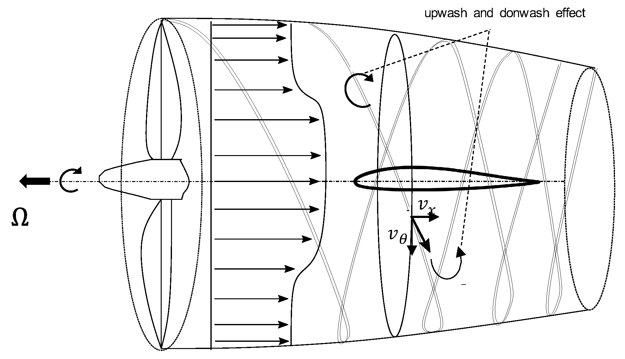
2.2. Propeller Modelling: Actuator Disk Boundary Condition

According to the general momentum theory, the freestream flow through the actuator disk is subjected to a static pressure jump and a tangential velocity jump. The non uniform load distribution, along with the radial direction of the disk, models the swirling flow. The flow model used in the BC is compressible and steady.
UZEN and SU2 [36] require the performance of the propeller as input data, expressed in terms of the dimensionless distributions of the derivatives of the thrust C T and power C P coefficient coefficients along with the non-dimensional local radius r ¯ of the disk shown in Figure 2.
To simulate the flowfield induced by a propeller in ANSYS-FLUENT, the available fan boundary condition is adopted. The fan BC takes as input performance the pressure jump and the tangential velocity profiles through the disk. Therefore, to give an input file with a standard format to the selected codes, equations for axial and angular momentum are here recalled:
S ρ r v θ v d S = Q
S Δ p d S = T
being ρ the freestream density, r the disk local radius (i.e., the disk radial coordinate starting from the centre of the hub), v the freestream velocity, and S the disk surface. Additionally, T and Q are the thrust and the torque forces induced by the propeller, v θ and Δ p are the tangential velocity component and the pressure jump. In this study, the normal velocity component is neglected. Using Renard’s relations [38], the forces and moments can be expressed in terms of non-dimensional coefficients, expressed in terms of the number of revolutions of the propeller in unit time, n, and the disk diameter, D:
C T = T ρ n 2 D 4
C Q = Q ρ n 2 D 5
C P = P ρ n 3 D 5
Finally, considering the relation between C P and C Q and introducing the advance ratio J:
C P = 2 π C Q
J = v n D
the pressure jump Δ p and the tangential velocity v θ can be expressed in terms of the torque and thrust derivatives with respect to the non-dimensional radial location:
Δ p ( r ) = a μ D R e M π r J 2 c d C T d r ¯
v θ ( r ) = a M D 2 2 π 4 J 2 r 2 d C P d r ¯
being a and μ the freestream speed of sound and dynamic viscosity, respectively. The relations in Equations (8) and (9) are used to write a UDF to load into ANSYS-FLUENT.

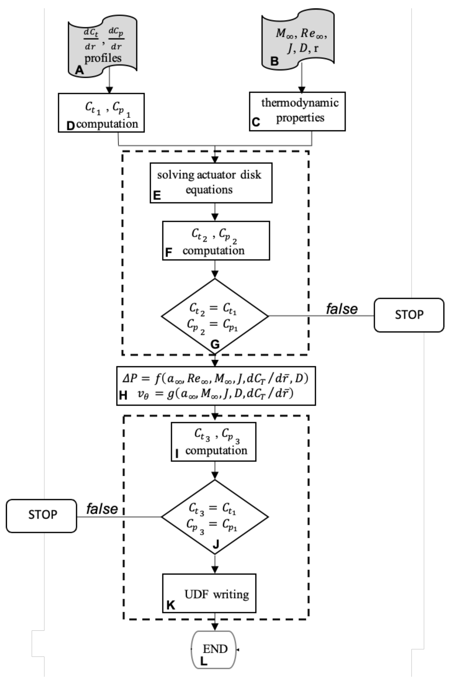
2.3. UDF Flowchart Description

A user-defined function is a function dynamically loaded within the ANSYS-FLUENT code which adds further proprietary computational tasks to the flow solver. The UDF implements and computes the propeller input BC according to Equations (8) and (9). The writing of the UDF is automated with a MATLAB script according to the flowchart shown in Figure 3, to adapt the UDF to the input conditions (inviscid or viscous simulation) of the problem considered.
The block A includes the actuator disk performance, read from an external file. Geometrical characteristics and fluid-dynamic properties (block B) are provided interactively by the user. Block C computes the thermodynamic properties according to the International Standard Atmosphere as an intersection point in the velocity-altitude plane between the Mach constant lines and Reynolds numbers provided in Block B.
The thrust and power coefficients are evaluated as integral values in the block D. This block performs additional consistency checks. The tangential velocity and pressure profiles along disk radius are obtained in block E, applying the Equations (8) and (9). A first check is performed in block G by comparing the thrust and power coefficients calculated in block D and the ones evaluated in block F. In case of failure, the procedure exists with an error.
Otherwise profiles obtained in block E are then interpolated with a 6-degree polynomial function in block H, and a further check is performed in blocks I and J. The UDF is written in block K if no errors occurred, additionally configuration files for UZEN and SU2 are also archived.

3. Code-to-Code Comparison: Analysed Test Cases

Two different test cases are considered, as shown in Figure 4. The isolated disk case is simulated to verify the correctness of the UDF procedure, by accounting for the propeller boundary condition in the CFD solvers.
The wing-propeller test case is analyzed to quantify the aerodynamic effect of DEP on the wing. The propeller and airfoil geometry, and the operating conditions are taken from the VENUS project [37].
Finally, it is worth to note that, although the simulated Mach number (i.e., M = 0.11 ) determines incompressible flow conditions, a density-based solver is adopted for all codes because the actuator disk BC available in SU2 and UZEN is developed for a compressible flow only.

4. Computational Set up of CFD Solvers

4.1. Freestream Conditions and Solution Approach

Numerical investigations are carried out by solving fully three-dimensional steady-state Eulerian equations for the isolated propeller case, and RANS equations for the wing-propeller interaction. The simulation of the propeller-wing interaction is assessed at R e = 1.7 × 10 6 and M = 0.11 , and for several angles of attack, namely α = 0 , 4 , and 8 . Standard sea-level atmospheric conditions are considered for the freestream flow.

4.2. Numerical Settings

Within RANS computations, the air is modelled according to the perfect gas model, with specific heat at constant pressure equal to c p = 1006 J/kgK and viscosity provided by the Sutherland law. Thermal conductivity is assumed constant, k = 0.0242 W/mK.
For SU2 and ANSYS-FLUENT solvers, ROE’s Flux Difference Splitting (FDS) with flux limiter [39], and second order upwind scheme [34] are adopted for convective discretization, respectively. The above set-up is assumed both for the isolated disk test case and for the propeller-wing test case (power-off). The resume of the numerical settings for convective discretizations is shown in Table 1.
Specifically, the ROE scheme is chosen for SU2 simulation, because the simulations performed with the JST central scheme available in SU2 (e.g., JST scheme [40]) evidenced instability of computation. To explain this behaviour, it is worth remarking that the actuator disk boundary condition models a discontinuity surface for pressure and tangential velocity. The steep change in flow properties due to momentum source creates numerical oscillations on some grid regions nearby the disk, which propagates instantaneously upstream and downstream, due to the low Mach. The dispersive nature of the truncation error of the central scheme amplifies such effect and the computation diverges [41]. As it is shown in Table 1, the wing-propeller interaction is simulated with a JST scheme with matrix dissipation [40]. This variant introduces artificial viscosity and makes the scheme close to an upwind-like scheme near flow discontinuity (i.e., the actuator disk) [42]. As several levels of grid refinements and, additional, tuning of 2nd viscosity coefficient ϵ 1 did not preserve the convergence of solution, the instability issue is addressed to the numerics and not to grid resolution.
On the other hand, ROE’s scheme, actually a second-order upwind scheme, acts by reducing spurious components of the solution. For the above-mentioned reason, the 2nd Order Upwind scheme is also adopted for ANSYS-FLUENT computation. Finally, it is worth noting that the upwind scheme used for DEP simulation, provided the best agreement with experimental results, see Ref. [5].
The convective fluxes in UZEN are discretized with the central JST scheme being the only available option. In this case, convergence is obtained only by assuming ϵ 1 = 3 , ϵ 2 = 0 , for 2nd and 4th viscosity coefficient. This choice is not in contradiction with previously mentioned issues, because the assumption of ϵ 2 = 0 makes the scheme first-order accurate. Therefore, higher order terms of truncation error, responsible for dispersive behaviour, are suppressed [40]. JST scheme in UZEN computations is used both for the isolated disk test case and for the propeller test case for both power-on and power-off conditions. A second-order weighted least square scheme is adopted for diffusive fluxes discretization, for all three codes considered.

4.3. Solution Methodology and Turbulence Closure

Compressible Navier–Stokes solver (density based) is adopted in UZEN to uniform the computation to SU2 because the available actuator disk boundary condition is implemented for the compressible case only [36].
Fully turbulent RANS solutions are performed for propeller-wing interaction. The k ω model with shear stress transport correction ( k ω SST) is used for wing-propeller simulations in SU2 and ANSYS-FLUENT.
The k ω TNT model is used in UZEN computation, being the only possible choice [35]. No wall functions are activated.

4.4. Convergence and Stability Criteria

Convergence of SU2 solution was enforced using two criteria: Cauchy criterion was applied over a span of more than 1000 iterations, with fluctuation amplitudes to be lower than 0.001 for drag and 0.01 for lift coefficient for converged results. Additionally, the reduction of density residual by five orders of magnitude was considered sufficient for a converged solution. A fixed Courant number equal to 4 was sufficient to ensure the stability of the computation while preserving the accuracy of the solution, and the speed of convergence.
For ANSYS-FLUENT and UZEN to assess convergence of numerical solution, both residuals, normal and axial aerodynamic coefficients (i.e., C N and C A ) have been monitored during iterations. Solution convergence has been assumed when residuals dropped more than three orders of magnitude, and the aerodynamic coefficients reached a constant value. Therefore, convergence is assessed by matching both criteria.

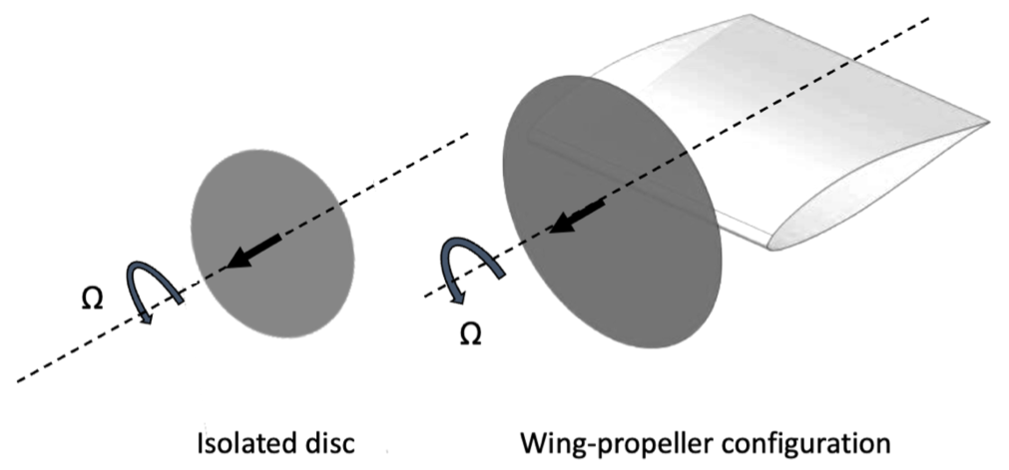
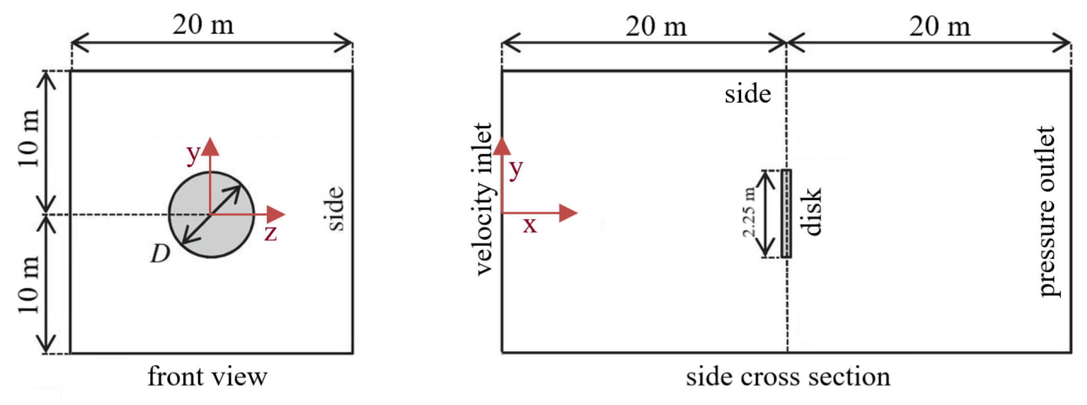
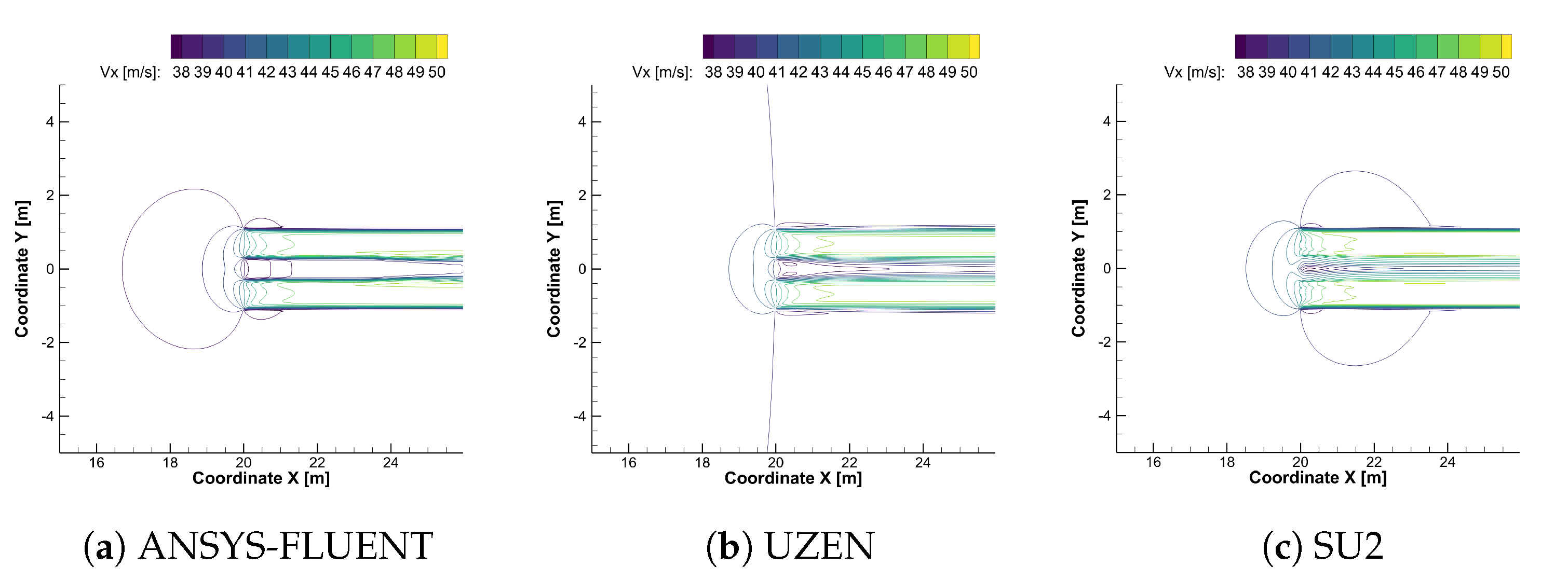
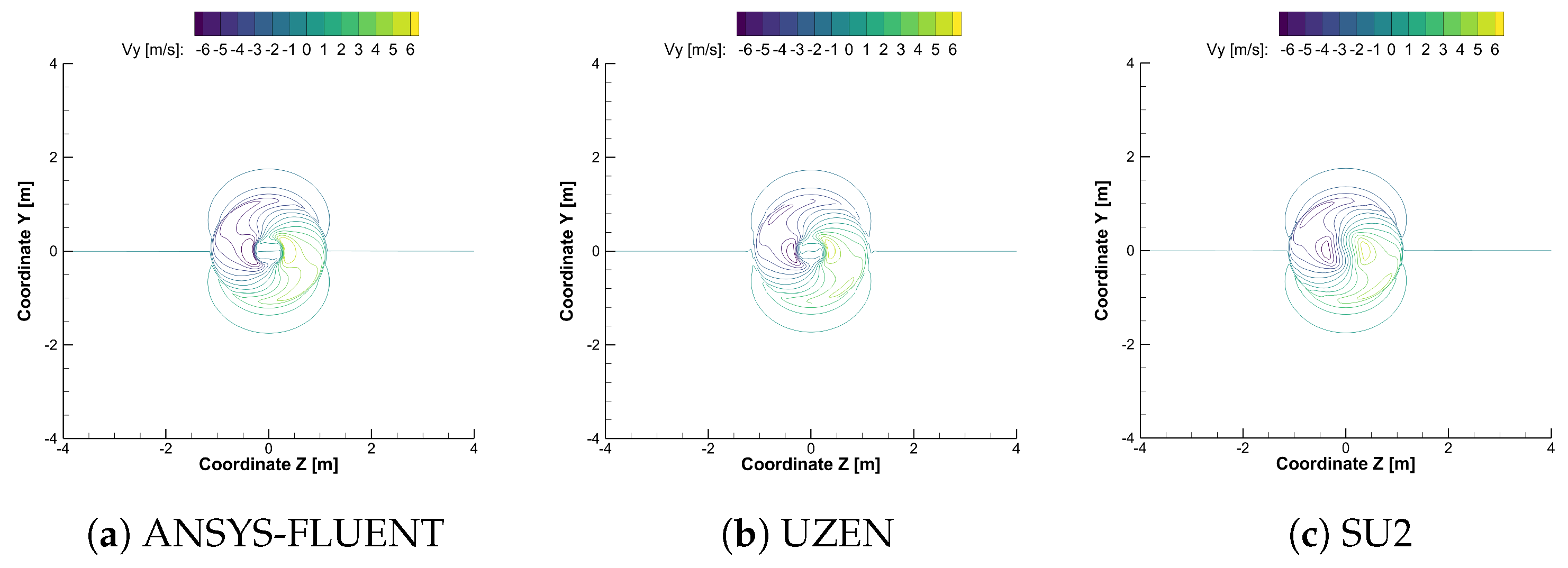
5. Isolated Propeller Test-Case

Geometry, Computational Domain and Boundary Conditions

Eulerian simulations on the isolated propeller are performed, to evaluate solution sensitivity to convective flux discretization among the considered flow solvers. In this computation, there is no nacelle modelled. Therefore, this simplified approach excludes relevant phenomena that are important when the wing is considered [15]. However, in the framework of a code-to-code comparison, and not of a design procedure, the above effect cannot, in the first instance, be considered.
The preliminary test case is representative of an isolated propeller in the free-stream domain, and it is shown in Figure 5. This test case is selected so that any interference, besides the domain itself, is avoided and, consequently, it allows verifying the implementation of the UDF in ANSYS-FLUENT and evaluating the agreement between the results of SU2, ANSYS-FLUENT, and UZEN. A computational multi-block domain by using structured hexahedral elements with a central O-grid is generated. The mesh counts 10 blocks and approximately 4.8 × 10 6 nodes. Grid converged solution is obtained for all three selected codes by using three levels of refinement, i.e., coarse (69,504 cells), medium (556,032 cells) and fine (4,448,256 cells). For the sake of simplicity, the grid convergence study is shown only for propeller-wing interaction test-case being more significant.
Input parameters are summarized in Table 2.
Figure 6 reports the x-velocity component in the plane z = 0 m for the three flow solvers. As it can be seen, the actuator disk increases the momentum and the energy of the flow, resulting in a velocity field that varies from the position of the actuator disk at x = 20 m up to the outflow. The hub effect is also visible, where there is no increase in momentum. The differences among solutions are present, mainly due to the adopted numerical scheme. The effect of artificial dissipation is highlighted in the comparison of normal velocity components in Figure 7, Figure 8 and Figure 9 at y = 20.05 m, 25 m, 30 m, respectively.
The comparisons show a good qualitative agreement among the results with ANSYS-FLUENT, UZEN and SU2 solvers. Specifically, at x = 20.05 m the best match among the three solutions is observed. Moving downstream from the disc, the effect of convective discretization is evidenced.
In Figure 8, it is shown that solutions computed with SU2 and ANSYS-FLUENT have similar normal velocity, as for both codes, a second order accurate discretization is adopted. On the other hand, the UZEN solution differs from the one computed by ANSYS-FLUENT and SU2 for the absence of the lobe-shaped pattern of normal velocity contours (see Figure 8). Recall that the UZEN solution is obtained by assuming ϵ 1 = 3 and ϵ 2 = 0 , to fix convergence problems. Therefore, convective discretization is first-order accurate, while solutions computed by ANSYS-FLUENT and SU2 are second-order accurate (see Table 1). The above mentioned observation suggests that smooth spatial gradients of flow solution computed with UZEN are suppressed.
Finally, in Figure 9, as the grid is coarsened, the difference of the UZEN solution is reduced. In flow regions immediately downstream of the disk, there is a pressure imbalance due to the hub, and the pressure perturbation that rises from the outlet and propagates upstream for the elliptical nature of the flow field. Recall that hub is not physically present in the geometry but was modelled with a source of zero velocity and pressure. Figure 10 shows the comparison of non-dimensional pressure at y = 0.6 m ( r / R = 0.53 ) among the different codes, where the profiles overlap each other, highlighting a perfect agreement.
Non-dimensional stream-wise velocity component is compared in Figure 11 at the same location.
SU2 and UZEN solution show a pressure difference at the outlet of about 20 Pa, which, at sea level conditions, can be considered negligible. Furthermore, also a vanishing difference for velocity computed with the two codes is observed, and is due to the different atmosphere models implemented in UZEN. The agreement between SU2 and UZEN is explained considering that the same numerical discretization for convective terms is exploited (i.e., JST scheme), and the same kind of boundary condition. ANSYS-FLUENT predicts a higher velocity that is explained by considering the different discretization schemes used (ANSYS-FLUENT does not support the JST scheme, rather a second-order upwind scheme is used for convection). As the inlet condition is the same and the FLUENT boundary condition is implemented as a source term, to ensure mass conservation, in incompressible regime, a higher velocity at the outlet, which balances the numerical diffusion, is observed.

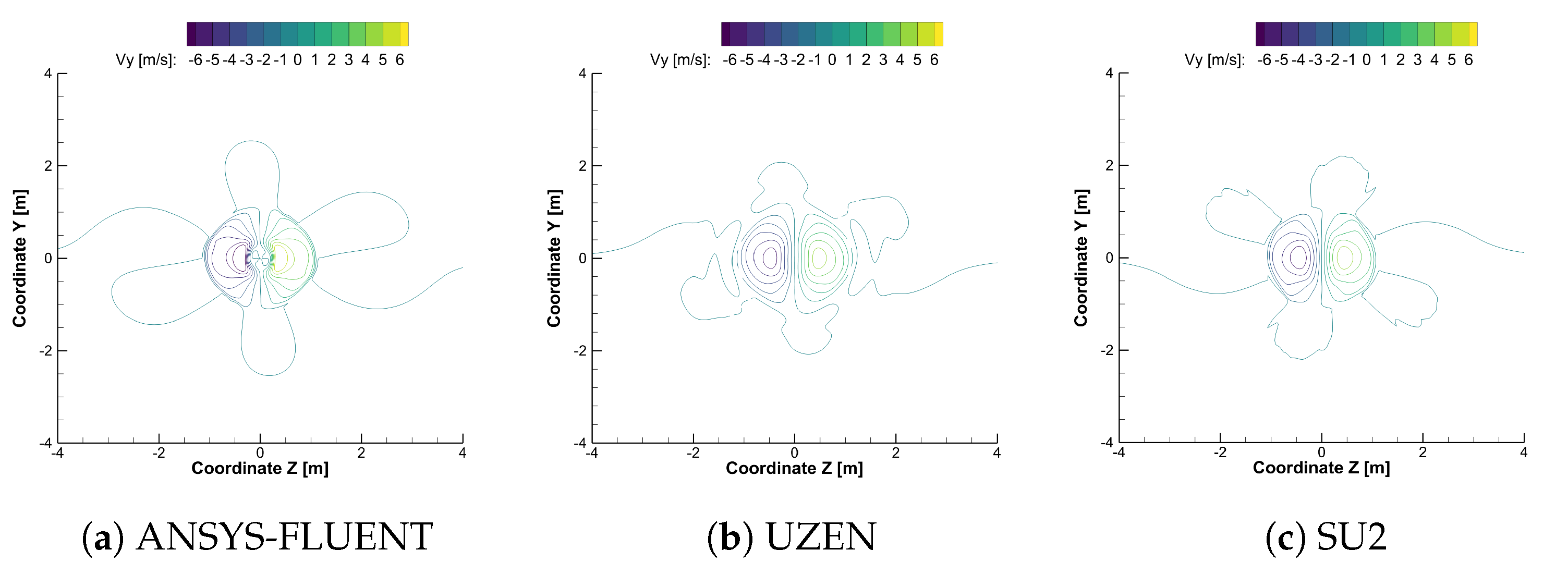
6. Propeller-Wing Interaction Test-Case

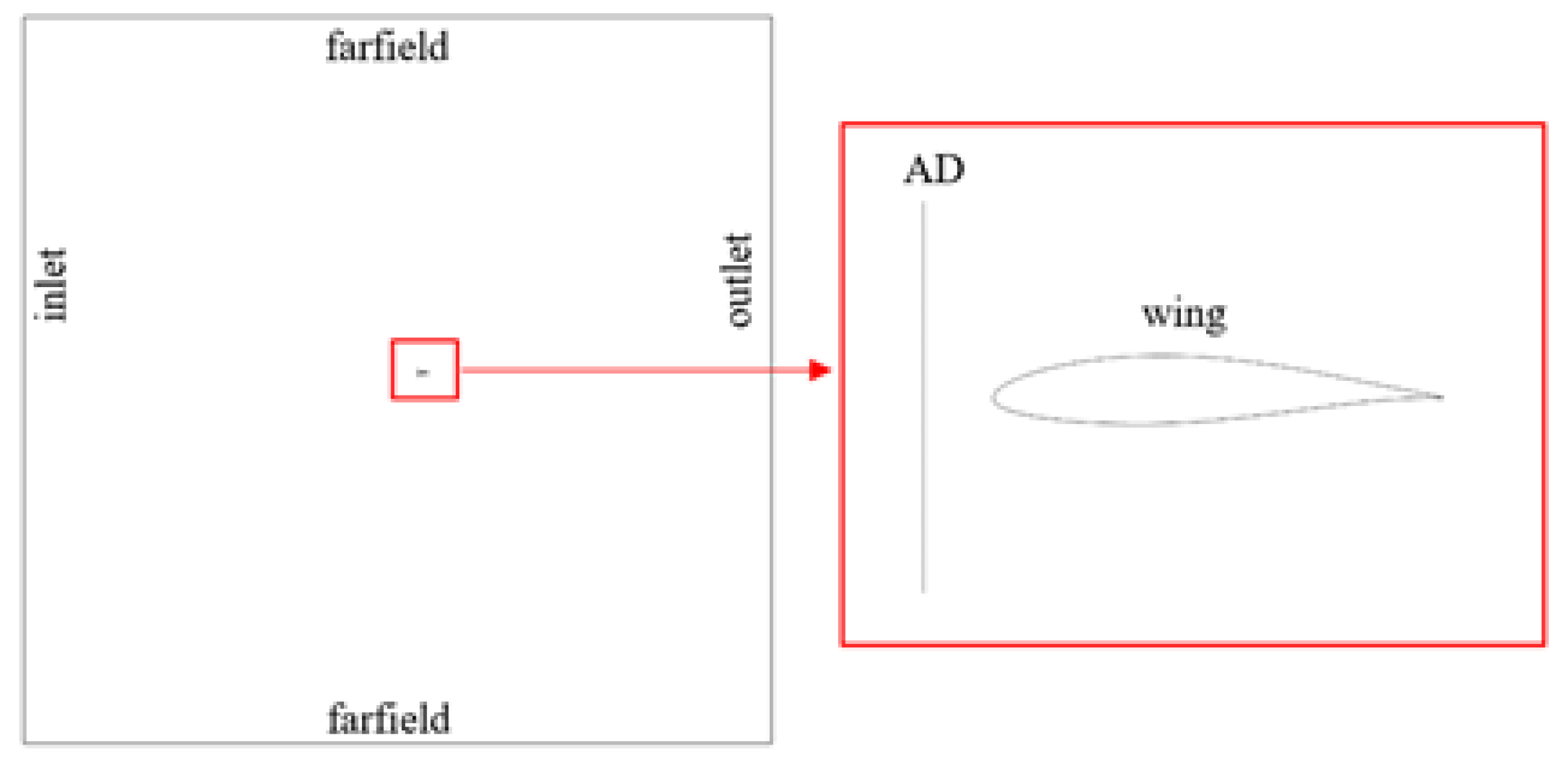
6.1. Geometry, Computational Domain and Boundary Conditions

To simulate a DEP configuration, a single actuator disk is placed in front of a finite wingspan wing, applying periodic boundary conditions on the side walls of the computational domain. Power-off and power-on conditions are compared to evaluate the effects of the propeller. The flow conditions and actuator disk characteristics are reported in Table 3. Three angles of attack, namely α = 0 , 4 and 8 , are investigated.
The computational domain is made of a multi-block structured mesh consisting of 57 blocks and 5 × 10 6 cells on the finest level, approximately. The structured grid is mandatory for the UZEN code, while for SU2 and ANSYS-FLUENT, it was converted to unstructured type, accordingly. Figure 12 depicts the computational domain and the location of the actuator disk (AD) and the airfoil.
Figure 13 shows some details of the computational mesh on the airfoil, actuator disk, and side plane.

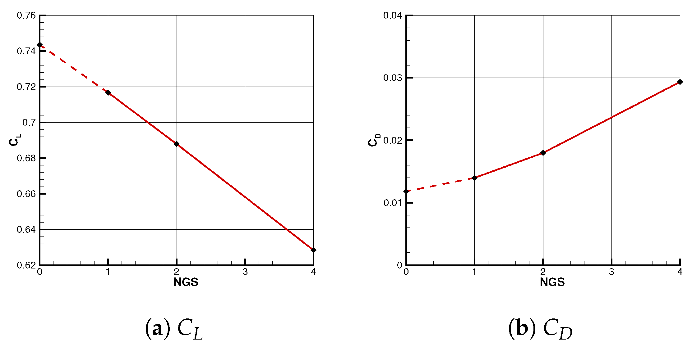
6.2. Grid Convergence Study

To assess the accuracy of the computational mesh, a grid convergence analysis using the Richardson extrapolation method is adopted [43]. The refinement ratio h is computed as the cubic root of the cells’ number ratio between the fine and medium grid level, h 2 = N f i n e N m e d i u m 1 / 3 . The apparent order of the method for the lift coefficient is computed as p ( C L ) = 1 ln ( h 2 / h 1 ) ln C L f i n e C L m e d i u m C L m e d i u m C L c o a r s e . Results of the grid convergence study are reported for the power-off condition in Table 4 and Figure 14, in details p ( C L ) = 1.05 and p ( C D ) = 1.51 .
Here for the sake of brevity, the grid convergence is here reported for the UZEN computations only. Recall that the computational mesh is the same for all the CFD solvers. Here the study is conducted with the UZEN flow solver as its solution represents the computation obtained with a scheme with higher artificial viscosity, as previously stated (see Section 4.2).

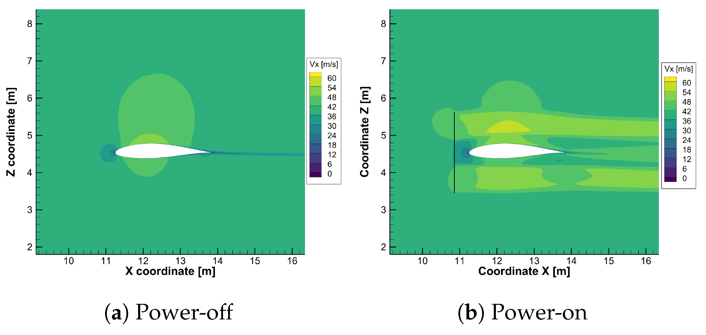
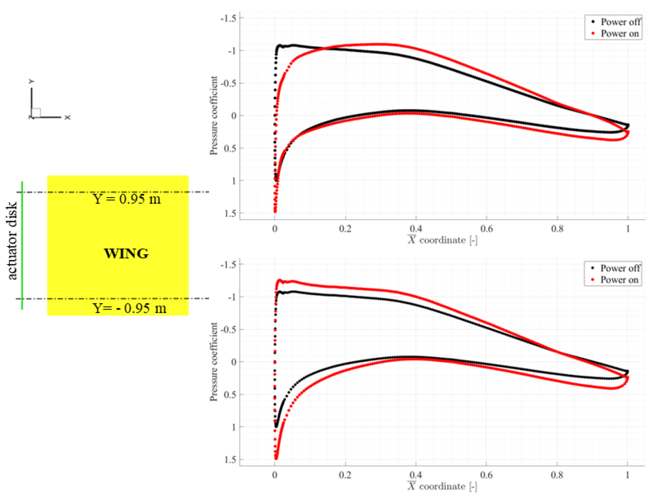
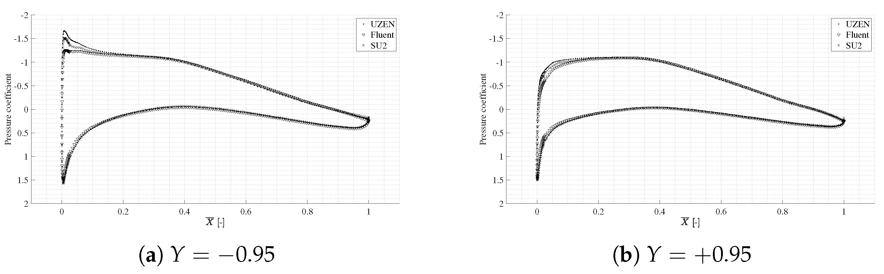
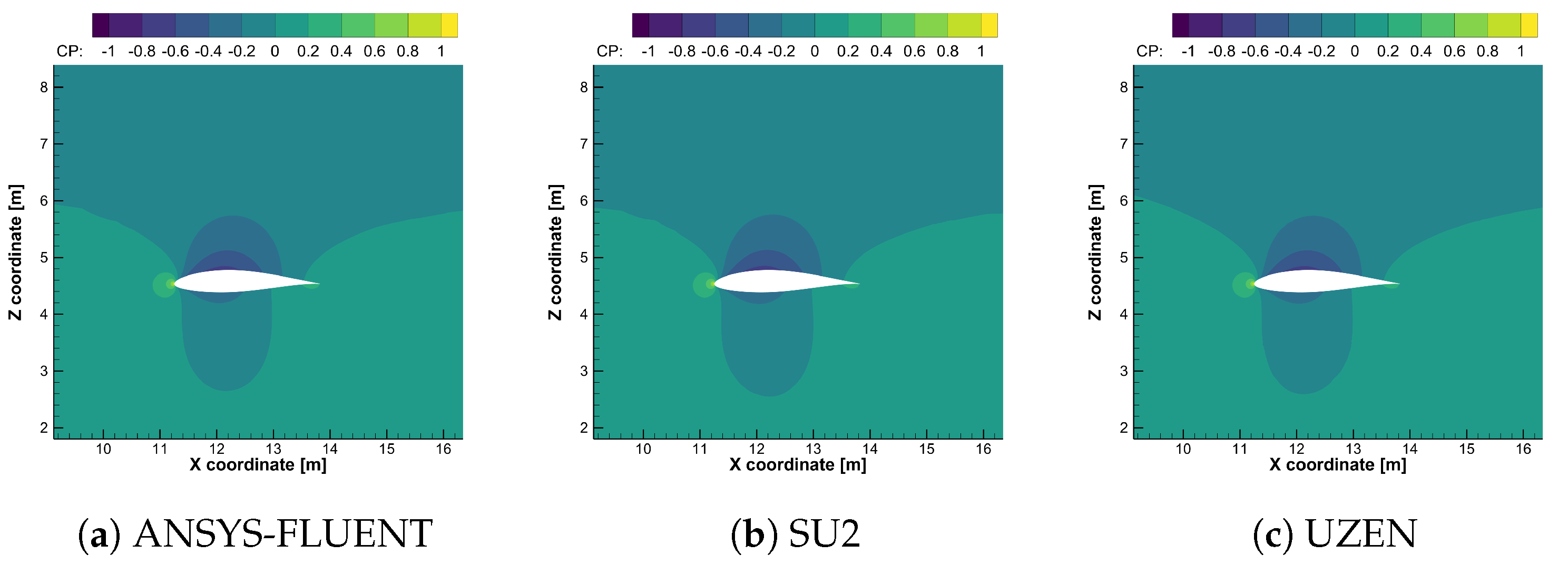
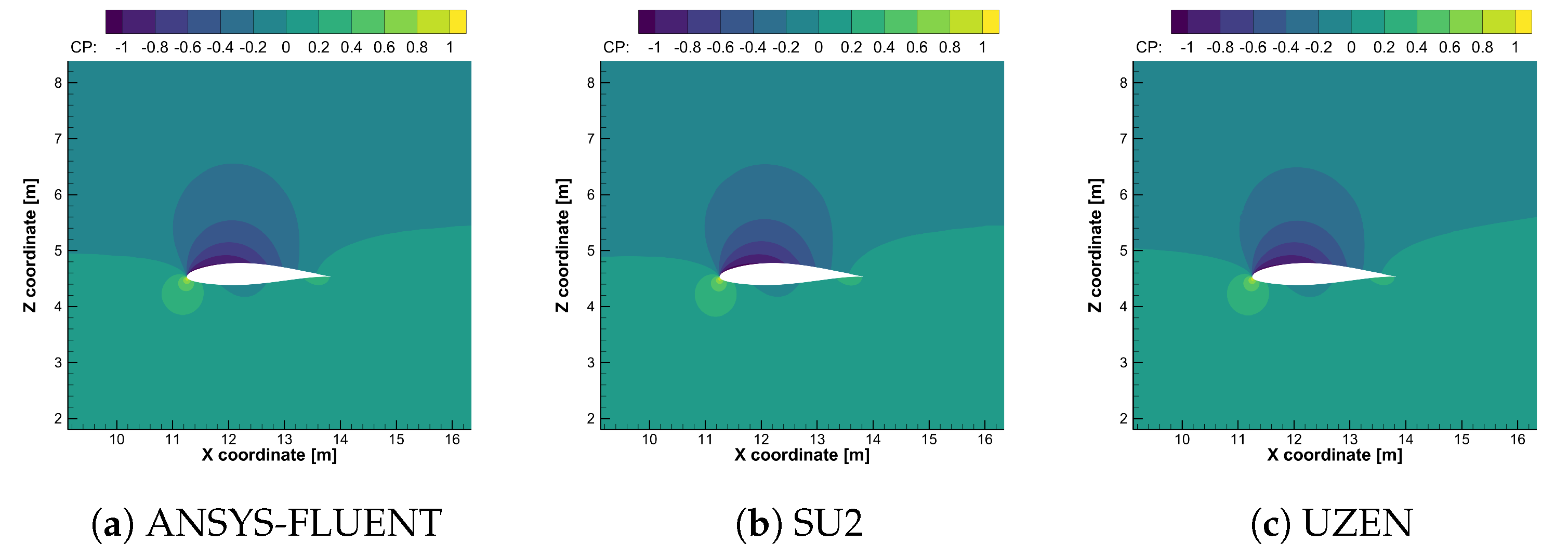
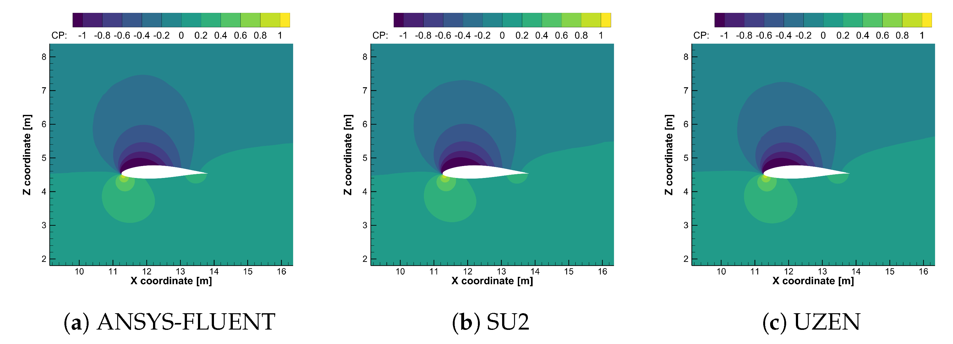
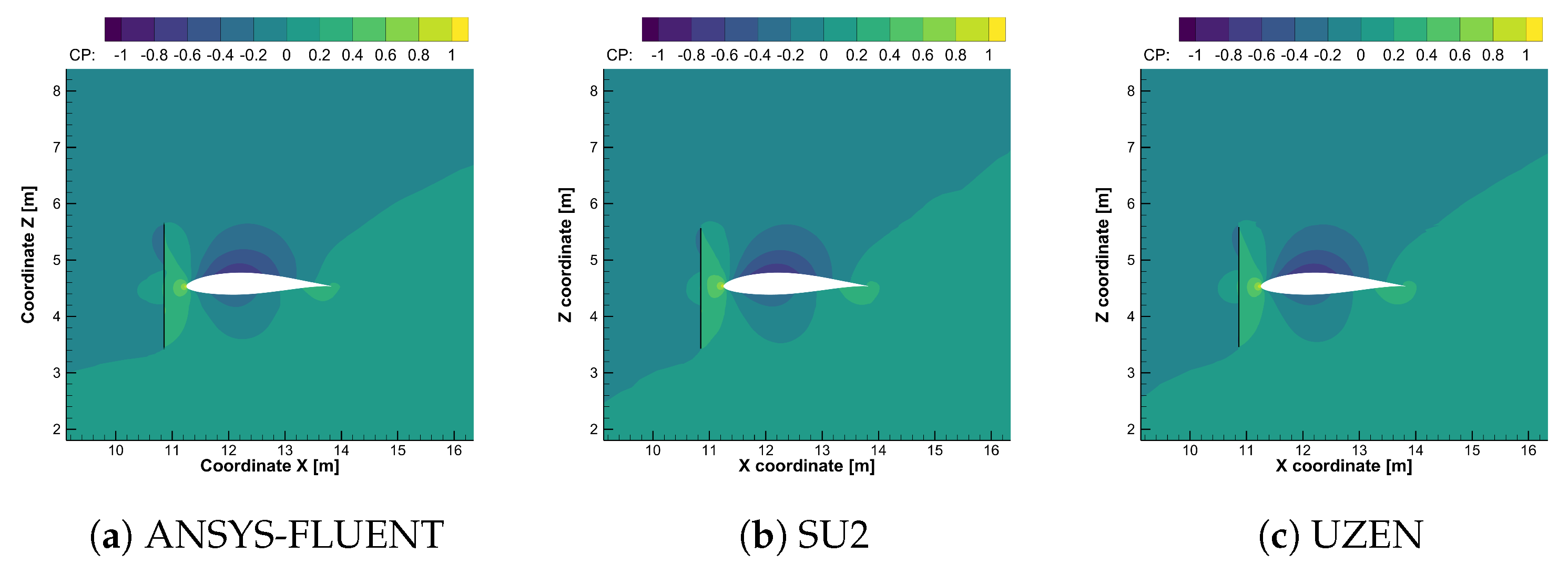
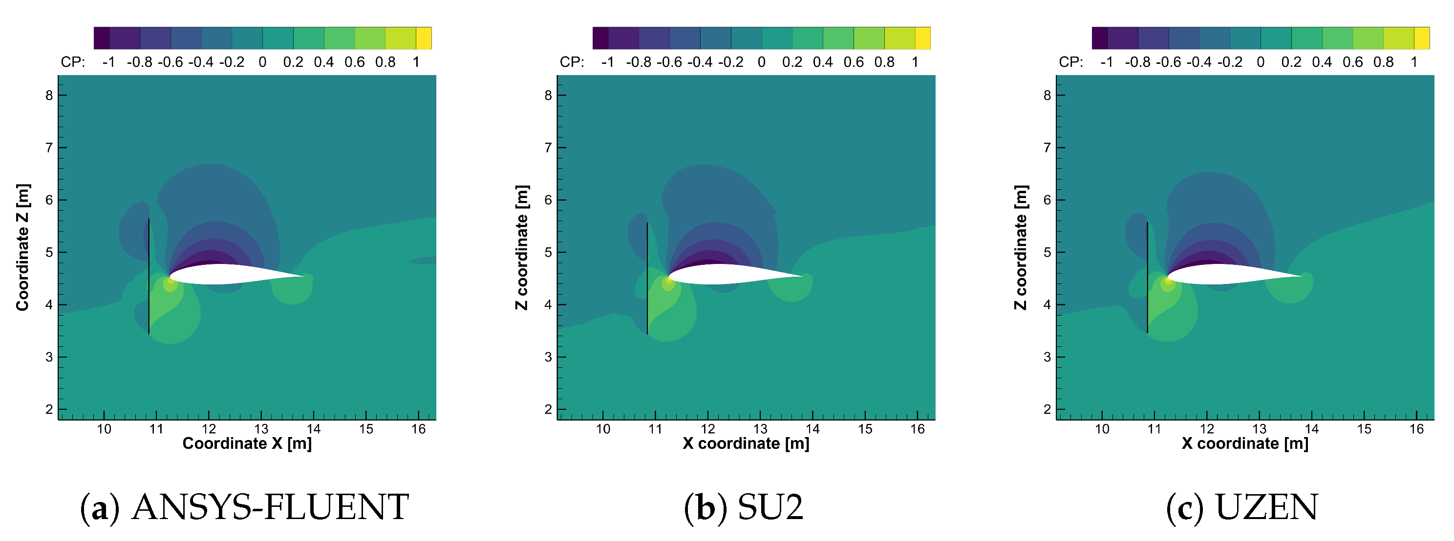
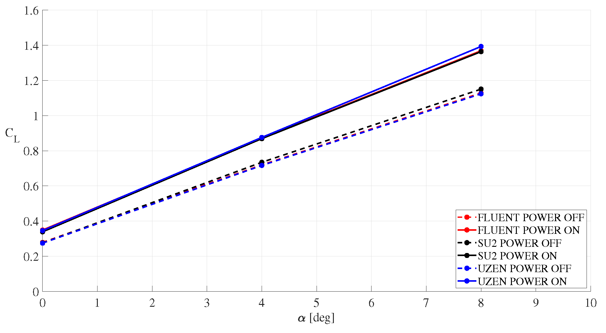
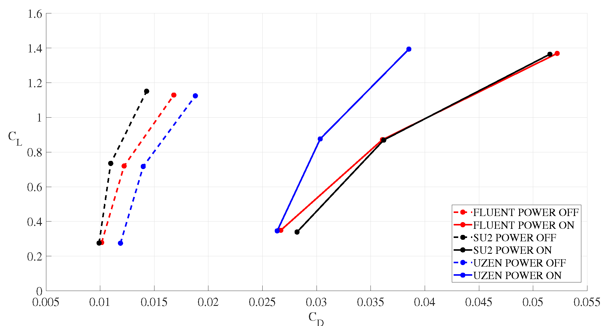
6.3. Computational Results for the Propeller-Wing Interaction

As far as results are concerned, Figure 15 shows the effect of the propeller on the streamwise velocity component near the airfoil in the central section of the wing.
The presence of the propeller affects the momentum downstream of the disk location and, in detail, outside the hub region where no effect is induced. The influence on pressure coefficient can be appreciated in Figure 16, where two sections are compared at y = ± 0.95 m. Two effects are evidenced, the first one regards the increase in dynamic pressure induced by the propeller, stated by the augmented value of the pressure coefficient at the stagnation point. The second effect is related to the induced AoA that varies along with the wing, thus, providing a different spanwise pressure distribution, see Figure 16.
A code-to-code comparison on the pressure coefficient distribution is shown in Figure 17 for the same spanwise sections. There is an overall good agreement among the codes, with appreciable differences in the expansion region near the hub. These discrepancies among the CFD results are confirmed by performing a sensitivity analysis on grid resolution. One explanation of the above differences is related to the different hub modelling in the codes, i.e., boundary condition. Specifically, ANSYS-FLUENT allows one to specify the hub position in the fan boundary condition (fan dialogue box). While in the SU2 and UZEN codes, the HUB position (fan hub ratio) is derived from geometry.
Figure 18, Figure 19 and Figure 20 show the pressure coefficient contour for the three angles of attack in the mid-section. The computed flowfield is in agreement among the codes. The same comparison is available with the propeller in the power-on condition in Figure 21, Figure 22 and Figure 23. No particular discrepancies are observed for the power-off condition of the propeller (see Figure 18, Figure 19 and Figure 20). On the other hand, in power-on condition, the solution with the three codes differs close to the expansion region, and in the downstream wake respectively (see Figure 21, Figure 22 and Figure 23). First, the Hub effect, as previously specified, explains the difference in the expansion regions and is amplified by increasing the angle of attack. Additionally, the ANSYS-FLUENT solution shows a not fully developed wake if compared to the UZEN and SU2 solutions. This effect is visible at A o A = 8 and is explained by considering the higher numerical dissipation of upwind discretization.
The effect of the propeller on the wing performance can be observed in Figure 24 and Figure 25. The computed lift coefficient, see Figure 24, matches at all angles of attack, both in power off and power on conditions. The primary effect of the propeller is to increase the lift coefficient value from the corresponding power-off value; a secondary effect is that the slope of the lift curve is different, being greater for the power on the lift curve. The drag coefficient presents major differences for all the conditions, as shown in Figure 25. In power-off condition, flow solvers provide different drag coefficient values with a maximum difference up to Δ C D = 50 counts, with SU2 predicting the lowest polar curve and UZEN the highest. These differences may be ascribed to several reasons, among which are the different turbulent closures, and the different schemes used for convection. Power-off solutions show greater sensitivity to the selected numerical scheme.
Recall that UZEN solutions (power-on/power-off) are obtained assuming for the 2nd and 4th order viscosity coefficients, ϵ 1 = 3 and ϵ 2 = 0 , respectively. Fourth-order dissipation is not active ( ϵ 2 = 0 ), being unnecessary for steady simulations. The second-order dissipation behaves as a limiter function in presence of strong discontinuities of flow domain.
In the present case, the disk behaves as a discontinuity surface, and low-frequency gradients are smoothed, assuming ϵ 1 = 3 . Therefore, the convective scheme used in UZEN acts as a first order upwind, while ANSYS-FLUENT and SU2 rely on a second-order accurate scheme, thus showing a lower artificial diffusion in power-off conditions.
When the power-on condition is simulated, the dynamic pressure and turbulent kinetic energy of the flow increase. In this condition, the sensitivity of the turbulence model seems to prevail. In fact, ANSYS-FLUENT and SU2 have the same drag polar, while UZEN, which relies on a TNT k- ω model, computes a lower drag coefficient. In the case of the power-on condition, the drag coefficient increases with respect to power-off and, in particular, at α = 4 and 8 ANSYS-FLUENT and SU2 compute a similar C D , whereas a better agreement is found at α = 0 between Fluent and UZEN. Noteworthy, the trend in drag polar for power on condition is the opposite of power off, as UZEN predicts the lowest drag values.

7. Conclusions

The paper dealt with a flowfield analysis of the effect of a rotating propeller installed on a wing representative of a distributed electric propulsion system, performed with cross-comparison study among different CFD solvers, namely SU2, UZEN, and ANSYS-FLUENT. Steady RANS simulations were carried out at R e = 1.7 × 10 6 and M = 0.11 and at different flow attitudes. The propeller was modelled as an actuator disk according to the general momentum theory and was accounted for in the flow solvers as a boundary condition, for the momentum and energy equations. An in-house procedure was developed that automatically provides the propeller thrust and torque distributions to set the boundary condition in a unified format for the three flow solvers. A preliminary test case was performed using an isolated propeller to evaluate possible discrepancies in the results due to the actuator disk model. The procedure was then tested on a propeller mounted upstream on a finite straight wing span, and simulations were performed at α = 0 , 4 , and 8 . Comparisons among the numerical results of the three flow solvers are satisfactory despite the different flowfield discretizations and numerics of the codes. Both the isolated propeller test case and wing-propeller test case evidenced that second-order upwind schemes allow one to obtain stability, and convergence of solution for low-Mach number simulation. The stabilizing contribution of upwind schemes was found to be effective when the propeller is modelled as a boundary condition in CFD solvers. On the other hand, second-order accurate central schemes were shown to produce unstable computation. The three CFD solvers correctly described the primary effect of the propeller, that is, to increase the lift coefficient value from the corresponding power-off value. A secondary effect is that the slope of the lift curve is changed, being greater for the power on the lift curve. The drag coefficient presents major differences for all the conditions. For instance, in power off condition, the flow solvers provide different drag coefficient values with a maximum difference up to Δ C D = 50 counts, with SU2 predicting the lowest polar curve and UZEN the highest. These differences were ascribed to the different turbulent closure model. In case of power on condition, the drag coefficient increases with respect to power off and, in particular, at α = 4 and 8 Fluent and SU2 compute a similar C D , whereas a better agreement is found at α = 0 between Fluent and UZEN. Noteworthy, the trend in drag polar for power on condition is the opposite of power off, as UZEN predicts the lowest drag values. Finally, the promising comparisons among the three flow solvers suggest the possibility of extending the developed procedure to other different solvers to support design activities of distributed electric propulsion systems.

Author Contributions

Conceptualization, G.P. and D.d.R.; methodology and software, O.R., G.P., A.A. and D.d.R.; validation, O.R., G.P. and A.A.; formal analysis, G.P. and A.A.; resources, A.V.; data curation, O.R. and D.d.R.; writing, A.A., G.P. and D.d.R.; writing and editing, G.P., O.R. and D.d.R.; review, A.V.; supervision, G.P. All authors have read and agreed to the published version of the manuscript.

Funding

This research received no external funding.

Data Availability Statement

Research data are restricted due to CIRA policy regulation.

Acknowledgments

This research work was carried out in the framework of the European research project VENUS (inVestigation of distributEd propulsion Noise and its mitigation through wind tUnnel experiments and numerical Simulations), a H2020/CleanSky JU thematic topic [37]. The VENUS project aims at understanding the physics behind the aeroacoustics of DEP through a deep theoretical, experimental and numerical study. The consortium is developing methods and tools to support a concurrent aerodynamic and aeroacoustic design of DEP configuration aircraft. As a practical achievement, the project is supporting the design of a new regional aircraft configuration, in terms of wing and engines installation, to target a DEP which is optimized in terms of aerodynamic and aeroacoustic performance [37].

Conflicts of Interest

The authors declare no conflict of interest.

References

  1. Lee, D.S.; Fahey, D.W.; Forster, P.M.; Newton, P.J.; Wit, R.C.; Lim, L.L.; Owen, B.; Sausen, R. Aviation and global climate change in the 21st century. Atmos. Environ. 2009, 43, 3520–3537. [Google Scholar] [CrossRef] [PubMed] [Green Version]
  2. Sehra, A.K.; Whitlow, W. Propulsion and power for 21st century aviation. Prog. Aerosp. Sci. 2004, 40, 199–235. [Google Scholar] [CrossRef]
  3. Stoll, A.M.; Bevirt, J.; Moore, M.D.; Fredericks, W.J.; Borer, N.K. Drag Reduction Through Distributed Electric Propulsion. In Proceedings of the 14th AIAA Aviation Technology, Integration, and Operations Conference, Atlanta, GA, USA, 16–20 June 2014. [Google Scholar] [CrossRef] [Green Version]
  4. Patterson, M.D.; German, B. Conceptual Design of Electric Aircraft with Distributed Propellers: Multidisciplinary Analysis Needs and Aerodynamic Modeling Development. In Proceedings of the 52nd Aerospace Sciences Meeting, National Harbor, MD, USA, 13–17 January 2014. [Google Scholar] [CrossRef]
  5. van Arnhem, N.; de Vries, R.; Sinnige, T.; Vos, R.; Eitelberg, G.; Veldhuis, L.L.M. Engineering Method to Estimate the Blade Loading of Propellers in Nonuniform Flow. AIAA J. 2020, 58, 5332–5346. [Google Scholar] [CrossRef]
  6. Deere, K.A.; Viken, S.A.; Carter, M.B.; Viken, J.K.; Derlaga, J.M.; Stoll, A.M. Comparison of High-Fidelity Computational Tools for Wing Design of a Distributed Electric Propulsion Aircraft. In Proceedings of the 35th AIAA Applied Aerodynamics Conference, AIAA, Denver, CO, USA, 5–9 June 2017. [Google Scholar] [CrossRef] [Green Version]
  7. Antcliff, K.R.; Capristan, F.M. Conceptual Design of the Parallel Electric- Gas Architecture with Synergistic Utilization Scheme (PEGASUS) Concept. In Proceedings of the 18th AIAA/ISSMO Multidisciplinary Analysis and Optimization Conference, Denver, CO, USA, 5–9 June 2017. [Google Scholar] [CrossRef] [Green Version]
  8. Snyder, M.H.; Zumwalt, G.W. Effects of wingtip-mounted propellers on wing lift and induced drag. J. Aircr. 1969, 6, 392–397. [Google Scholar] [CrossRef]
  9. Sinnige, T.; van Arnhem, N.; Stokkermans, T.C.A.; Eitelberg, G.; Veldhuis, L.L.M. Wingtip-Mounted Propellers: Aerodynamic Analysis of Interaction Effects and Comparison with Conventional Layout. J. Aircr. 2019, 56, 295–312. [Google Scholar] [CrossRef] [Green Version]
  10. Veldhuis, L. Propeller Wing Aerodynamic Interference. Ph.D. Thesis, Delft University of Technology, Delft, The Netherlands, 2005. [Google Scholar]
  11. Gallani, M.A.; Goes, L.C.S.; Nerosky Luiz, A.R. Effects of distributed electric propulsion on the performance of a general aviation aircraft. In Proceedings of the 2020 AIAA/IEEE Electric Aircraft Technologies Symposium (EATS), New Orleans, LA, USA, 26–28 August 2020. [Google Scholar]
  12. Rubin, R.L.; Zhao, D. New Development of Classical Actuator Disk Model for Propellers at Incidence. AIAA J. 2021, 59, 1040–1054. [Google Scholar] [CrossRef]
  13. Kroo, I. Propeller-wing integration for minimum induced loss. J. Aircr. 1986, 23, 561–565. [Google Scholar] [CrossRef]
  14. Miranda, L.; Brennan, J. Aerodynamic effects of wingtip-mounted propellers and turbines. In Proceedings of the 4th Applied Aerodynamics Conference, San Diego, CA, USA, 9–11 June 1986. [Google Scholar] [CrossRef]
  15. Beckers, M.F.; Schollenberger, M.; Lutz, T.; Bongen, D.; Radespiel, R.; Florenciano, J.L.; Funes-Sebastian, D.E. CFD Investigation of High-Lift Propeller Positions for a Distributed Propulsion System. In Proceedings of the AIAA AVIATION 2022 Forum, Chicago, IL, USA, 27 June–1 July 2022. [Google Scholar] [CrossRef]
  16. Patternson, J.J.; Bartlett, G.R. Evaluation of Installed Performance of a Wing-Tip-Mounted Pusher Turboprop on a Semispan Wing; NASA TP-2739; NASA: Washington, DC, USA, 1978. [Google Scholar]
  17. Kim, H.D.; Perry, A.T.; Ansell, P.J. A Review of Distributed Electric Propulsion Concepts for Air Vehicle Technology. In Proceedings of the 2018 AIAA/IEEE Electric Aircraft Technologies Symposium, AIAA 2018-4998, Cincinnati, OH, USA, 12–14 July 2018. [Google Scholar] [CrossRef] [Green Version]
  18. Borer, N.K.; Patterson, M.D.; Viken, J.K.; Moore, M.D.; Bevirt, J.; Stoll, A.M.; Gibson, A.R. Design and Performance of the NASA SCEPTOR Distributed Electric Propulsion Flight Demonstrator. In Proceedings of the 16th AIAA Aviation Technology, Integration, and Operations Conference, Washington, DC, USA, 13–17 June 2016. [Google Scholar] [CrossRef] [Green Version]
  19. NASA. NASA X-57 Maxwell. 2016. Available online: https://www.nasa.gov/press-release/nasa-electric-research-plane-gets-x-number-new-name (accessed on 25 November 2022).
  20. Patterson, M.D.; Derlaga, J.M.; Borer, N.K. High-Lift Propeller System Configuration Selection for NASA’s SCEPTOR Distributed Electric Propulsion Flight Demonstrator. In Proceedings of the 16th AIAA Aviation Technology, Integration, and Operations Conference, Washington, DC, USA, 13–17 June 2016. [Google Scholar] [CrossRef]
  21. Rankine, W.M.J. On the Mechanical Principles of the Action of Propellers. Trans. Inst. Nav. Archit. 1865, 6, 13–39. [Google Scholar]
  22. Froude, R. On the Part Played in Propulsion by Differences of Fluid Pressure. Trans. Inst. Nav. Archit. 1865, 30, 390–405. [Google Scholar]
  23. Dommasch, D. Elements of Propeller and Helicopter Aerodynamics; Pitman Aeronautical Publications; Pitman Publishing Corporation: New York, NY, USA, 1953. [Google Scholar]
  24. Witkowski, D.P.; Lee, A.K.H.; Sullivan, J.P. Aerodynamic interaction between propellers and wings. J. Aircr. 1989, 26, 829–836. [Google Scholar] [CrossRef]
  25. Alba, C.; Elham, A.; German, B.J.; Veldhuis, L.L.M. A surrogate- based multi-disciplinary design optimization framework modeling wing-propeller interaction. Aerosp. Sci. Technol. 2018, 78, 721–733. [Google Scholar] [CrossRef]
  26. Hwang, J.T.; Ning, A. Large-scale multidisciplinary optimization of an electric aircraft for on-demand mobility. In Proceedings of the 2018 AIAA/ASCE/AHS/ASC Structures, Structural Dynamics, and Materials Conference, AIAA-2018-1384, Kissimmee, FL, USA, 8–12 January 2018. [Google Scholar] [CrossRef] [Green Version]
  27. Stokkermans, T.C.; van Arnhem, N.; Sinnige, T.; Veldhuis, L.L.M. Validation and Comparison of RANS Propeller Modeling Methods for Tip-Mounted Applications. AIAA J. 2018, 57, 566–580. [Google Scholar] [CrossRef]
  28. Moens, F.; Gardarein, P.; Mikkelsen, R. Numerical Simulation of the Propeller/Wing Interactions for Transport Aircraft. In Proceedings of the 19th AIAA Applied Aerodynamics Conference, Anaheim, CA, USA, 11–14 June 2001; Volume 57. [Google Scholar] [CrossRef]
  29. Troldborg, N. Actuator Line Modeling of Wind Turbine Wakes. Ph.D. Thesis, Delft University of Technology, Delft, The Netherlands, 2009. [Google Scholar]
  30. Zhang, T.; Higgins, R.J.; Qiao, G.; Barakos, G.N. Optimization of Distributed Propulsion Using CFD. In Proceedings of the AIAA AVIATION 2022 Forum, Chicago, IL, USA, 27 June–1 July 2022. [Google Scholar] [CrossRef]
  31. Chauhan, S.S.; Martins, J.R.R.A. RANS-Based Aerodynamic Shape Optimization of a Wing Considering Propeller–Wing Interaction. J. Aircr. 2021, 58, 497–513. [Google Scholar] [CrossRef]
  32. Palacios, F.; Alonso, J.; Duraisamy, K.; Colonno, M.; Hicken, J.; Aranake, A.; Campos, A.; Copeland, S.; Economon, T.; Lonkar, A.; et al. Stanford University Unstructured (SU⌃2): An open-source integrated computational environment for multi-physics simulation and design. In Proceedings of the 51st AIAA Aerospace Sciences Meeting including the New Horizons Forum and Aerospace Exposition, Grapevine, TX, USA, 7–10 January 2013; American Institute of Aeronautics and Astronautics: Reston, VA, USA, 2013. [Google Scholar] [CrossRef] [Green Version]
  33. Marongiu, C.; Catalano, P.; Amato, M.; Iaccarino, G. U-ZEN: A Computational Tool Solving U-Rans Equations for Industrial Unsteady Applications. In Proceedings of the 34th AIAA Fluid Dynamics Conference and Exhibit, Portland, OR, USA, 28 June–1 July 2004; American Institute of Aeronautics and Astronautics (AIAA): Reston, VA, USA, 2004. [Google Scholar] [CrossRef]
  34. ANSYS Academic Research Release 18.1, Help System, Fluent; Ansys, Inc.: Canonsburg, PA, USA, 2018.
  35. Amato, M.; Paparone, L.; Catalano, P.; Puoti, V. ZEN FLOW SOLVER—Zonal Euler Navier-Stokes Flow Solver USER GUIDE; Technical Report CIRA-UM-AEP-99-054; CIRA—Centro Italiano Ricerche Aerospaziali: Capua, Italy, 1999. [Google Scholar]
  36. Saetta, E.; Russo, L.; Tognaccini, R. Implementation and validation of a new actuator disk model in SU2. In Proceedings of the SU2 Conference 2020, Virtual Event, 10–12 June 2020. [Google Scholar]
  37. Available online: https://cordis.europa.eu/project/id/886019 (accessed on 25 July 2021).
  38. Glauert, H. Airplane Propellers. In Aerodynamic Theory; Durand, W.F., Ed.; Springer: Berlin/Heidelberg, Germany, 1935; Volume IV, pp. 169–360. [Google Scholar]
  39. Musa, O.; Guoping, H.; Zonghan, Y.; Qian, L. An improved Roe solver for high order reconstruction schemes. Comput. Fluids 2020, 207, 104591. [Google Scholar] [CrossRef]
  40. Jameson, A. Origins and further development of the Jameson-Smith-Turkel scheme. AIAA J. 2017, 55, 1487–1510. [Google Scholar] [CrossRef]
  41. Hirsh, C. Numerical Computation of Internal and External Flow; Elsevier: Amsterdam, The Netherlands, 2007. [Google Scholar]
  42. Swanson, R.C.; Radespiel, R.; Turkel, E. Comparison of Several Dissipation Algorithms for Central Difference Schem; NASA Contract No. NAS1-19480; NASA: Washington, DC, USA, 1997. [Google Scholar]
  43. Roache, P.J. Quantification of uncertainty in computational fluid dynamics. Annu. Rev. Fluid Mech. 1997, 29, 123–160. [Google Scholar] [CrossRef]
Figure 1. Schematic of a wing-tip (tractor) propeller and downstream effects on airfoil.
Aerospace 10 00064 g001
Figure 2. Dimensionless thrust (solid line) and power (dashed line) derivatives distribution along with the non-dimensional radius.
Aerospace 10 00064 g002
Figure 3. Flowchart diagram to write the UDF.
Aerospace 10 00064 g003
Figure 4. Pictorial view of the simulated test cases.
Aerospace 10 00064 g004
Figure 5. Isolated propeller and computational domain.
Aerospace 10 00064 g005
Figure 6. Comparison of x component velocity at section z = 0 m.
Aerospace 10 00064 g006
Figure 7. Comparison of y component velocity at section x = 20.05 m.
Aerospace 10 00064 g007
Figure 8. Comparison of y component velocity at section x = 25 m.
Aerospace 10 00064 g008
Figure 9. Comparison of y component velocity at section x = 30 m.
Aerospace 10 00064 g009
Figure 10. Pressure profile along streamline y = 0.6 m at z = 0 m section.
Aerospace 10 00064 g010
Figure 11. X component velocity profile along streamline y = 0.6 m at z = 0 m section.
Aerospace 10 00064 g011
Figure 12. Computational domain. Side cross section.
Aerospace 10 00064 g012
Figure 13. Computational mesh on medium level.
Aerospace 10 00064 g013
Figure 14. Grid convergence analysis for UZEN solver.
Aerospace 10 00064 g014
Figure 15. Streamwise velocity component in the mid-plane for α = 0 . ANSYS-FLUENT tool.
Aerospace 10 00064 g015
Figure 16. Pressure coefficient comparison. Power-off vs. power-on at α = 4 deg. ANSYS-FLUENT tool.
Aerospace 10 00064 g016
Figure 17. Pressure coefficient at α = 4 . Code-to-code comparison.
Aerospace 10 00064 g017
Figure 18. Pressure coefficient contour for power-off condition at α = 0 .
Aerospace 10 00064 g018
Figure 19. Pressure coefficient contour for power-off condition at α = 4 .
Aerospace 10 00064 g019
Figure 20. Pressure coefficient contour for power-off condition at α = 8 .
Aerospace 10 00064 g020
Figure 21. Pressure coefficient contour for power-on condition at α = 0 .
Aerospace 10 00064 g021
Figure 22. Pressure coefficient contour for power-on condition at α = 4 .
Aerospace 10 00064 g022
Figure 23. Pressure coefficient contour for power-on condition at α = 8 .
Aerospace 10 00064 g023
Figure 24. C L curve for power-off and power-on conditions.
Aerospace 10 00064 g024
Figure 25. C D C L curve for power-off and power-on conditions.
Aerospace 10 00064 g025
Table 1. Discretization of convective fluxes.
SOLVERIsolated PropellerConvective Scheme
SU2 (power-off)ROE (power-off)ROE (power-off) - JSTMAT (power-on)
ANSYS-FLUENT2nd Ord. Upwind2nd Ord. Upwind
U-ZENJSTscalar ϵ 1 = 3 , ϵ 2 = 0
Table 2. Reference data for the isolated disk test case.
ParameterValue/TypeSI Unit
Altitude0m
Free stream Mach number0.1175-
Disk diameter2.25m
HubFrom 0% to 25% of disk radius-
Advance ratio0.6316-
Free stream density, temperature and pressureISA at sea level-
Table 3. Reference data for DEP test case.
ParameterValue/TypeMeasure Unit
Free stream Reynolds number 1.7 × 10 6 -
Reference length2.563m
Free stream Mach number0.1175-
Disk diameter2.25m
HubFrom 0% to 25% of disk radius-
Advance ratio0.6316-
Turbulence intensity0.1%-
Turbulence viscosity ratio0.1-
Table 4. Grid convergence for UZEN flow solver.
LevelCells’ NumberNormalized Grid Spacing C L C D
Coarse69,50440.628360.029346
Medium556,03220.687930.017974
Fine4,448,25610.71670.01398
Extrapolated 00.743570.011818
Disclaimer/Publisher’s Note: The statements, opinions and data contained in all publications are solely those of the individual author(s) and contributor(s) and not of MDPI and/or the editor(s). MDPI and/or the editor(s) disclaim responsibility for any injury to people or property resulting from any ideas, methods, instructions or products referred to in the content.

